What's new in NX 7 Fact Sheet - Siemens PLM Software
What's new in NX 7 Fact Sheet - Siemens PLM Software
What's new in NX 7 Fact Sheet - Siemens PLM Software
- No tags were found...

You also want an ePaper? Increase the reach of your titles
YUMPU automatically turns print PDFs into web optimized ePapers that Google loves.
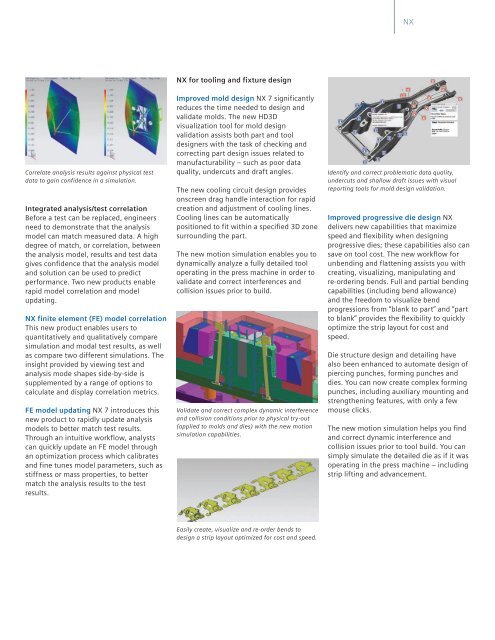
<strong>NX</strong>Correlate analysis results aga<strong>in</strong>st physical testdata to ga<strong>in</strong> confidence <strong>in</strong> a simulation.Integrated analysis/test correlationBefore a test can be replaced, eng<strong>in</strong>eersneed to demonstrate that the analysismodel can match measured data. A highdegree of match, or correlation, betweenthe analysis model, results and test datagives confidence that the analysis modeland solution can be used to predictperformance. Two <strong>new</strong> products enablerapid model correlation and modelupdat<strong>in</strong>g.<strong>NX</strong> f<strong>in</strong>ite element (FE) model correlationThis <strong>new</strong> product enables users toquantitatively and qualitatively comparesimulation and modal test results, as wellas compare two different simulations. The<strong>in</strong>sight provided by view<strong>in</strong>g test andanalysis mode shapes side-by-side issupplemented by a range of options tocalculate and display correlation metrics.FE model updat<strong>in</strong>g <strong>NX</strong> 7 <strong>in</strong>troduces this<strong>new</strong> product to rapidly update analysismodels to better match test results.Through an <strong>in</strong>tuitive workflow, analystscan quickly update an FE model throughan optimization process which calibratesand f<strong>in</strong>e tunes model parameters, such asstiffness or mass properties, to bettermatch the analysis results to the testresults.<strong>NX</strong> for tool<strong>in</strong>g and fixture designImproved mold design <strong>NX</strong> 7 significantlyreduces the time needed to design andvalidate molds. The <strong>new</strong> HD3Dvisualization tool for mold designvalidation assists both part and tooldesigners with the task of check<strong>in</strong>g andcorrect<strong>in</strong>g part design issues related tomanufacturability – such as poor dataquality, undercuts and draft angles.The <strong>new</strong> cool<strong>in</strong>g circuit design providesonscreen drag handle <strong>in</strong>teraction for rapidcreation and adjustment of cool<strong>in</strong>g l<strong>in</strong>es.Cool<strong>in</strong>g l<strong>in</strong>es can be automaticallypositioned to fit with<strong>in</strong> a specified 3D zonesurround<strong>in</strong>g the part.The <strong>new</strong> motion simulation enables you todynamically analyze a fully detailed tooloperat<strong>in</strong>g <strong>in</strong> the press mach<strong>in</strong>e <strong>in</strong> order tovalidate and correct <strong>in</strong>terferences andcollision issues prior to build.Validate and correct complex dynamic <strong>in</strong>terferenceand collision conditions prior to physical try-out(applied to molds and dies) with the <strong>new</strong> motionsimulation capabilities.Identify and correct problematic data quality,undercuts and shallow draft issues with visualreport<strong>in</strong>g tools for mold design validation.Improved progressive die design <strong>NX</strong>delivers <strong>new</strong> capabilities that maximizespeed and flexibility when design<strong>in</strong>gprogressive dies; these capabilities also cansave on tool cost. The <strong>new</strong> workflow forunbend<strong>in</strong>g and flatten<strong>in</strong>g assists you withcreat<strong>in</strong>g, visualiz<strong>in</strong>g, manipulat<strong>in</strong>g andre-order<strong>in</strong>g bends. Full and partial bend<strong>in</strong>gcapabilities (<strong>in</strong>clud<strong>in</strong>g bend allowance)and the freedom to visualize bendprogressions from “blank to part” and “partto blank” provides the flexibility to quicklyoptimize the strip layout for cost andspeed.Die structure design and detail<strong>in</strong>g havealso been enhanced to automate design ofpierc<strong>in</strong>g punches, form<strong>in</strong>g punches anddies. You can now create complex form<strong>in</strong>gpunches, <strong>in</strong>clud<strong>in</strong>g auxiliary mount<strong>in</strong>g andstrengthen<strong>in</strong>g features, with only a fewmouse clicks.The <strong>new</strong> motion simulation helps you f<strong>in</strong>dand correct dynamic <strong>in</strong>terference andcollision issues prior to tool build. You cansimply simulate the detailed die as if it wasoperat<strong>in</strong>g <strong>in</strong> the press mach<strong>in</strong>e – <strong>in</strong>clud<strong>in</strong>gstrip lift<strong>in</strong>g and advancement.Easily create, visualize and re-order bends todesign a strip layout optimized for cost and speed.