UniFi AP and UniFi AP L-R User Guide - Ubiquiti Networks
UniFi AP and UniFi AP L-R User Guide - Ubiquiti Networks
UniFi AP and UniFi AP L-R User Guide - Ubiquiti Networks

Create successful ePaper yourself
Turn your PDF publications into a flip-book with our unique Google optimized e-Paper software.
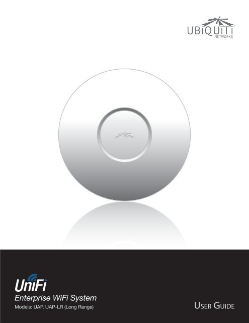
Enterprise WiFi SystemModels: U<strong>AP</strong>, U<strong>AP</strong>-LR (Long Range)
<strong>UniFi</strong> <strong>AP</strong>/<strong>AP</strong>-LR <strong>User</strong> <strong>Guide</strong>Table of ContentsTable of ContentsChapter 1: Product Overview .......................................1Package Contents ................................................................1System Requirements ............................................................1Network Topology Requirements .................................................1Front .............................................................................2Back .............................................................................2Chapter 2: Installation ..............................................3Hardware Installation .............................................................3Software Installation ..............................................................5Chapter 3: Using the <strong>UniFi</strong> Controller Software ......................7Interface Tabs ....................................................................7Common Interface Options .......................................................7Recent Events ....................................................................7Settings ..........................................................................8Admin ..........................................................................13Chapter 4: Map Tab ................................................14Adding Custom Maps. . . . . . . . . . . . . . . . . . . . . . . . . . . . . . . . . . . . . . . . . . . . . . . . . . . . . . . . . . . .14Adding a Google Map .............................................. 15Placing Access Points on the Map ................................................17Setting the Map Scale ...........................................................19Chapter 5: Statistics Tab ...........................................21Clients ..........................................................................21Quick Look ......................................................................21Current Usage - Top Access Points ...............................................22Recent Activities .................................................................22Chapter 6: Access Points Tab .......................................23Chapter 7: <strong>User</strong>s Tab ...............................................25Chapter 8: Guests Tab .............................................27Chapter 9: Offline Clients Tab ......................................29Chapter 10: Access Point Details ...................................30Details .........................................................................30<strong>User</strong>s ...........................................................................32Guests .........................................................................32Configuration ..................................................................33<strong>Ubiquiti</strong> <strong>Networks</strong>, Inc.i
<strong>UniFi</strong> <strong>AP</strong>/<strong>AP</strong>-LR <strong>User</strong> <strong>Guide</strong>Table of ContentsChapter 11: <strong>User</strong>/Guest Details ....................................39Details ..........................................................................39Statistics ........................................................................39Configuration ...................................................................40Chapter 12: HotSpot Manager .....................................41Appendix A: Portal Customization .................................43Overview ........................................................................43Enabling Portal Customization ...................................................43Viewing the Default Portal .......................................................43Setup ...........................................................................43Appendix B: <strong>UniFi</strong> Discovery Utility ................................45Overview ........................................................................45Appendix C: Specifications ........................................47Appendix D: Safety Notices ........................................49Electrical Safety Information .....................................................49Appendix E: Warranty .............................................50General Warranty ................................................................50Appendix F: Compliance Information ..............................51Installer Compliance Responsibility ..............................................51FCC .............................................................................51Industry Canada .................................................................51RF Exposure Warning ............................................................51CE Marking ......................................................................51RoHS/WEEE Compliance Statement ..............................................52Appendix G: Declaration of Conformity ............................53Appendix H: Contact Information ..................................54<strong>Ubiquiti</strong> <strong>Networks</strong> Support ......................................................54<strong>Ubiquiti</strong> <strong>Networks</strong>, Inc.ii
<strong>UniFi</strong> <strong>AP</strong>/<strong>AP</strong>-LR <strong>User</strong> <strong>Guide</strong>Chapter 1: Product OverviewThank you for purchasing the <strong>Ubiquiti</strong> <strong>UniFi</strong> EnterpriseWiFi System. The <strong>UniFi</strong> Enterprise WiFi System includesthe <strong>UniFi</strong> Controller software that allows you to manageyour wireless network using your Web browser.This <strong>User</strong> <strong>Guide</strong> is for use with version 2.0 or above ofthe <strong>UniFi</strong> Controller software with the following <strong>UniFi</strong>Enterprise WiFi System Access Point models:Model<strong>UniFi</strong> <strong>AP</strong>(U<strong>AP</strong>)<strong>UniFi</strong> <strong>AP</strong> Long Range(U<strong>AP</strong>-LR)Maximum PowerConsumption4W6WMaximum TXPower20 dBm27 dBmSystem RequirementsChapter 1: Product Overview• Microsoft Windows XP, Windows Vista, Windows 7, orMac OS X• Java Runtime Environment 1.6 (or above)• Web Browser: Mozilla Firefox, Google Chrome, orMicrosoft Internet Explorer 8 (or above)Network Topology Requirements• A DHCP-enabled network (for the <strong>AP</strong> to obtain anIP address as well as for the wireless clients afterdeployment)• A management station computer running the <strong>UniFi</strong>Controller software, located either onsite <strong>and</strong> connectedto the same Layer-2 network, or off-site in a cloud orNOCUnless otherwise needed to specify differences betweenthe two models, this <strong>User</strong> <strong>Guide</strong> will refer to both as <strong>UniFi</strong><strong>AP</strong>. Additional information is available on our website athttp://wiki.ubnt.com/<strong>UniFi</strong>_FAQWirelessUplinked 1U<strong>AP</strong>/U<strong>AP</strong>-LRThe <strong>UniFi</strong> Enterprise WiFi System also includes thenecessary hardware for mounting the unit on a wall or aceiling. The <strong>UniFi</strong> Enterprise WiFi System supports PassivePoE which works with the included PoE adapter. If youwant to power the <strong>UniFi</strong> <strong>AP</strong> from an 802.3af compliantswitch, <strong>Ubiquiti</strong> <strong>Networks</strong> offers the optional Instant802.3af Adapter to instantly transform any PoE device intoa fully 48V 802.3af compliant product. Product details areavailable on our website at http://ubnt.com/8023afWired U<strong>AP</strong>/U<strong>AP</strong>-LRRouterU<strong>AP</strong>/U<strong>AP</strong>-LRPackage ContentsorWa l MountOn-SiteManagement StationOff-SiteCloud/NOC 2Sample Network Topology<strong>UniFi</strong> <strong>AP</strong> Wall-Mount Bracket Ceiling-Mount Plate1 Please refer to “Wireless Uplinks” on page 35 forsetting up wireless-linked <strong>AP</strong>s.2 All <strong>UniFi</strong> <strong>AP</strong>s support off-site management controllers.<strong>UniFi</strong> ControllerCD with <strong>User</strong> <strong>Guide</strong>Quick Start <strong>Guide</strong>24v PoEAdapterPower CordM3x50 Flat HeadScrews(Qty. 3)M3 Keps Nut withTooth Washer(Qty. 3)M2.9x20 Self TappingScrew (Qty. 3)M3x20 ScrewAnchor (Qty. 3)<strong>Ubiquiti</strong> <strong>Networks</strong>, Inc.1
<strong>UniFi</strong> <strong>AP</strong>/<strong>AP</strong>-LR <strong>User</strong> <strong>Guide</strong>FrontBackChapter 1: Product OverviewReset Button The reset button serves two functions:• Restart It will restart the device when you press<strong>and</strong> release it quickly.• Restore Factory Defaults When you press <strong>and</strong>hold it for more then five seconds, it will restore thedevice to the factory default settings.LED Indicates the status of the device. Seethe table below for details.Ethernet Port Connects to the 24V PoEAdapter to provide power to the unit.LED ColorFlashing AmberSteady AmberAlternatingAmber/GreenQuickly FlashingGreenStatusInitializing.Factory default, waiting to be integrated.Device is busy; do not touch or unplug it.This usually indicates a process such as afirmware upgrade is taking place.This is used to locate an <strong>AP</strong>.When you click Locate in the <strong>UniFi</strong>Controller software, the <strong>AP</strong> will flash. It willalso display the location of the <strong>AP</strong> on themap.Steady GreenIndicates the device has been successfullyintegrated into a network <strong>and</strong> is workingproperly.Steady Greenwith occasionalflashingIndicates the device is in an isolated state(all WLANs are brought down until anuplink is found).<strong>Ubiquiti</strong> <strong>Networks</strong>, Inc.2
<strong>UniFi</strong> <strong>AP</strong>/<strong>AP</strong>-LR <strong>User</strong> <strong>Guide</strong>Chapter 2: InstallationHardware InstallationThe <strong>UniFi</strong> Enterprise WiFi System is powered by theincluded PoE (Power over Ethernet) adapter. To install the<strong>AP</strong>, perform the following steps:1. Connect an Ethernet cable to the Ethernet port on the<strong>UniFi</strong> Enterprise WiFi System.Chapter 2: InstallationBelow is an overview of the Power over Ethernetconnections.Power Connection Diagram2. Connect the power cord to the power port on the PoEAdapter. Connect the other end to of the power cord toa power outlet.Mounting the Access PointThe <strong>UniFi</strong> Enterprise WiFi System can be wall-mountedor mounted on a ceiling. Perform the steps for theappropriate installation:Wall-Mount1. Align the Wall-Mount Bracket with the Wall Mount textfacing up. There are horizontal <strong>and</strong> vertical lines on thebracket to help with orientation.Wall MountWall Mount text3. Connect the other end of the Ethernet cable to theEthernet port labeled PoE on the PoE Adapter.Note: If you plan to mount the <strong>AP</strong> on your ceiling,perform the ceiling mount installation stepsbefore connecting the Ethernet cable to the PoEAdapter.2. Use a pencil to mark the holes on the wall.3. Use a 6 mm drill bit to drill the holes in the wall.4. Insert the 3 M3x20 Screw Anchors into the wall.5. Secure the Wall-Mount Bracket to the wall by insertingthe M2.9x20 Self Tapping Screws into the anchors.Wa l Mount<strong>Ubiquiti</strong> <strong>Networks</strong>, Inc.3
<strong>UniFi</strong> <strong>AP</strong>/<strong>AP</strong>-LR <strong>User</strong> <strong>Guide</strong>Chapter 2: InstallationSoftware InstallationInsert the <strong>UniFi</strong> Controller software CD into your CD‐ROMdrive <strong>and</strong> follow the instructions for your specificcomputer type.Mac <strong>User</strong>s1. Click the Install icon.PC <strong>User</strong>s1. Launch <strong>UniFi</strong>-installer.exe.2. Click Install.3. If your computer doesn’t have Java 1.6 or aboveinstalled, you will be prompted to install it. Click Installto continue.2. Click Continue <strong>and</strong> follow the on-screen instructions toinstall the software.4. Click Next.3. Go to Go > Applications <strong>and</strong> double-click the <strong>UniFi</strong>icon.5. Ensure that the Start <strong>UniFi</strong> Controller after installationoption is checked <strong>and</strong> click Finish.Proceed to “Configuring the <strong>UniFi</strong> Controller Software”on page 6.Note: The <strong>UniFi</strong> Controller software can also belaunched from Start > All Programs.<strong>Ubiquiti</strong> <strong>Networks</strong>, Inc.5
<strong>UniFi</strong> <strong>AP</strong>/<strong>AP</strong>-LR <strong>User</strong> <strong>Guide</strong>Configuring the <strong>UniFi</strong> Controller Software1. The <strong>UniFi</strong> Controller software startup will begin. Whenthe option becomes available, click Launch a Browserto Manage Wireless Network.Chapter 2: Installationc. To enable guest access, select Enable Guest Access<strong>and</strong> enter a guest network name in the Guest SSIDfield.d. Click Next.5. Enter an admin name in the Admin Name field <strong>and</strong>password in the Password field to use when accessingthe management interface. Confirm your password inthe Confirm field. Click Next.2. Select your language <strong>and</strong> country. Alternatively, youclick restore from a previous backup to use a file thatcontains your backup settings. Click Next.6. On the Finish tab, review your settings. Click Back tomake changes or Finish to save your settings. Oncefinished you will be redirected to the managementinterface via your web browser.3. Select the devices that you want to configure <strong>and</strong> clickNext.4. The <strong>UniFi</strong> Installation Wizard will create a secureprimary wireless network for your devices. Perform thefollowing steps:Congratulations, your wireless network is now configured.A login screen will appear for the <strong>UniFi</strong> Controllermanagement interface. Enter the admin name <strong>and</strong>password that you created <strong>and</strong> click Login.a. Enter a unique wireless network name (SSID) in theSecure SSID field.b. Enter a unique passphrase to be used for yourprimary network in the Security Key field.Proceed to the next chapter for information on using the<strong>UniFi</strong> Controller software.<strong>Ubiquiti</strong> <strong>Networks</strong>, Inc.6
<strong>UniFi</strong> <strong>AP</strong>/<strong>AP</strong>-LR <strong>User</strong> <strong>Guide</strong>Chapter 3: Using the <strong>UniFi</strong>Controller SoftwareThe <strong>UniFi</strong> Controller software that comes with your <strong>UniFi</strong>Enterprise WiFi System has a browser-based interface foreasy configuration <strong>and</strong> management.To access the interface, perform the following steps:1. Launch the <strong>UniFi</strong> Controller application if hasn’t alreadybeen started.• Mac users: Go > Applications > <strong>UniFi</strong>• Windows users: Start > All Programs > <strong>Ubiquiti</strong><strong>UniFi</strong>.2. The <strong>UniFi</strong> login screen will appear. Enter the adminname <strong>and</strong> password in the appropriate fields <strong>and</strong> clickLogin.Access PointsChapter 3: Using the <strong>UniFi</strong> Controller Software• connected Drop-down clickable list of all of the AccessPoints that are online.• disconnected Displays a list of Access Points that werepreviously online but are no longer accessible.• pending Drop-down clickable list of all of the AccessPoints that are not yet managed but are available formanagement.Stations• users Displays the total number of users connected tothe primary network.• guests Displays the total number of users connected tothe guest network.Recent EventsDisplays a list of recent events including the date <strong>and</strong> timethe event occurred <strong>and</strong> the details of the event. The <strong>User</strong><strong>and</strong> Access Point names are clickable links.Interface TabsThe <strong>UniFi</strong> software consists of six primary tabs. This <strong>User</strong><strong>Guide</strong> covers each tab with a chapter. For details, on aspecific tab, refer to the appropriate chapter.• “Map Tab” on page 14• “Statistics Tab” on page 21• “Access Points Tab” on page 23• “<strong>User</strong>s Tab” on page 25• “Guests Tab” on page 27• “Offline Clients Tab” on page 29Common Interface OptionsThe common interface options are accessible from all tabsin the <strong>UniFi</strong> interface.Event Slider Move the slider right <strong>and</strong> left to navigatebetween pages of events.Search Allows you to enter text you want to search for.Simply begin typing, there is no need to press Enter.Clicking on an Event Device LinkThe event messages have clickable links [in bracketsunderlined in gray text] for <strong>AP</strong> (See “Access Point Details”on page 30), <strong>User</strong> <strong>and</strong> Guest (See “<strong>User</strong>/Guest Details”on page 39). Details vary based on the selection.<strong>Ubiquiti</strong> <strong>Networks</strong>, Inc.7
<strong>UniFi</strong> <strong>AP</strong>/<strong>AP</strong>-LR <strong>User</strong> <strong>Guide</strong>AlertsImportant events are displayed in the alerts window. Thedate <strong>and</strong> time of the event <strong>and</strong> the message are displayed.Settings > SystemChapter 3: Using the <strong>UniFi</strong> Controller SoftwareSearch Allows you to enter text you want to search for.Simply begin typing, there is no need to press Enter.Show Archived Show all of the alert messages that havebeen archived.Archive All Archive all of the alert messages displayed onthe screen.Adopt Click to adopt an Access Point that is waiting foradoption.Archive Archive the selected alert message.Settings>_System System related settings.Guest Control Guest portal <strong>and</strong> policies.Wireless <strong>Networks</strong> Wireless networks.Blocked Devices List of blocked wirelessdevices.Admin Settings Admin username, password<strong>and</strong> preferences.System ConfigurationSystem Name Editable field with the system name.Country Select your country from the drop-down list.ServicesAutomatic Upgrade When enabled, this option willautomatically upgrade your firmware when an update isavailable.LED When enabled, the LED on the Access Point will lightup. When disabled, the LED will turn off.Background Scanning When this option is enabled, allmanaged Access Points will scan in the background for“Rogue Access Points” – third-party or <strong>UniFi</strong> Access Pointsthat are being managed by another instance of the <strong>UniFi</strong>Controller software. This option is disabled by default.• Scan Now When clicked, all managed Access Pointswill scan across all maps for two to three seconds. NewAccess Points in their default state will appear underAccess Points > Pending.Load Balancing Sets a desired number of clients per <strong>AP</strong>.While an <strong>AP</strong> will allow more clients to connect, it will startto look at those with lower signals <strong>and</strong> disconnect them.Network Discovery When enabled, this option allows<strong>UniFi</strong> to be discoverable via UPnP. This option is disabledby default.Uplink Connectivity Monitor It monitors the uplinks ofthe managed Access Points, either wired or wireless, bychecking to see if the gateway/custom IP can be reached.The monitor <strong>and</strong> wireless uplink capability are enabled bydefault.• Use default gateway Use default gateway is selected bydefault; all managed Access Points will use the gatewayof the Access Point that is providing IP information,either by DHCP or Static designation.• Use custom IP Select Use custom IP to specify anIP address; all managed Access Points will use the IPaddress you enter in the Uplink IP address field.<strong>User</strong> Groups <strong>User</strong> Group settings.<strong>Ubiquiti</strong> <strong>Networks</strong>, Inc.8
<strong>UniFi</strong> <strong>AP</strong>/<strong>AP</strong>-LR <strong>User</strong> <strong>Guide</strong>Remote Logging Enable to define a remote syslog server.Enter the IP address <strong>and</strong> port of the syslog server.Click Apply to save any changes that you have made.Mail ServerWhen enabled, <strong>UniFi</strong> will send email alerts when triggered(Pending Access Points <strong>and</strong> Discconnected Access Points)to the administrator email address specified underSettings > Admin Settings > Admin Preferences > Email Alert.Chapter 3: Using the <strong>UniFi</strong> Controller Software• No authentication When this option is selected, guestsare not required to log in, but must accept the Termsof Use. When you select No authentication, you mustselect Guest Policy under Settings > Wireless <strong>Networks</strong> >SSID > Edit > Wireless Configurations in order to enforceselection of the Terms of Use by the guest.SMTP Server Enable by selecting the check box<strong>and</strong> entering the outgoing (SMTP) mail server name.Optionally, you may enable Secure Sockets Layer (SSL) toprovide communication security over the Internet. Theport number will automatically change to 465.Enable authentication Enable by selecting the check box<strong>and</strong> entering the username <strong>and</strong> password required by themail server.Test SMTP Server Enter an email address <strong>and</strong> click Sendto test the mail server setup.Apply Click Apply to save changes.Settings > Guest Control• Simple Password When this option is selected, guestsare required to enter the simple password <strong>and</strong> acceptthe Terms of Use. When you select Simple Password,you must select Guest Policy under Settings > Wireless<strong>Networks</strong> > SSID > Edit > Wireless Configurations in orderto enforce entry of the password <strong>and</strong> selection of theTerms of Use by the guest.• Hotspot When selected, enables Hotspot functionalityincluding the ability to customize portal login pages <strong>and</strong>bill customers using major credit cards or via PayPal .When you select Hotspot, you must select:• Voucher or Payment in the Hotspot section as amethod of Hotspot authorization• Guest Policy to enforce entry of voucher, payment,<strong>and</strong> Terms of Use by the guest (Go to Settings >Wireless <strong>Networks</strong> > Name_of_wireless_network > Edit >Wireless Configurations.)Guest PoliciesGuest Portal This option is disabled by default. Whendisabled, guests can access the Internet without enteringa password or accepting Terms of Use. When this option isenabled, you can control the Guest Portal.Authentication When the Guest Portal is enabled, theauthentication options will appear. There are four differentauthentication methods available:• External Portal Server If using an external server tohost a custom guest portal, enter the IP address in theCustom Portal > IP Address box using the followingformat: 192.168.0.0.• Guest Password (Option only available when usingSimple Password authentication) Enter a password thatguests must enter before accepting the Terms of Use<strong>and</strong> connecting to the Internet.<strong>Ubiquiti</strong> <strong>Networks</strong>, Inc.9
<strong>UniFi</strong> <strong>AP</strong>/<strong>AP</strong>-LR <strong>User</strong> <strong>Guide</strong>• Expiration (Option only available when using Noauthentication or Simple Password authentication)Allows the specification of guest login expiration aftera designated period of time. Options include: 8 hours,24 hours, 2 days, 3 days, 4 days, 7 days, <strong>and</strong> <strong>User</strong>-defined.<strong>User</strong>-defined can be designated in minutes, hours, <strong>and</strong>days.• Custom Portal (Option only available when usingExternal Portal Server authentication) Enter the IPaddress using the following format: 192.168.0.0.• L<strong>and</strong>ing Page (Option only available when usingNo authentication, Simple Password, or Hotspotauthentication) The l<strong>and</strong>ing page is the page whereguests are redirected after accepting the Terms of Use.There are two options available:--Redirect to the original URL When this optionis selected, guests are directed to the URL theyrequested after accepting the Terms of Use.--Promotional URL When this option is selected,guests are redirected to the URL that you specify hereafter accepting the Terms of Use. Specify the URL withhttp:// in front of the Web address.Example: http://www.ubnt.com• Portal Customization (Option only available whenusing No authentication, Simple Password, or Hotspotauthentication) When enabled, allows customized portalpages to appear in place of default login pages. See“Portal Customization” on page 43 for details onsetting up custom portal pages.• Portal URL Hostname Allows the designation of ahostname for the portal URL in place of the defaultIP address. Paired with a SSL certificate, ensures sitecertificates are displayed as trusted in the guest browser.Example: www.ubnt.comHotspotThe Hotspot options are only available when Hotspotauthentication is selected.• Voucher When selected, vouchers (includingdistributable code, duration values, <strong>and</strong> use restrictions)can be created using Hotspot Manager (see “HotSpotManager” on page 41).• Payment When enabled, allows payment-basedauthentication to be set up with your PayPal WebsitePayments Pro account. Payment <strong>and</strong> Transctions canbe managed using Hotspot Manager (see “HotSpotManager” on page 41).• PayPal PayPal account details are entered here:--<strong>User</strong>name Enter the corresponding <strong>User</strong>name.--Password Enter the corresponding Password.--Signature Enter the corresponding Signature for thePayPal account to be used for receiving payments.Chapter 3: Using the <strong>UniFi</strong> Controller Software--Use Paypal S<strong>and</strong>box For PayPal testing purposes,enable this option <strong>and</strong> click Apply S<strong>and</strong>boxAccount to set up/access your PayPal S<strong>and</strong>box TestEnvironment.• Hotspot Operator Click Go to Hotspot Managerto manage Wireless Guests, Payments/Transactions,Vouchers, <strong>and</strong> Operator Accounts. See “HotSpotManager” on page 41.• Apply Click Apply to save changes.When logging in with No authentication, guests will berequired to accept the Terms of Use before gaining accessto the Internet.When logging in with Simple Password authentication,guests will be required to enter the Guest Password <strong>and</strong>accept the Terms of Use before gaining access to theInternet.When logging in with Voucher-based Hotspotauthentication, guests will be required to enter thevoucher number <strong>and</strong> accept the Terms of Use beforegaining access to the Internet.<strong>Ubiquiti</strong> <strong>Networks</strong>, Inc.10
<strong>UniFi</strong> <strong>AP</strong>/<strong>AP</strong>-LR <strong>User</strong> <strong>Guide</strong>When logging in with Payment-based Hotspotauthentication, guests will be required to select packagetype, payment choice <strong>and</strong> accept the Terms of Use beforegaining access to the Internet.Access ControlRestricted Subnets Enter in any subnets that you don’twant guests to be able to access.Apply Click Apply to save changes.Settings > Admin SettingsChapter 3: Using the <strong>UniFi</strong> Controller SoftwareWireless ConfigurationsName Displays the wireless network name (SSID).Security Displays the type of security being used on yourwireless network.Guest Network Indicates whether the network is a guestnetwork.Actions Select an action button to perform the desiredaction:Edit Select to make changes to the wireless networksettings.Delete Select to delete the wireless network.Wireless ConfigurationAdmin Name Displays the current admin name usedto login. To change the admin name, simply enter a newname <strong>and</strong> click Apply.Password A new password can be entered in this field. Besure to enter the password again in the Confirm field <strong>and</strong>then click Apply to save your new password.Confirm Used to confirm your new password.Language Selects the language for use in the interface.Email Alert Select to enable email alerts <strong>and</strong> enter theadministrator email address in the Send alert to emailbox. See “Mail Server” on page 9 for information onsetting up the outgoing (SMTP) mail server.Apply Click Apply to save changes.Settings > Wireless <strong>Networks</strong>• Name/SSID Allows you to edit the wireless networkname (SSID).• Security Selects the type of security to use on yourwireless network.--Open This option is typically only used on the Guestnetwork. When enabled, wireless network access isopen to anyone without needing a password.--WEP WEP (Wired Equivalent Privacy) is the oldest <strong>and</strong>least secure security algorithm. WPA security methodsshould be used when possible.• WEP Key Enter a WEP encryption key inhexadecimal format. You can enter a 64-bit or 128-bit key:Type64-bit128-bitHex10 Hexadecimal Characters(0-9, A-F, or a-f )Example: 00112233AANote: You can use 5 printable characters,which will be translated to thecorresponding HEX code.26 Hexadecimal Characters(0-9, A-F, or a-f )Example:00112233445566778899AABBCCNote: You can use 13 printablecharacters, which will be translated to thecorresponding HEX code.• Key Index Specifies the Index of the WEP Key used.4 different WEP keys can be configured at the sametime, but only one is used. The effective key is set bychoosing 1, 2, 3 or 4.<strong>Ubiquiti</strong> <strong>Networks</strong>, Inc.11
<strong>UniFi</strong> <strong>AP</strong>/<strong>AP</strong>-LR <strong>User</strong> <strong>Guide</strong>--WPA-Personal WPA or Wi-Fi Protected Access wasdeveloped as a stronger encryption method over WEP.WPA-Personal requires a passphrase to connect to thewireless network.• Security Key Enter the passphrase that users willuse to connect to the wireless network.--WPA-Enterprise WPA Enterprise uses a RADIUSserver to authenticate users on the wireless network.• IP Address This is where the IP address of theRADIUS server is specified.• Port The port number is entered here. By default itis 1812.• Password The password used to authenticate onthe RADIUS server is entered here.• Guest Policy Select this option to enable guest accesspolicies on this wireless network.Advanced• VLAN To use a VLAN, select Use VLAN ID <strong>and</strong> enter theport number.• Hide SSID Select this option if you don’t want the SSIDto be broadcast.• WPA Defines supported WPA <strong>and</strong> encryption methods.• <strong>User</strong> Group Allows assignment of wireless users to aspecific user group.Click Apply to save any changes that you have made.Click Cancel to discard changes.Settings > Blocked DevicesDisplays the list of blocked wireless devices.Chapter 3: Using the <strong>UniFi</strong> Controller SoftwareSettings > <strong>User</strong> GroupsCreate Click to create a new user group.• Name Enter a descriptive user group name.• B<strong>and</strong>width Limit (Download) When selected, allowsthe designation of a download b<strong>and</strong>width limit in Kbps.• B<strong>and</strong>width Limit (Upload) When selected, allows thedesignation of a upload b<strong>and</strong>width limit in Kbps.--Create Click to create user group.--Cancel Click to cancel user group creation.Unblock Click to unblock a wireless device. See “<strong>User</strong>/Guest Details” on page 39 for information on blockingwireless devices.Edit Click to change the name or b<strong>and</strong>width settings ofthe user group.Delete Click to delete the user group.See “Configuration” on page 40 for information on theapplication of <strong>User</strong> Groups to <strong>User</strong>s/Guests.<strong>Ubiquiti</strong> <strong>Networks</strong>, Inc.12
<strong>UniFi</strong> <strong>AP</strong>/<strong>AP</strong>-LR <strong>User</strong> <strong>Guide</strong>Chapter 3: Using the <strong>UniFi</strong> Controller SoftwareAdminThe Admin tab displays server version information,allows system backups to be created <strong>and</strong> downloaded,allows system restoration from backup files <strong>and</strong> allowsconfiguration information to be downloaded to assist insupport issues.Server InformationVersion The software version is displayed here. If thereis an update, <strong>UniFi</strong> will automatically download it <strong>and</strong>display it here.BackupDownload Backup Settings Click to download a file thatcontains all of your settings so you can restore them laterif you choose.RestoreChoose File Select this option to restore settings from abackup file that you’ve already downloaded.Support InfoDownload Support Info Select this option to downloada file to your computer with information about yourconfiguration that can be emailed to our support team.<strong>Ubiquiti</strong> <strong>Networks</strong>, Inc.13
<strong>UniFi</strong> <strong>AP</strong>/<strong>AP</strong>-LR <strong>User</strong> <strong>Guide</strong>Chapter 4: Map TabChapter 4: Map TabThe <strong>UniFi</strong> Controller software allows you to upload custommap images of your location(s) or use Google Maps for avisual representation of your wireless network. When youinitially launch the <strong>UniFi</strong> Controller application, a defaultmap is displayed.Adding Custom MapsOnce you’ve created the map, you can upload it to the<strong>UniFi</strong> Controller software by performing the followingsteps:1. Click Configure Maps.Configure Maps button2. Click Add a Map.Add a MapTo add a custom map, you must first create the imageusing an illustration, image editing, or blueprintapplication that exports .jpg, .gif, or .png file formats.<strong>Ubiquiti</strong> <strong>Networks</strong>, Inc.14
<strong>UniFi</strong> <strong>AP</strong>/<strong>AP</strong>-LR <strong>User</strong> <strong>Guide</strong>Chapter 4: Map Tab3. Enter a map name in the Description field <strong>and</strong> clickUpload my own. Click the Browse button to locate thefile to use as a map (valid file formats are .jpg, .gif, <strong>and</strong>.png). Click Continue.2. Click Add a Map.Add a Map4. Click Close.3. Enter a map name in the Description field <strong>and</strong> click UseGoogle Maps. Click Continue.Adding a Google MapTo add a Google Map into the <strong>UniFi</strong> Controller softwareMap view:1. Click Configure Maps.4. In order to use a Google Map, you must registerwith Google for a Google Maps <strong>AP</strong>I key. To do so, clickSpecify <strong>AP</strong>I Key.Configure Maps button<strong>Ubiquiti</strong> <strong>Networks</strong>, Inc.15
<strong>UniFi</strong> <strong>AP</strong>/<strong>AP</strong>-LR <strong>User</strong> <strong>Guide</strong>5. Click or copy <strong>and</strong> paste the web link from the windowinto a new web browser window. Do not close the<strong>UniFi</strong> window.http://code.google.com/apis/maps/signup.htmlChapter 4: Map Tab11. A new window will open displaying your key. Highlight<strong>and</strong> copy the Google Maps <strong>AP</strong>I key.Google Maps <strong>AP</strong>I Key6. You need to be signed in with a Google account toobtain a Google Maps <strong>AP</strong>I key.7. Review the terms <strong>and</strong> conditions <strong>and</strong> click thecheckbox next to I have read <strong>and</strong> agree with theterms <strong>and</strong> conditions.8. Navigate back to the <strong>UniFi</strong> window <strong>and</strong> copy theaddress that <strong>UniFi</strong> displays in the address bar.Note: You only need to copy until the end of theaddress; do not include the port information.In the example below, the full address ishttps://192.168.25.191:8443/manage#. You onlyneed to copy up to https://192.168.25.191. Do notinclude the colon or anything beyond it.9. Navigate back to the Google Maps <strong>AP</strong>I Family window<strong>and</strong> paste the address into the My web site URL: box.10. Click the Generate <strong>AP</strong>I Key button.12. Navigate back to the <strong>UniFi</strong> window <strong>and</strong> paste the <strong>AP</strong>IKey into the <strong>AP</strong>I Key field. Click continue.13. The default Google Map location will appear. Click theSet Location button in the lower left.Set Location button<strong>Ubiquiti</strong> <strong>Networks</strong>, Inc.16
<strong>UniFi</strong> <strong>AP</strong>/<strong>AP</strong>-LR <strong>User</strong> <strong>Guide</strong>14. Select Specify Address to enter an address. Type in theaddress <strong>and</strong> then click Go. You also have the SpecifyCoordinates option to enter the latitude <strong>and</strong> longitudeof a specific location.Chapter 4: Map TabPlacing Access Points on the Map1. Drag the Access Point icon(s) from the Unplaced <strong>AP</strong>slist on the left to the appropriate location(s) on the map.15. The specified location should appear. Click Save.The access point will appear in the area that you placed it.16. Click Close.17. You can adjust the zoom using the slider on the right.<strong>Ubiquiti</strong> <strong>Networks</strong>, Inc.17
<strong>UniFi</strong> <strong>AP</strong>/<strong>AP</strong>-LR <strong>User</strong> <strong>Guide</strong>Wired/Wireless Access Point Shows thelocation of the Access Point on the map.Click <strong>and</strong> hold this icon to drag the Access Pointto another location on the map. Click on theAccess Point icon to reveal additional options.Click a blank area of the map to hide them.Lock Locks the selected Access Point in thecurrent location on the map.Details Brings up the Details window. Thisallows you to view Access Point settings <strong>and</strong>connected users. You can also edit the radiochannel, transmit power, uplink <strong>and</strong> device alias.Chapter 4: Map Tab• Configuration Allows you to change the aliasname of the device, the channel setting, <strong>and</strong>set the transmit power to Auto, High, Medium,Low or Custom. You can also remove theAccess Point if you no longer want to manageit with the <strong>UniFi</strong> Controller software.Remove Remove the Access Point from thelocation on the map.Show: You can click each of the following options todisplay Access Point labels, details, wireless coverage <strong>and</strong>topology on the map.• Labels Displays the name applied to the Access Point.Refer to Alias under “Configuration” on page 28 tochange a name applied to an Access Point. If no customlabel is applied, the Access Point’s MAC address will bedisplayed.There are 4 tabs to select from in the Detailswindow. Details, <strong>User</strong>s, Guests, <strong>and</strong> Configuration.• Details Displays details on the Access Pointincluding the MAC address, model, version,IP address, uptime, connected users, <strong>and</strong>connected guests. Click Uplink (Wire) todisplay the speed, duplex, Down Pkts / Bytes,Up Pkts / Bytes <strong>and</strong> Activity. Click Radio todisplay the channel used, transmit power, <strong>and</strong>packet information.• <strong>User</strong>s Displays the hostname of the users thatare connected to the selected Access Point<strong>and</strong> the IP address assigned to them.You can click on the hostname to displayadditional details of each user. A windowwith Details, Statistics, <strong>and</strong> Configuration isdisplayed. The Details tab displays the MACaddress, hostname, IP address, uptime <strong>and</strong>the Access Point they are connected to. TheStatistics tab displays the channel used, signalstrength, transmit <strong>and</strong> receive rates, powersaving enabled or disabled, <strong>and</strong> the numberof packets sent <strong>and</strong> received. You can alsoclick History to see a sortable list of events.The Configuration tab allows you to changethe alias name for the device.• Guests Displays the MAC address of gueststhat are connected to the guest network.• Details Displays the Access Point name, MAC address,transmit/receive channel, number of users connected,<strong>and</strong> number of guests connected.<strong>Ubiquiti</strong> <strong>Networks</strong>, Inc.18
<strong>UniFi</strong> <strong>AP</strong>/<strong>AP</strong>-LR <strong>User</strong> <strong>Guide</strong>• Coverage Displays a visual representation of thewireless range covered by the Access Point.Chapter 4: Map TabZoom Slider Use to zoom the map detail in <strong>and</strong> out.Topology Displays a visual representation of the networkconfiguration <strong>and</strong> connections between Access Points.Devices that are wirelessly connected will have a wirelessicon next to them. A path of arrows will indicate whichdevice the wireless device is downlinking from.Set Map Scale Use this option to define the scale of themap. You will draw a line <strong>and</strong> define the distance that theline represents.Setting the Map Scale1. Click the Set Map Scale button.2. Click <strong>and</strong> hold to draw a line in the area that you wantto use to set the scale of the map. If you need to redrawthe line, just click <strong>and</strong> hold again to draw a new line.Once you’re happy with the line, click Next.Map: If multiple maps have been uploaded, you canselect which map you want to view using this option.Configure Maps Use this option to add maps or edit thecurrent map(s).<strong>Ubiquiti</strong> <strong>Networks</strong>, Inc.19
<strong>UniFi</strong> <strong>AP</strong>/<strong>AP</strong>-LR <strong>User</strong> <strong>Guide</strong>Chapter 4: Map Tab3. Enter the distance that the line represents in theDistance: field. The distance is specified in meters bydefault but you can switch to feet using the drop-downselection menu on the right. Click Next.<strong>Ubiquiti</strong> <strong>Networks</strong>, Inc.20
<strong>UniFi</strong> <strong>AP</strong>/<strong>AP</strong>-LR <strong>User</strong> <strong>Guide</strong>Chapter 5: Statistics TabChapter 5: Statistics TabQuick LookThe Statistics tab provides a visual representation of thenetwork traffic connected to your managed <strong>AP</strong>s. Chartsrepresenting the number of clients <strong>and</strong> network traffic aredisplayed. An hour by hour chart of the usage over the last24 hours is also displayed on this screen.Clients# of Clients Displays a a visual pie chart representationof the client distribution. Place the mouse cursor over thechart for percentage details.Most Active <strong>AP</strong> Displays the most active Access Pointdetails including the name or MAC address of the AccessPoint, the total amount of data sent <strong>and</strong> the total amountof data received.The name or MAC address of the Access Point is a clickablelink that will open the device details page. See “AccessPoint Details” on page 30 for additional information.Most Active Client Displays the details of the most activecurrently connected client. The name or MAC address ofthe client device,the total amount of data sent <strong>and</strong> thetotal amount of data received is displayed here.The name or MAC address of the client device is a clickablelink that will open the device details page. See “<strong>User</strong>/Guest Details” on page 39 for additional information.All-Time Top Client Displays the details of the all-timemost active client. The name or MAC address of the clientdevice,the total amount of data sent <strong>and</strong> the total amountof data received is displayed here.The name or MAC address of the client device is a clickablelink that will open the device details page. See “<strong>User</strong>/Guest Details” on page 39 for additional information.<strong>Ubiquiti</strong> <strong>Networks</strong>, Inc.21
<strong>UniFi</strong> <strong>AP</strong>/<strong>AP</strong>-LR <strong>User</strong> <strong>Guide</strong>Chapter 5: Statistics TabCurrent Usage - Top Access Points# of Clients Displays a a visual pie chart representationof the client distribution on the most active Access Points.Place the mouse cursor over the chart for percentagedetails.Traffic Displays a visual pie chart representation of trafficon the most active Access Points. Place the mouse cursorover the chart for percentage details.Recent ActivitiesThe Recent Activities statistics can be toggled between aview for the last 24 hours <strong>and</strong> also for the last 30 days.# of Clients Displays a a visual graph of the number ofclients connected during the selected time period (last 24hours or last 30 days).Traffic Displays a a visual graph of the network trafficduring the selected time period (last 24 hours or last 30days).<strong>Ubiquiti</strong> <strong>Networks</strong>, Inc.22
<strong>UniFi</strong> <strong>AP</strong>/<strong>AP</strong>-LR <strong>User</strong> <strong>Guide</strong>Chapter 6: Access Points TabChapter 6: Access Points TabThe Access Points tab displays a list of managed AccessPoints, each displaying its icon, name, IP address, status,number of clients connected, download/upload statistics,<strong>and</strong> transmit/receive channel. You can click any of thesecolumn headers to change the list order.Search Allows you to enter text you want to search for.Simply begin typing, there is no need to press Enter.Page Size Allows you to determine how many results aredisplayed per page. Select 10, 20, 30, 40, 60, or 100.Page Size Allows you to determine how many results aredisplayed per page. Select 10, 20, 30, 40, 60, or 100.Icon Displays the icon of the Access Point (icon willvary depending on model).Name/MAC Address Displays the hostname, alias, orMAC address of the Access Point. You can click on thename to get additional details on the Access Point.IP Address Displays the IP address of the Access Point.Status Displays the connection status information.• Connected Displays that the Access Point connection isphysically wired.• Connected (wireless) Displays that the Access Pointconnection is wirelessly downlinked to a physicallywired Access Point.<strong>Ubiquiti</strong> <strong>Networks</strong>, Inc.• Disconnected Displays if the Access Point isunreachable by the <strong>UniFi</strong> Controller software.Disconnected Access Points will also appear underAccess Points > Disconnected at the top of the interface.• Isolated A managed Access Point that is unable tolocate its uplink.• Managed by Other Displays if the Access Point is notin the default state but it is not controlled by the <strong>UniFi</strong>Controller.• Pending Approval Displays if the Access Point is in thedefault state <strong>and</strong> is available for adoption.Num Clients Displays the number of clients connected tothe Access Point.Download Displays the total size of downloads via theAccess Point.Upload Displays the total size of uploads via the AccessPoint.Channel Displays the transmit/receive channel beingused by the Access Point. The radio b<strong>and</strong> is represented as(ng) for 2.4 GHz <strong>and</strong> (na) for 5 GHz.Actions Select an action button to perform the desiredaction:• Restart Restart the selected Access Point.• Locate Click to locate the Access Point on the map. Thebutton will flash green <strong>and</strong> black until the Locate buttonis clicked again. The LED on the Access Point will flashso that you can place it in the correct location on themap. The LED will flash until the Locate button is clickedagain.23
<strong>UniFi</strong> <strong>AP</strong>/<strong>AP</strong>-LR <strong>User</strong> <strong>Guide</strong>Chapter 6: Access Points Tab• Adopt Click to adopt an Access Point that appearsunder Access Points > Pending at the top of the interface.The Status will appear as Adopting until the Access Pointis connected.• Upgrade If a software upgrade is available for theAccess Point, click Upgrade to install the latest <strong>UniFi</strong>firmware on the device. The Status will appear asUpgrading until the process is complete <strong>and</strong> the AccessPoints reconnects to the <strong>UniFi</strong> Controller software.<strong>Ubiquiti</strong> <strong>Networks</strong>, Inc.24
<strong>UniFi</strong> <strong>AP</strong>/<strong>AP</strong>-LR <strong>User</strong> <strong>Guide</strong>Chapter 7: <strong>User</strong>s TabChapter 7: <strong>User</strong>s TabThe <strong>User</strong>s tab displays a list of users that are connected tothe primary wireless network of the Access Point.Access Point Displays the hostname or alias of the AccessPoint. You can click the name to get additional details onthe Access Point.Signal Displays the signal strength <strong>and</strong> type from theAccess Point to the client. If a lightning bolt symbol ispresent, the device is in power save mode. The device willreturn to active mode when Down or Up activity resumes.Icon Clients Modea5 GHz (either 802.11a or 802.11n/a) Activea5 GHz (either 802.11a or 802.11n/a) Power SaveSearch Allows you to enter text you want to search for.Simply begin typing; there is no need to press Enter.• 2G Select if you only want users of the 2.4 GHz wirelessnetwork displayed.• 5G Select if you only want users of the 5 GHz wirelessnetwork displayed.• All Select to show all users.Filter by <strong>AP</strong> Drop-down list of all available Access Points.Select one to filter the results <strong>and</strong> display only usersconnected to the selected Access Point.Page Size Allows you to determine how many results aredisplayed per page. Select 10, 20, 30, 40, 60, or 100.Name/MAC Address Displays the hostname, alias, orMAC address of the connected user. You can click thename to get additional details.IP Address Displays the IP address assigned to the user.WLAN Displays the name of the SSID (network name) ofthe wireless LAN (WLAN) that the user is connected to.nnggbb2.4 GHz (802.11n) Active2.4 GHz (802.11n) Power Save2.4 GHz (802.11g) Active2.4 GHz (802.11g) Power Save2.4 GHz (802.11b) Active2.4 GHz (802.11b) Power SaveDown Displays the total bytes of data received by theuser.Up Displays the total bytes of data sent by the user.<strong>Ubiquiti</strong> <strong>Networks</strong>, Inc.25
<strong>UniFi</strong> <strong>AP</strong>/<strong>AP</strong>-LR <strong>User</strong> <strong>Guide</strong>Chapter 7: <strong>User</strong>s TabActivity Displays the level of activity for each user.BarsActivity Level(Bytes per second)Idle5008000640005120002048000Uptime Displays the total time the user has beenconnected for this session.Actions Click an action button to perform theappropriate action.• Block Click this button to block a specific user fromaccessing the Access Point. This will add the client to theBlocked Device list.• Reconnect Click this button to reconnect a specific userto the Access Point.<strong>Ubiquiti</strong> <strong>Networks</strong>, Inc.26
<strong>UniFi</strong> <strong>AP</strong>/<strong>AP</strong>-LR <strong>User</strong> <strong>Guide</strong>Chapter 8: Guests TabChapter 8: Guests TabThe Guests tab displays a list of users that have connectedto the guest network of the Access Point.Access Point Displays the hostname or alias of the AccessPoint. You can click the name to get additional details onthe Access Point.Signal Displays the signal strength <strong>and</strong> type from theAccess Point to the client. If a lightning bolt symbol ispresent, the device is in power save mode. The device willreturn to active mode when Down or Up activity resumes.Icon Clients Modea5 GHz (either 802.11a or 802.11n/a) Activea5 GHz (either 802.11a or 802.11n/a) Power SaveSearch Allows you to enter text you want to search for.Simply begin typing; there is no need to press Enter.• 2G Select if you only want guests of the 2.4 GHzwireless network displayed.• 5G Select if you only want guests of the 5 GHz wirelessnetwork displayed.• All Select to show all guests.Filter by <strong>AP</strong> Drop-down list of all available Access Points.Select one to filter the results <strong>and</strong> display only guestsconnected to the selected Access Point.Page Size Allows you to determine how many results aredisplayed per page. Select 10, 20, 30, 40, 60, or 100.Name/MAC Address Displays the hostname, alias, orMAC address of the connected guest. You can click thename to get additional details.Status Indicates whether the guest is authorized ornot. For authorization, guests must accept the Termsof Use if the guest portal is enabled <strong>and</strong> authenticate ifauthentication is enabled.IP Address Displays the IP address assigned to the guest.nnggbb2.4 GHz (802.11n) Active2.4 GHz (802.11n) Power Save2.4 GHz (802.11g) Active2.4 GHz (802.11g) Power Save2.4 GHz (802.11b) Active2.4 GHz (802.11b) Power SaveDown Displays the total bytes of data received by theguest.Up Displays the total bytes of data sent by the guest.<strong>Ubiquiti</strong> <strong>Networks</strong>, Inc.27
<strong>UniFi</strong> <strong>AP</strong>/<strong>AP</strong>-LR <strong>User</strong> <strong>Guide</strong>Chapter 8: Guests TabActivity Displays the level of activity for each guest.BarsActivity Level(Bytes per second)Idle5008000640005120002048000Uptime Displays the total time the guest has beenconnected for this session.Actions Click an action button to perform theappropriate action.• Block Click this button to block a specific guest fromaccessing the Access Point.• Reconnect Click this button to reconnect a specificguest to the Access Point.• Authorize When a guest is in a pending state,authorization can be granted here manually.• Unauthorize Removes authorization of wireless guestaccess <strong>and</strong> disconnects the client.<strong>Ubiquiti</strong> <strong>Networks</strong>, Inc.28
<strong>UniFi</strong> <strong>AP</strong>/<strong>AP</strong>-LR <strong>User</strong> <strong>Guide</strong>Chapter 9: Offline Clients TabChapter 9: Offline Clients TabThe Offline Clients tab displays a list of clients that haveconnected to the guest or primary network of the AccessPoint at some time during the period specified.Down Displays the total bytes of data received by theuser.Up Displays the total bytes of data sent by the user.Actions Click an action button to perform theappropriate action.• Block Click this button to block a specific user fromaccessing the Access Point. After you have blocked auser, click unblock to allow access.Search Allows you to enter text you want to search for.Simply begin typing; there is no need to press Enter.• <strong>User</strong> Select if you only want users displayed.• Guest Select if you only want guests displayed.• Blocked Select if you only want blocked users <strong>and</strong>guests displayed.• All Select to show all users <strong>and</strong> guests.Last Seen Drop-down list that allows you to filter theresults on the page based on the time the user was lastseen. Select 1 day, 3 days, 7 days, 2 weeks, 1 month,2 months, or 1 year.Page Size Allows you to determine how many results aredisplayed per page. Select 10, 20, 30, 40, 60, or 100.Name/MAC Address Displays the hostname, alias, orMAC address of the connected user. You can click thename to get additional details.<strong>User</strong>/Guest Indicates whether the user is connected tothe primary or guest network.<strong>Ubiquiti</strong> <strong>Networks</strong>, Inc.29
<strong>UniFi</strong> <strong>AP</strong>/<strong>AP</strong>-LR <strong>User</strong> <strong>Guide</strong>Chapter 10: Access PointDetails<strong>UniFi</strong> Access Points connect to the <strong>UniFi</strong> Controllersoftware either by Ethernet, denoted as Connected or bya wireless connection, denoted as Connected (wireless).Based on connection type, options under each tab vary.The upper part of the window has 4 clickable tabs. Thebottom of the window has a Locate <strong>and</strong> Restart button.Use the Locate button to flash the LED on the AccessPoint <strong>and</strong> flash the Access Point icon on the map. Usethe Restart button to restart the Access Point. The 4 tabsinclude: Details, <strong>User</strong>s, Guests, <strong>and</strong> Configuration.DetailsDisplays details about the Access Point. Click Overviewto display the device specifics, connection details, uptime<strong>and</strong> user statistics.OverviewUplink (Wireless)Chapter 10: Access Point DetailsDisplays details on a wirelessly-connected Access Pointincluding the Uplink Access Point (by specified name orMAC address), signal strength to the Uplink Access Point,TX Rate, RX Rate, Down Pkts / Bytes, Up Pkts / Bytes <strong>and</strong>Activity. See “Wireless Uplinks” on page 35 to find,select <strong>and</strong> connect to a wireless Access Point.Uplink (Wire)Displays details on a wired Access Point including theconnection speed, duplex type, Down Pkts / Bytes in K/M,Up Pkts / Bytes in K/M <strong>and</strong> Activity in B/sec.MAC address Displays the MAC address of the AccessPoint.Model Displays the model information.Version Displays the version of software used on theAccess Point.IP address Displays the IP address of the Access Point.Uptime Displays the amount of time the Access Point hasbeen running without interruption.# <strong>User</strong>s Displays the number of users connected to theprimary network.# Guests Displays the number of users connected to theguest network.<strong>Ubiquiti</strong> <strong>Networks</strong>, Inc.30
<strong>UniFi</strong> <strong>AP</strong>/<strong>AP</strong>-LR <strong>User</strong> <strong>Guide</strong>DownlinksDisplays which wireless Access Points are currentlyconnected to the wired Access Point. Includes detailssuch as the downlink Access Point (by specified name orMAC address), signal strength <strong>and</strong> the option to removethe wireless Access Point from the wired Access Point byclicking remove.Radio (11n/b/g)Chapter 10: Access Point DetailsClick Radio (11n/b/g) to display the channel <strong>and</strong> transmit/receive statistics.Note: Downlinks will only be visible under the Detailstab when a wireless Access Point is connected.Channel Displays the wireless channel being used.Transmit Power Displays the EIRP in dBm.Note: If the device has an external antenna, you canplace the mouse over the icon for additional details.TX Pkts / Bytes Displays the number of packets <strong>and</strong> totalbytes transmitted by the Access Point.RX Pkts / Bytes Displays the number of packets <strong>and</strong> totalbytes received by the Access Point.TX Retry / Dropped Displays the percentage oftransmitted packets that needed to be resent <strong>and</strong> thepercentage of packets that were dropped.RX Error / Dropped Displays the percentage of packetsreceived that needed to be resent <strong>and</strong> the percentage ofpackets that were dropped.# <strong>User</strong>s Displays the number of users connected to theprimary network.# Guests Displays the number of users connected to theguest network.<strong>Ubiquiti</strong> <strong>Networks</strong>, Inc.31
<strong>UniFi</strong> <strong>AP</strong>/<strong>AP</strong>-LR <strong>User</strong> <strong>Guide</strong>Chapter 10: Access Point Details<strong>User</strong>sGuestsName Displays the name (MAC address if not defined) ofusers connected to the primary network of the selectedAccess Point. You can click the links under Name to displayadditional details of each user (see “<strong>User</strong>/Guest Details”on page 39 for more information).WLAN Displays the name of the SSID (network name) ofthe wireless LAN (WLAN) that the user is connected to.Actions Select from one of the following actions:• Block Click this to block a specific user from accessingthe Access Point. This will add the client to the BlockedDevice list.• Reconnect Click this button to reconnect a specific userto the Access Point.Name Displays the name (MAC address if not defined)of users connected to the guest network of the selectedAccess Point. You can click the links under Name to displayadditional details of each user (see “<strong>User</strong>/Guest Details”on page 32 for more information).WLAN Displays the name of the SSID (network name) ofthe wireless LAN (WLAN) that the user is connected to.Actions Select from one of the following actions:• Block Click this to block a specific user from accessingthe Access Point. This will add the client to the BlockedDevice list.• Reconnect Click this button to reconnect a specific userto the Access Point.<strong>Ubiquiti</strong> <strong>Networks</strong>, Inc.32
<strong>UniFi</strong> <strong>AP</strong>/<strong>AP</strong>-LR <strong>User</strong> <strong>Guide</strong>ConfigurationAllows you to change device configuration settings. Clickthe apply button to commit any changes.ConfigChapter 10: Access Point Details• 11n only Only supports wireless-n devices.• 11g only Only supports wireless-g devices.Click apply to save any changes that you have made.WLANsAllows the deployment of different WLANs on differentAcess Points.General SettingsAlias Allows you to name the device.Radio (11n/b/g)Channel Select a channel or leave the default autosetting. You can also use the default HT20 for 20 MHzoperation or HT40 for 40 MHz operation.Tx Power By default the transmit power is set to Auto. Youcan also manually select High, Medium, Low or Custom.• High The highest TX power we can deliver.• Low The lowest TX power.• Medium Halfway in between High <strong>and</strong> Low.• Custom Full custom setting. If the <strong>AP</strong> is using anexternal antenna, the Antenna Gain field will appearallowing you to specify the gain of the attachedantenna. After applying the settings, go to TransmitPower under Detail > Radio (11/n/g/b), which alwaysshows EIRP, mouseover it to display how it’s calculatedCompatibility Selects the wireless compatibility mode. Bydefault this is set to auto. Choose one of the following:• Auto Supports wireless b/g/n st<strong>and</strong>ards.• 11n/11g only Only supports wireless-n <strong>and</strong> wireless-gdevices.<strong>Ubiquiti</strong> <strong>Networks</strong>, Inc.Name Displays the name of the SSID (network name) ofthe wireless LAN (WLAN) that is available for the user toconnect to.Overrides Displays SSID override information appliedto the wireless LAN (WLAN) using the Actions > Overrideoption.Actions Click Override to enable a VLAN, set the VLAN ID,<strong>and</strong> enter the SSID override name to apply to the wirelessLAN (WLAN).33
<strong>UniFi</strong> <strong>AP</strong>/<strong>AP</strong>-LR <strong>User</strong> <strong>Guide</strong>Chapter 10: Access Point DetailsNetworkThe Access Point can be configured to obtain an IP addressautomatically or configured with a static IP address.Network SettingsEnabled Select to enable or clear to disable overridesettings on the WLAN.VLAN Select to enable VLAN or clear to disable VLAN.VLAN ID The VLAN ID is a unique value assigned toeach VLAN at a single device; every VLAN ID representsa different Virtual Local Area Network. A value between2 <strong>and</strong> 4095 may be entered. For example, in a largerdeployment where there are multiple buildings, it’spossible that a different VLAN ID is used in each buildingwhile still on the same corporate network.SSID Enter the SSID override name to apply to thewireless LAN (WLAN).PSK If the WPA-Personal security option has beenapplied to the WLAN under Settings > Wireless <strong>Networks</strong>,the Pre‐Shared Key (PSK) for the SSID specified willautomatically appear in this field.Click Apply to save any changes that you have made. ClickRestore to remove any overrides that were applied to theselected WLAN. Click Cancel to prevent application of anychanges you have made.Configure IP Select between Using DHCP or Static IP:• Using DHCP Choose this option to obtain the IPaddress, Gateway, <strong>and</strong> DNS address dynamically fromthe external DHCP server.<strong>Ubiquiti</strong> <strong>Networks</strong>, Inc.34
<strong>UniFi</strong> <strong>AP</strong>/<strong>AP</strong>-LR <strong>User</strong> <strong>Guide</strong>Chapter 10: Access Point DetailsWireless UplinksWhen an Access Point is not connected by a wire, WirelessUplinks lists potential uplink Access Points that can beselected to establish a wireless connection.• Static IP Choose this option to assign the static IPaddress, Subnet mask, Gateway, Preferred DNS, <strong>and</strong>Alternate DNS for the Access Point.--IP address Enter the IP address for the Access Point.--Subnet mask Enter the subnet mask for the AccessPoint.--Gateway Enter the gateway address.--Preferred DNS Enter a primary DNS address.--Alternate DNS Enter a secondary DNS address.Click apply to save any changes that you have made.<strong>AP</strong> Displays the specified name (or MAC address) of thepotential Uplink Access Point.Channel Displays the channel being used for wirelesscommunication.Signal Displays the signal level.Actions• Remove Click remove to disconnect the wirelessAccess Point from the wired Access Point.• Select Click select to connect the wireless Access Pointto the wired Access Point.Find More Click to manually instruct the Access Point tosearch for any available potential uplinks. You can conductthe search across all locations (maps), or select a singlelocation from the drop-down menu.<strong>Ubiquiti</strong> <strong>Networks</strong>, Inc.35
<strong>UniFi</strong> <strong>AP</strong>/<strong>AP</strong>-LR <strong>User</strong> <strong>Guide</strong>Access Point - Heartbeat MissedWhen a wired Access Point is disconnected from therouter, its state will initially change to Heartbeat Missed,followed by Isolated.Access Point - IsolatedChapter 10: Access Point DetailsWhen an Access Point is in an Isolated state, a connectionto the <strong>UniFi</strong> Controller software can be reestablishedby reconnecting the Access Point to the router or byestablishing a wireless uplink to a wired Access Point. See“Wireless Uplinks” on page 35 to find, select, <strong>and</strong>connect to a wireless Access Point.Isolated Access Point In an Isolated state, the AccessPoint icon will change to red/orange on the Map tab.The LED on the actual device will be steady green withoccasional flashing. This Access Point doesn’t provide anywireless service.Note: Do not use the Forget this <strong>AP</strong> option when theAccess Point is in an Isolated state. If you do, then theonly way to make the Access Point accessible fromthe <strong>UniFi</strong> Controller is to take it down <strong>and</strong> connect itby wire.<strong>Ubiquiti</strong> <strong>Networks</strong>, Inc.36
<strong>UniFi</strong> <strong>AP</strong>/<strong>AP</strong>-LR <strong>User</strong> <strong>Guide</strong>Chapter 10: Access Point DetailsAccess Point - Managed by OtherWhen an Access Point is in Managed by Other state, thisindicates that the Access Point is not in the default statebut it is not controlled by the <strong>UniFi</strong> Controller.OverviewAdvanced AdoptionMAC address Displays the MAC address of the AccessPoint.Model Displays the model information.Version Displays the version of software used on theAccess Point.Last Seen Displays the amount of time that has passedsince the Access Point was last seen.IP The IP address <strong>and</strong> SSH port of the Access Point arepopulated here.<strong>User</strong>name Enter the SSH <strong>User</strong>name for managementaccess.Password Enter the SSH Password for managementaccess.Inform URL The URL will be populated but you may needto verify the accuracy as the system may have multipleinterfaces.Adopt Click to adopt the Access Point so you can manageit using the <strong>UniFi</strong> Controller software.<strong>Ubiquiti</strong> <strong>Networks</strong>, Inc.37
<strong>UniFi</strong> <strong>AP</strong>/<strong>AP</strong>-LR <strong>User</strong> <strong>Guide</strong>Chapter 10: Access Point DetailsAccess Point - Pending ApprovalWhen an Access Point is in Pending Approval state, thisindicates that the Access Point is in the default state <strong>and</strong> isavailable for adoption.Forget this <strong>AP</strong>MAC address Displays the MAC address of the AccessPoint.Model Displays the model information.Version Displays the version of software used on theAccess Point.Last Seen Displays the amount of time that has passedsince the Access Point was last seen.Locate Click to flash the LED on the Access Point <strong>and</strong> flashthe Access Point icon on the map.Adopt Click to adopt the Access Point so you can manageit using the <strong>UniFi</strong> Controller software.Forget Click to remove the Access Point frommanagement by the <strong>UniFi</strong> Controller software <strong>and</strong> torestore it to factory default settings.Note: Use caution when clicking forget. This willrestore the Access Point to factory settings when in aConnected state. Do not use the Forget option whenthe Access Point is in an Isolated state. If you do, theonly way to make the Access Point accessible fromthe <strong>UniFi</strong> Controller is to take it down <strong>and</strong> connectby wire.<strong>Ubiquiti</strong> <strong>Networks</strong>, Inc.38
<strong>UniFi</strong> <strong>AP</strong>/<strong>AP</strong>-LR <strong>User</strong> <strong>Guide</strong>Chapter 11: <strong>User</strong>/Guest DetailsChapter 11: <strong>User</strong>/Guest DetailsStatisticsThe <strong>User</strong> <strong>and</strong> Guest hyperlinks bring up the <strong>User</strong>/GuestDetails window. There are four clickable tabs at the top ofthe window <strong>and</strong> two buttons located on the bottom of thewindow. The buttons are accessible from any of the tabs<strong>and</strong> perform the following actions:Block Allows you to block the selected user fromaccessing the network.Reconnect Allows you to reconnect a user that has beenblocked previously.Unauthorize (Available for guests only.) Allows youto remove authorization of wireless guest access <strong>and</strong>disconnect the client.The 4 tabs contain the following information:DetailsOverviewMAC address Displays the MAC address of the user orguest.Hostname Displays the name (if defined).IP address Displays the IP address of the Access Point.Uptime Displays the amount of time the Access Point hasbeen running without interruption.Connected <strong>AP</strong> Displays the name or MAC address of theAccess Point this user is connected to.ESSID Displays the wireless network name (SSID) of thenetwork that the user is connected to.Connected <strong>AP</strong> Displays the MAC address or name of theAccess Point the user is connected to.Channel Displays the channel being used for wirelesscommunication.Signal Displays the signal level.TX Rate Displays the transmit rate.RX Rate Displays the reception rate.Activity Displays user activity.Power Save Indicates whether power saving is enabled.Received Pkts / Bytes Displays the number of packets<strong>and</strong> total bytes transmitted by the user.Sent Pkts / Bytes Displays the number of packets <strong>and</strong>total bytes received by the user.Note: The Statistics tab will only appear when the<strong>User</strong>/Guest is connected.<strong>Ubiquiti</strong> <strong>Networks</strong>, Inc.39
<strong>UniFi</strong> <strong>AP</strong>/<strong>AP</strong>-LR <strong>User</strong> <strong>Guide</strong>Chapter 11: <strong>User</strong>/Guest DetailsHistoryDebugDate/Time Displays the date <strong>and</strong> time the user connectedto the Access Point.Duration Displays the time duration that the user wasconnected to the Access Point.Down Displays how many bytes were downloaded by theuser during the session.Up Displays how many bytes were uploaded by the userduring the session.ConfigurationConfigDebug Allows you to force a device to connect to aspecific Access Point.Alias Allows you to enter a name for the user. Click applyto save your name change.<strong>User</strong>groups Allows you to select the <strong>User</strong> Group toassign to the <strong>User</strong>/Guest. <strong>User</strong> Groups are set up under theSettings tab > <strong>User</strong> Groups option (see “Settings > <strong>User</strong>Groups” on page 12) for information on setting up<strong>User</strong> Groups).Click apply to save your changes.<strong>Ubiquiti</strong> <strong>Networks</strong>, Inc.40
<strong>UniFi</strong> <strong>AP</strong>/<strong>AP</strong>-LR <strong>User</strong> <strong>Guide</strong>Chapter 12: HotSpot ManagerChapter 12: HotSpot ManagerHotspot Manager includes four main tabs when accessedby the <strong>UniFi</strong> Controller admin account. These tabs includeWireless Guests, Payments/Transactions, Vouchers, <strong>and</strong>Operator Accounts.The <strong>UniFi</strong> Controller admin can create operator accountsfor the Hotspot Manager. Operator accounts are designedfor use by hotels to service guests <strong>and</strong> have no access toother <strong>UniFi</strong> administrative features. Operator accountswill have access to three tabs after login: Wireless Guests,Payments/Transactions, <strong>and</strong> Vouchers.Wireless GuestsLists the Hotspot’s currently active wireless guests.Includes the keyword Search box <strong>and</strong> Show guests withindrop‐down selections (options include last 24 hours,3 days, 7 days, 2 weeks, 30 days, <strong>and</strong> 120 days).Download Displays the total number of bytesdownloaded by the guest.Upload Displays the total number of bytes uploaded bythe guest.Status Displays the remaining session time for the guest.Actions• Disconnect Allows you to immediately disconnect aguest.• Extend Allows you to extend a guests session for anadditional 24 hours every time you click this button. Ifyou click it three times, you will extend the guest accessfor 3 more days.Payments/TransactionsLists the Hotspot’s payments <strong>and</strong> transactions. Includesthe keyword Search box <strong>and</strong> Show guests withindrop‐down selections (options include last 24 hours,3 days, 7 days, 2 weeks, 30 days, <strong>and</strong> 120 days).Name/MAC Address Displays the connected guest’sdevice name or MAC address.Package Displays the type of package that waspurchased (if applicable).Amount Displays amount paid for access (if applicable).Authorized By Displays authorization method or none.<strong>Ubiquiti</strong> <strong>Networks</strong>, Inc.Time Displays the time <strong>and</strong> date of the transaction.Last Name Displays the user’s last name.First Name Displays the user’s first name.Package Displays the package description.Amount Displays the amount of the transaction.Extra Info If the user paid via PayPal, the Extra Info fielddisplays the email address associated with the PayPalaccount. If the user paid via credit card, the Extra Info fieldwill display the type of credit card <strong>and</strong> the last four digitsof the credit card used.41
<strong>UniFi</strong> <strong>AP</strong>/<strong>AP</strong>-LR <strong>User</strong> <strong>Guide</strong>Status Displays the status of the transaction.Actions Allows you to refund a customer if necessary byclicking the Refund button.VouchersAllows the creation of vouchers including a distributablecode, duration values, <strong>and</strong> use restrictions.Operator AccountsChapter 12: HotSpot ManagerAllows the creation of Operator Accounts that can log in toHotspot Manager to manage wireless guests, payments/transactions, <strong>and</strong> vouchers.Search Enter keywords in the Search box to find a specificvoucher based on Code, Create Time, or Note values.Print all Unused Vouchers Click Print All UnusedVouchers to send a page to your printer with vouchercode <strong>and</strong> validity details.Code Displays a list of active voucher codes.Create Time Displays the time <strong>and</strong> date the voucher wascreated.Note Displays any notes that were added using the AddNotes option during voucher creation.Duration Displays the duration of minutes, hours, or daysthat the voucher enables the user to access the Internet.Status Indicates whether it is a single-use or multi-usevoucher.Actions• Revoke Immediately deactivates the selected voucher.• Print Batch Prints the selected voucher.Active Voucher Page Slider Adjust the slider from left toright to view all Active Vouchers.Create Vouchers Includes the following:• Create __ Specify the number of vouchers to create.• __ vouchers Choose whether the voucher can be usedOne-time or for Multi-use.• for __ Choose how long the voucher is valid (optionsinclude 8 hours, 24 hours, 2 days, 3 days, 4 days, 7 days or<strong>User</strong>-defined).• Add Notes Select to add a note specific to the batch ofvouchers created.Click Create Vouchers to create the vouchers as specified.• Search Enter keywords in the Search box to find aspecific operator account based on Name, Password orNotes values.• Actions Click Delete to remove an operator.• Account Enter a name for the operator. The Accountcan only be A-Z, a-z, or 0-9. No spaces are allowed.• Password Enter a password for the operator. ThePassword has to start with A-Z, a-z, or 0-9 <strong>and</strong> the otherscan only be printable ASCII characters.• Note If desired, enter a note to identify or describe theoperator.• Create Operator Click Create Operator to create theoperator account as specified. To test the operatoraccount, log out of the <strong>UniFi</strong> Controller software <strong>and</strong>log in using the operator credentials. Only the WirelessGuests, Payments/Transactions, <strong>and</strong> Vouchers tabs willappear.<strong>Ubiquiti</strong> <strong>Networks</strong>, Inc.42
<strong>UniFi</strong> <strong>AP</strong>/<strong>AP</strong>-LR <strong>User</strong> <strong>Guide</strong>Appendix A: PortalCustomizationOverviewWith Portal Customization, the <strong>UniFi</strong> Controller softwareallows complete br<strong>and</strong>ing of a portal implementation,allowing you to “white label” your wireless internet serviceas if you had developed it yourself.In order to provide the maximum flexibility in yourbr<strong>and</strong>ing effort, the <strong>UniFi</strong> Controller software providestotal access to the portal directory on the system in whichit is installed.This open architecture allows you to include unlimitedcontent while keeping development simple through theuse of plain .html (h<strong>and</strong> code or use any editor of yourchoice). Testing is simple <strong>and</strong> immediate by reloadingchanges from any browser.Enabling Portal CustomizationBy default, Portal Customization is disabled in all GuestPortal implementations. See “Settings > Guest Control”on page 9 for more information on enabling the GuestPortal for the following authentication <strong>and</strong> l<strong>and</strong>ing pageoptions: No authentication, Simple Password, Hotspot.To enable Portal Customization, perform the followingsteps:1. Go to Settings <strong>and</strong> select Guest Control.2. Make sure that the Guest Portal is enabled <strong>and</strong> selectan authentication method.3. Select Enable portal customization <strong>and</strong> click Apply.Appendix A: Portal CustomizationViewing the Default PortalOnce Guest Portal > Portal Customization is enabled,connect to the Guest Network SSID as shown below,depending on your platform.Windows1. Go to Connect to Network.--Windows 7 Right-click the Network icon.--Windows Vista Go to Start > Connect To.--Windows XP Right-click the Wireless Network iconin the System Tray (lower right corner of the screen)<strong>and</strong> then click View Available Wireless <strong>Networks</strong>.2. Select the Guest Network SSID <strong>and</strong> click Connect.3. Depending on the security type applied to thenetwork, enter the security key or password. Click OKor Connect.4. Launch your web browser <strong>and</strong> you will be directed tothe default portal page for the authentication typeconfigued on the Guest Portal (see “Settings > GuestControl” on page 9 for screenshots of defaultportal pages by authentication method).Mac1. Click the AirPort icon in the menu bar (top left sideof the screen).2. Select the Guest Network SSID <strong>and</strong> click Connect.3. Depending on the security type applied to thenetwork, enter the security key or password. Click OK.4. Once connected, the AirPort icon will change fromgray to solid black. The number of black lines indicatesthe signal strength.5. Launch your web browser <strong>and</strong> you will be directed tothe default portal page for the authentication typeconfigued on the Guest Portal (see “Settings > GuestControl” on page 9 for screenshots of defaultportal pages by authentication method).SetupThe html <strong>and</strong> css files are located on the system that the<strong>UniFi</strong> Server software has been installed on. The file pathsare in the following locations:Mac:/Applications/<strong>UniFi</strong>.app/Contents/Resources/data/portalWindows::\<strong>User</strong>s\\<strong>Ubiquiti</strong> <strong>UniFi</strong>\data\portalFor specific instructions on accessing the files, refer to thespecific operating system following:Mac<strong>Ubiquiti</strong> <strong>Networks</strong>, Inc.43
<strong>UniFi</strong> <strong>AP</strong>/<strong>AP</strong>-LR <strong>User</strong> <strong>Guide</strong>1. Navigate to Go > Applications.Appendix A: Portal Customization6. Double-click the portal folder to open it.2. Control-click the <strong>UniFi</strong> application <strong>and</strong> select ShowPackage Contents.3. Double-click the Contents folder to open it.4. Double-click the Resources folder to open it.WindowsThe Windows files are located in the following location::\<strong>User</strong>s\\<strong>Ubiquiti</strong> <strong>UniFi</strong>\data\portalCustomizable Default FilesThe following default customizable html <strong>and</strong> css files canbe found in the portal folder:• index.html The main l<strong>and</strong>ing page.• payment.html Used for credit card informationsubmission. Requires https, <strong>and</strong> also serves as anexample of additional .html page.• fail.html Page displayed when there is an errorh<strong>and</strong>ling a guest login.• reset-min.css• styles.cssAnother important customizable file is located in thebundle folder. The messages.properties file can be editedwith a text editor such as TextEdit. This defines packagecosts, length of access, package titles, <strong>and</strong> how the chargewill appear on a customer’s credit card. Error messages arealso defined here.5. Double-click the data folder to open it.Additional details on portal customization can be found inour forum at:http://wiki.ubnt.com/<strong>UniFi</strong>_FAQ#Hotspot_-_Portal_Customization<strong>Ubiquiti</strong> <strong>Networks</strong>, Inc.44
<strong>UniFi</strong> <strong>AP</strong>/<strong>AP</strong>-LR <strong>User</strong> <strong>Guide</strong>Appendix B: <strong>UniFi</strong> DiscoveryUtilityOverviewThe <strong>Ubiquiti</strong> <strong>UniFi</strong> Discovery Utility includes tools thatallow the discovery <strong>and</strong> management of <strong>UniFi</strong> EnterpriseWiFi System Access Points. It is installed automatically aspart of the <strong>UniFi</strong> Controller software installation process.See “Software Installation” on page 5 for moreinformation.Launching the <strong>UniFi</strong> Discovery UtilityMac <strong>User</strong>sFrom the Finder, click Go > Applications <strong>and</strong> double-clickthe <strong>UniFi</strong>-Discover.app icon.PC <strong>User</strong>sGo to Start > All Programs > <strong>Ubiquiti</strong> <strong>UniFi</strong> <strong>and</strong> doubleclickthe <strong>UniFi</strong>-Discover icon.Appendix B: <strong>UniFi</strong> Discovery Utility<strong>UniFi</strong> Discovery Utility InterfaceUpon launch, the <strong>UniFi</strong> Discovery Utility listens to Layer-2broadcast/multicast beacons from <strong>UniFi</strong> Access Pointsin both factory default state <strong>and</strong> an unmanaged state(adopted but unable to contact the <strong>UniFi</strong> Controllersoftware).MAC Address Displays the MAC address <strong>and</strong> alias (inparentheses if specified – see “Configuration” on page33 for details on specifying an alias) of the Access Point.IP Address Displays the IP address of the Access Point<strong>and</strong> the method used by the Access Point to obtain an IPaddress (in parentheses as DHCP or Static).Model Displays the model name of the <strong>UniFi</strong> WiFi SystemAccess Point.Version The software version installed on the AccessPoint is displayed here.Status Displays the current status of the Access Point.Possible statuses include: Pending, Managed/Adopted,Login Failed, <strong>and</strong> IP Unreachable.Locate Click to Locate the Access Point. The followingwindow appears:The LED on the Access Point will flash so that it can beidentified from other Access Points. If the Access Point’sstatus requires the entry of a username <strong>and</strong> password,enter them before clicking Apply.<strong>Ubiquiti</strong> <strong>Networks</strong>, Inc.45
<strong>UniFi</strong> <strong>AP</strong>/<strong>AP</strong>-LR <strong>User</strong> <strong>Guide</strong>Manage Click to set the inform URL, allowing theAccess Point to be managed by an instance of the <strong>UniFi</strong>Controller software running in a NOC or in the cloud (see“Network Topology Requirements” on page 1 for avisual representation of this configuration). The followingwindow appears:Appendix B: <strong>UniFi</strong> Discovery UtilityReboot Click to reboot Access Point. The followingwindow appears:If the Access Point’s status requires the entry of ausername <strong>and</strong> password, enter them before clicking Apply.Enter the URL, port <strong>and</strong> path to the instance of the <strong>UniFi</strong>Controller software that the Access Point is to be managedby. If the Access Point’s status requires the entry of ausername <strong>and</strong> password, enter them before clicking Apply.Reset Click to restore the Access Point to factory defaultsettings. The following window appears:If the Access Point’s status requires the entry of ausername <strong>and</strong> password, enter them before clicking Apply.<strong>Ubiquiti</strong> <strong>Networks</strong>, Inc.46
<strong>UniFi</strong> <strong>AP</strong>/<strong>AP</strong>-LR <strong>User</strong> <strong>Guide</strong>Appendix C: SpecificationsAppendix C: SpecificationsDimensionsWeight<strong>UniFi</strong> <strong>AP</strong> (U<strong>AP</strong>) Specifications20 x 20 x 3.65 cm290 g (430 g with Mounting Kits)Networking Interface (1) 10/100 Ethernet PortButtonsAntennas 2 Integrated (Supports 2x2 MIMO with Spatial Diversity)Wi-Fi St<strong>and</strong>ardsPower MethodPower SupplyMaximum Power ConsumptionMax TX PowerBSSIDPower SaveWireless SecurityReset802.11 b/g/n*Passive Power over Ethernet (12-24V)24V 0.5A PoE Adapter Included4W20 dBmUp to Four per RadioSupportedWEP, WPA-PSK, WPA-TKIP,WPA2 AES, 802.11iCertifications CE, FCC, ICMountingWall/Ceiling (Kits Included)Operating Temperature -10 to 70°C (14 to 158° F)Operating HumidityAdvanced Traffic Management5 - 80% CondensingVLAN 802.1QAdvanced QoSPer-<strong>User</strong> Rate LimitingGuest Traffic Isolation SupportedWMM Voice, Video, Best Effort, <strong>and</strong> BackgroundConcurrent Clients 100+St<strong>and</strong>ardSupported Data Rates (Mbps)Data Rates802.11n 6.5 Mbps to 300 Mbps (MCS0 - MCS15, HT 20/40)802.11b 1, 2, 5.5, 11 Mbps802.11g 6, 9, 12, 18, 24, 36, 48, 54 Mbps802.11g 6, 9, 12, 18, 24, 36, 48, 54 Mbps* 2.4 GHz<strong>Ubiquiti</strong> <strong>Networks</strong>, Inc.47
<strong>UniFi</strong> <strong>AP</strong>/<strong>AP</strong>-LR <strong>User</strong> <strong>Guide</strong>Appendix C: SpecificationsDimensionsWeight<strong>UniFi</strong> <strong>AP</strong> Long-Range (U<strong>AP</strong>-LR) Specifications20 x 20 x 3.65 cm290 g (430 g with Mounting Kits)Networking Interface (1) 10/100 Ethernet PortButtonsAntennas 2 Integrated (Supports 2x2 MIMO with Spatial Diversity)Wi-Fi St<strong>and</strong>ardsPower MethodPower SupplyMaximum Power ConsumptionMax TX PowerBSSIDPower SaveWireless SecurityReset802.11 b/g/n*Passive Power over Ethernet (12-24V)24V 0.5A PoE Adapter Included6W27 dBmUp to Four per RadioSupportedWEP, WPA-PSK, WPA-TKIP,WPA2 AES, 802.11iCertifications CE, FCC, ICMountingWall/Ceiling (Kits Included)Operating Temperature -10 to 70°C (14 to 158° F)Operating HumidityAdvanced Traffic Management5 - 80% CondensingVLAN 802.1QAdvanced QoSPer-<strong>User</strong> Rate LimitingGuest Traffic Isolation SupportedWMM Voice, Video, Best Effort, <strong>and</strong> BackgroundConcurrent Clients 100+St<strong>and</strong>ardSupported Data Rates (Mbps)Data Rates802.11n 6.5 Mbps to 300 Mbps (MCS0 - MCS15, HT 20/40)802.11b 1, 2, 5.5, 11 Mbps802.11g 6, 9, 12, 18, 24, 36, 48, 54 Mbps* 2.4 GHz<strong>Ubiquiti</strong> <strong>Networks</strong>, Inc.48
<strong>UniFi</strong> <strong>AP</strong>/<strong>AP</strong>-LR <strong>User</strong> <strong>Guide</strong>Appendix D: Safety NoticesAppendix D: Safety Notices1. Read, follow, <strong>and</strong> keep these instructions.2. Heed all warnings.3. Only use attachments/accessories specified by themanufacturer.WARNING: Do not use this product in location thatcan be submerged by water.WARNING: Avoid using this product during anelectrical storm. There may be a remote risk ofelectric shock from lightning.Electrical Safety Information1. Compliance is required with respect to voltage,frequency, <strong>and</strong> current requirements indicated on themanufacturer’s label. Connection to a different powersource than those specified may result in improperoperation, damage to the equipment or pose a firehazard if the limitations are not followed.2. There are no operator serviceable parts inside thisequipment. Service should be provided only by aqualified service technician.3. This equipment is provided with a detachable powercord which has an integral safety ground wire intendedfor connection to a grounded safety outlet.a. Do not substitute the power cord with one thatis not the provided approved type. Never use anadapter plug to connect to a 2-wire outlet as thiswill defeat the continuity of the grounding wire.b. The equipment requires the use of the ground wireas a part of the safety certification, modification ormisuse can provide a shock hazard that can result inserious injury or death.c. Contact a qualified electrician or the manufacturerif there are questions about the installation prior toconnecting the equipment.d. Protective earthing is provided by Listed ACadapter. Building installation shall provideappropriate short-circuit backup protection.e. Protective bonding must be installed in accordancewith local national wiring rules <strong>and</strong> regulations.<strong>Ubiquiti</strong> <strong>Networks</strong>, Inc.49
<strong>UniFi</strong> <strong>AP</strong>/<strong>AP</strong>-LR <strong>User</strong> <strong>Guide</strong>Appendix E: WarrantyGeneral WarrantyUBIQUITI NETWORKS, Inc (“UBIQUITI NETWORKS”)represents <strong>and</strong> warrants that the Products furnishedhereunder shall be free from defects in material <strong>and</strong>workmanship for a period of one (1) year from the dateof shipment by UBIQUITI NETWORKS under normal use<strong>and</strong> operation. UBIQUITI NETWORKS sole <strong>and</strong> exclusiveobligation under the foregoing warranty shall be to repairor replace, at its option, any defective Product that failsduring the warranty period. The expense of removal <strong>and</strong>reinstallation of any item is not included in this warranty.The foregoing warranty is exclusive <strong>and</strong> in lieu of all otherwarranties, express or implied, including the impliedwarranties of merchantability <strong>and</strong> fitness for a particularpurpose <strong>and</strong> any warranties arising from a course ofdealing, usage or trade practice with respect to theproducts. Repair or replacement in the manner providedherein shall be the sole <strong>and</strong> exclusive remedy of Buyerfor breach of warranty <strong>and</strong> shall constitute fulfillmentof all liabilities of UBIQUITI NETWORKS with respect tothe quality <strong>and</strong> performance of the Products. UBIQUITINETWORKS reserves the right to inspect all defectiveProducts (which must be returned by Buyer to UBIQUITINETWORKS factory freight prepaid).No Products will be accepted for replacement or repairwithout obtaining a Return Materials Authorization (RMA)number from UBIQUITI NETWORKS. Products returnedwithout an RMA number will not be processed <strong>and</strong> willbe returned to Buyer freight collect. UBIQUITI NETWORKSshall have no obligation to make repairs or replacementnecessitated by catastrophe, fault, negligence, misuse,abuse, or accident by Buyer, Buyer’s customers or anyother parties. The warranty period of any repaired orreplaced. Product shall not extend beyond its originalterm.Warranty ConditionsThe foregoing warranty shall apply only if:(I)The Product has not been subjected to misuse,neglect or unusual physical, electrical orelectromagnetic stress, or some other type ofaccident.(II) No modification, alteration or addition has beenmade to the Product by persons other than UBIQUITINETWORKS or UBIQUITI NETWORK’S authorizedrepresentatives or otherwise approved by UBIQUITINETWORKS.(III) The Product has been properly installed <strong>and</strong> used atall times in accordance, <strong>and</strong> in all material respects,with the applicable Product documentation.(IV) All Ethernet cabling runs use CAT5 (or above) shieldedcabling.DisclaimerAppendix E: WarrantyUBIQUITI NETWORKS does not warrant that the operationof the products is error-free or that operation will beuninterrupted. In no event shall UBIQUITI NETWORKSbe responsible for damages or claims of any natureor description relating to system performance,including coverage, buyer’s selection of products forbuyer’s application <strong>and</strong>/or failure of products to meetgovernment or regulatory requirements.ReturnsIn the unlikely event a defect occurs, please work throughthe dealer or distributor from which this product waspurchased.<strong>Ubiquiti</strong> <strong>Networks</strong>, Inc.50
<strong>UniFi</strong> <strong>AP</strong>/<strong>AP</strong>-LR <strong>User</strong> <strong>Guide</strong>Appendix F: ComplianceInformationInstaller Compliance ResponsibilityDevices must be professionally installed <strong>and</strong> it is theprofessional installer’s responsibility to make sure thedevice is operated within local country regulatoryrequirements.FCCChanges or modifications not expressly approved by theparty responsible for compliance could void the user’sauthority to operate the equipment.This device complies with Part 15 of the FCC Rules.Operation is subject to the following two conditions:1. this device may not cause harmful interference, <strong>and</strong>2. this device must accept any interference received,including interference that may cause undesiredoperation.NOTE: This equipment has been tested <strong>and</strong> foundto comply with the limits for a Class A digital device,pursuant to part 15 of the FCC Rules. These limits aredesigned to provide reasonable protection againstharmful interference when the equipment is operated ina commercial environment. This equipment generates,uses, <strong>and</strong> can radiate radio frequency energy <strong>and</strong>, if notinstalled <strong>and</strong> used in accordance with the instructionmanual, may cause harmful interference to radiocommunications. Operations of this equipment in aresidential area is likely to cause harmful interferencein which case the user will be required to correct theinterference at his own expense.For MPE <strong>and</strong> antenna usage details, please visit ourwebsite atwww.ubnt.com/productsIndustry CanadaThis Class A digital apparatus complies with CanadianICES-003.To reduce potential radio interference to other users, theantenna type <strong>and</strong> its gain should be so chosen that theequivalent isotropically radiated power (e.i.r.p.) is not morethan that permitted for successful communication.This device complies with Industry Canada licence-exemptRSS st<strong>and</strong>ard(s). Operation is subject to the following twoconditions:1. this device may not cause interference, <strong>and</strong>2. this device must accept any interference, includinginterference that may cause undesired operation of thedevice.Cet appareil numérique de la classe A est confrome à lanorme NMB-003 Canada.Appendix F: Compliance InformationPour réduire le risque d’interférence aux autresutilisateurs, le type d’antenne et son gain doivent êtrechoisies de façon que la puissance isotrope rayonnéeéquivalente (PIRE) ne dépasse pas ce qui est nécessairepour une communication réussie.Cet appareil est conforme à la norme RSS Industrie Canadaexempts de licence norme(s). Son fonctionnement estsoumis aux deux conditions suivantes:1. cet appareil ne peut pas provoquer d’interférences et2. cet appareil doit accepter toute interférence, y comprisles interférences qui peuvent causer un mauvaisfonctionnement du dispositif.RF Exposure WarningThe antennas used for this transmitter must be installedto provide a separation distance of at least 20 cm fromall persons <strong>and</strong> must not be located or operating inconjunction with any other antenna or transmitter.Les antennes utilisées pour ce transmetteur doivent êtreinstallé en considérant une distance de séparation detoute personnes d’au moins 20 cm et ne doivent pas êtrelocalisé ou utilisé en conflit avec tout autre antenne outransmetteur.CE MarkingCE marking on this product represents the product is incompliance with all directives that are applicable to it.Alert sign! Follows CE markingAlert sign must be indicated if a restriction on use appliedto theproduct <strong>and</strong> it must follow the CE marking.<strong>Ubiquiti</strong> <strong>Networks</strong>, Inc.51
<strong>UniFi</strong> <strong>AP</strong>/<strong>AP</strong>-LR <strong>User</strong> <strong>Guide</strong>RoHS/WEEE Compliance StatementEnglishEuropean Directive 2002/96/EC requires that theequipment bearing this symbol on the product <strong>and</strong>/or its packaging must not be disposed of with unsortedmunicipal waste. The symbol indicates that this productshould be disposed of separately from regular householdwaste streams. It is your responsibility to disposeof this <strong>and</strong> other electric <strong>and</strong> electronic equipmentvia designated collection facilities appointed by thegovernment or local authorities. Correct disposal<strong>and</strong> recycling will help prevent potential negativeconsequences to the environment <strong>and</strong> human health. Formore detailed information about the disposal of your oldequipment, please contact your local authorities, wastedisposal service, or the shop where you purchased theproduct.DeutschDie Europäische Richtlinie 2002/96/EC verlangt, dasstechnische Ausrüstung, die direkt am Gerät und/oder <strong>and</strong>er Verpackung mit diesem Symbol versehen ist , nichtzusammen mit unsortiertem Gemeindeabfall entsorgtwerden darf. Das Symbol weist darauf hin, dass dasProdukt von regulärem Haushaltmüll getrennt entsorgtwerden sollte. Es liegt in Ihrer Verantwortung, dieses Gerätund <strong>and</strong>ere elektrische und elektronische Geräte über diedafür zuständigen und von der Regierung oder örtlichenBehörden dazu bestimmten Sammelstellen zu entsorgen.Ordnungsgemäßes Entsorgen und Recyceln trägt dazubei, potentielle negative Folgen für Umwelt und diemenschliche Gesundheit zu vermeiden. Wenn Sie weitereInformationen zur Entsorgung Ihrer Altgeräte benötigen,wenden Sie sich bitte an die örtlichen Behörden oderstädtischen Entsorgungsdienste oder an den Händler, beidem Sie das Produkt erworben haben.EspañolLa Directiva 2002/96/CE de la UE exige que los equiposque lleven este símbolo en el propio aparato y/o en suembalaje no deben eliminarse junto con otros residuosurbanos no seleccionados. El símbolo indica que elproducto en cuestión debe separarse de los residuosdomésticos convencionales con vistas a su eliminación. Esresponsabilidad suya desechar este y cualesquiera otrosaparatos eléctricos y electrónicos a través de los puntosde recogida que ponen a su disposición el gobierno y lasautoridades locales. Al desechar y reciclar correctamenteestos aparatos estará contribuyendo a evitar posiblesconsecuencias negativas para el medio ambiente y lasalud de las personas. Si desea obtener información másAppendix F: Compliance Informationdetallada sobre la eliminación segura de su aparato usado,consulte a las autoridades locales, al servicio de recogiday eliminación de residuos de su zona o pregunte en latienda donde adquirió el producto.FrançaisLa directive européenne 2002/96/CE exige quel’équipement sur lequel est apposé ce symbole sur leproduit et/ou son emballage ne soit pas jeté avec lesautres ordures ménagères. Ce symbole indique quele produit doit être éliminé dans un circuit distinctde celui pour les déchets des ménages. Il est de votreresponsabilité de jeter ce matériel ainsi que tout autrematériel électrique ou électronique par les moyens decollecte indiqués par le gouvernement et les pouvoirspublics des collectivités territoriales. L’élimination et lerecyclage en bonne et due forme ont pour but de luttercontre l’impact néfaste potentiel de ce type de produitssur l’environnement et la santé publique. Pour plusd’informations sur le mode d’élimination de votre ancienéquipement, veuillez prendre contact avec les pouvoirspublics locaux, le service de traitement des déchets, oul’endroit où vous avez acheté le produit.ItalianoLa direttiva europea 2002/96/EC richiede che leapparecchiature contrassegnate con questo simbolo sulprodotto e/o sull’imballaggio non siano smaltite insiemeai rifiuti urbani non differenziati. Il simbolo indica chequesto prodotto non deve essere smaltito insieme ainormali rifiuti domestici. È responsabilità del proprietariosmaltire sia questi prodotti sia le altre apparecchiatureelettriche ed elettroniche mediante le specifiche strutturedi raccolta indicate dal governo o dagli enti pubblicilocali. Il corretto smaltimento ed il riciclaggio aiuterannoa prevenire conseguenze potenzialmente negative perl’ambiente e per la salute dell’essere umano. Per ricevereinformazioni più dettagliate circa lo smaltimento dellevecchie apparecchiature in Vostro possesso, Vi invitiamoa contattare gli enti pubblici di competenza, il servizio dismaltimento rifiuti o il negozio nel quale avete acquistatoil prodotto.<strong>Ubiquiti</strong> <strong>Networks</strong>, Inc.52
<strong>UniFi</strong> <strong>AP</strong>/<strong>AP</strong>-LR <strong>User</strong> <strong>Guide</strong>Appendix G: Declaration ofConformityČesky[Czech]Dansk[Danish]Nederl<strong>and</strong>s[Dutch]EnglishEesti[Estonian]Suomi[Finnish]Français[French]Deutsch[German]Ελληνική[Greek]Magyar[Hungarian]UBIQUITI NETWORKS tímto prohla uje, e tento UBIQUITINETWORKS device, je ve shod se základními po adavky a dal ímip íslu n mi ustanoveními sm rnice 1999/5/ES.Undertegnede UBIQUITI NETWORKS erklærer herved, atfølgende udstyr UBIQUITI NETWORKS device, overholder devæsentlige krav og øvrige relevante krav i direktiv 1999/5/EF.Hierbij verklaart UBIQUITI NETWORKS dat het toestel UBIQUITINETWORKS device, in overeenstemming is met de essentiëleeisen en de <strong>and</strong>ere relevante bepalingen van richtlijn 1999/5/EG.Bij deze verklaart UBIQUITI NETWORKS dat deze UBIQUITINETWORKS device, voldoet aan de essentiële eisen en aan deoverige relevante bepalingen van Richtlijn 1999/5/EC.Hereby, UBIQUITI NETWORKS, declares that this UBIQUITINETWORKS device, is in compliance with the essentialrequirements <strong>and</strong> other relevant provisions of Directive 1999/5/EC.Käesolevaga kinnitab UBIQUITI NETWORKS seadme UBIQUITINETWORKS device, vastavust direktiivi 1999/5/EÜ põhinõueteleja nimetatud direktiivist tulenevatele teistele asjakohastelesätetele.UBIQUITI NETWORKS vakuuttaa täten että UBIQUITI NETWORKSdevice, tyyppinen laite on direktiivin 1999/5/EY oleellistenvaatimusten ja sitä koskevien direktiivin muiden ehtojenmukainen.Par la présente UBIQUITI NETWORKS déclare que l’appareilUBIQUITI NETWORKS, device est conforme aux exigencesessentielles et aux autres dispositions pertinentes de la directive1999/5/CE.Par la présente, UBIQUITI NETWORKS déclare que ce UBIQUITINETWORKS device, est conforme aux exigences essentielles etaux autres dispositions de la directive 1999/5/CE qui lui sontapplicables.Hiermit erklärt UBIQUITI NETWORKS, dass sich diese UBIQUITINETWORKS device, in Übereinstimmung mit den grundlegendenAnforderungen und den <strong>and</strong>eren relevanten Vorschriften derRichtlinie 1999/5/EG befindet”. (BMWi)Hiermit erklärt UBIQUITI NETWORKS die Übereinstimmung desGerätes UBIQUITI NETWORKS device, mit den grundlegendenAnforderungen und den <strong>and</strong>eren relevanten Festlegungen derRichtlinie 1999/5/EG. (Wien)ΜΕ ΤΗΝ ΠΑΡΟΥΣΑ UBIQUITI NETWORKS ΔΗΛΩΝΕΙ ΟΤΙ UBIQUITINETWORKS device, ΣΥΜΜΟΡΦΩΝΕΤΑΙ ΠΡΟΣ ΤΙΣ ΟΥΣΙΩΔΕΙΣΑΠΑΙΤΗΣΕΙΣ ΚΑΙ ΤΙΣ ΛΟΙΠΕΣ ΣΧΕΤΙΚΕΣ ΔΙΑΤΑΞΕΙΣ ΤΗΣ ΟΔΗΓΙΑΣ1995/5/ΕΚ.Alulírott, UBIQUITI NETWORKS nyilatkozom, hogy aUBIQUITI NETWORKS device, megfelel a vonatkozó alapvetõkövetelményeknek és az 1999/5/EC irányelv egyéb elõírásainak.Malti[Maltese]Norsk[Norwegian]Slovensky[Slovak]Svenska[Swedish]Español[Spanish]Polski[Polish]Português[Portuguese]Română[Romanian]Appendix G: Declaration of ConformityHawnhekk, UBIQUITI NETWORKS, jiddikjara li dan UBIQUITINETWORKS device, jikkonforma mal- ti ijiet essenzjali u maprovvedimenti o rajn relevanti li hemm fid-Dirrettiva 1999/5/EC.UBIQUITI NETWORKS erklærer herved at utstyret UBIQUITINETWORKS device, er i samsvar med de grunnleggende krav ogøvrige relevante krav i direktiv 1999/5/EF.UBIQUITI NETWORKS t mto vyhlasuje, e UBIQUITI NETWORKSdevice, sp a základné po iadavky a v etky príslu né ustanoveniaSmernice 1999/5/ES.Härmed intygar UBIQUITI NETWORKS att denna UBIQUITINETWORKS device, står I överensstämmelse med de väsentligaegenskapskrav och övriga relevanta bestämmelser som framgårav direktiv 1999/5/EG.Por medio de la presente UBIQUITI NETWORKS declara queel UBIQUITI NETWORKS device, cumple con los requisitosesenciales y cualesquiera otras disposiciones aplicables oexigibles de la Directiva 1999/5/CE.Niniejszym, firma UBIQUITI NETWORKS o wiadcza, e produkt seriiUBIQUITI NETWORKS device, spełnia zasadnicze wymagania iinne istotne postanowienia Dyrektywy 1999/5/EC.UBIQUITI NETWORKS declara que este UBIQUITI NETWORKSdevice, está conforme com os requisitos essenciais e outrasdisposições da Directiva 1999/5/CE.Prin prezenta, UBIQUITI NETWORKS declară că acest dispozitivUBIQUITI NETWORKS este în conformitate cu cerințele esențialeși alte prevederi relevante ale Directivei 1999/5/CE.Íslenska[Icel<strong>and</strong>ic]Italiano[Italian]Latviski[Latvian]Lietuvi[Lithuanian]Hér me l sir UBIQUITI NETWORKS yfir ví a UBIQUITI NETWORKSdevice, er í samræmi vi grunnkröfur og a rar kröfur, sem ger areru í tilskipun 1999/5/EC.Con la presente UBIQUITI NETWORKS dichiara che questoUBIQUITI NETWORKS device, è conforme ai requisiti essenziali edalle altre disposizioni pertinenti stabilite dalla direttiva 1999/5/CE.Ar o UBIQUITI NETWORKS deklar , ka UBIQUITI NETWORKSdevice, atbilst Direkt vas 1999/5/EK b tiskaj m pras b m un citiemar to saist tajiem noteikumiem.UBIQUITI NETWORKS deklaruoja, kad šis UBIQUITI NETWORKSįrenginys atitinka esminius reikalavimus ir kitas 1999/5/EBDirektyvos nuostatas.<strong>Ubiquiti</strong> <strong>Networks</strong>, Inc.53
<strong>UniFi</strong> <strong>AP</strong>/<strong>AP</strong>-LR <strong>User</strong> <strong>Guide</strong>Appendix H: Contact InformationAppendix H: ContactInformation<strong>Ubiquiti</strong> <strong>Networks</strong> Support<strong>Ubiquiti</strong> Support Engineers are located around the world<strong>and</strong> are dedicated to helping customers resolve software,hardware compatibility, or field issues as quickly aspossible. We strive to respond to support inquiries withina 24-hour period.Email: support@ubnt.comPhone: 408-942-1153 (9 a.m. - 5 p.m. PST)Online ResourcesWiki Page: wiki.ubnt.comSupport Forum: forum.ubnt.comDownloads: downloads.ubnt.com91 E. Tasman DriveSan Jose, CA 95134www.ubnt.com© 2012 <strong>Ubiquiti</strong> <strong>Networks</strong>, Inc. All rights reserved. <strong>UniFi</strong> <strong>and</strong> <strong>Ubiquiti</strong><strong>Networks</strong> are trademarks of <strong>Ubiquiti</strong> <strong>Networks</strong>, Inc. Google Maps is atrademark of Google, Inc. PayPal is a trademark of PayPal, Inc. WPA <strong>and</strong>WPA2 are trademarks of the Wi-Fi Alliance.JL021712<strong>Ubiquiti</strong> <strong>Networks</strong>, Inc.54