Hall Effect Probe Calibration of HECK-1
Hall Effect Probe Calibration of HECK-1
Hall Effect Probe Calibration of HECK-1
- No tags were found...

Create successful ePaper yourself
Turn your PDF publications into a flip-book with our unique Google optimized e-Paper software.
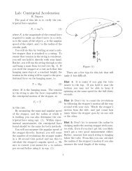
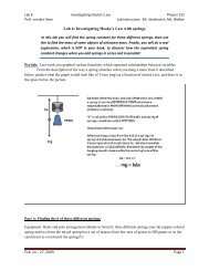
<strong>Hall</strong> <strong>Effect</strong> <strong>Probe</strong> <strong>Calibration</strong> KitInstructionsYour <strong>Hall</strong> <strong>Effect</strong> <strong>Probe</strong> (HE1-A) produces a voltage at its output terminals that is proportional tothe magnetic field imposed at its sensors.* However, the unit is not calibrated. That is, you arenot given the proportionality constant between the output voltage and the magnetic field, thenumber <strong>of</strong> VoltsITesla. It is the job <strong>of</strong> the students to calibrate their own <strong>Hall</strong> <strong>Probe</strong>s.Finding the <strong>Calibration</strong> Equation when using Helmholtz CoilsTo calibrate the <strong>Hall</strong> <strong>Probe</strong>, you need a known magnetic field or, preferably, a known source <strong>of</strong>magnetic fields. Permanent magnets do not fill this need because they are both temperature andtime dependent. Currents, which you have studied, are a well known source <strong>of</strong> magnetic fields.The Biot-Savart law, appropriate for continuous time independent current, allows you tocalculate the magnetic field for various wire configurations. The wire configuration we choosefor this calibration is an identical pair <strong>of</strong> coils mounted so that the separation between the planes<strong>of</strong> the coils is equal to the radius <strong>of</strong> the coils themselves. This geometry produces a very uniformmagnetic field at and around its center region. This uniformity is important for a calibrationfield. It means that the exact location <strong>of</strong> the <strong>Hall</strong> sensor inside the coils is not critical, since themagnetic field is the same over a significant distance. This configuration is called a HelmholtzCoil.The coil should be wound according to the pictorial instructions using the magnet wire supplied.The two windings are to be in series, EACH WITH SAME NUMBER OF TURNS OF WIRE. Itis essential to wind the coils in the same direction; otherwise, the field at the center will be m.Students should use at least ten turns per winding and can use as many as fit in the groove.Higher fields may give better results.Starting with the Biot-Savart law, students can derive the general expression for the magneticfield at the center <strong>of</strong> a set <strong>of</strong> Helmholtz coils. Using the parameters <strong>of</strong> the coil they have wound,they can then find value <strong>of</strong> the field in SI units as a function <strong>of</strong> the current through the coil. In SIunits, the general Helmholtz equation given by the Biot-Savart law will be:In this equation:B = Magnetic Field in TeslaN = # <strong>of</strong> Turns on Each WindingR = Radius in MetersI = Current in AmperesFor the provided coil form R = 2.3 a 10" meters. As an example, we evaluate the calibrationconstant for a coil with N = 15 turnslwinding and the current measured in amperes.B (in tesla) = 0.000587 IB (in millitesla) = 0.587 I* There is also an <strong>of</strong>fset DC voltage which is set by the zero adjust control.
Winding the CoilAny number <strong>of</strong> turns per winding can be used for the for the Helmholtz pair. Students shoulddescribe the advantages <strong>of</strong> their particular choices. A 17 foot length <strong>of</strong> magnet wire issufficient for a 15 turdwinding system. Leaving several inches for connecting to the currentsource, the wire is then threaded through from the inside <strong>of</strong> the coil form, as shown on the nextpage in the Diagranis for Winding the <strong>HECK</strong>1-A Helmholtz Pair. The wire should be keptunder slight tension as the turns are laid into the groove, keeping careful count. The wireshould then be led to the other groove and the turns laid so that the current in both windingswill be going in the same direction.Once the winding is finished, the insulation must be scraped <strong>of</strong>f both ends <strong>of</strong> the wire completelyso that good contact will be made.Doing the <strong>Calibration</strong>The "Helmholtz Pair" can now be used to calibrate both sensors in the <strong>Hall</strong> <strong>Effect</strong> <strong>Probe</strong>Support the coil form on the 2 ?4 " piece <strong>of</strong> PVC pipe provided in the kit. Mount the <strong>Hall</strong> <strong>Effect</strong><strong>Probe</strong> on its non-magnetic stand, and adjust its height so that the sensor rod is level with themiddle <strong>of</strong> the coil forni.The sensors are located 1.0 cm from the end <strong>of</strong> the probe rod. To calibrate the radial sensor, theprobe rod is simply inserted along the axis <strong>of</strong> the coils so that the sensor itself is halfwaybetween the coils. The transverse sensor is calibrated by placing the probe end through the side29/64" hole in the form.Since the area <strong>of</strong> constant field for a Helmholtz Pair is relatively large, a visual location will besufficient. Students should verify this for themselves by moving the sensor back in forth toverify that they are in a region where the field does not change.It is advisable to use a current regulated power supply capable <strong>of</strong> at least one-ampere output.When using 15 turnslwinding, the resistance <strong>of</strong> the coil pair is about 1R. This resistance willchange as the wire heats up during the calibration process. We suggest a current regulatedsupply so that the current will remain constant regardless <strong>of</strong> wire temperature. Teachspinrecommends using the Kenwood PR36-3 supply which can be used in either voltage or currentregulated mode. This supply will produce 3 amps at 36 volts, much more power than needed.At 3 amps, however, the coil dissipates about 10 watts and will get quite warm.While a single point calibration is possible, it will not give the best calibration constant, nor willit convince you that the <strong>Hall</strong> <strong>Probe</strong>'s output is linearly proportional to the magnetic field. Designa plot <strong>of</strong> your data that will both achieve the best value for your calibration constant anddemonstrate that there is a linear relationship between the magnetic field and the output <strong>of</strong> the<strong>Hall</strong> <strong>Effect</strong> Sensor HE1 -A.What effect does the zero <strong>of</strong>fset have on the data? How do you deal with the Earth's magneticfield which is always present? Reversing the current in the coil reverses the direction <strong>of</strong> themagnetic field. Be sure to try it. How can you use the data obtained by reversing the current?Once you have successfully calibrated this instrument, you will know just how reliable yourresults are when using it to make experimental measurements.<strong>Hall</strong> <strong>Effect</strong> <strong>Probe</strong> <strong>Calibration</strong> Kit Instructions 2 <strong>of</strong> 2
Diagrams for Winding the <strong>HECK</strong>1-A Helmholtz PairFigure 1: Hold the coil form so Figure 2: Leaving several inches for Figure 3: Wind the wire up andthat you can see the two grooves connecting to the current source, over the coil form as shown.and the holes through which you thread the rest <strong>of</strong> the wire through the Keeping a slight tension, laywill thread the wire. hole nearest the left edge <strong>of</strong> the coil wire neatly into the groove.form.COUNT CAREFULLYFigure 4: After completing Figure 5: Pull all wire through the Figure 6: Again wind wire updesired number <strong>of</strong> windings, hole and thread out through hole next and over the coil form layingthread wire into hole as shown. to the other groove. wire neatly into the groove.COUNT CAREFULLYFigure 7: After completing the Figure 8: Pull all wire through the Figure 9: Cut this end <strong>of</strong> thedesired number <strong>of</strong> turns, thread hole and thread out through the final wire to the desired length andthe remaining wire through the hole. then strip insulation <strong>of</strong>f bothhole to the right <strong>of</strong> the groove.ends <strong>of</strong> the wire.