FHBER7 SA - scheibe aircraft gmbh
FHBER7 SA - scheibe aircraft gmbh
FHBER7 SA - scheibe aircraft gmbh

Create successful ePaper yourself
Turn your PDF publications into a flip-book with our unique Google optimized e-Paper software.
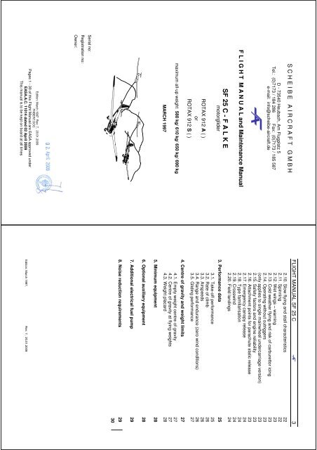
S C H E I B E A I R C R A F T G M B HD - 73540 Heubach, Am Flugplatz 5Tel.: (0)7173 / 184 286 Fax: (0)7173 / 185 587e-mail: info@<strong>scheibe</strong>-<strong>aircraft</strong>.deF L I G H T M A N U A L and Maintenance ManualSF 25 C - F A L K EmotorgliderROTAX 912 A ( )orROTAX 912 S ( )maximum all-up weight 580 kg/ 610 kg/ 650 kg/ 690 kgMARCH 1997Serial no:Registration no:Owner:Edition: March 1997 Rev: 7, 20.01.2009<strong>FHBER7</strong>.DOCPages 1 - 30 of this Flight Manual are EA<strong>SA</strong> approved underEA<strong>SA</strong>.A.C. 11014 dated 02 April 2009This manual is to be kept on board at all timesFLIGHT MANUAL SF 25 C 32.10. Slow flying and stall characteristics 222.11. Spinning 222.12. Wet wings – warning 232.13. Cold weather flying and risk of carburettor icing 232.14. Operating without outriggers 23(only applies to single mainwheel undercarriage version) 232.15. Safety factors and engine reliability 232.16. Attachment points for parachute static release 232.17. Emergency canopy release 242.18. Type familiarisation 242.19. Crosswind 242.20. Field landings 243. Performance data 253.1. Take-off performance 253.2. Rate of climb 263.3. Airspeeds 263.4. Range and endurance (zero wind conditions) 263.5. Gliding performance 274. Centre of gravity and weight limits 274.1. Empty weight centre of gravity 274.2. Centre of gravity at flying weights 274.3. Weight placard 285. Minimum equipment 286. Optional auxiliary equipment 287. Additional electrical fuel pump 298. Noise reduction requirements 2930Edition: March 1997, Rev. 7, 20.01.2009
FLIGHT MANUAL SF 25 C 4Revision status of manualSerialno.Title Pages affected Date Signature1Version of manual - validfor all weight versions.Instructions for use ofvacuum pumpTitle page, insert, 4, 5,7, 10, 12, 13, 15,16,18,25, 26, 27, 2822.01.19982Correction to propellerdrawing forMTV21A-C-F/(CF)175-05Title page, 4, 7, 20, 21,25, 2631.10.19983Additional engine ROTAX912 S ( ) and editingchangeTitle page, insert, 3, 4,5, 6, 7, 8, 9, 10, 11, 12,13, 14, 15, 16, 18, 19,20, 21, 22, 23, 24, 25,26, 2931.01.19994567Following ROTAX SB912-36R1, modification ofprocedure of powersettingfor electr.Constant speed prop;Voltmeter instead ofAmmeterNew Cockpit canopyElectric Trim Servo withPosition indicationJunction change of thepush button switch withone piece canopyIncrease of the MTOWand the max. weight ofnon-lifting partsFM: Title page, 4, 8,13, 16, 19, 26MM: Title page, 10, 18,19FM: Title page, 4, 8,11, 15, 24MM: Title page, 2, 4,15, 19, 21, 27, 28FM: Title page, 4, 8, 16MM: Title page, 18, 19FM: Title page, 3, 4, 5,6, 7, 9, 10, 23, 25, 27,29, 30MM: Title page, 2, 22,23, 24, 25, 26, 27, 28,2915.01.200320.05.200413.10.200520.01.2009Edition March 1997 Revs. 7, 20.01.2009FLIGHT MANUAL SF 25 C 5The pilot is responsible for ensuring that the <strong>aircraft</strong> is operated in accordance with theFlight Manual.The SF25C is authorised to carry a maximum of two adults.The seating is side by side: the pilot sits on the port side.The SF25C is ideal for training. For training purposes the instructor (P1) may sit on eitherside. All regulations must be observed.The starboard control column may be removed for passenger flying.1. Specifications and limitations1.1. EnginesSF 25 C Engines ROTAX 912 A(1)(2)(3)(4), ROTAX 912 S(2)(3)(4)Max. revs 5800 rpm 5800 rpmTake off (full power)(max. 5 min)Max. 5800 rpm59.6 kW (82 PS/80bhp)Max 5800 rpm73.5 kW (100 PS/98bhp)Cruise at Max. 4800 rpm(63 PS/62bhp)Max. 4800 rpm(72 PS/71bhp)and additionally 22 ins manifold pressure (only for variable pitch propellers)Static rpm at full power Min. 5000 rpm ± 100 rpm(Fixed pitch)Min. 5600 rpm ± 100 rpm(Fixed pitch)5600 rpm ± 100 rpm 5600 rpm ± 100 rpm(Variable pitch, fine pitch)Cylinder head temperature max. 120°C max. 120°C1.2. FuelROTAX 912 A ( ) ROTAX 912 S ( )Min. ROZ 90 Min. ROZ 95EN 228 Normal ----EN 228 SUPER EN 228 SUPEREN 228 Super-Plus or EN 228 Super-Plus orAVGAS 100 LL AVGAS 100 LLBecause of the higher lead content of AVGAS thevalve seats are subjected to higher loads andthere is increased carbon formation. ConsequentlyAVGAS should only be used if there are vapourformation problems or if other types of fuel are notavailable. (see also Operating Manual for Rotax912, section 10.2.2)Fuel tank capacity44 l (usable) or55 l (usable) or80 l (79 l usable)Edition: March 1997 Rev: 7, 20.01.2009
FLIGHT MANUAL SF 25 C 61.3. LubricantsBranded engine oils with gear additiveNever use unblended aviation engine oil.Approved oils:Use only API rated SF or SG oils. [Further details in Section 10.2.3) Lubricants inROTAX 912 Operating Manual].Synthetic & semi-synthetic oils should be used in preference as they are moretemperature resistant and produce less residues. NB: If AVGAS 100LL is used, the oil must be changed morefrequently. See Service Information 18 UL 97.Oil capacity 3.0 l (minimum 2.0 l)Oil consumption max. 0.1 l/hrOilpressureROTAX 912 A( ) ROTAX 912 S( )min. 0.8 bar (< 3500 rpm) 0.8 bar (< 3500 rpm)[1.5 bar up to engine serial no. 4,410.266]normal 2.0 – 5,0 bar > 3500 rpm 2.0 – 5,0 bar > 3500 rpm[1.5-5.0 bar up to engine serial no. 4,410.266]max. maximum 7.0 bar ∆ Warning: Permissible for short duration oncold starting.OiltemperatureROTAX 912 A ( ) ROTAX 912 S ( )min. 50°C min. 50°Cmax. 140°C max. 130°Cbest operating temperature approx. 90°C - 110°CEdition: March 1997 Rev: 7, 20.01.2009FLIGHT MANUAL SF 25 C 71.4. Cooling systemSealed cooling system with expansion and overflow vessel. The expansion vesselis sealed with a pressure cap (with excess pressure and blow valve).Coolant: 50% antifreeze with anti-corrosion additives and 50% water, for all yearround operation.(see also ROTAX 912 Operating Manual, Section 10.2.1.)1.5. Propeller1) 2 blade fixed pitch a) Hoffmann HO11AHM-165130 for ROTAX 912 A(1), A(2) and A(4)b) MT-Propeller MT165R130-2A for ROTAX 912 A(1), A(2) and A(4)c) MT-Propeller MT170R135-2A for ROTAX 912 S(2) and S(4)d) MT-Propeller MT175R130-2A for ROTAX 912 S(2) and S(4)2) 2 blade variable pitch a) MT-Propeller MTV1A/175-05 for ROTAX 912A(2), A(4), S(2), S(4)b) MT-Propeller MTV21A-C-F/(CF)175-05 for ROTAX 912A(3), S(3)(factory setting of fine pitch for 912 A = 12°± 0.2°for 912 S = 14°± 0.2°, see propeller card)∆ ROTAX 912 A + variable pitch propeller: Not for max. AUW of 580 kg ∆∆ ROTAX 912 S + fixed or variable pitch propeller: Only for max AUW of 650/ 690 kg ∆1.6. Engine instrumentation and markingsRev counterStarting range 0 – 1400 rpm (yellow arc)Normal operating range 1400 - 4800 rpm (green arc)Caution range 4800 -5800 rpm (yellow arc)Max. revs 5800 rpm (red line)Engine hours counterThe engine hours counter is a revolution counter. Irrespective of the actual rpm itcounts 5000 revolutions as 1 minute of operation. The first three digits representcompleted hours and the last two digits show values for 1/10 and 1/100 of an hourrespectively. If an electronic rev counter without engine hours counter is in use, thenthere must be a separate engine hours counter.Oil pressure gaugeMinimal operating range 0.8 - 2.0 bar (yellow arc)0.8 – 1.5 barNormal operating range 2.0 - 5.0 bar (green arc)1.5 – 5.0 barPermissible for short 5.0 – 7.0 bar (yellow arc)duration on cold startingMaximum oil pressure 7.0 bar (red line)(for ROTAX 912 A, up to engine serial no.4,410.266)(for ROTAX 912 A, up to engine serial no.4,410.266)Oil temperature gauge ROTAX 912 A( ) ROTAX 912 S( )Normal operating range (green arc) 50°- 140°C 50°- 130°CMinimum temperature (red line) 50°C 50°CMaximum oil temperature (red line) 140°C 130°CCylinder head temperatureMaximum cylinder head temperature ROTAX 912 A ROTAX 912 S(red line) 120°C 120°CEdition: March 1997 Rev: 7, 20.01.2009
FLIGHT MANUAL SF 25 C 91.11. Connecting other consumers.Further circuit breakers may be added to the terminal bar for additional consumersThis applies to ACL, nav lights, VOR, transponder, encoder etc. It is important toensure that the additional equipment is using the correct fuse rating.The <strong>aircraft</strong> wiring system is 12 V DC, negative ground.The appropriate regulations must be observed when fitting additional equipment.The fuses on the firewall can be replaced with state of the art circuit breakers.There is then no need for spare fuses and a visual check can be made to see whichsystem has tripped out.The appropriate regulations must be observed when fitting additional equipment.1.12. Airspeed limitations and load factorsThis table shows maximum airspeeds under different conditions:VNEVRAVAVWSpeed IAS CommentKph knotsMaximum speedin calm conditionsMaximumspeedRough airmax. weight580/ 610 kgmax. weight650/ 690 kgmax. weight580/ 610 kgManoeuvringspeed max. weight650/ 690 kgmax. weight580/ 610 kgWinch launchspeeds max. weight650 kg190150160150160100110Never exceed this speed. Controlsurface movements must belimited to one third travel.Do not exceed this speed exceptin calm air conditions and thenonly with caution. See Note 1.See Note 2Only permissible with enginestoppedNote 1: Rough air means conditions which may be encountered in wave rotor, cumulonimbus clouds, whirlwinds and when flying over mountain ridges.Note 2: At speeds in excess of VA do not make full or abrupt control movements, as theycould overstress the <strong>aircraft</strong>.Edition: March 1997 Rev: 7, 20.01.2009FLIGHT MANUAL SF 25 C 10Airspeed indicator markings.Marking Speeds Explanationkph knotsmax. weight80 -150 43-80580/ 610 kgNormal operating range,green arcmax. weightsee Note 380 -160 43-86650/ 690 kgyellow arcmax. weight580/ 610 kgmax. weight650/ 690 kg150 -190 80-102160 -190 86-102red line 190 102blue lineROTAX 912 A 90 49ROTAX 912 S 95 51yellow triangle 90 49Caution rangesee Note 4Maximum permissible speedfor all operating modesBest rate of climbMinimum approach speed atmaximum weightNote 3: The lower limit applies to maximum weight and most forward CG position. (VS1 isthe minimum speed with spoilers extended)The upper limit is the maximum rough air speed.Note 4: In this range manoeuvres must be conducted with caution and only in calmair conditions.∆ Warning: The following loads must not be exceeded when flying accurately:With spoilers closedat manoeuvring speed: (150 kph = 80 knots) +5.3gat maximum speed (190 kph = 102 knots) +4.0gWith spoilers extended +3.5g1.13. WeightsEmpty weight (dependent on type of undercarriage andequipment)approx. 400kg–450kgPermissible load including fuel approx. 200kgMaximum permissible AUW (all up weight) *) 580kg/ 610kg/ 650kg/ 690 kgMaximum weight of non-lifting components *) 430kg/ 450kg/ 490kg/ 530 kg*) Delete as appropriateSee Maintenance Manual pp. 24 and 25Edition: March 1997 Rev: 7, 20.01.2009
FLIGHT MANUAL SF 25 C 232.12. Wet wings – warningThe SF 25 C uses a modern glider wing section so it is sensitive to rain on the wings.The airflow over the wings is disturbed by the rain drops, which reduces the liftavailable. With dry wings the minimum speed is 38 knots, but with wet wings it isabout 44 – 46 knots. The stall characteristics are also affected. With dry wings, theSF 25 C is good-natured in a stall, but with wet wings it can drop a wing. Whenflying in rain, always fly at speeds greater than 46 knots. When taking off with wetwings, never lift off at less than 46 knots. Climb and approach at about 57 knots.Avoid steep turns and other high g force manoeuvres. Any snow or ice/ white ice onthe wings must always be removed before take-off. Don’t forget to clean off thetailplane too.2.13. Cold weather flying and risk of carburettor icingAt all times of the year and especially during the cooler seasons it is important tomonitor that the engine oil temperature never drops below 70° C. Intermediatesettings on the cowl flap (infinitely adjustable) are effective in controlling the coolingair reaching the engine. Always ensure that the maximum cylinder headtemperature never exceeds 120°C (ROTAX 912 A and ROTAX 912 S).2.14. Operating without outriggers(only applies to single mainwheel undercarriage version)The SF 25 C can also be operated without the outriggers fitted. You can taxi with awing tip holder. At take-off an assistant must run with the wing tip until the aileronsbecome effective. When landing the SF 25 C can be held level with ailerons virtuallyuntil it has stopped.2.15. Safety factors and engine reliabilityNever forget that any motor glider engine is designed to simpler approvalspecifications than other aero engines. Consequently motor glider engines aresimpler and cheaper, so always plan your route with safety in mind and maintain thenecessary safety heights. You should always fly within gliding reach of a good fieldlanding opportunity.2.16. Attachment points for parachute static releaseThe static release cords for automatic parachutes are hooked on to the tubularmember above the seat back near the red mark, port for the port seat and starboardfor the starboard seat.Edition: March 1997 Rev. 7: 20.01.2009FLIGHT MANUAL SF 25 C 253. Performance dataThe specifications in this section refer to the following propellers:HO11AHM-165 130, MT165R130-2A, MT170R135-2A or MT175R130-2AMTV1A/175-05 and MTV21A-C-F/(CF)175-05.3.1. Take-off performanceThese performance figures were obtained from type test results and can bereproduced provided that the motor glider and engine are in good condition and thatthe pilot is of average ability and skillMaximum permissible AUW *) 580 kg 610 kg 650 kg 690 kg*) Delete as appropriateLevel airfield with short grass in normal condition. Dry wings with a smooth surface. No windconditions. Air pressure corresponding to normal pressure at airfield height.Lift off speed approx. 38 knots,Climb speed 49 – 51 knots.For take-off from a hardsurfaced runway all valuesmay be reduced by about 5%Airfield heightabovesea levelAir temperature at ground level in °CTake-off runin mup to lift off-15 0°C +15°C +30°Cm ft m m m m025050075010000820164024603280105113123133145122132143155168141152165178193160174189205221Total take-off distancein mto clear 15 m obstruction025050075010000820164024603280216229242257273241255271288306268285303320342297315334362391This table applies to all previously quoted engine/propeller combinations and to all <strong>aircraft</strong> weights.Values for ground run and take-off over a 15 m obstacle are the same as or better than those in thetable for the variable pitch propeller and /or the ROTAX 912 S engine.Edition: March 1997 Rev. 7: 20.01.2009
FLIGHT MANUAL SF 25 C 273.5. Glide performanceWith engine stopped, cowl flap closed, clean wings and (if fitted) Variable pitch propin glide configurationMinimum rate of sink at 43 knots (single mainwheel undercarriage) 1.12 m/secMinimum rate of sink at 43 knots (two wheel undercarriage) 1.18 m/secMinimum rate of sink at 43 knots (tricycle undercarriage) 1.17 m/secBest glide at 49 knots (single mainwheel undercarriage) 1: 22The values are improved somewhat when the variable pitch propeller is set to glideconfiguration.4. Centre of gravity and weight limits Caution It is the responsibility of the pilot (P1) to ensure that the weight limitsare observed.4.1. Empty weight centre of gravityAlways ensure that the empty weight CG remains within the permitted limits, forexample after major repairs, the installation of additional equipment or repainting. Ifnecessary, ballast weights must be fitted. Should this occur, a suitably qualifiedinspector must be called in. Permitted empty weight CG range (see MaintenanceManual, pp 23-24).Aircraft position: Wing chord at rib 6 (2.2 m / 86.61” from the centre line) =horizontal.Datum: 2.0 m / 78.74” ahead of the leading edge of rib 0 (root rib),0.52m / 20.47” from centre line.If the empty weight CG is kept within the approved empty weight CG range,compliance with the loading chart will ensure that the flying weight CG willautomatically remain within its permitted range.4.2. Centre of gravity at flying weightsIn flight the centre of gravity has a considerable influence on the handling qualities ofthe <strong>aircraft</strong>. For this reason it is of vital importance that the prescribed CG limits arescrupulously observed.The following limits of CG flying weights have been tested and approved:Applicable to: Flying weights of 580 kg, 610 kg, 650 kg and 690 kg.max forward CG 2,143 m / 84.37” aft of datummax. aft position of CG: 2.334 m / 91.87” aft of datumEdition: March 1997 Rev. 7, 20.01.2009FLIGHT MANUAL SF 25 C 297. Additional electrical fuel pump(Optional version TM 653-51/ 2)An additional electric fuel pump can be installed in the motor glider as an option.This can be used for added safety:a) before starting the motorb) for take-offc) for the approach and the possibility of a touch and god) in flight when the fuel supply may be less reliable e.g. through vapourformation at altitude, during very hot weather and in particular when climbingsteeply. In normal cruise the optional electric fuel pump can be switched off.When the additional fuel pump is switched on a special warning light comeson. Please note however that this does not give any indication of the actualfuel pressure.8. Noise reduction requirementsOnly German national noise limits for: Section X Section: VISF 25 Cwith the following engine /propeller combinationsROTAX 912 A(1), A(2) or A(4)MT165R130-2AHO11AHM-165 130ROTAX 912 A(2) or A(4)MTV1A/175-05Max.flyingweightNoise limit forenhanced noiseabatementUp to builddate31.121999From builddate2000Calculatednoiselevel580 kg XXX XXX XXX610 kg XXX XXX XXX650 kg65.6dB(A)690 kg XXX610 kg650 kg64.9dB(A)65.6dB(A)63.6dB(A)62.9dB(A)63.6dB(A)60.7dB(A)55.3dB(A)55.3dB(A)Noise limit forenhanced noiseabatementUp to builddate31.12199960.0dB(A)60.1dB(A)60.7dB(A)From builddate200058.0dB(A)58.1dB(A)58.7dB(A)Calculatednoiselevel50.4dB(A)50.8dB(A)52.1dB(A)ROTAX 912 A(3)MTV21A-C-F/(CF)175-05690 kg XXX610 kg650 kg64.9dB(A)65.6dB(A)62.9dB(A)63.6dB(A)55.3dB(A)55.3dB(A)690 kg XXXEdition March 1997 Rev. 7: 20.01.2009
FLIGHT MANUAL SF 25 C 30Only German national noise limits for: Section XSF 25 Cwith the following engine / propellercombinationsMax.flyingweightNoise limit forenhanced noiseabatementUp tobuild date31.121999From builddate2000Calcula-tednoise levelROTAX 912 S(2) oder S(4)MT170R135-2A 690 kg650 kg 55,4dB(A)ROTAX 912 S(2) oder S(4)MT175R130-2A 690 kg65,6dB(A)ROTAX 912 S(2) oder A(4)MTV1A/175-05 690 kgROTAX 912 S(3)MTV21A-C-F/(CF)175-05 690 kg650 kg 55,6dB(A)63,6dB(A)650 kg 57,5dB(A)650 kg 57,5dB(A)Enhanced German national noise abatement requirements will be met if the measured noiselevel is within the maximum values prescribed in Annex 2 of the airfield noise abatementregulation by the following amounts:in Section VI in Section Xfor build date before 1 January 2000 by: min. 4 dB(A) min. 5 dB(A)and for build dates from 1 January 2000 by: min. 6 dB(A) min. 7 dB(A)These values have been incorporated in the table above.Edition March 1997 Rev. 7: 20.01.2009