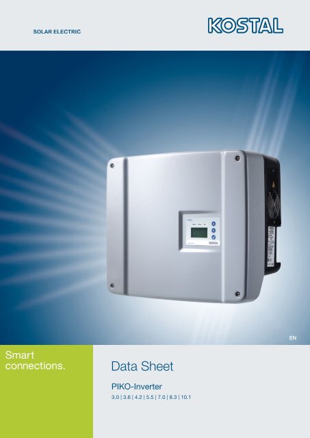
Datasheet PIKO 3.0
Datasheet PIKO 3.0
Datasheet PIKO 3.0
You also want an ePaper? Increase the reach of your titles
YUMPU automatically turns print PDFs into web optimized ePapers that Google loves.
ENData Sheet<strong>PIKO</strong>-Inverter<strong>3.0</strong> | 3.6 | 4.2 | 5.5 | 7.0 | 8.3 | 10.1
Table of content4 Overview technical dataInverter single-phase5 Inverter <strong>PIKO</strong> <strong>3.0</strong>5 Inverter <strong>PIKO</strong> 3.6Inverter three-phase6 Inverter <strong>PIKO</strong> 4.26 Inverter <strong>PIKO</strong> 5.57 Inverter <strong>PIKO</strong> 7.07 Inverter <strong>PIKO</strong> 8.37 Inverter <strong>PIKO</strong> 10.18 Country intercompatibility of <strong>PIKO</strong>-Inverters8 Standards and guidelines for <strong>PIKO</strong>-Inverters9 Country-specific switch-off limits10 Terms04/2012 edition, subject to technical changes and printing errors.Current information can be found at www.kostal-solar-electric.com3
Overview Technical Data<strong>PIKO</strong> <strong>3.0</strong> <strong>PIKO</strong> 3.6 <strong>PIKO</strong> 4.2 <strong>PIKO</strong> 5.5 <strong>PIKO</strong> 7.0 1 <strong>PIKO</strong> 8.3 1 <strong>PIKO</strong> 10.1 1Input side (DC)Number of DC inputs / of MPPtrackers1 / 1 2 / 2 2 / 2 3 / 3 2 / 2 2 / 2 3 / 3Max. recommended DC power 5 -10% above rated AC output 2Max. DC input voltage(open circuit voltage)950 VMin. DC input voltage180 VMax. DC input current 9 A 9 A / 13 A 3 9 A 12,5 A / 25 A 3Max. DC input current withparallel connection– 13 A – 25 A4Output side (AC)Number of feed-in phases 1 3AC grid voltage 1/N/PE, AC, 230 V 3/N/PE, AC, 230 /400 VMax. AC output current 13,1 A 15,7 A 6,1 A 8 A 10,2 A 12 A 14,5 AShort-circuit current 21,6 A 10,2 A 21 ARated AC output (cosφ = 1)<strong>3.0</strong>00 W3.600 W(ES: 3.300 W,PT: 3.300 W)4.200 W(UK: 4.000 W,PT1: 3.680 W,PT2: 3.450 W)5.500 W(ES: 5.000 W,PT: 5.000 W)7.000 W(DK: 6.000 W)8.300 W 10.000 WMax. AC apparent power(cosφ, adj)<strong>3.0</strong>00 VA 3.600 VA 4.200 VA 5.500 VA 7.000 VA 8.300 VA 10.000 VAMax. efficiency 95,7 % 95,8 % 96,5 % 96,2 % 96,0 % 97,0 % 97,0 %European-standard efficiency 95,0 % 95,1 % 95,4 % 95,7 % 95,3 % 96,3 % 96,4 %Rated frequencySelf-consumption at nightProtection class50 HzInverter < 1 W, Communicationboard < 1,7 WGalvanic isolationTransformerlessSetting range of the power factorcosφ AC,r0,95 capacitive... 1 ... 0,95 inductive 0,9 capacitive ... 1 ... 0,9 inductiveType of grid monitoringAccording to the countries‘ certificatesReverse polarity protectionPersonal protectionOperational conditions, ingressprotection according to IEC 60529Ambient temperatureIShort circuit diode at DC sideUniversal current sensitive residual current circuit breaker and earth fault monitoringinterior + exterior, IP 55-20° ... 60° CMax. humidity 0 ... 95 %Type of coolingRegulated ventilationCommunications interfacesEthernet RJ45 (2 x with Communicationboard 2, incl. integrated switch),RS485, S0, 4 x analogue inputsMax. sound< 33 dB(A)Ventilator 25% -> 33 dB(A)Ventilator 50% -> 41 dB(A)Ventilator 75 ... 100% -> 46 dB(A)Connection technology at input side MC 4Connection technology at output sideSpring-loaded terminal stripDimensions (W x D x H) 420 x 211 x 350 mm 520 x 230 x 450 mmWeight 19,8 kg 20 kg 20,5 kg 21,1 kg 33 kg 33 kg 34 kgDisconnection device1This inverter is available in two versions: with or without arc detection2depending on ambient temperature and solar radiation³ with parallel connection of two MPP trackersIntegrated electronic circuit breaker
Inverter <strong>PIKO</strong> <strong>3.0</strong> | 3.6• Single-phase feed-in• Transformerless topology• Extension of the input current range possible• Integrated circuit contact for self-consumption control• Integrated electronic DC circuit breaker• Integrated data logger and web server for system monitoring• Various communication interfaces included as standard:Ethernet, RS485, S0, 4 x analogue inputsTechnical Data<strong>PIKO</strong> <strong>3.0</strong> <strong>PIKO</strong> 3.6Input side (DC)Number of DC inputs / number of MPP trackers 1 / 1 2 / 2Max. input voltage (open circuit voltage) U dcmax950 V 950 VMin. DC input voltage U dcmin180 V 180 VStart-up DC input voltage U dcstart180 V 180 VRated DC input voltage U DC,r680 V 680 VMax. MPP voltage U MPPmax850 V 850 VMin. MPP voltage in single-tracker operation U MPPmin380 V 440 VMin. MPP voltage in two-tracker or parallel operation U MPPmin– 340 VMax. DC input current I dcmax9 A 9 AMax. DC input current with parallel connection I dcmax,p– 13 AOutput side (AC)Number of feed-in phases 1 1AC grid voltage U AC,r1/N/PE, AC, 230 VMax. AC output current I Acmax13,1 A 15,7 AShort-circuit current I sc21,6 A 21,6 ARated AC output (cosφ = 1) P AC,r<strong>3.0</strong>00 W3.600 W (ES: 3.300 W,PT: 3.300 W)Max. AC apparent power (cosφ, adj) S AC<strong>3.0</strong>00 VA 3.600 VAPower factor cosφ ACr0,95 capacitive ... 1 ... 0,95 inductiveMax. efficiency η max95,7 % 95,8 %European-standard efficiency η EU95,0 % 95,1 %Rated frequency ƒ r50 Hz 50 Hz97P ac,rEfficiency rate characteristic curves <strong>PIKO</strong> <strong>3.0</strong> Efficiency rate characteristic curves <strong>PIKO</strong> 3.6%%970% 20% 40% 60% 80% 100% P ac,r0% 20% 40% 60% 80% 100%969594939291908988878695,7 % MAXU DC,r= 680 V, single stringU MPPmax= 850 V, single stringU MPPmin= 380 V, single string969594939291908988878695,8 % MAXU DC,r= 680 V, single stringU MPPmax= 850 V, single stringU MPPmin= 340 V, 2 parallel stringsP acP ac5
Inverter <strong>PIKO</strong> 4.2 | 5.5• Three-phase feed-in• Transformerless topology• Extension of the input current range possible (<strong>PIKO</strong> 4.2)• Three independent MPP trackers (<strong>PIKO</strong> 5.5)• Integrated circuit contact for self-consumption control• Integrated electronic DC circuit breaker• Integrated data logger and web server for system monitoring• Various communication interfaces included as standard:Ethernet, RS485, S0, 4 x analogue inputsTechnical Data<strong>PIKO</strong> 4.2 <strong>PIKO</strong> 5.5Input side (DC)Number of DC inputs / number of MPP trackers 2 / 2 3 / 3Max. input voltage (open circuit voltage) U DCmax950 V 950 VMin. DC input voltage U DCmin180 V 180 VStart-up DC input voltage U DCstart180 V 180 VRated DC input voltage U DC,r680 V 680 VMax. MPP voltage U MPPmax850 V 850VMin. MPP voltage in single-tracker operation U MPPmin500 V 660 VMin. MPP voltage in two-tracker or parallel operation U MPPmin360 V 360 VMax. DC input current I DCmax9 A 9 AMax. DC input current with parallel connection I DCmax,p13 A –Output side (AC)Number of feed-in phases 3 3AC grid voltage U AC,r3/N/PE, AC, 230 V / 400 VMax. AC output current I ACmax6,1 A 8 AShort-circuit current I sc10,2 A 10,2 ARated AC output (cosφ = 1) P AC,rPT1: 3.680 W,4.200 W (UK: 4.000 W,PT2: 3.450 W)Efficiency rate characteristic curves <strong>PIKO</strong> 4.2 Efficiency rate characteristic curves <strong>PIKO</strong> 5.55.500 W(ES: 5.000 W,PT: 5.000 W)Max. AC apparent power (cosφ, adj) S AC4.200 VA 5.500 VAPower factor cosφ ACr0,9 capacitive ... 1 ... 0,9 inductiveMax. efficiency η max96,5 % 96,2 %European-standard efficiency η EU95,4 % 95,7 %Rated frequency ƒ r50 Hz 50 Hz%%96,5 %97MAX9796,2% MAX0% 20% 40% 60% 80% 100%P ac,r0% 20% 40% 60% 80% 100%9695949392919089888786U DC,r= 680 V, single stringU MPPmax= 850 V, single stringU MPPmin= 360 V, 2 parallel strings9695949392919089888786U DC,r= 680 V, single stringU MPPmax= 850 V, single stringU MPPmin= 360 V, 2 parallel stringsP acP acP ac,r6
Inverter <strong>PIKO</strong> 7.0 | 8.3 | 10.1• Three-phase feed-in; Transformerless topology• Extension of the input current range possible• With or without arc detection• Three independent MPP trackers (<strong>PIKO</strong> 10.1)• Integrated circuit contact for self-consumption control• Integrated electronic DC circuit breaker• Integrated data logger and web server for system monitoring• Various communication interfaces included as standard:Ethernet, RS485, S0, 4 x analogue inputs• Graphic display with 3-button controlTechnical Data<strong>PIKO</strong> 7.0 <strong>PIKO</strong> 8.3 <strong>PIKO</strong> 10.1Input side (DC)Number of DC inputs / number of MPP trackers 2 / 2 2 / 2 3 / 3Max. input voltage (open circuit voltage) U DCmax950 V 950 V 950 VMin. DC input voltage U DCmin180 V 180 V 180 VStart-up DC input voltage U DCstart180 V 180 V 180 VRated DC input voltage U DC,r680 V 680 V 680 VMax. MPP voltage U MPPmax850 V 850 V 850 VMin. MPP voltage in single-tracker operation U MPPminnot recommendedMin. MPP voltage in two-tracker or parallel operation U MPPmin400 V 400 V 420 VMax. DC input current I DCmax12,5 A 12,5 A 12,5 AMax. DC input current with parallel connection I DCmax,p25 A 25 A 25 AOutput side (AC)Number of feed-in phases 3 3 3AC grid voltage U AC,r3/N/PE, AC, 230 V / 400 VMax. AC output current I Acmax10,2 A 12 A 14,5 AShort-circuit current I sc21 A 21 A 21 A7.000 WRated AC output (cosφ = 1) P AC,r8.300 W 10.000 W(DK: 6.000 W)Max. AC apparent power (cosφ, adj) S AC7.000 VA 8.300 VA 10.000 VAPower factor cosφ ACr0,9 capacitive ... 1 ... 0,9 inductiveMax. efficiency η max96,0 % 97,0 % 97,0 %European-standard efficiency η EU95,3 % 96,3 % 96,4 %Rated frequency ƒ r50 Hz 50 Hz 50 HzEfficiency rate characteristic curves<strong>PIKO</strong> 7.0%97969594939291908988878696,0 %MAXU DC,r= 680 V, 2 parallel stringsU MPPmax= 850 V, 2 parallel stringsU MPPmin= 400 V, 2 parallel stringsEfficiency rate characteristic curves<strong>PIKO</strong> 8.3%979695949392919089888786%97 %MAX 979695949392919089U DC,r= 680 V, 2 parallel strings88U MPPmax= 850 V, 2 parallel strings87U MPPmin= 400 V, 2 parallel strings 86Efficiency rate characteristic curves<strong>PIKO</strong> 10.197 %MAXU DC,r= 680 V, 2 parallel stringsU MPPmax= 850 V, 2 parallel stringsU MPPmin= 420 V, 2 parallel strings0% 20% 40% 60% 80% 100%P acP ac,r0% 20% 40% 60% 80% 100%P acP ac,r0% 20% 40% 60% 80% 100%P acP ac,r7
Country intercompatibility of <strong>PIKO</strong>-Inverters<strong>PIKO</strong> <strong>3.0</strong> <strong>PIKO</strong> 3.6 <strong>PIKO</strong> 4.2 <strong>PIKO</strong> 5.5 <strong>PIKO</strong> 7.0 <strong>PIKO</strong> 8.3 <strong>PIKO</strong> 10.1name plate: Par/PIB ≥DE 1 Germany 01.00 02.00 0<strong>3.0</strong>4 01.03 – 0<strong>3.0</strong>0 01.00DE NSRGermany P(f) 2and cosφ(P) 3 01.09 02.09 03.18 01.19 10.0 03.15 01.16DE MSR Germany incl. LVRT 4 – – – – 10.0 03.13 01.12AT Austria 01.04 02.04 03.13 01.14 10.0 0<strong>3.0</strong>7 01.06CH Switzerland 01.00 02.00 0<strong>3.0</strong>4 01.03 10.0 0<strong>3.0</strong>0 01.00FR France 01.00 02.00 0<strong>3.0</strong>4 01.03 10.0 0<strong>3.0</strong>0 01.00LU Luxembourg 01.00 02.00 0<strong>3.0</strong>4 01.03 10.0 0<strong>3.0</strong>0 01.00BE Belgium 01.00 02.00 0<strong>3.0</strong>4 01.03 10.0 0<strong>3.0</strong>0 01.00NL Netherlands 01.00 02.00 0<strong>3.0</strong>4 01.03 10.0 0<strong>3.0</strong>0 01.00IT Italy 01.00 02.00 0<strong>3.0</strong>4 01.03 10.0 0<strong>3.0</strong>0 01.00ES Spain 01.00 02.00 0<strong>3.0</strong>4 01.03 10.0 0<strong>3.0</strong>0 01.00PT Portugal 01.00 02.00 0<strong>3.0</strong>4 01.03 10.0 0<strong>3.0</strong>0 01.00GR Greece (mainland) 01.00 02.00 0<strong>3.0</strong>4 01.03 10.0 0<strong>3.0</strong>0 01.00GR, CYGreece (islands),Cyprus (EU)01.00 02.00 0<strong>3.0</strong>4 01.03 10.0 0<strong>3.0</strong>0 01.00CZ Czech Republic 01.00 02.00 0<strong>3.0</strong>4 01.03 10.0 0<strong>3.0</strong>0 01.00SI Slovenia 01.06 02.06 03.15 01.16 10.0 03.11 01.10BA, BG,EE, HR,LV, LT,ME, RO,RS, SK,TRBosnia and Herzegovina,Bulgaria, Estonia, Croatia,Latvia, Lithuania,Montenegro, Romania,Serbia, Slovakia, Turkey01.06 02.06 03.15 01.16 10.0 03.11 01.10UK, MT United Kingdom, Malta 01.06 02.06 03.18 01.19 – – –DK Denmark 01.09 02.09 03.18 01.19 10.0 03.15 01.16SE Sweden 01.09 02.09 03.18 01.19 10.0 03.15 01.16PL Poland 01.09 02.09 03.18 01.19 10.0 03.15 01.161Only permitted for inverters that are installed in PV systems that have been connected to the mains grid prior to 31 December 2011.2P(f) = Frequency-dependent active power reduction3cosφ (P) = reactive power control4LVRT = Low Voltage Ride Through (only for communication board II)Standards and guidelines for <strong>PIKO</strong>-Inverters *DIN VDE 0100-712; IEC 60364-7-712; CEI 64-8/7; DIN EN 61000-3-2:2006; DIN EN 61000-3-3:1995 + A1:2001 + A2:2005; DIN EN61000-6-2:2005; DIN EN 61000-6-3:2007; DIN EN 50178:1998; DIN V VDE V 0126-1-1 (VDE V 0126-1-1):2006-02, „Eigenerzeugungsanlagenam Niederspannungsnetz“, 4. Ausgabe 2001; BDEW-TR Erzeugungsanlagen am Mittelspannungsnetz, Ausgabe Juni2008; VDE-AR-N 4105, „Erzeugungsanlagen am Niederspannungsnetz“; ÖVE/ÖNORM E 8001-4-712:2009-12, Anhang A (AT); EN50438:2007; RD 1699/2011; RD 661/2007; C10/11-2009.05; G83/1-1; G59/2; ENEL DK 5940 Ed.2.2; IEC 60947-3:1999 + Corrigendum:1999+ A1:2001 + Corrigendum 1:2001 + A2:2005; DIN EN 60947-3; VDE 0660-107:2006-03; IEC 60364-7-712:2002-05;DIN VDE 0100-712:2006-06; TF 3.2.1* For all current certificates see www.kostal-solar-electric.com/download-en in the download area.8


