26.7 mm - Schempp-Hirth
26.7 mm - Schempp-Hirth
26.7 mm - Schempp-Hirth

You also want an ePaper? Increase the reach of your titles
YUMPU automatically turns print PDFs into web optimized ePapers that Google loves.
SCHEMPP-HIRTH<br />
Flugzeugbau GmbH.<br />
Kirchheim/Teck<br />
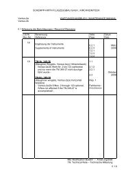
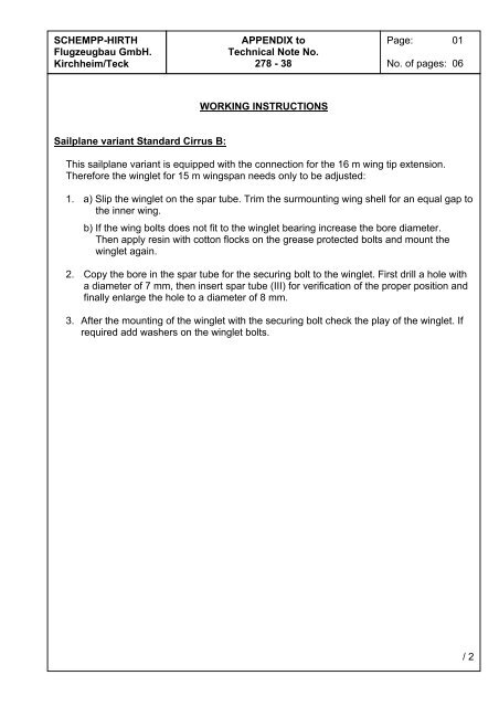
Sailplane variant Standard Cirrus B:<br />
APPENDIX to<br />
Technical Note No.<br />
278 - 38<br />
WORKING INSTRUCTIONS<br />
Page: 01<br />
No. of pages: 06<br />
This sailplane variant is equipped with the connection for the 16 m wing tip extension.<br />
Therefore the winglet for 15 m wingspan needs only to be adjusted:<br />
1. a) Slip the winglet on the spar tube. Trim the surmounting wing shell for an equal gap to<br />
the inner wing.<br />
b) If the wing bolts does not fit to the winglet bearing increase the bore diameter.<br />
Then apply resin with cotton flocks on the grease protected bolts and mount the<br />
winglet again.<br />
2. Copy the bore in the spar tube for the securing bolt to the winglet. First drill a hole with<br />
a diameter of 7 <strong>mm</strong>, then insert spar tube (III) for verification of the proper position and<br />
finally enlarge the hole to a diameter of 8 <strong>mm</strong>.<br />
3. After the mounting of the winglet with the securing bolt check the play of the winglet. If<br />
required add washers on the winglet bolts.<br />
/ 2
SCHEMPP-HIRTH<br />
Flugzeugbau GmbH.<br />
Kirchheim/Teck<br />
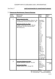
APPENDIX to<br />
Technical Note No.<br />
278 - 38<br />
Sailplane variants<br />
Standard Cirrus, Standard Cirrus G, Standard Cirrus CS 11-75L<br />
Page: 02<br />
No. of pages: 06<br />
These sailplane variants feature no connection for a 16 m wing tip extension. Therefore the<br />
connections for the winglets must be retrofitted.<br />
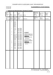
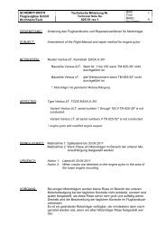
1. Mark wing tip cut-off line according the sketch shown on page 03.<br />
Then cut off the wing tip.<br />
2. a) Mount wing rib (I) with suspension bolts on the spar tube (III) and mount winglet.<br />
b) Fit wing rib (I) see page 06 to wing structure until the winglet matches the wing<br />
contour.<br />
c) If required remove and chamfer the foam.<br />
3. a) Position the wing with winglet with the aid of template “A” (dimensions see page 04<br />
and the photo on page 05). Fit the winglet with rib in the wing that the toe angle of<br />
the winglet matches the template “A” respective refer to drawing on page 06.<br />
b) Adjust the angle of the trailing edges of the wing and winglet with the aid of the<br />
template “B” see also photo on page 05.<br />
c) Damaged GFRP-cloth of the inner sandwich shell should be replaced by a 92125<br />
diagonal.<br />
d) After curing of the inner sandwich laminate check again the position of the winglet<br />
with the aid of the templates “A” and “B”.<br />
4. Bond end rib (I) to wing structure using thickened resin with winglet held in proper<br />
position by the templates “A” and “B”.<br />
5. After curing and tri<strong>mm</strong>ing bond the wing suspension bolts in the wing rib (I).<br />
6. Fit end rib (II) to wing tip cut off previously.<br />
Thereafter insert spar tube (III) into GFRP tube on end rib (I), slide end rib (II) onto<br />
spar tube (III).<br />
Finally bond wing tip to end rib (II) (using thickened resin) - make sure that tip matches<br />
the wing contour.<br />
7. Drill hole (IV) (which takes up the locking pin in the winglet) through the wing structure<br />
(first drill a hole with a diameter of 7 <strong>mm</strong>, then insert spar tube (III) for verification of the<br />
proper position and finally enlarge the hole to a diameter of 8 <strong>mm</strong>).<br />
8. Insert spar tube (III) into winglet and let the locking pin engage.<br />
9. Bond spar tube (III) with winglet (securing bolt engaged) with resin and cotton flocks in<br />
wing rib (I).<br />
10. Copy the bore in the spar tube for the securing bolt to the wing tip. Drill first with 7 <strong>mm</strong>,<br />
check the position of the hole then enlarge the hole to a diameter of 8 <strong>mm</strong>.<br />
10. Do the paint work (if necessary).<br />
/ 3
SCHEMPP-HIRTH<br />
Flugzeugbau GmbH.<br />
Kirchheim/Teck<br />
cut-off line perpendicular<br />
to upper surface of wing<br />
94.13°<br />
APPENDIX to<br />
Technical Note No.<br />
278 - 38<br />
90°<br />
90°<br />
reference line<br />
200 <strong>mm</strong><br />
[7.87 in.]<br />
<strong>26.7</strong> <strong>mm</strong><br />
[1.05 in.]<br />
outwards from<br />
90° reference line<br />
cutting edge<br />
wing tip<br />
200 <strong>mm</strong><br />
[7.87 in.]<br />
Page: 03<br />
No. of pages: 06<br />
/ 4
SCHEMPP-HIRTH<br />
Flugzeugbau GmbH.<br />
Kirchheim/Teck<br />
50 <strong>mm</strong><br />
[1.97 in.]<br />
winglet toe angle stop<br />
100 <strong>mm</strong><br />
[3.94 in.]<br />
400 <strong>mm</strong><br />
[15.75 in.]<br />
Template "B"<br />
(trailing edge)<br />
winglet toe angle stop<br />
WINGLET-MOUNTING TEMPLATES<br />
APPENDIX to<br />
Technical Note No.<br />
278 - 38<br />
86°<br />
Template "A"<br />
wing leading edge stop<br />
Template "B" (trailing edge)<br />
420 <strong>mm</strong><br />
[16.54 in.]<br />
566<br />
[22.28 in.]<br />
93°<br />
450 <strong>mm</strong><br />
[17.72. in.]<br />
450 <strong>mm</strong><br />
[17.72 in.]<br />
Page: 04<br />
No. of pages: 06<br />
120 <strong>mm</strong><br />
[4.72 in.] 379.5 <strong>mm</strong><br />
[14.94 in.]<br />
winglet toe angle stop<br />
Template "A" (port wing)<br />
(bottom side for starboard wing)<br />
86°<br />
200 <strong>mm</strong><br />
[7.87 in.]<br />
406 <strong>mm</strong><br />
[15.98 in.]<br />
wing leading edge stop<br />
900 <strong>mm</strong><br />
[35.43 in.]<br />
/ 5
SCHEMPP-HIRTH<br />
Flugzeugbau GmbH.<br />
Kirchheim/Teck<br />
Template "B"<br />
(trailing edge)<br />
APPENDIX to<br />
Technical Note No.<br />
278 - 38<br />
winglet toe angle stop<br />
Template "A"<br />
Page: 05<br />
No. of pages: 06<br />
wing leading edge stop<br />
/ 6
SCHEMPP-HIRTH<br />
Flugzeugbau GmbH.<br />
Kirchheim/Teck<br />
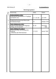
Outboard wing with removable standard wing tip Outboard wing with removable winglet<br />
toe angle - wing leading edge/<br />
tangent line to lower surface of winglet profile<br />
86°<br />
IV<br />
65<br />
III<br />
A B<br />
IV<br />
I<br />
APPENDIX to<br />
Technical Note No.<br />
278 - 38<br />
II<br />
65 <strong>mm</strong><br />
[2.56 in.]<br />
V<br />
Ø8 <strong>mm</strong><br />
[Ø0.31 in.]<br />
spar tube locking pin<br />
Page: 06<br />
No. of pages: 06<br />
SECTION A-B