Lasting Jack Do It Yourself
Lasting Jack Do It Yourself
Lasting Jack Do It Yourself

You also want an ePaper? Increase the reach of your titles
YUMPU automatically turns print PDFs into web optimized ePapers that Google loves.
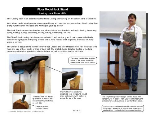
Floor Model <strong>Jack</strong> Stand<strong>Lasting</strong> <strong>Jack</strong> Plans - DIYThe “<strong>Lasting</strong> <strong>Jack</strong>” is an essential tool for Hand <strong>Lasting</strong> and working on the bottom parts of the shoe.With a floor model stand you can move around freely and exercise your whole body. Much better thansitting hunched over on a stool and working on your lap all day.The <strong>Jack</strong> Stand secures the shoe last and allows both of your hands to be free for lasting, inseaming,soling, welting, pulling, cementing, nailing, cutting, hammering, etc. etc...The ShoeSchool <strong>Lasting</strong> <strong>Jack</strong> is constructed with 2” x 4” vertical grain fir, each piece individuallyselected for tight grain and quality. Sealed with a hand rubbed finish to protect the wood for manyyears of service.The universal design of the leather covered “Toe Cradle” and the “Threaded Heel Pin” will adapt to fitmost any size or heel height of shoe or boot last. The angled design detail on the top of the longmovable post which supports the adjustable heel pin, will accept the shaft of tall boots.The most comfortable workingheight of the stand should beabout where your elbow bends.Threaded Heel Pin adjustsup or down to accept anysize or heel height of shoeor boot last.Note the angles cuton top of the post.© Copyright June 2011 ShoeSchool. All Rights Reserved.The Padded “Toe Cradle” issculptured on a compound curvedangle and covered with leather toprotect the toe of the shoe.PAGE 1This simple inexpensive design can be made withstandard 2” x 4” boards from your local lumber yardand common parts available at any hardware store.Traditionally you will see photos of some of the old timeShoemakers who would sit hunched over on a chair orstool and hold the shoe in their lap between their legs.
<strong>Jack</strong> Stand - Instructions for UseAdjustable PinCan be adjusted by screwingin or out to fit any heel heightof shoe or boot last.Sculptured Toe Restwith Leather PaddingWhen properly adjusted the toewill rest gently on the leather pad.For very soft leather shoes youmay want to use a soft cottoncloth for extra protection on theleather pad.Rubber Band SpringTension spring made with car tireinner tube, easily replaceable.Adjust the tension by moving theband up or down.Foot Rest BaseFor holding the jack stand inplace while you work withyour hands free.Floor Mounting Holes4 pre-drilled holes on the base formounting to the floor or largerpedestal base.Carriage Bolt Pivot5/8” x 8” long carriage boltStep 1 : Place your foot on the“Foot Rest” and pull back on themovable post.Step 2 : Align the “Adjustable Pin”with the thimble in the heel of the last.Step 3 : Place the “Adjustable Pin”into the thimble of the last. Be surethe last goes all the way down on pin.Step 4 : Rest the toe of the last onthe leather pad and release the springloaded post. Adjust for a snug fit.© Copyright June 2011 ShoeSchool. All Rights Reserved.PAGE 2
<strong>Jack</strong> Stand - Parts List & DetailsFront ViewParts List:A - BaseB - Angle BraceC - Foot RestD - Post with Toe RestE - Adjustable Rod PostF - SpacersEDE - Adjustable PostA - BaseThe Standard SizeTall & ShortFit Almost EveryoneC - Foot RestUser Height:5’8” Up = Tall5’6” <strong>Do</strong>wn = ShortFBF - SpacersCAB - Angle BraceSide View5/8” Carriage Bolt 8” LongFloor Mounting HolesMATERIALS for Standard Sizes:Kiln Dried 2” X 4” with Tight GrainPART QUANTITY LENGTHA 2 22”B 2 13.5”C 1 6.5”D 1 44.5”E 1 38.5”F 2 6”© Copyright June 2011 ShoeSchool. All Rights Reserved.NOTE: Part B is cut with2 - 45 Degree Angles theLong Point is 13.5”LENGTH D - E VariableTallShortD = 44.5” D = 39”E = 38.5” E = 33”For Custom SizingD is 6” Longer than E1/2”Coupler NutTOOLS & HARDWARE:1/2” Threaded Rod 7.5” Long5/8” Spade Drill BitDecking Screws5/8” Carriage Bolt 8” LongQuantity<strong>It</strong>em1 1/2” Coupler Nut 2” Long1 1/2” Threaded Rod 7.5” Long1 5/8” Carriage Bolt 8” Long24 # 8 or # 9 x 3” Decking Screws1 5/8” Spade Drill Bit1 4” x 6” Veg Tan Leather for Toe Rest30 Small Brass Tacks for Toe Rest1 Car Tire Inner Tube for SpringPAGE 3
<strong>Jack</strong> Stand - Templates and DetailsFront View Back View Side ViewPadded Toe RestUse a 4” x 6” piece of Veg-Tan Leatherto mold over the end of the post.Wet the leather and mold it tightto the wood over the compoundcurves on the end of the post.Use small tacks to hold in place.Fold the sides of the leather inan overlapping pattern and tackthem in place.Cut This Curve AcrossFront & BackCurve and Angle Templates for Toe RestThese templates are made to scale so they can becut out and used to trace the pattern directly on astandard 2” x 4” post.FrontEdgeCut This AngleOn Top EdgeBackEdgeTemplate for Adjustable Rod PostCut These AnglesOn Top Edge ofAdjustable RodPost© Copyright June 2011 ShoeSchool. All Rights Reserved.PAGE 4
<strong>Jack</strong> Stand - Templates and DetailsTemplate for Spacers Part FThis template is made to scale so it can be cut outand used to trace the pattern directly on a piece ofwood which is 1” Thick by 3.5” WideFitting the Threaded Rod to the ThimbleLasts are made with different size thimbles that will requiredifferent size ends on the threaded rod to fit properly.Grind off the top 2.5” of the threaded rod to fit the thimble onyour lasts.Spacer Part FYou may need to have 2 or 3 different rods to accommodatedifferent size thimbles.1” Thick by 3.5” WidePre - Drilled Screw Holesfor attaching to side ofAdjustable PostGrind Off 2.5” of theThreaded Rod5/8” Bore Hole for8” Carriage BoltInserting 2” Coupler Nut for Threaded RodUsing the 5/8” Spade Bit drill a hole 8” deep into theangled end of the Adjustable Post.© Copyright June 2011 ShoeSchool. All Rights Reserved.PAGE 5Pound the 1/2” Coupler Nut 2” Long into the holeleaving about 1/4” sticking out on the top. <strong>It</strong> will fitvery tight and needs to be forced in.
12345671234567<strong>Jack</strong> Stand - Base Layout & MeasurementsRepeat Steps to Assemble Base on Both Sides:Step 1 : Position Toe Rest Upright Part D - 5” on Center from Back.Secure A to D with 3 - 3” wood srews.Step 2 : Position Movable Upright Part E - Drill Center of Hole forPivot Bolt 11.5 “ from Back, 1.75” from Bottom.Step 3 : Position Part B and secure to Part D with 3 - 3” wood screws.Step 4 : Secure Part B to Part A with one 3” or 4” wood screw or lag boltPre-drilled on Diagonal.Step 5 : Secure Part C to Part A with 3 - 3” wood screws.Step 6 : Position Movable Part E, insert 8” bolt, add washer, tighten nut.EParts:A - BaseB - Diagonal BraceC - Foot RestD - Fixed UprightE - Movable Upright3” Wood ScrewsC123456712345671234567123456712345671234567BD1234567123456712345671234567Pivot BoltFRONTA© Copyright June 2011 ShoeSchool. All Rights Reserved.1.75” inches- - - - - - - 6.5” inches - - - - - - - - - - 5” inches - - - -- - - - - - - - - - - - - - 11.5” inches - - - - - - - - - - - - - -- - - - - - - - - - - - - - - - - - - - - - - - - - - - - 22” inches - - - - - - - - - - - - - - - - - - - - - - - - - - - - - - - - - - - - - - -PAGE 6- - - - -Basic Formula for Spacing Upright Parts E and D:Center Spacing Between Part E and Part D is 6.5”BACK