Chapter 1 Gas Power Cycle
Chapter 1 Gas Power Cycle
Chapter 1 Gas Power Cycle

You also want an ePaper? Increase the reach of your titles
YUMPU automatically turns print PDFs into web optimized ePapers that Google loves.
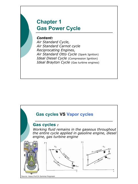
<strong>Chapter</strong> 1<br />
<strong>Gas</strong> <strong>Power</strong> <strong>Cycle</strong><br />
Content:<br />
Air Standard <strong>Cycle</strong>,<br />
Air Standard Carnot cycle<br />
Reciprocating Engines,<br />
Air Standard Otto <strong>Cycle</strong> (Spark Ignition)<br />
Ideal Diesel <strong>Cycle</strong> (Compression Ignition)<br />
Ideal Brayton <strong>Cycle</strong> (<strong>Gas</strong> turbine engines)<br />
<strong>Gas</strong> cycles VS Vapor cycles<br />
<strong>Gas</strong> cycles :<br />
Working fluid remains in the gaseous throughout<br />
the entire cycle applied in gasoline engine, diesel<br />
engine, gas turbine engine<br />
Source: Assoc.Prof.Dr.Sommai Prepream
<strong>Gas</strong> cycles VS Vapor cycles (cont’d)<br />
Vapor cycles :<br />
Working fluid exists in the vapor phase during<br />
on part of the cycle and in the liquid phase<br />
during another part such as in steam power<br />
plant cycle and refrigeration cycles<br />
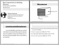
The Carnot <strong>Cycle</strong> and Its Value in Engineering<br />
Heat<br />
Engine<br />
Source, T H<br />
Sink, T L<br />
Q H<br />
Q L<br />
W net<br />
The 4 processes of the carnot cycle: (Heat Engine)<br />
� Reversible Isothermal heat transfer from high temp.<br />
reservoir.<br />
� Reversible adiabatic expansion.<br />
� Reversible Isothermal heat transfer to low temp. reservoir<br />
� Reversible adiabatic compression
Example 8.1 Show that the thermal efficiency of a Carnot<br />
cycle operating between the temperature limits of T L AND<br />
T H is solely a function of these two temperatures.<br />
Solution<br />
from<br />
Wnet<br />
QL<br />
ηth<br />
= = 1−<br />
QH<br />
QH<br />
TH 1<br />
2⎛<br />
δQ<br />
⎞<br />
and S2<br />
− S1<br />
= ∫ ⎜ ⎟<br />
1 ⎝ T ⎠rev<br />
for rev. Isothermal process, T = const.<br />
TL 4<br />
1 2<br />
1Q2<br />
then S2<br />
− S1<br />
= Q<br />
T ∫ δ =<br />
1 rev T<br />
or<br />
1Q2<br />
= T ( S2<br />
− S1)<br />
Therefore,<br />
QH<br />
= TH<br />
( S2<br />
− S1),<br />
and QL<br />
= TL<br />
( S3<br />
− S4<br />
)<br />
But S1<br />
= S4,<br />
and S2<br />
= S3<br />
QL<br />
TL<br />
( S3<br />
− S4<br />
) TL<br />
ηth<br />
= 1−<br />
= 1−<br />
= 1−<br />
Q T ( S − S ) T<br />
H<br />
H<br />
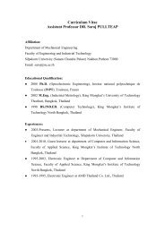
Actual <strong>Gas</strong> <strong>Cycle</strong><br />
2<br />
1<br />
H<br />
T<br />
Q H<br />
Q L<br />
s 1 =s 4 s2 =s 3<br />
� Open <strong>Cycle</strong> (intake, discharge)<br />
� Working fluid is not a pure<br />
substance<br />
� Heat input by COMBUSTION of<br />
a fuel<br />
� Involve friction<br />
Source: Assoc.Prof.Dr.Sommai Prepream<br />
Exhaust<br />
gas<br />
2<br />
3<br />
s<br />
Fuel + air<br />
mixture
Intake<br />
valve<br />
Bore<br />
Air-Standard Assumption<br />
� The working fluid is air which continuously<br />
circulated in a close loop and behave as an<br />
ideal gas<br />
� All the processes are internally reversible<br />
� The combustion process is replaced by a<br />
heated-addition process from the external<br />
source<br />
� The exhaust process is replaced by a heat<br />
rejection process which restores the<br />
working fluid to its initial state<br />
Over View on Reciprocating Engines<br />
Exhaust<br />
valve<br />
Stroke<br />
TDC<br />
BDC<br />
Top Dead Center (TDC) : Position of the piston<br />
when it forms the smallest volume in diameter<br />
Bottom Dead Center (BDC) : Position of the<br />
piston when it forms the largest volume in diameter<br />
Stroke : Length of piston travel<br />
Bore : Diameter of the cylinder<br />
Clearance Volume (Vc ) : minimum volume<br />
formed in the cylinder when the piston is at TDC<br />
Displacement Volume (Vd ) :Swept Volume (Vmax-Vmin )<br />
Source: Assoc.Prof.Dr.Sommai Prepream<br />
Compression Ratio (r v ) = (V max /V min ) = (V BDC /V TDC )<br />
Mean Effective Pressure (MEP) : Fictious pressure that acted on the<br />
piston during the entire power stoke<br />
Net Work during the actual cycle (Wnet ):<br />
Wnet = (MEP) x (Piston Area) x (Stroke) = (MEP) x (Displacement Volume)
P<br />
Mean Effective Pressure, MEP Concept<br />
Actual Processes<br />
v min<br />
W net<br />
Equivalent<br />
v max<br />
TDC BDC<br />
Source: Assoc.Prof.Dr.Sommai Prepream<br />
Four Stroke Engine<br />
v<br />
P<br />
MEP<br />
Equivalent by MEP<br />
v min<br />
W net<br />
v max<br />
Wnet = (MEP) x (Displacement Volume)<br />
= (MEP) x (Vmax-Vmin )<br />
Intake Compression <strong>Power</strong> Exhaust<br />
1. Intake Stroke piston moves from TDC to BDC,<br />
drawing in fresh air-fuel mixture.<br />
2. Compression Stroke piston moves from BDC to<br />
TDC, compress air-fuel mixture.<br />
3. <strong>Power</strong> Stroke piston at TDC, spark plug ignite<br />
the air-fuel mixture. the combustion occur<br />
very fast that, in theory, the piston still at<br />
TDC. After that the piston is pushed to BDC.<br />
4. Exhaust Stroke piston moves from BDC to TDC,<br />
pushes the combustion gases out.<br />
v
Two Stroke Engine <strong>Power</strong><br />
Compression<br />
Intake &<br />
Exhaust<br />
1. Compression Stroke piston moves from<br />
BDC to TDC, compress air-fuel<br />
mixture.<br />
2. <strong>Power</strong> Stroke piston at TDC, spark plug<br />
ignite the air-fuel mixture. After the<br />
piston is pushed to BDC. Meanwhile,<br />
about half way, combustion gases are<br />
discharged and fresh air-fuel mixture<br />
is drawing in .<br />
Actual and Ideal cycles in spark-ignition engine<br />
Actual four-stoke spark-ignition<br />
engine<br />
Ideal Otto<br />
cycle<br />
Under the Air-Standard Assumption
P<br />
Air Standard Otto <strong>Cycle</strong><br />
Ideal Otto cycle consists of four internally reversible processes:<br />
Process 1-2 Isentropic Compression<br />
Process 2-3 v = constant, heat added<br />
Process 3-4 Isentropic expansion<br />
Process 4-1 v = constant, heat rejection<br />
3<br />
2<br />
v 2 =v 3<br />
Pv k = c<br />
Pv k = c<br />
w in<br />
w out<br />
1<br />
v 1 =v 4<br />
TDC BDC<br />
Source: Assoc.Prof.Dr.Sommai Prepream<br />
4<br />
v<br />
T<br />
1<br />
2<br />
v = const.<br />
v = const.<br />
q in<br />
q out<br />
s 1 =s 2 s3 =s 4<br />
There are only 2-stroke of all 4-processes,<br />
Analysis of Air Standard Otto <strong>Cycle</strong><br />
Constant volumeheat<br />
transfer<br />
1<br />
st<br />
v = const.<br />
⇒ w = 0<br />
Idealgas:<br />
and<br />
IsentropicProcessof<br />
Idealgases<br />
and<br />
law : closedsystem<br />
2<br />
2<br />
2<br />
q<br />
in<br />
3<br />
out<br />
k<br />
3<br />
= u − u + w<br />
3<br />
=<br />
2<br />
4<br />
3<br />
3<br />
1<br />
= P<br />
3<br />
k<br />
1v1<br />
2<br />
2<br />
q = u − u<br />
Pv<br />
q<br />
Pv<br />
RT, du<br />
= q = C (T −T<br />
)<br />
k<br />
v<br />
v<br />
3<br />
= P<br />
2<br />
=<br />
q = q = C (T −T<br />
)<br />
1<br />
3<br />
k<br />
2v2<br />
C dT<br />
P ⎛ 2 v ⎞ ⎛ 1 V ⎞ 1<br />
= ⎜<br />
⎟ = ⎜<br />
⎟<br />
P1<br />
⎝ v2<br />
⎠ ⎝V2<br />
⎠<br />
( k−1)<br />
/ k<br />
T ⎛ ⎞ ⎛ ⎞<br />
2 P2<br />
v1<br />
= ⎜<br />
⎟ = ⎜<br />
⎟<br />
T1<br />
⎝ P1<br />
⎠ ⎝ v2<br />
⎠<br />
2<br />
4<br />
= constant<br />
k<br />
v<br />
k −1<br />
P<br />
T<br />
3<br />
2<br />
v 2 =v 3<br />
1<br />
Pv k = c<br />
2<br />
s 1 =s 2<br />
3<br />
4<br />
Pv k = c<br />
v = const.<br />
v =<br />
const.<br />
w in<br />
q in<br />
q out<br />
s<br />
w out<br />
4<br />
1<br />
v 1 =v 4<br />
3<br />
4<br />
s3 =s 4<br />
v<br />
s
Analysis of Air Standard Otto <strong>Cycle</strong> (cont’d)<br />
Thermal efficiency<br />
w<br />
η th =<br />
q<br />
w<br />
1<br />
2<br />
3<br />
C<br />
= c,<br />
k =<br />
C<br />
P2v<br />
2 − P1v<br />
1<br />
1w<br />
2 =<br />
1−<br />
k<br />
R(<br />
T2<br />
− T1<br />
)<br />
1w<br />
2 =<br />
1−<br />
k<br />
qL<br />
4 q<br />
or,<br />
η th = 1−<br />
= 1−<br />
q q<br />
Mean Effective Pressure<br />
w<br />
net<br />
w =<br />
Pv<br />
k<br />
net<br />
= w + w<br />
∫<br />
net<br />
in<br />
Pdv<br />
= MEP ( v − v )<br />
4<br />
H<br />
1<br />
p<br />
v<br />
2<br />
2<br />
1<br />
3<br />
P<br />
T<br />
3<br />
2<br />
v 2 =v 3<br />
1<br />
Pv k = c<br />
2<br />
s 1 =s 2<br />
Pv k = c<br />
v = const.<br />
v =<br />
const.<br />
Spark-ignition Engine<br />
1. The higher r v the higher thermal eff.<br />
2. The higher r v cause Self-Ignition � engine knock<br />
3. Higher Octane Number of fuel used retard the self-ignition<br />
4. Typical r v of gasoline engine ~ 9.0 – 10.0<br />
5. Thermal efficiency of actual spark ignition engine ~ 25-30%<br />
v<br />
w in<br />
q in<br />
q out<br />
w out<br />
4<br />
1<br />
v 1 =v 4<br />
3<br />
4<br />
s3 =s 4<br />
v<br />
v<br />
s
Example 8.2 An ideal Otto cycle has a compression ratio of 8. At the<br />
begining of the compression process, the air is at 100 kPa and 17 o C,<br />
and 800 kJ/kg of heat is transfered to air during the heat addition<br />
proceed. Accounting for the variation of specific heats of air with<br />
temperature, determine, (a) the maximum temperature and pressure<br />
which occur during the cycle, (b) the net work out put, (c) the thermal<br />
efficiency, and (d) the mean effective pressure of the cycle<br />
Given:<br />
rv = 8.0<br />
P1 = 100 kPa and<br />
T1 =17oC qH = 800 kJ/kg<br />
variation of specific<br />
heats<br />
Determine:<br />
a) T max<br />
b) w net<br />
c) η th<br />
d) MEP<br />
P<br />
3<br />
2<br />
v 2 =v 3<br />
Pv k = c<br />
Pv k = c<br />
4<br />
1<br />
v 1 =v 4<br />
v<br />
T<br />
1<br />
2<br />
s 1 =s 2<br />
v = const.<br />
v = const.<br />
(a) T max = T 3 :find state 2 and then 3 using Ideal gas eqn.<br />
and Table A-17<br />
Table A-17 ; T 1 = 290 K � u 1 = 206.91 kJ/kg, and v r = 676.1<br />
w in<br />
1-2 Isentropic proc. v r2/v r1 = v 2/v 1 , v 2/v 1 =1/r v = 1/8,<br />
� v r2 = v r1/r v = 676.1/8.0 = 84.51<br />
Table A-17 : at v r2 = 84.51 � T 2 = 652.4 K and u 2 = 475.11 kJ/kg,<br />
P 2v 2 /T 2 = P 1v 1/T 1 ,<br />
P 2 = P 1(v 1/v 2 )(T 2/T 1 ) = (100 kPa)(8.0)(652.4/290) = 1799.7 kPa<br />
2-3 Constant volume heat added,<br />
1 st law q 23 = w 23 + u 3 –u 2 ; w 23 = 0<br />
q 23 = u 3 –u 2 ; 800 kJ/kg = u 3 – 475.11<br />
� u 3 =1275.11 kJ/kg � table A-17: T 3 = 1575.1 K and v r3 = 6.108<br />
P 3v 3/T 3 = P 2v 2 /T 2 ,<br />
P 3 = P 2(v 2/v 3 )(T 3/T 2 ) = (1799.7 kPa)(1/8.0)(1575.1/652.4) = 543.4 kPa<br />
T max =T 3 = 1575.1 K answer<br />
w out<br />
q in<br />
q out<br />
3<br />
4<br />
s3 =s 4<br />
s
(b) w net = q H –q L , similar to q 23 ; -q L =q 41 = u 1 –u 4<br />
3-4 Isentropic proc.<br />
v r4/v r3 = v 4/v 3 , v 4/v 3 =r v = 8, � v r4 = v r3r v = 6.108*8.0 = 48.864<br />
Table A-17 : at v r4 = 48.864 � T 2 = 795.6 K and u 4 =588.74 kJ/kg,<br />
4-1 Constant volume heat rejected,<br />
1 st law q 41 = w 41 + u 1 –u 4 ; w 41 = 0<br />
q 41 = u 1 –u 4 = 206.91 - 588.74 = -381.83 kJ/kg<br />
q L = -q 41 = 381.83 kJ/kg<br />
w net = q H –q L = 800 – 381.83 = 418.17 kJ/kg answer<br />
(c) η th = w net /q H = 418.83/800 = 0.523 or 52.3 % answer<br />
(d) MEP = w net /(v 1-v 2 ) ; P 1v 1 = RT 1<br />
� v 1 = 0.832 m 3 /kg , v 2 =v 1/8,<br />
MEP = 574.4 kPa answer<br />
Spark-ignition Engine<br />
Diesel cycles: the ideal cycle for<br />
compression-ignition engine<br />
Ideal diesel cycle consists of four internally reversible processes:<br />
Process 1-2 Isentropic Compression<br />
Process 2-3 P = constant, heat added<br />
Process 3-4 Isentropic expansion<br />
Process 4-1 v = constant, heat rejection<br />
P<br />
2<br />
q in<br />
v 2 =v 3<br />
3<br />
Pv k = c<br />
Pv k = c<br />
4<br />
1<br />
v 1 =v 4<br />
q out<br />
v<br />
T<br />
1<br />
2<br />
P = const.<br />
v = const.<br />
q in<br />
q out<br />
s 1 =s 2 s3 =s 4<br />
4<br />
3<br />
s
1st law : closed system<br />
Ideal gas:<br />
and<br />
Analysis of Ideal Diesel <strong>Cycle</strong><br />
Constant pressure heat transfer<br />
2<br />
P = const.<br />
⇒ w = P ( v − v )<br />
and<br />
2<br />
2<br />
4 1<br />
3<br />
3<br />
3<br />
2<br />
= − q = C ( T −T<br />
)<br />
Isentropic Process of Ideal gases<br />
3<br />
1<br />
4<br />
3<br />
2<br />
3<br />
1<br />
k<br />
1v1<br />
4<br />
3<br />
Pv = RT, dh = C dT<br />
q = q = C (T −T<br />
)<br />
in<br />
2<br />
2<br />
q = u − u = −C<br />
( T −T<br />
)<br />
q<br />
q = u − u + w<br />
out<br />
k<br />
Pv = P<br />
k<br />
p<br />
3<br />
v<br />
= P<br />
2<br />
2<br />
4<br />
2<br />
k<br />
2v2<br />
P ⎛ 2 v ⎞ ⎛ 1 V ⎞ 1<br />
= ⎜<br />
⎟ = ⎜<br />
⎟<br />
P1<br />
⎝ v2<br />
⎠ ⎝V2<br />
⎠<br />
( k −1)<br />
/ k<br />
T ⎛ ⎞ ⎛ ⎞<br />
2 P2<br />
v1<br />
= ⎜<br />
⎟ = ⎜<br />
⎟<br />
T1<br />
⎝ P1<br />
⎠ ⎝ v2<br />
⎠<br />
3<br />
q = u − u + P ( v − v ) = h − h<br />
v<br />
2<br />
3<br />
4<br />
1<br />
= constant<br />
k<br />
p<br />
k −1<br />
2<br />
1<br />
3<br />
2<br />
P<br />
T<br />
2<br />
q in<br />
v 2 =v 3<br />
2<br />
1<br />
s 1 =s 2<br />
3<br />
Pv k = c<br />
P = const.<br />
Pv k = c<br />
q in<br />
v = const.<br />
Analysis of Ideal Diesel <strong>Cycle</strong><br />
Cut off ratio (r c ) is the ratio of the cylinder<br />
volume after and before the combustion process<br />
Thermal<br />
w<br />
η th =<br />
q<br />
from<br />
at<br />
net<br />
H<br />
r c<br />
efficiency<br />
q<br />
= 1 −<br />
q<br />
V3<br />
v3<br />
= =<br />
V v<br />
T1<br />
( T4<br />
/ T1<br />
− 1)<br />
= 1 −<br />
kT ( T / T − 1)<br />
2<br />
definition<br />
processes<br />
3<br />
out<br />
in<br />
of<br />
2<br />
2<br />
1 − 2 and 3 − 4<br />
2<br />
T4<br />
− T1<br />
= 1 −<br />
k ( T − T )<br />
r<br />
c<br />
and<br />
k<br />
1 ⎡ r ⎤<br />
c − 1<br />
η th = 1 − k −1<br />
⎢ ⎥<br />
r ⎣ k ( rc<br />
− 1)<br />
⎦<br />
3<br />
2<br />
isentropic<br />
P<br />
T<br />
2<br />
q in<br />
v 2 =v 3<br />
2<br />
3<br />
Pv k = c<br />
1<br />
s 1 =s 2<br />
Pv k = c<br />
P = const.<br />
q in<br />
v = const.<br />
q out<br />
4<br />
1<br />
v 1 =v 4<br />
q out<br />
4<br />
1<br />
v 1 =v 4<br />
4<br />
3<br />
s3 =s 4<br />
q out<br />
v<br />
4<br />
3<br />
s3 =s 4<br />
q out<br />
v<br />
s<br />
s
Compression Ignition Engine<br />
1. The thermal efficiency of Diesel cycle always higher than Otto cycle<br />
( η th , diesel > ηth,<br />
otto ).<br />
2. The diesel engines operated at the higher rv and burn the fuel more<br />
completely.<br />
3. Typical rv of diesel engine ~ 12.0 – 23.0<br />
4. In a gasoline engine, it’s air intake is carefully restricted and controlled by<br />
the carburetor for a 15:1 air to fuel ratio. However, in the diesel engine,<br />
the air intake is unrestricted.<br />
5. Thermal efficiency of actual diesel engine ~ 35-40%.<br />
Compressor<br />
Typical<br />
compression<br />
ratios for<br />
diesel<br />
engines<br />
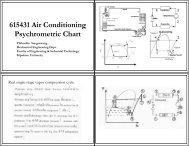
Brayton <strong>Cycle</strong>: The Ideal <strong>Cycle</strong> for<br />
<strong>Gas</strong>-turbine Engines<br />
Combustion Chamber<br />
Turbine<br />
An open-cycle gas turbine engine<br />
Win<br />
v<br />
qin<br />
Heat Exchanger<br />
Compressor Turbine<br />
Heat Exchanger<br />
qout<br />
Wout<br />
An closed-cycle gas turbine engine
Ideal Brayton <strong>Cycle</strong><br />
Brayton <strong>Cycle</strong> consists of four internally reversible processes:<br />
Process 1-2 Isentropic Compression (in a compressor)<br />
Process 2-3 P = constant, heat added<br />
Process 3-4 Isentropic expansion (in a turbine)<br />
Process 4-1 P = constant, heat rejection<br />
qin<br />
T<br />
W Wout<br />
s<br />
in<br />
= const.<br />
22<br />
4<br />
2<br />
3<br />
2<br />
4<br />
3<br />
qout<br />
P = const. at process 2 -3<br />
and 4 -1<br />
and P = P and P = P<br />
1<br />
qin<br />
P = const.<br />
P = const.<br />
qout<br />
3<br />
s 1 =s 2 s3 =s 4<br />
Analysis of Ideal Brayton <strong>Cycle</strong><br />
The energy balance for a steady - flow process for Brayton cycle<br />
and<br />
( q − q ) + ( w − w ) = h<br />
in<br />
q = q = h − h = C (T −T<br />
)<br />
q<br />
in<br />
out<br />
out<br />
1<br />
3<br />
4<br />
2<br />
= q = h − h = C (T −T<br />
)<br />
1<br />
Isentropic Process of Ideal gases at process1<br />
- 2 and 3-<br />
4<br />
net<br />
H<br />
k<br />
Pv = P<br />
in<br />
out<br />
p<br />
p<br />
exit<br />
3<br />
− h<br />
4<br />
inlet<br />
2<br />
1<br />
4 1<br />
k k<br />
1v1<br />
= P2v<br />
2 = constant<br />
1<br />
qout<br />
( k −1) / k<br />
⎞ 2<br />
( k −1)<br />
/ k<br />
⎛ P ⎞ 3 T3<br />
s 1 =s 2<br />
s3 s3 =s 4 s<br />
and<br />
T ⎛ 2 P<br />
=<br />
T ⎜<br />
1 P ⎟<br />
⎝ 1 ⎠<br />
= ⎜<br />
P ⎟<br />
⎝ 4 ⎠<br />
=<br />
T4<br />
Thermal efficiency<br />
w<br />
η th =<br />
q<br />
qout<br />
= 1 −<br />
q<br />
T4<br />
− T1<br />
T1<br />
( T4<br />
/ T1<br />
− 1)<br />
= 1 −<br />
= 1 −<br />
k ( T − T ) kT ( T / T − 1)<br />
Pressure<br />
P2<br />
ratio ( rp<br />
) = ; Then<br />
P1<br />
η th = 1 −<br />
r<br />
1<br />
in<br />
from isentropic at processes 1 − 2 and 3 − 4 and<br />
k −1/<br />
k<br />
p<br />
3<br />
2<br />
2<br />
3<br />
2<br />
s<br />
T<br />
P<br />
2<br />
2<br />
qin<br />
qin<br />
P = const.<br />
P = const.<br />
qin<br />
3<br />
s = const.<br />
qout<br />
3<br />
1 4<br />
qout<br />
4<br />
v
<strong>Gas</strong> Turbine Engine<br />
1. The thermal efficiency of an ideal Brayton cycle depends on the<br />
pressure ratio and k.<br />
2. In commom designs, the pressure ratio should be in range of 11-16,<br />
however, it can work in the range at r p= 5 – 20.<br />
3. At the fixed turbine inlet temp. (T 3), the net work output increase with<br />
the pressure ratio, reaches a maximum, and then starts to decrease.<br />
4. <strong>Cycle</strong> efficiency can be improved through increasing the tutbine inlet<br />
temp., increasing the efficiency of turbomachinery components,<br />
modification of the basic cycle.