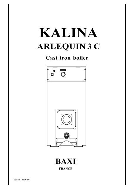
KALINA ARLEQUIN 3 C Cast iron boiler - klimatika
KALINA ARLEQUIN 3 C Cast iron boiler - klimatika
KALINA ARLEQUIN 3 C Cast iron boiler - klimatika
- No tags were found...
Create successful ePaper yourself
Turn your PDF publications into a flip-book with our unique Google optimized e-Paper software.
<strong>KALINA</strong><strong>ARLEQUIN</strong> 3 C<strong>Cast</strong> <strong>iron</strong> <strong>boiler</strong>BAXIFRANCEEdition : 0306-001
PageI. GENERAL REMARKS ...................................................................................... 3Designation ...................................................................................................................................... 3Guarantee ......................................................................................................................................... 3II. TECHNICAL CHARACTERISTICS ............................................................... 4Dimensions ...................................................................................................................................... 4Gassideresisitanceandrequireddraught .......................................................................................... 4III. ASSEMBLING THE BOILER .......................................................................... 5IV. INSTALLATION................................................................................................. 7Hydraulicdiagram ............................................................................................................................. 7Installation ....................................................................................................................................... 7Draughtregulator ............................................................................................................................. 7Connectiontotheflue ....................................................................................................................... 7V. ELECTRICAL DIAGRAM ................................................................................ 8VI. PUTTING INTO SERVICE ............................................................................... 8VII. USE - IGNITION ................................................................................................. 8VIII. MAINTENANCE ................................................................................................ 9IX. SPARE PARTS.................................................................................................. 102
IGENERALREMARKSHeat generator for hot water centralheating.May be used to supply water radiators orconvectors.Designed for fitting in new and existingaccommodation.Particularly recommendedfor replacingdilapidated<strong>boiler</strong>s.- 6models- <strong>Cast</strong>-<strong>iron</strong>heatingbody,assembledelements, with cleaning front plate.- Lined inwhite lacqueredsheet steel- Reinforced thermal insulation thickness 50mm- Pre-wired control panel- Mainswitch- Thermostat to regulate the temperature ofthe heating water- Boiler thermometer- Safety limit with manual resetDesignation :<strong>KALINA</strong><strong>ARLEQUIN</strong>3CGuarantee:The guarantee does not cover:- scaleformation or its consequences- accidents due to frost- damage to the exterior and interior finish- damage caused byhigh pressure in theheating circuit- accidents due to faulty operation of thecontrol or safety gear- defects in the electrical installation:connections, voltage, etc.- abnormal wear and tear- indemnities for the cost of labour,downtime, transport, etc.Type kW kWCE92/42 CXArlequin3C28 28 31Arlequin3C 36 36 39Arlequin3C44 44 48Arlequin3C52 52 56,5Arlequin3C60 60 65Arlequin3C70 67 743
II-TECHNICALCHARACTERISTICSKalina <strong>ARLEQUIN</strong> 3CModel : N° 28 36 44 52 60 70Water contents (litre) 14,5 17,7 20,9 24,1 27,3 30,5Ø Flow / return heating 1"1/4 1"1/4 1"1/4 1"1/4 1"1/4 1"1/4Position of flow heating axis in relation to the floor , mm 683 683 683 683 683 683Ø smoke flow, mm 130 / 125 130 / 125 130 / 125 150 150 150Position of smoke flow axis in relation to the floor, mm 558 558 558 558 558 558Number of intermediate sections 2 3 4 5 6 7Height 920 920 920 920 920 920Width 445 445 445 445 445 445Depth (TD) 580 580 746 746 912 912Depth (D) 500 500 666 666 832 832Recommended burners TIGRA CF 700 CF 700 CF 700 CF 700 CF 900 CF 90028 36 44 52 60 70CE 92/42 CE 92/42 CE 92 /4 2 CE 92/42 CE 92/42 CE 92 /42Required draught (mbar) 0,06 0,09 0,1 0,16 0,24 0,31Gas side resistance and combustionchamber pressure (mbar) 0,03 0,04 0,07 0,11 0,19 0,26T° flue - room t° 204 204 204 204 204 204Exit flue gas mass flow (kg/h) 47,9 61,5 74,9 88,5 102 115,3Nominal power (kW) 27,8 35,7 43,5 51,4 59,2 67Max. heat input (kW) 30,7 39,3 47,8 56,4 65 73,6Furnace vol. (dm³) 10,22 15,33 20,44 25,55 30,66 35,77Boiler smoke circuit volume (dm³) 14,88 21,87 28,86 35,85 42,84 49,83Load loss water side (mbar) 0,9 1,35 2,45 3,9 5,7 7,7Maintenance consumption coefficient (%) 0,56 0,49 0,42 0,35 0,28 0,21Dimensions Kalina <strong>ARLEQUIN</strong> 3CD920750558683313DD+45.2T D20133FRONT VIEW LEFTSIDE VIEWREAR VIEW4
III- ASSEMBLINGTHEBOILERA. Placement of the cast <strong>iron</strong> block :A stand should be constructed in compliance with the regulations and taking into account the dimensions and the weight of the <strong>boiler</strong>.Position the cast <strong>iron</strong> block by taking into account the dimensions of the casing.B. Hydraulic connection of the heating block to the installation :- Connect the flow circuit and return to the 5/4" tappings.- Connect the drain cock to the 1/2" tapping on the lower part of the front element of furnace.Important : take into account the totalspace of the casing by making thehydraulic connection of the <strong>boiler</strong> to theheating circuit.C. Fixing the back support of the casing (1):Back supportofcasing (1)GrommetFor this, place the back support of the casingon the upper braces using the two M12DIN 934 screwssupplied withthe screw-kit.Fix the two grommets on to the back supportD.Fixing the insulation:1. Place the insulation around the heatingbody, joining the insulation mat below the heating body.2. Bind it with the tapes but do not tighten tomuch (to obtain optimal insulation).3. Place the pre-cut insulation on the back side (hydraulicconnection and connection with the chimney)4. Hold in place with the tapes.Adapt smoke pipe length according to<strong>boiler</strong>dimension.PipeFor optimal insulation do not overtighten.E. Coupling of the furnace to the flue :250min.500max.- Provide a 150 or 130/125 mm smoke pipe- Height from socket to axis of smoke pipe : 558 mm- Place the flue collar- Ensure the air tightness of the coupling250min.BoilerImportant :Before installing the <strong>boiler</strong>, foresee enough space behindit to enable the placing of the rear panels.Burner5
F. Placing of side panels :- Fix the support of the casing(1) with 2 nuts M12 DIN 934 (see detailE)- Fix 1 protection of cable Ø 24 (see detail E)- Fix the support of the casing(2) with 2 screws M8-12 (see detailC)- Fix side panel (3-4) with each time 2 screws M8-12 (see detailsD)G. Placing of control panel:- Fasten the control panel (5) on side panels with 4 black screws DIN 7981C 4.2 - 9.5 (see detailB).- Place the <strong>boiler</strong>'s thermostats bulbs (control and safety limit)and the thermometer bulb in the feeler sleeve providedfor this purpose in the rear element.H. Placing of cover- After having made the electrical connections, place the cover(6) with 2 Parker screws DIN7981 4.2 - 10 (see detailA).- Fix 1 protection of cable Ø 24 (see detail A)I. Placing of front panel block- After fixing the 4 screws DIN 7981 C 4.2 - 9.5 on the side panels (see detail D and F)- Place the front panel (7)J. Placing of rear panels- Fix the 8 Parker screws DIN 7981 C 4.2 - 9.5 (black) to maintain the rear upper panel.6ADETAIL EECHELLE 1:3DÉTAIECHELLE L E 1 :3DETAIL CECHELLE 1:3DÉTAIECHELLE L F 1 :2F31EDETAIL DÉTAI AECHELLE L A 1 :ECHELLE 3 1:35B724DETAIL DECHELLE 1:3ECHELLEDÉTAIL D 1 :3DETAIL DÉTAI BECHELLE L B 1 :ECHELLE 2 1:3CDDETAIL FECHELLE 1:3DÉTAIECHELLE L C 1 :36
IV-INSTALLATIONHYDRAULICDIAGRAMRadiatorsSafety valveBoilerExpansiontankIsolation valveDifferentialpressure valve (*)Isolation valveCirculationpumpheating circuitFillingvalve* In the case where all the radiators of the installation are provided with thermostat valves,provide a differential pressure valvebetween the <strong>boiler</strong> outflow and return- InstallationThese <strong>boiler</strong>s are designed to be installed in a <strong>boiler</strong> room or in a service annex.It is necessary to check the ventilation of such a place.If the height of the flue is less than 6 m, provide a basic ventilation of 1.5 dm² per 17.5 kW.If the height of the flue is more than 6 m, provide a basic ventilation of 1 dm² per 17.5 kW.The <strong>boiler</strong> room must be in accordance with the regulations in force.- Draught RegulatorIt is necessary to provide, on the body of the flue, approximately 50 cm above the line of the connecting pipe, a draught regulator of adiameter equivalent to that of the flue, which will be regulated according to the pressure losses of the <strong>boiler</strong>.On stopping the burner, the valve will be held slightly open in order to ventilate the flue and to eliminate condensation mists.- Connection to the flueBefore installing a piece of apparatus, we strongly advise that the installer checks the flue (soot deposits, air inlet interference, cracks, etc.)in order to be sure that it is in a good condition. The efficiency of this <strong>boiler</strong> leads to relatively low fume temperatures. Special care mustbe paid to the flue, which must be heat-insulated and leak-proof. In fact a lack of leak-proof quality and bad insulation of the flue will lowerthe temperature of fumes, causing staining. One of the provisions to be made is to line the tubes. The quality of lining must be compatiblewith thefuel used.7
V-ELECTRICALDIAGRAMBurnerB4S3T2T1NL1L N L N L L°C1 2 3 4 5 6230 V - 50 HzNL1 2PCirculation pump(not supplied)Remotethermostat(not supplied)230 V - 50 Hz - EarthSafety limitwith manualresetSP-051 HEP 1 21 42 5BoilerthermostatNT 174 HE/2Main switchVI-PUTTINGINTOSERVICECOLDFILLINGPRESSUREOFTHEINSTALLATIONBefore filling the installation, adjust thenitrogen pressure of the expansion tankaccording to the height of the installation. Youobtain the value of this nitrogen pressure(P tank[bar]) by dividing the manometric heightof the installation by 10 and adding a marginof 0.2 to 0.5.E.g. For an installation height of 6 m: P tank=(6/10+0.3) = 0.9 barThe pressure with which the water of theinstallation will come to be pushed againstthe diaphragm of the tank must be such thatthe diaphragm is slightly cambered by theaction of the water (P tank+[0.2 to 0.5]). Inthe above example, the cold water fillingpressure of the installation must then beadjustedto approximately:P filling= 0.9 + 0.3 = 1.2 barFilling the <strong>boiler</strong> with water must be complete.Non-observance of thisinstruction willinvalidatethe guarantee.VII-USE-IGNITION- place the <strong>boiler</strong> under pressure by means ofthe general cut-off switch- set the control thermostat to thetemperaturedesired- after bringing the installation up totemperature, again completely bleed of water.ATTENTIONBefore ignition, open the bleed valves, slowlyrefill the installation,and let the air out until the water appears,then close the bleeds.Check for leaks.Check the connection of the smoke flue. Setthe circulator speed according to the pressurelosses of the heating circuit.CONTROLPANEL14231) Mainswitch2) Boiler Thermometer3) Boiler Thermostat4) Safety limit with manual reset (110°C)8
VIII-MAINTENANCEThe user is strongly advised to enter into anannual maintenancecontract withthe installeror a specialist company. In this way, theequipmentand theinstallation willbecheckedandcleaned,theburnerwillbesetcorrectly,andtheunitwillgivefullsatisfaction.Itwilloperatein a most economical manner.Operations to be carried out:- Open the fire-box plate- Have your chimney swept regularly, atleast once each year.- Put a brush in horizontally and brush the flue- Brush the interior of the fire-box and removedeposits and dust from the flapinthesmokepipe and in the fire-box.- Possibility of using chemical cleaners withspray products.- Clean and check the burner, following theinstructions in the technical l e a f l e taccompanyingthe equipment.- Replacetheparts.Checkthoroughlyforleaksin the front plate.FLUEC O M B U S T I O NCHAMBERCleaning the flueHave your flue swept regularly, at least onceeach year. Check for leaks in the smoke pipe.EmptyingEmptying the cylinder and the <strong>boiler</strong> is vital ifthere is any risk of frost. For the <strong>boiler</strong>, use adrainage tap located in its lower section.If you are often away, have anti-freeze put inthe installation.RecommendationCheck the water pressure in the installationregularly.The value indicated on the gauge must not beless than 1 bar cold.Combustion characteristicsAftereachtimetheburneriscleaned,thecombustionregulator is checked with measuringand controlinstruments.It is necessary to ensure that:- the flow of fuel is not greater than that indicated-theflamedoesnotlickthewallsofthecombustionchamber- the temperature of fumes is between 180ºC and220ºC- the CO 2content is from 11 to 13% - the fumeindex is less than 1- the burner has to operate in a proper mannerwithoutpulsation andwithout coughing.ATTENTION!Before any intervention, cut off the current tothe <strong>boiler</strong> by means of the main switch.The overheatingthermostat istriggered: checkwater fill, the operationof thecirculator, andthe regulator thermostat.Awarninglightontheburnerislit:thebreakdownarisesfromtheburner.Waitsomeminutesandreset the control relay located at the front ofthe burner. If nothing happens, call yourinstaller or a specialist company.9
IX-SPAREPARTS<strong>ARLEQUIN</strong> 3C cast-<strong>iron</strong> block101112986712345<strong>ARLEQUIN</strong> 3C casing32373034383531363310
<strong>ARLEQUIN</strong> 3C control panel515350495211
Fig. Quantity Descriptionofthe parts Code1 Kalina<strong>ARLEQUIN</strong>3C28(assembledcast-<strong>iron</strong>block) 0-01-305-400021 Kalina<strong>ARLEQUIN</strong>3C36(assembledcast-<strong>iron</strong>block) 0-01-305-400031 Kalina<strong>ARLEQUIN</strong>3C44(assembledcast-<strong>iron</strong>block) 0-01-305-400041 Kalina<strong>ARLEQUIN</strong>3C52(assembledcast-<strong>iron</strong>block) 0-01-305-400051 Kalina<strong>ARLEQUIN</strong>3C60(assembledcast-<strong>iron</strong>block) 0-01-305-400061 Kalina<strong>ARLEQUIN</strong>3C70(assembledcast-<strong>iron</strong>block) 0-01-305-400071 Kalina<strong>ARLEQUIN</strong>3C28(separatedsections) 0-01-305-403021 Kalina<strong>ARLEQUIN</strong>3C36(separatedsections) 0-01-305-403031 Kalina<strong>ARLEQUIN</strong>3C44(separatedsections) 0-01-305-403041 Kalina<strong>ARLEQUIN</strong>3C52(separatedsections) 0-01-305-403051 Kalina<strong>ARLEQUIN</strong>3C60(separatedsections) 0-01-305-403061 Kalina<strong>ARLEQUIN</strong>3C70(separatedsections) 0-01-305-403071 Kalina <strong>ARLEQUIN</strong>3C28cast-<strong>iron</strong>block+plate 4-01-300-010021 Kalina <strong>ARLEQUIN</strong>3C36cast-<strong>iron</strong>block+plate 4-01-300-010031 Kalina <strong>ARLEQUIN</strong>3C44cast-<strong>iron</strong>block+plate 4-01-300-010041 Kalina <strong>ARLEQUIN</strong>3C52cast-<strong>iron</strong>block+plate 4-01-300-010051 Kalina <strong>ARLEQUIN</strong>3C60cast-<strong>iron</strong>block+plate 4-01-300-010061 Kalina <strong>ARLEQUIN</strong>3C70cast-<strong>iron</strong>block+plate 4-01-300-010071 1 Fuel plate 2-04-020-040002 1 Flame sight plate 2-00-150-300003 1 Burner door insulation 1-30-310-000414 1 Cleaning plate 2-04-020-050005 1 Fuel plate insulation 1-30-300-010006 1 Cleaning plate insulation 1-30-300-010027 1 Front section 2-01-000-000008 3 Intermediate section 2-01-000-020009 1 Insulation of the combustion chamber 1-30-310-0000310 1 Rear section 2-01-000-0100011 1 Plunger 3/4" - 100 + clips 1-70-640-3410112 1 Flue gasboxØ130/125 mmKalina<strong>ARLEQUIN</strong>3C 28to 44 2-04-000-0300012 1 Flue gasbox Ø150 mmKalina <strong>ARLEQUIN</strong>3C52 to 70 2-00-000-03000Kalina<strong>ARLEQUIN</strong>3Ccasing30 1 Lefthand side panel Kalina <strong>ARLEQUIN</strong> 3C 28 & 36 3-01-305-0000330 1 Lefthand side panel Kalina <strong>ARLEQUIN</strong> 3C 44 & 52 3-01-305-0000530 1 Lefthand side panel Kalina <strong>ARLEQUIN</strong> 3C 60 & 70 3-01-305-0000731 1 Righthand side panel Kalina <strong>ARLEQUIN</strong> 3C 28 & 36 3-01-305-0100331 1 Righthand side panel Kalina <strong>ARLEQUIN</strong> 3C 44 & 52 3-01-305-0100531 1 Righthand side panel Kalina <strong>ARLEQUIN</strong> 3C 60 & 70 3-01-305-0100732 1 CoverKalina<strong>ARLEQUIN</strong>3C28&36 3-01-305-0200332 1 CoverKalina<strong>ARLEQUIN</strong>3C44&52 3-01-305-0200532 1 CoverKalina<strong>ARLEQUIN</strong>3C60&70 3-01-305-0200733 1 Rearbottomfixation 3-01-300-0810034 1 Rearupper fixation 3-01-250-0802035 1 Control panel plate 3-01-300-1000036 1 Front panel 3-01-305-0310037 1 Rear upper panel 3-01-250-0502038 1 Rear lower panel 3-00-450-0400049 1 Kalina<strong>ARLEQUIN</strong>3Ccontrolpanel(wired) 5-01-305-1100050 1 Main switch ON / OFF 1-70-380-2012251 1 Boilerthermometer 1-70-880-1012052 1 Boilerthermostat NT174 HE/2 1-70-050-0212053 1 Safetylimit withmanual reset SP-051 HE 1-70-050-0132012


