SR200 Surface Roughness Tester User Manual - Starrett
SR200 Surface Roughness Tester User Manual - Starrett
SR200 Surface Roughness Tester User Manual - Starrett
You also want an ePaper? Increase the reach of your titles
YUMPU automatically turns print PDFs into web optimized ePapers that Google loves.
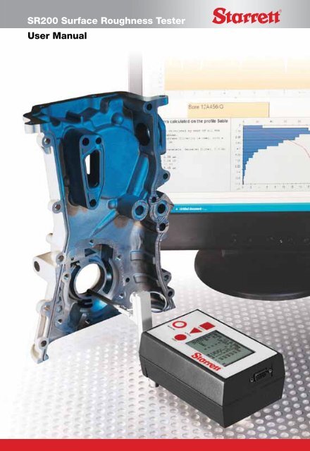
<strong>SR200</strong> <strong>Surface</strong> <strong>Roughness</strong> <strong>Tester</strong><br />
<strong>User</strong> <strong>Manual</strong>
Table Of Contents<br />
Chapter 1 Using the <strong>SR200</strong> with a PC 3.3<br />
Introduction to <strong>Surface</strong> Texture Printing 3.3<br />
terminology and definitions 1.1 To cancel print: 3.3<br />
<strong>Surface</strong> Texture Definitions 1.1 Chapter 4 Menu Settings 4.1<br />
Parameter Definitions 1.2 Main Menu 4.1<br />
Ra 1.2 Cut off 4.1<br />
Rp 1.2 Evaluation length 4.1<br />
RSm 1.2 Parameters 4.1<br />
Rz 1.2 Range: 4.3<br />
Rz1max 1.2 Range Selector Table 4.3<br />
Rt 1.2 Print Settings: 4.3<br />
Rmr 1.3 Units: 4.3<br />
RPc 1.3 Filter: 4.3<br />
Rsk 1.3 Dump Mode: 4.3<br />
Rda 1.3 Dump Mode (Using your <strong>SR200</strong><br />
Chapter 2 Description 2.1 with a PC) 4.3<br />
The Equipment 2.1 SPC Mode 4.4<br />
Traverse Unit 2.2 Language Settings 4.4<br />
Pick-up Mounting Components 2.3 Chapter 5 5.1<br />
Mounting Bracket 2.3 Making Measurements<br />
Adjustable Support 2.4 Technical Considerations 5.1<br />
Pick-up holder 2.4 Operating Notes 5.1<br />
Connector 2.4 On a horizontal surface 5.1<br />
Pick-up 2.5 On other surfaces 5.1<br />
Mounting 2.6 Cut off: 5.2<br />
Chapter 3 Getting Started 3.1 Evaluation Length: 5.2<br />
Battery 3.1 Table of Cut-off values 5.2<br />
Connecting the Pick-up 3.1 Operating Error Indications 5.2<br />
Making a measurement 3.2 Specification 5.3<br />
Switching the <strong>SR200</strong> ON 3.2 RS232 Output 5.3<br />
To cancel a measurement 3.3 Printer Configuration 5.3
Specification for Data Dump 5.5<br />
Chapter 6 Accessories 6.1<br />
Chapter 7 Maintenance 7.1<br />
Calibration 7.1<br />
Reference Standard 7.1<br />
Sensitivity Check and Adjustment 7.1<br />
Cleaning the Stylus 7.1<br />
Pick-up Skid 7.1
Chapter 1<br />
Introduction to <strong>Surface</strong> Texture terminology and definitions<br />
<strong>Surface</strong> Texture Definitions<br />
Every components surface has some form of texture which varies according to its structure<br />
and the way it has been manufactured. These surfaces can be broken down into three main<br />
categories: <strong>Surface</strong> roughness, Waviness and Form. In order to predict a components behaviour<br />
during use or to control the manufacturing process, it is necessary to quantify these surface<br />
characteristics. This is done by using surface texture parameters.<br />
<strong>Surface</strong> Texture Parameters: Can be separated into three basic types: Amplitude, Spacing<br />
and Hybrid.<br />
Amplitude Parameters: Measures of the vertical characteristics of the surface deviations.<br />
Spacing Parameters: Measures of the horizontal characteristics of the surface deviations.<br />
Hybrid Parameters: Combinations of spacing and amplitude parameters.<br />
Mean Line: Is a least squares line of nominal form fitted through the primary profile where<br />
the areas of the profile above and below this line are equal and kept to a minimum separation.<br />
Profile filters as detailed in ISO11562 define the mean lines for the roughness and waviness<br />
profiles.<br />
Cut-off: A cut-off length (or sampling length) is a filter that uses either electronic (2CR)<br />
or mathematical (Gaussian) means to remove or reduce unwanted data in order to look at<br />
wavelengths in the region of interest.<br />
Bandwidth: Is the ratio of the upper Cut-off (Lc) to the lower Cut-off (Ls).<br />
Sample Length: The profile is divided into sample lengths l, which are long enough to include<br />
a statistically reliable amount of data. For roughness and waviness analysis, the sample length<br />
is equal to the selected cut-off (lc) wavelength. The sample length is also known as the cut-off<br />
length.<br />
Evaluation Length: The length in the direction of the X axis used for assessing the profile<br />
under evaluation. The evaluation length may contain one or more sample lengths. For the<br />
primary profiles the evaluation length is equal to the sample length.<br />
1.1 <strong>SR200</strong> Specifications subject to change
Note: almost all parameters are defined over one sample length, however in practice more than one sample<br />
length is assessed (usually five) and the mean calculated. This provides a better statistical estimate of the<br />
parameters measured value.<br />
Parameter Definitions<br />
<strong>Surface</strong> texture is quantified by parameters which relate to certain characteristics of the<br />
texture. The <strong>SR200</strong> offers the following parameters:<br />
Ra, Rp, Rsm, Rz, Rt, Rmr, RPc, Rz1max, Rsk, Rda<br />
Additional parameters can be analysed by downloading results to optional software.<br />
Ra: Universally recognised, and most used, international parameter of roughness. It is the<br />
arithmetic mean of the absolute departures of the roughness profile from the mean line.<br />
Rp: Maximum profile peak height<br />
Mathematically, the largest peak deviation of the roughness profile from the mean line within a<br />
sampling length.<br />
When more than one sampling length is analysed rp is the mean value of the individual rp<br />
values for each sample.<br />
RSm: The mean spacing between profile peaks at the mean line, measured within the<br />
sampling length. (A profile peak is the highest point of the profile between an upwards and<br />
downwards crossing of the mean line).<br />
Rz: Rz = Rp + Rv and is the maximum peak to valley height of the profile within a sampling<br />
length.<br />
When more than one Sampling Length is analysed Rz is the mean value of the individual Rz<br />
values for each Sampling Length.<br />
Rz1max: Maximum Height of Profile<br />
Highest peak to valley within a sampling length. When measured over several sampling lengths<br />
the largest individual sampling length value is taken.<br />
Also known in the past as Rymax, Ry, Rmax or Rti<br />
Rt: Total Height of the Profile.<br />
Maximum Peak to Valley Height of the Profile in the Assessment (evaluation) Length (ln).<br />
<strong>SR200</strong> Specifications subject to change 1.2
Rmr: Material Ratio is the length of bearing surface (expressed as a percentage of the<br />
evaluation length ln) at a depth below the highest peak.<br />
Replaces tp% - Bearing Ratio as defined in ISO 4287 - 1984<br />
RPc: Peak Count<br />
The number of local peaks which project through a selectable band centred about the mean line<br />
or a line parallel to it. The count is determined only over the evaluation length though the results<br />
are given in peaks per cm (or per inch)<br />
Known as Pc before 1997<br />
Rsk: Skewness<br />
Rsk is a measure of the symmetry of the profile about the mean line.<br />
This parameter indicates whether the spikes on the surface are predominately negative or<br />
positive or if the profile has an even distribution of peaks and valleys.<br />
Rda: R Delta a or Rda or RDa - Arithmetical Mean Slope<br />
Arithmetical Mean Slope of the Profile within the Sampling Length.<br />
1.3 <strong>SR200</strong> Specifications subject to change
Chapter 2<br />
Description<br />
The <strong>SR200</strong> is a portable, self-contained instrument for the<br />
measurement of surface texture and is suitable for use in both the workshop and laboratory.<br />
Parameters available for surface texture evaluation are:<br />
Ra, Rz, Rt, Rp, Rmr, RPc, Rv, Rz1max, Rsk, Rda<br />
An explanation of the surface texture parameters evaluated by this instrument is given in<br />
Chapter 1.<br />
The parameter evaluations and other functions of the instrument are microprocessor based.<br />
The measurement results are displayed on an LCD screen and can be output to an optional<br />
printer or computer for further evaluation.<br />
The instrument is normally powered by an alkaline non-recharge-able battery. If preferred, an<br />
optional power adaptor can be used<br />
Figure 1<br />
The Equipment<br />
The standard <strong>SR200</strong> includes:<br />
• 1 Traverse unit<br />
• 1 Standard Pickup<br />
• 1 Reference Specimen<br />
• 1 Pickup cable<br />
• 1 Screwdriver<br />
• 1 Battery<br />
Note: certain items described in this handbook are optional and may not form part of your particular system.<br />
<strong>SR200</strong> Specifications subject to change 2.1
Traverse Unit<br />
The top panel of the traverse unit carries a membrane type control panel and a liquid crystal<br />
display. The unit houses the electronics for controlling the measurement sequence, computing<br />
the mea-<br />
surement data and outputting the results to the display, or to the<br />
RS232 port for use with a printer (when included) or to a com-<br />
puter, for further analysis.<br />
The unit also contains a drive motor which traverses the pickup<br />
across the surface to be measured. The measuring stroke always starts from the extreme<br />
outward position. At the end of the measurement the pickup returns to this position ready for<br />
the next<br />
measurement. The traverse length is determined from selections of cut-off or length.<br />
Figure 2<br />
Pick-up<br />
Connector Select Key Display<br />
Measure key Scroll key Print key<br />
Battery<br />
Battery Compartment<br />
RS232 Connector<br />
2.2 <strong>SR200</strong> Specifications subject to change
Pick-up Mounting Components<br />
The pick-up is fastened to the drive shaft by the following means:<br />
Mounting Bracket. This is clamped to the drive shaft by means of a knurled knob.<br />
Although normally used upright, as shown in figure 3, it can be turned to angle the pick-up or to<br />
take it off the centre line, as shown in figure 3a. It can also be mounted side-ways on the drive<br />
shaft, when the right angle pick-up is in use.<br />
Figure 3: pick up mounting<br />
Pick-up<br />
Insert Extension<br />
rod here Clamp Drive Shaft<br />
Connector Adjustable<br />
Pick-up Support Mounting Bracket<br />
Pick-up Holder<br />
Mounting Bracket<br />
Clamp Screw<br />
Use this mounting position when the right angled pick-up is used<br />
<strong>SR200</strong> Specifications subject to change 2.3
Figure 3a Figure 3b<br />
Adjustable Support: This can be clamped at any position on the slide of the mounting<br />
bracket to provide pick-up height adjustment.<br />
Pick-up holder: This fits into the crutch of the pick-up support and is held in place by a<br />
spring plunger. A biased holder, when used as shown in figure 3, exerts a biasing force on the<br />
pick-up (depending on which way the holder is inserted into the support crutch). It can also be<br />
used to position the pick-up directly underneath the display unit, as shown in figure 4.<br />
Figure 4<br />
The holder will hold the pick-up at right angles to the drive shaft when it is pivoted away from<br />
the surface (eg while changing the work piece).<br />
Connector: The connector of the pick-up lead is screwed into the end of the pick-up and<br />
is then inserted into the end of the pick-up holder, with the lead coming out through the slot<br />
2.4 <strong>SR200</strong> Specifications subject to change
in the holder. It is advisable to connect the lead to the display-traverse unit first and then the<br />
pick-up. To connect the pick-up to the display-traverse unit: the pick-up has 2 threaded ends<br />
with location pins. Insert the location pin securely into the <strong>SR200</strong> body and tighten the threaded<br />
collar.<br />
When the extension rod is used, the short pick-up lead is not required and the end of the rod<br />
itself is inserted into the holder.<br />
Pick-up: The pick-up is a variable inductive type transducer, which is supported on the<br />
surface to be measured by a skid, a curved support projecting from the underside of the pickup<br />
in the vicinity of the stylus. As the pick-up traverses across the surface, movements of the<br />
stylus relative to the skid are detected and con-verted into a proportional electrical signal. The<br />
radius of curvature of the skid is much greater than the roughness spacing. This enables it to<br />
ride across the surface almost unaffected by the roughness, and provide a datum representing<br />
the general form of the surface. Even so, where the waviness is widely spaced it will be<br />
necessary to use the pick-up with shoe, in conjunction with the 2.5mm (0.1in) cut-off.<br />
Figure 5: the pickup is supported on the workpiece by the skid<br />
There are several different types of pickup available designed for different applications, details<br />
are given in the Accessories section of this handbook. They differ only in the stylus tip radius,<br />
the dimensions of the housing or position and the shape of the skid. The stylus material in all<br />
the pickups is diamond for low wear. The skids of the standard pickups are of red ruby.<br />
Figure 6. Standard pick-up dimensions<br />
<strong>SR200</strong> Specifications subject to change 2.5
Mounting: On a flat surface the display-traverse unit can be supported on its three feet.<br />
If a user wishes to make his own mounting bracket for the unit, the dimensions of the fixing<br />
holes are shown in figure 7.<br />
Figure 7<br />
2.6 <strong>SR200</strong> Specifications subject to change
Chapter 3<br />
Getting Started<br />
Battery<br />
To insert a battery, open the compartment by sliding the door to the right and remove the door<br />
from the unit. Insert the battery, with the terminals positioned as shown in the diagram on the<br />
floor of the battery compartment.<br />
Connecting the Pick-up<br />
Plug the lead into the socket on the front of the unit and mount the pick-up as follows: The<br />
connector of the pick-up lead is screwed into the end of the pick-up and is then inserted into<br />
the end of the pick-up holder, with the lead coming out through the slot in the holder. It is<br />
advisable to connect the lead to the display-traverse unit first and then the pick-up. To connect<br />
the pick-up to the dis-play-traverse unit: the pick-up has 2 threaded ends with location pins.<br />
Insert the location pin securely into the <strong>SR200</strong> body and tighten the threaded collar.<br />
Rotate the pick-up to bring the stylus vertical; this can conveniently be done with reference to<br />
the identity number engraved at the end of the pick-up.<br />
Position the Pickup stylus on the component to be measured, with the stylus parallel to the<br />
component (see figure 8 below). Ensure that the stylus tip is in contact with the surface (this<br />
can be verified by checking that the identity number engraved at the end of the pick-up is<br />
vertical). The skid should also be in contact with the surface.<br />
Figure 8<br />
<strong>SR200</strong> Specifications subject to change 3.1
Making a measurement<br />
Note 1: If the pickup has been changed or the instrument is being used for the first time, the instrument<br />
should be calibrated (see Chapter 7).<br />
Note 2: Successful use of the <strong>SR200</strong> will only be possible if it is operated on a surface free from external<br />
vibration - see also operating notes in Chapter 5.<br />
Switching the <strong>SR200</strong> ON<br />
Pressing the SCROLL � key brings the display on and the previously selected set-up is<br />
displayed (provided power has been continuously present). The display is automatically turned<br />
off if the instrument is not used for 30 seconds.<br />
If the battery is dead or has been removed, the previously selected set-up is lost. When a<br />
battery has been replaced and the SCROLL � key is pressed, the start up message will display<br />
for 2 seconds and then the default settings are restored.<br />
The default settings are<br />
Parameter: Ra<br />
Cut-off: 0.8mm<br />
Evaluation length: 4.0mm<br />
Range: 100mm<br />
Data dump evaluation length: 4.0mm<br />
Data dump range: 100mm<br />
No parameter/graph selected for printout<br />
Language English<br />
Filter Gaussian<br />
If the user wishes to change any of these settings, this can be carried out using the SCROLL �<br />
and SELECT � keys (see Chapter 4 for more detail)<br />
Press the MEASURE � key. When the measurement is completed the pickup returns and the<br />
results are displayed on the screen (see example below):<br />
GaussLc 0.80mm<br />
Eval Length 25.0mm<br />
Ra = 0.00µm<br />
Rz = 0.00µm<br />
Rt = 0.00µm<br />
Rp = 0.00µm<br />
RSmm = 0.00µm<br />
more...><br />
3.2 <strong>SR200</strong> Specifications subject to change
If multiple parameters have been selected they may not fit on the display. To continue viewing<br />
the remaining results, click on the SELECT � key.<br />
To cancel a measurement<br />
If Measure is pressed during a traverse, a stop and reversal without measurement will occur<br />
and Measurement Cancelled is displayed.<br />
Using the <strong>SR200</strong> with a PC<br />
If the <strong>SR200</strong> is connected to a PC then measurements will be taken in dump mode, which<br />
is selected using the SCROLL � and SELECT � keys from the main menu (see next<br />
chapter for full set-up details). Position the Pickup stylus on the component to be measured.<br />
Measurements are then activated from the software on the PC. When the measurement is<br />
completed the pickup returns and the results are dumped directly to the PC. During transfer of<br />
the measurement data the message Data Dumping is displayed.<br />
When the data dump is completed, the dump menu still remains active. From the displayed<br />
menu, values of evaluation length and range can be changed and further measurements for<br />
data dump can be made (see next chapter for further details).<br />
Printing<br />
PRINT � key: pressing this key causes the evaluated measurement data to be output to the<br />
RS232 port. When a printer is connected, a printout of all the parameters selected in the print<br />
menu is made.<br />
If SPC has been selected (see chapter 4) the heading is disabled.<br />
Where the profile is longer than 80cm the printout will stop after 80cm. Pressing PRINT key<br />
can print the next 80cm. The printout will start from the beginning of the profile if SELECT is<br />
activated.<br />
If no legal surface data is stored, the error message “Measure before print” is displayed.<br />
To cancel print<br />
Pressing the PRINT � key during printout (before display has updated to Main menu state)<br />
stops the printout and “Printer cancelled” is displayed for 2 seconds. The normal update to<br />
Main-state then continues.<br />
<strong>SR200</strong> Specifications subject to change 3.3
Chapter 4<br />
Menu Settings<br />
The operation of the <strong>SR200</strong> is based on making selections from menus presented on the liquid<br />
crystal display. Two menu states exist, these are: Main Menu and Data Dump Menu. The Data<br />
Dump menu is accessed via the Main Menu and is used when connecting to a PC.<br />
Main Menu<br />
The Main Menu (accessed by pressing the Scrollkey) is used to make the following selections:<br />
CUT-OFF<br />
EVALUATION LENGTH<br />
PARAMETERS<br />
RANGE<br />
PRINT SETTINGS<br />
UNITS<br />
FILTER<br />
DUMP MODE<br />
The SCROLL � key is used to cycle through these options and the SELECT � key is used to<br />
confirm the set up screen required. For a chart of default settings see Chapter 3.<br />
Cut Off:<br />
To select the cut-off required, select the Cut-off option from the main menu. Press the SCROLL<br />
� key to toggle through the cut-off options until the required cut-off is highlighted on the<br />
screen, then press the SELECT � key. See chart in chapter 5 forfurther information.<br />
Evaluation Length.<br />
To select the evaluation length required, select this option from the main menu. Press the<br />
SCROLL � key to toggle through the evaluation length options until the required length is<br />
highlighted on the screen, then press the SELECT � key.<br />
The evaluation length options are determined by the cut-off length selected.<br />
Parameters:<br />
select the Parameters option from the main menu. A list of the parameters available will appear<br />
4.1 <strong>SR200</strong> Specifications subject to change
on the screen (see below). Press the SCROLL � key left to right across the columns then<br />
press the SELECT � key for each parameter required (multiple selections can be made). The<br />
SELECT � key is also used to de-select a parameter.<br />
� Ra RSm<br />
Rz Rz1max<br />
� Rt Rsk<br />
Rmr > > > settings<br />
Rpc > > > settings<br />
Exit<br />
When selecting the Rmr and Rpc parameters, additional settings need to be specified. SCROLL<br />
� onto “Settings” then click on the SELECT � key. The following screen will appear:<br />
Rmr settings<br />
Mr % + Offset<br />
Mean line + Offset<br />
Exit<br />
The SCROLL � key will cycle through ‘Mr% + Offset’, ‘Mean line + Offset’ and ‘Exit’. The<br />
SELECT � key will allow the alteration of one of the 2 settings or, if Exit is highlighted, will<br />
return to the main parameter selection screen.<br />
Pressing SCROLL � will step the cursor (or highlighted character) through the 3 decimal digits<br />
of the percentage, then the sign and 3 decimal digits of the offset and then to OK. Pressing<br />
SELECT � will change the sign/digit - keep pressing SELECT � until the required figure is<br />
reached. Pressing SCROLL � saves the change and moves the cursor along to the next<br />
decimal digit. When complete Select OK to return to the previous menu.<br />
Rmr Settings<br />
Mr% 001%<br />
Offset +00.0µm<br />
OK<br />
The following screen is displayed for Rpc settings and is amended in the same way as above.<br />
Rpc Bandwidth<br />
00.0µm<br />
OK<br />
<strong>SR200</strong> Specifications subject to change 4.2
Range:<br />
Allows the user to scroll through the range options. The most common settings are as follows:<br />
For surfaces
EVALUATION LENGTH<br />
RANGE<br />
UNITS<br />
FILTER<br />
DUMP MODE<br />
All other settings are carried out via the PC.<br />
SPC Mode<br />
If SPC is required, this can be switched on by pressing the PRINT � and SCROLL � key<br />
down simultaneously. The following warning screen will appear:<br />
Warning<br />
Changes to the following settings<br />
are for advanced functions only<br />
Quit OK<br />
Selecting OK displays the Select language and select SPC mode screen. Select the SPC Mode<br />
then SCROLL � will toggle the mode between ON and OFF. When SELECT � is pressed with<br />
OK selected the previous screen will be shown again.<br />
S PC ModeON<br />
OK<br />
Language Settings<br />
The default on the <strong>SR200</strong> is English Language. If the user wishes to select other languages,<br />
press the PRINT � and SCROLL � key down simultaneously. The following warning screen<br />
will appear:<br />
Warning<br />
Changes to the following settings<br />
are for advanced functions only<br />
Quit OK<br />
<strong>SR200</strong> Specifications subject to change 4.4
Selecting OK displays the Select language and select SPC mode screen.<br />
Select Language<br />
Select SPCmode<br />
Quit<br />
SCROLL � down the options and SELECT �<br />
Select Language<br />
English<br />
Français<br />
Deutsch<br />
Italiano<br />
OK<br />
SCROLL � down the list of languages with and SELECT �. This selection will remain as the<br />
default unless power is lost (eg battery is removed).<br />
4.5 <strong>SR200</strong> Specifications subject to change
Chapter 5<br />
Making Measurements - Technical Considerations<br />
Operating Notes<br />
Before measurements are made, there are a few general points of procedure which should be<br />
observed.<br />
1. The surface to be measured must be free from vibration and the instrument must be<br />
completely steady during a measurement.<br />
2. Always turn the pick-up so that the stylus is visibly perpendicular to the surface to be<br />
measured.<br />
3. Set the display-traverse unit so that the traverse is made parallel to the surface being<br />
measured.<br />
4. After a measurement, the traverse unit can be removed from the surface as soon as the<br />
pick-up completes its return stroke. The display will remain visible.<br />
5. Where the texture of a surface has a predominant direc tional character (LAY), it is usual to<br />
traverse across the lay, not along it.<br />
On a horizontal surface<br />
1. Use the biased pick-up holder on the display-traverse unit<br />
2. Clean the surface to be measured, so that it is free from abrasive material, grease, suds etc.<br />
This is necessary to ensure accurate readings and to reduce wear on the skid.<br />
3. Make the cut-off/length and parameter selections required<br />
4. Position the display-traverse unit and pick-up so that the stylus contacts the surface and<br />
the pick-up is approximately parallel to the surface. Make sure that the length of surface is<br />
sufficient for measurement, remembering that the traverse motion is inwards towards the<br />
display-traverse unit.<br />
5. Press the Measure key. When the traverse is completed, the results are displayed and the<br />
pick-up returns to its extreme outward position.<br />
6. If an error message is displayed, identify the cause, correct it and repeat the measurement.<br />
On other surfaces<br />
On a vertical surface:If necessary, hold the display-traverse unit by hand on the surface,<br />
making sure that it does not move during the measurement.<br />
In a small deep bore: Fit the optional extension rod between pickup and holder.<br />
<strong>SR200</strong> Specifications subject to change 5.1
Cut off<br />
A few trial measurements made on different surfaces will soon demonstrate that on some, the<br />
results obtained are very dependent upon the cut-off selected. This shows that it is important<br />
to choose the cut-off to suit the surface. In general, fine surfaces require short cut-offs and<br />
rough surfaces a longer one. The table on the following page gives some guidance on suitable<br />
cut-offs.<br />
Evaluation Length<br />
A long evaluation length is mainly for use on sheet metal and similar materials, where a longer<br />
surface is required to be representatives of the material being examined.<br />
Table of Cut-off values<br />
If not otherwise indicated on a drawing, the following should be used to determine the cut-off<br />
λc (ISO4288)-1996. Recommended Cut-off ISO 4288-1996<br />
Periodic Profiles Non-periodic Profiles Cut-offs<br />
Sampling Length/<br />
Evaluation Length<br />
Spacing Distances<br />
Sm (mm)<br />
Rz(µm) Ra (µm) λc (mm) λc/L (mm)<br />
>0.013 to 0.04 (0.025) to 0.1 (0.006) to 0.02 0.08 0.08/0.4<br />
>0.04 to 0.13 >0.1 to 0.5 >0.02 to 0.1 0.25 0.25/1.25<br />
>0.13 to 0.4<br />
>0.5 to 10 >0.1 to 2 0.8<br />
0.8/4<br />
>0.4 to 1.3<br />
>10 to 50 >2 to 10 2.5<br />
2.5/12.5<br />
>1.3 to 4<br />
>50 to 200 >10 to 80 8<br />
8/40<br />
Operating Error Indications<br />
During a measurement a message may be displayed which indicates that an error condition has<br />
occurred. The messages and the probable causes for their display are as follows:<br />
Display Reason for message<br />
Motor Error Motor fault<br />
Pick-up Error Response at pick-up level error or faulty connection<br />
Over range Selected range too small<br />
E<br />
Data transmit error<br />
Battery low<br />
Can occur in front of a measured value due to excessive slew rate for<br />
a single data point (large spike). May also occur if the pick-up is lifted<br />
off the surface<br />
Printer connected at start of transmission but later detected as not<br />
connected (printer off line)<br />
When battery voltage
Measure before print pressing PRINT � key before measurement<br />
No parameter selected pressing PRINT � key before selecting printout parameters<br />
Printer not connected<br />
pressing PRINT � key when printer not connected or no computer<br />
connected to receive dump data.<br />
Printing cancelled<br />
pressing PRINT � key during data transmission to printer (stop<br />
printing). Message displayed for 2 seconds.<br />
Measurement<br />
cancelled<br />
Pressing MEASURE � key during traverse (stop traverse)<br />
Measure before data<br />
dump<br />
Attempted data dump before measurement<br />
Specification<br />
Alkaline: minimum 600 measurements of 4mm measurement length<br />
Battery<br />
Ni-Cad: minimum 200 measurements of 4mm measurement length<br />
Size: 6 LR 61 (USA/Japan)<br />
Traverse Speed 1mm/sec<br />
Measurement metric/inch units<br />
Cut-off values 0.25mm, 0.8mm and 2.5mm (0.01in, 0.03in and 0.1in)<br />
Traverse lengths 0.25-25mm (0.05-0.98in)<br />
Display LCD-matrix, 8 lines x 20 characters, alphanumeric<br />
9 pin D-connector female. Containing RS232 hardwired handshake<br />
Accessory socket<br />
RS232 Output<br />
Printer Configuration<br />
(RS232 level).<br />
If SPC is on<br />
Baud rate 4800 Baud<br />
Parity Even<br />
Data bit length 7 bits<br />
Printer head disabled<br />
If SPC is off<br />
Baud rate 9600 Baud<br />
Parity Odd<br />
Data bit length 8 bits<br />
Printer head enabled<br />
Transmit function only hardware implemented.<br />
Remote start (5V logic)<br />
Remote start: short to ground.<br />
Constant power on instrument (5V logic)<br />
When connected to Ground, constant power is on<br />
Output to printer (in ASCII characters) or pre-selected parameters and provided that G is preselected,<br />
a readout of dc corrected surface profile.<br />
<strong>SR200</strong> Specifications subject to change 5.3
Language of printout same as language of display<br />
The printout heading is shown below:<br />
<strong>Starrett</strong><br />
<strong>SR200</strong><br />
Operator:…<br />
Date: ……<br />
Object: ……<br />
Cutoff = xxx mm<br />
Evaluation length = xxx mm<br />
Filter = xxx<br />
5.4 <strong>SR200</strong> Specifications subject to change
Specification for Data Dump<br />
The following format is used for data dump from <strong>SR200</strong> to a PC.<br />
Transmission set up is as follows:<br />
Baud rate: 9600 Baud<br />
Number of data bits 8<br />
Start bit: 1<br />
Stop bit: 1<br />
Parity: None<br />
Resolution Horizontal Vertical<br />
0.5µm for Evaluation 10nm<br />
Length 8mm<br />
1.0µm for Evaluation<br />
Length >8mm<br />
0.25mm, 0.8mm, 1.25mm,<br />
Evaluation length selectable 2.5mm, 4.00mm, 8.0mm,<br />
12.5mm. 25.0mm<br />
Range selectable 10µm, 100µm, 300µm<br />
Transmission RS232<br />
Transmitted data is unfiltered<br />
Transmission data<br />
No parameters are calculated<br />
Data type Function Comments<br />
2 bytes Number of data values<br />
Total number of<br />
transmitted data values<br />
1 byte Ordinate spacing<br />
Number of data values<br />
per mm<br />
1 byte First data value Resolution 10nm<br />
Difference between this<br />
1 byte Diff data value<br />
and the previous data<br />
value<br />
#80 Stop byte 2 stop bytes are sent<br />
#80 Stop byte<br />
Making it possible to test<br />
for all data values received<br />
The total number of transmitted data bytes are, number of data values +5<br />
The data value can be calculated from, data value (n) = date value (n-1) + diff data value<br />
(n), n1.<br />
<strong>SR200</strong> Specifications subject to change 5.5
Chapter 6<br />
Accessories<br />
Replacement Standard pick-up (SR-112-1503)<br />
Details as the standard pick-up, (see figure 6 pg 2.5) 10mm (400min) stylus tip radius.<br />
Conforms to US specifications (ANSI B46.1).<br />
Small bore pick-up, 5µm (200µin) stylus tip radius (SR-112-1504)<br />
For general use in small bores, on narrow surfaces and in grooves, or with the skid supported<br />
independently of the surface being measured. On this pick-up the skid is integral with the<br />
stylus arm housing and is set further back from the stylus. This enables the pick-up to be used<br />
in short bores with the skid supported independently of the surface being measured, eg by the<br />
datum support stand.<br />
Figure 9: The small bore pickup Figure 10: The right angle pickup<br />
Right Angle Pick-up, 5µm (200µin) stylus tip radius (SR-112-1505)<br />
This pick-up is used at right angles to the direction of traverse. Accordingly the skid is set at<br />
right angles to its normal position.<br />
It is particular useful in grooves or slots where the lay of the surface texture makes it unsuitable<br />
for measurement with a standard or small bore pick-up. When used on cylindrical workpieces<br />
it is important that the stylus and skid should be equidistant from the crest (see figure 11), and<br />
that the work piece is positioned so that the crest is parallel to the line of traverse.<br />
Figure 11: Conditions to be observed when the right angle pick-up is used on a cylindrical work-piece<br />
6.1 <strong>SR200</strong> Specifications subject to change
Recess pick-up, 5µm (200µin) stylus tip radius (SR-112-1506)<br />
This pick-up has an extended stylus and skid for measuring at the bottom of a recess, or<br />
between shoulders and flanges up to 5.7mm deep. A special deep recess pick-up is available<br />
for measuring up to a depth of 25mm.<br />
Figure 12: The recess pickup<br />
Extension rod (SR-112/1510)<br />
200mm long extension with integral lead, fits between the pick-up and carriage. The extension<br />
rod is fitted to the pick-up in the following manner:<br />
1. Disconnect the pick-up lead from the traverse unit and remove the pick-up from the traverse<br />
unit carriage.<br />
2. Remove the lead from the pick-up<br />
3. Carefully locate the central pin of the extension rod with the hole in the pick-up and screw<br />
the rod and pick-up together.<br />
4. Thread the lead from the extension rod through the hole provided in the back plate of the<br />
traverse unit and connect it to the traverse unit socket.<br />
5. fit the pick-up into the traverse unit carriage, positioned as required.<br />
Power Adaptor<br />
SR-112-3530 Power Adaptor (UK) <strong>SR200</strong><br />
SR-112-3531 Power Adaptor (US-110V) <strong>SR200</strong><br />
SR-112-3532 Power Adaptor (EURO-230V)(2 PIN) <strong>SR200</strong><br />
<strong>SR200</strong> Specifications subject to change 6.2
Chapter 7<br />
Maintenance Calibration<br />
Reference Standard<br />
The sensitivity of the instrument is checked with the reference specimen supplied. This<br />
comprises a ruled surface having an Ra value accurate to within 4% of the value marked on its<br />
mount.<br />
To provide confidence in results, it is recommended that a sensitivity check is made at the<br />
beginning of each shift.<br />
Sensitivity Check and Adjustment<br />
The procedure for checking and adjusting the pick-up sensitivity is as follows:<br />
1. Place the reference specimen on a flat surface and set up the instrument to make a traverse<br />
across it. Make sure that the traverse unit body is parallel to the surface of the standard and<br />
that the stylus traverses at right angles to the lay of the grooves.<br />
2. Select the 0.8mm or 0.03in cut-off and the Ra parameter.<br />
3. Make a measurement of the reference specimen and compare the Ra value from the display<br />
with that marked on the specimen.<br />
4. If it differs by more than 2% use the small screwdriver to turn the sensitivity adjuster. This is<br />
located through the hole which is located in the front panel of the Display Unit, just above the<br />
pick-up connector.<br />
5. Repeat the measurement and adjustment, until the measured value is within 2% of the value<br />
marked on the specimen.<br />
Cleaning the Stylus<br />
Occasionally clean the stylus with a camel hair brush moistened with a proprietary cleaning<br />
agent.<br />
Pick-up Skid<br />
To reduce the effect of wear, on pick-ups with a rotatable skid, occasionally turn the skid round<br />
to present a new contact surface. The skid is clamped by the screw in the front of the pick-up.<br />
When loosening this screw, take care not to let the retaining pin next to the skid fall out. When<br />
retightening the screw, ensure that the end cover is correctly positioned with respect o the<br />
stylus and that the stylus is free to move.<br />
7.1 Form 965 - <strong>SR200</strong> 4/11 2.5C/T starrett.com


