Low loss coaxial cable for radio communications
Low loss coaxial cable for radio communications
Low loss coaxial cable for radio communications
- No tags were found...

Create successful ePaper yourself
Turn your PDF publications into a flip-book with our unique Google optimized e-Paper software.
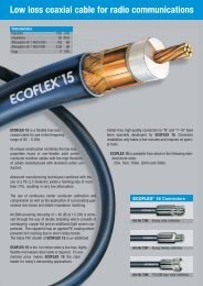
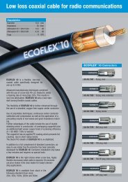
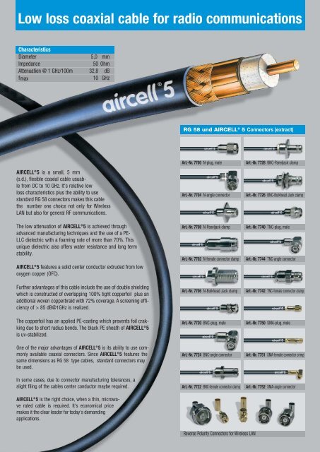
<strong>Low</strong> <strong>loss</strong> <strong>coaxial</strong> <strong>cable</strong> <strong>for</strong> <strong>radio</strong> <strong>communications</strong>CharacteristicsDiameter 5,0 mmImpedance50 OhmAttenuation @ 1 GHz/100m 32,8 dBfmax10 GHzRG 58 und AIRCELL ® 5 Connectors (extract)AIRCELL ® 5 is a small, 5 mm(o.d.), flexible <strong>coaxial</strong> <strong>cable</strong> usuablefrom DC to 10 GHz. It's relative low<strong>loss</strong> characteristics plus the ability to usestandard RG 58 connectors makes this <strong>cable</strong>the number one choice not only <strong>for</strong> WirelessLAN but also <strong>for</strong> general RF <strong>communications</strong>.The low attenuation of AIRCELL ® 5 is achieved throughadvanced manufacturing techniques and the use of a PE-LLC dielectric with a foaming rate of more than 70%. Thisunique dielectric also offers water resistance and long termstability.AIRCELL ® 5 features a solid center conductor extruded from lowoxygen copper (OFC).Further advantages of this <strong>cable</strong> include the use of double shieldingwhich is constructed of overlapping 100% tight copperfoil plus anadditional woven copperbraid with 72% coverage. A screening efficiencyof > 85 dB@1GHz is realized.The copperfoil has an applied PE-coating which prevents foil crakkingdue to short radius bends. The black PE sheath of AIRCELL ® 5is uv-stabilized.One of the major advantages of AIRCELL ® 5 is its ability to use commonlyavailable <strong>coaxial</strong> connectors. Since AIRCELL ® 5 features thesame dimensions as RG 58 type <strong>cable</strong>s, standard connectors maybe used.In some cases, due to connector manufacturing tolerances, aslight filing of the <strong>cable</strong>s center conductor maybe required.AIRCELL ® 5 is the right choice, when a thin, microwaverated <strong>cable</strong> is required. It's economical pricemakes it the clear leader <strong>for</strong> today's demandingapplications.Art.-Nr. 7700 N-plug, maleArt.-Nr. 7704 N-angle connectorArt.-Nr. 7708 N-Paneljack clampArt.-Nr. 7702 N-female connector clampArt.-Nr. 7706 N-Bulkhead Jack clampArt.-Nr. 7720 BNC-plug, maleArt.-Nr. 7724 BNC-angle connectorArt.-Nr. 7722 BNC-female connector clampArt.-Nr. 7728 BNC-Paneljack clampArt.-Nr. 7726 BNC-Bulkhead Jack clampArt.-Nr. 7740 TNC-plug, maleArt.-Nr. 7744 TNC-angle connectorArt.-Nr. 7742 TNC-female connector clampArt.-Nr. 7750 SMA-plug, maleArt.-Nr. 7751 SMA-female connector crimpArt.-Nr. 7752 SMA-angle connectorReverse Polarity Connectors <strong>for</strong> Wireless LAN
Technical dataAIRCELL is a registered trademark of SSB-Electronic GmbH.ConstructionCentre conductorsolid copper wire, OFCCentre conductor Ø1 x 1,05 mmDielectric Ø2,95 mmOuter conductor 1Copperfoil, PE coatedShielding factor 100%Outer conductor 2Copper braidShielding factor 72 %Sheathblack PVC, uv-resistantOuter diameter Ø5,0 mmMechanical specificationsMin. bending radius one single bending 2,5 cm15 repeated bendings 5 cmTemperature range storage -70 bis -85 °Cinstallation -40 bis +60 °Coperation -55 bis +85 °CFor your in<strong>for</strong>mationAttenuation (dB/100 m) @ 20°C1000 dBAIRCELL ® 5 RG 58/U ECOFLEX ® 10Capacity pF/m 82 102 78Velocity factor 0,82 0,66 0,85attenuation dB/100 m10 MHz 3,03 5,0 1,2100 MHz 9,78 17,0 4,0500 MHz 22,64 39,0 9,61000 MHz 32,84 54,6 14,23000 MHz 60,43 118 27,0Electrical specificationsImpedance @ 1 GHzDC-resistanceRF Peak VoltageRF Peak PowerCut-off FrequencyCentre conductorOuter conductor> 85 dB20,3 Ohm/km13,6 Ohm/km400 V1600 Watt33 GHz100 dB10 dBMax. power handling (W @40°C)10 MHz 1600100 MHz 510500 MHz 2201000 MHz 1502000 MHz 1003000 MHz 804000 MHz 705000 MHz 606000 MHz 60Typ. attenuation (dB/100m@20°C)5 MHz 2,1410 MHz 3,0350 MHz 6,86100 MHz 9,78144 MHz 11,80200 MHz 14,00300 MHz 17,29432 MHz 20,95500 MHz 22,64800 MHz 29,111000 MHz 32,841296 MHz 37,831500 MHz 40,991800 MHz 45,352000 MHz 48,092400 MHz 53,263000 MHz 60,434000 MHz 71,285000 MHz 81,186000 MHz 90,3910000 MHz 123,001 dB10 100 1000 10000Return <strong>loss</strong>Frequency (MHz)- 5 dB-10 dB-15 dB-20 dB-25 dB-30 dB-35 dB-40 dB0,0 0,5 1,0 1,5 2,0 2,5 3,0 3,5 4,0 4,5 5,0 5,5 6,0 6,5 7,0 7,5 8,0 8,5 9,0 9,5 10,0Frequency (GHz)Due to production tolerances the RTL may have different characteristics