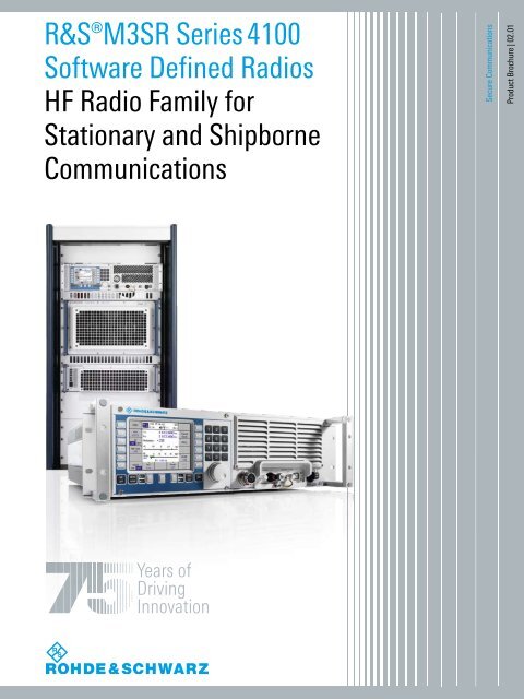
R&S®M3SR Series 4100 Software Defined Radios HF Radio Family ...
R&S®M3SR Series 4100 Software Defined Radios HF Radio Family ...
R&S®M3SR Series 4100 Software Defined Radios HF Radio Family ...
- No tags were found...

You also want an ePaper? Increase the reach of your titles
YUMPU automatically turns print PDFs into web optimized ePapers that Google loves.
R&S®M3SR<strong>Series</strong> <strong>4100</strong><strong>Software</strong> <strong>Defined</strong><strong><strong>Radio</strong>s</strong>Key features andbenefitsUnrivaled radio parametersJJ Collocation capability due to excellent receiverspecificationsJJ Selective level control for optimum transmit power(option)JJ Frequency-agile pre-/postselectors improve thelarge- signal characteristics (option)JJ Digital IF and audio signal processingFlexible range of applicationsJJ Three power classes and suitable line of accessoriesJJ Local or remote operationJJ Power supplies for all standard electrical networksJJ <strong>Software</strong> defined radio systemSecure communicationsJJ EPM (ECCM) method for secure and jam-restistant voiceand data linksJJ Powerful crypto algorithmJJ Management of "black" keys offers additional securityJJ Data link capability in line with STANAG 5511 andSTANAG 5522JJ Centralized network, crypto, and frequency managementcapabilities for configuring Rohde & Schwarz radio networksEasy operationJJ Clear status displayJJ Preconfigured menusJJ Remote control access with different levels ofauthorizationLow maintenance effortJJ Rugged design, suitable even for difficult environmentalconditionsJJ Powerful built-in test (BIT)JJ Excellent reliabilityFuture-proof and safe investmentJJ Standards from the "<strong>HF</strong> house" can be upgraded assoftware optionJJ Future changes in standards can be taken into account inproduct and program planningJJ Low life-cycle costsState-of-the-art secureradiocommunicationsRohde & Schwarz R&S®M3SR <strong>Series</strong> <strong>4100</strong> <strong>Software</strong> <strong>Defined</strong> <strong><strong>Radio</strong>s</strong> 3
Unrivaled radioparametersA high frequency (<strong>HF</strong>) radio channel is a transmissionmedium that is characterized by time variance,low signal-to-noise (S/N) ratios, Doppler effects andmultipath propagation. However, <strong>HF</strong> allows worldwidecommunications due to its unique propagationcharacteristics. To obtain usable signals, the operatingfrequencies and antennas as well as the radioparameters such as sensitivity, selectivity and noisesuppression are essential.Collocation capability due to excellent receiverspecificationsSimultaneous operation of multiple radio lines on boardships is extremely challenging in terms of the collocationcapability of the radios due to the spatial proximityof the radios and low antenna decoupling values. However,due to the outstanding specifications of the radiosof the R&S®M3SR <strong>Series</strong> <strong>4100</strong> (with the optional additionof digitally tuned <strong>HF</strong> filters), such challenges are easilysurmounted. The R&S®M3SR <strong>Series</strong> <strong>4100</strong> radios fulfillthe requirements stipulated in STANAG 4203, AnnexesB+C. For <strong>HF</strong> parameters such as 2nd and 3rd order intercept,desensitization and crossmodulation immunity, theR&S®M3SR <strong>Series</strong> <strong>4100</strong> sets new standards. For example,even without preselection the receiver provides 3rd orderintercept (IP3) of typically >40 dBm. This parameter isparticularly important in cases where very low amplitudesignals must be reliably detected in the simultaneous presenceof high-power interference from nearby transmittersystems.Selective level control for optimum transmit power(option)In real-world applications, mutual influences betweenadjacent transmitter lines due to low antenna decouplingvalues or close frequency spacing often result in overloadingof transmitter output stages and thus to a power reductiondue to reflected <strong>HF</strong> power. The optional selectivedirectional coupler available in the power amplifiers makesit possible to perform narrowband weighting of the transmitsignal and the reflected antenna power. This meansthat the transmitter power control of the transmitter linesis not influenced during normal operation.Frequency-agile pre-/postselectors improve the largesignalcharacteristics (option)The optional <strong>HF</strong> pre-/postselectors are steep-edged bandpassfilters with a relative bandwidth of a few percentwhich work at the transmitter and receiver ends. They canbe precisely set to the relevant operating frequencies. The<strong>HF</strong> pre-/postselectors influence the performance of theradios in two ways. On the one hand, they increase the TXphase noise to values better than typ. –165 dBc/Hz. On theother, they further significantly increase the large-signalcharacteristics of the receive section, i.e. crossmodulationimmunity, desensitization or 2nd and 3rd order interceptpoints. The <strong>HF</strong> pre-/postselector in the R&S®M3SR<strong>Series</strong> <strong>4100</strong> supports frequency hopping.Digital IF and audio signal processingThe R&S®M3SR <strong>Series</strong> <strong>4100</strong> combines the unmatcheddynamic range of radios with analog mixers with the latestin digital IF and audio signal processing. The second IFfrequency of 48 kHz is sampled, digitized and processedusing digital signal processors. This means that a widerange of IF bandwidths is available in all modes with highselectivity and optimized for voice and data communications.Digital signal processing also provides functions fornoise suppression.4
Flexible range ofapplicationsThree power classes and suitable line of accessoriesThe output power that is required of <strong>HF</strong> transceivers ishighly dependent on the particular application scenario.The radios of the R&S®M3SR <strong>Series</strong> <strong>4100</strong> are available inpower classes of 150 W, 500 W and 1000 W. For radio applicationson ship and shore, broadband radio systems arealso available with up to 32 radio lines and an output powerof up to 4 kW. The R&S®M3SR <strong>Series</strong> <strong>4100</strong> also includesa separate receiver as required in split-site applications, forexample. The product portfolio is rounded out by systemcomponents such as antenna tuning units (ATUs) and dipoleantennas from Rohde & Schwarz.Local or remote operationSuitable operating concepts are available to meet any requirement.The R&S®GB4000C control units for local orremote operation are equipped with a high-resolution 5"liquid crystal display which provides excellent readabilityeven under poor lighting conditions. The ability to adjustthe contrast and brightness as well as illuminated keysmake it much easier to read off information. Hardkeysand softkeys plus a clearly designed user interface ensureease of use when controlling the radio. <strong>Software</strong> definedremote control via the serial RS-232-C interface or viaEthernet is another alternative.Power supplies for all standard electrical networksFor the 500 W and 1000 W transceiver systems of theR&S®M3SR <strong>Series</strong> <strong>4100</strong>, Rohde & Schwarz offers a numberof power supplies to handle all of the electrical networksencountered in real-world scenarios. These power supplieshave high efficiency and excellent power factor compensation.<strong><strong>Radio</strong>s</strong> from Rohde & Schwarz areused on board of the ADCF frigateof the Royal Netherlands Navy<strong>Software</strong> defined radio systemAll of the software components can be loaded into theradio using the R&S®RNMS3000 network managementsystem. Relevant software packages are available fordownloading. This means that you can expand the functionalitywithout having to open the radio or exchange anyhardware modules. You can query the current softwarestatus via the local control unit on the radio or remotelyin the form of a list (inventory). The inventory contains theversion of the radio software and its components.Rohde & Schwarz R&S®M3SR <strong>Series</strong> <strong>4100</strong> <strong>Software</strong> <strong>Defined</strong> <strong><strong>Radio</strong>s</strong> 5
SecurecommunicationsEPM (ECCM) method for secure and jam-restistantvoice and data linksIn order to protect communications against tappingand spoofing, transmissions are encrypted (COMSEC).Electronic protection measures (EPM) based on frequencyhopping effectively protect radio links against spoofingand jamming as well as against unintentional interferencesuch as changing physical propagation conditions.Rohde & Schwarz developed its powerful R&S®SECOM-Hfrequency hopping method especially for the <strong>HF</strong> range.This method enables secure radiocommunications betweenarmy and navy over significant distances and inchallenging terrains.Powerful crypto algorithmThe COMSEC/TRANSEC crypto algorithm was developedby Rohde & Schwarz. It supports key lengths up to 256bits. R&S®SECOM-H also includes a suite of modem waveformsthat exhibit different degrees of immunity againstDoppler effects and multipath propagation as are typical ofshortwave links. R&S®SECOM-H was designed to allow securetransmission of voice (vocoder at 1200 bps/2400 bps)and data (300 bps to 2400 bps). R&S®SECOM-H is usefulfor planning secure radio networks for point-to-point,point-to-multipoint and broadcast operation.Management of "black" keys offers additionalsecurityKeys are generated using the R&S®CP3000 keymanagement system. Keyset files are transmitted bythe R&S®CP3000 to the R&S®RNMS3000 networkmanagement system using an additional asymmetric keyprotection key. This means that exclusively "black" keys aretransported. Using the mission planner module, it is possibleto set up secure R&S®SECOM-H radio networks consistingof the R&S®M3SR <strong>Series</strong> <strong>4100</strong> and the R&S®M3TR.The R&S®SECOM-H radio configuration from the missionplanner can be loaded into the radio via Ethernet ora fillgun. As an extension to its radio product portfolio,Rohde & Schwarz offers system components with frequencyhopping capability such as amplifiers and antenna tuningunits to allow the setup of radio lines with frequencyhopping and up to 1000 W output power.Data link capability in line with STANAG 5511 andSTANAG 5522<strong><strong>Radio</strong>s</strong> often need to fulfill special requirements if they areto be used for tactical data links. Requirements include:JJ Fast switchover times between transmit and receivemodeJJ Special IF filter characteristicsJJ Fast automatic level controlThe R&S®M3SR <strong>Series</strong> <strong>4100</strong> <strong>HF</strong> transceiver systems areideally suited for applications involving tactical data links.With their excellent specifications, they meet all requirementsof the LINK methods:JJ STANAG 5511/MIL-STD-203-1A: LINK-11JJ STANAG 5522: LINK-22 (fixed frequency)6
R&S®RNMS3000: centralized network, crypto, andfrequency management capabilities for configuringRohde & Schwarz radio networksToday's armed forces apply communications planning inorder to transform their combat radio equipment into arobustly networked communications system. They need asystem that optimally supports the forces in accomplishingthe mission at hand. R&S®RNMS3000 provides militaryleaders with the software they need to create such a systemfrom their Rohde & Schwarz radios.To provide mission-tailored and secure radio communicationsnetworks, the R&S®RNMS3000 software systemdoes the following:JJ Manages security keysJJ Makes frequency assignmentsJJ Establishes logical netsIn particular, the R&S®RNMS3000's capability to manageNATO-specific waveforms, as well as general <strong>HF</strong>waveforms and Rohde & Schwarz proprietary waveforms,accents its broad scope of application.The R&S®RNMS3000 software supports centralized systemmanagement, i.e. where one central organizationalunit performs all mission planning steps, as well as decentralizedmanagement, where the various configurationsteps are accomplished at different echelons in the militaryhierarchy.Moreover, the R&S®RNMS3000 software system providesa single data set that – when distributed to the required radioseither via a fill device or a LAN connection – includesall parameters relevant to immediately using the radioswithin the defined logical network structure.Centralized network, crypto, and frequency management capabilitiesR&S®RNMS3000radio networkmanagementsystemKey managementFrequency managementNetwork managementNetwork loadingBrigadenetworksPlatoonradionetworksSquadradionetworksOperational areaOperating timeRohde & Schwarz R&S®M3SR <strong>Series</strong> <strong>4100</strong> <strong>Software</strong> <strong>Defined</strong> <strong><strong>Radio</strong>s</strong> 7
Easy operationThe user-oriented design of theGUI allows intuitive operation ofthe radioClear status displayAll required settings on the radio can be made locallyusing the optional R&S®GB4000C (model 32/35) local controlpanel. Status information such as the operating modeis displayed in the header area of the user interface. Thesestatus displays keep the user informed at a glance aboutthe current mode setting on the radio or the user's accessauthorization. This increases the operational reliability andreduces the time needed for new users to get familiar withthe radio.Preconfigured menusThe user interface for the R&S®M3SR radio family hasclearly structured menus that are divided by function. Eachoperating mode is set using preconfigured menus (presetpages). The R&S®M3SR <strong>Series</strong> <strong>4100</strong> can manage up to 100preconfigured menus. The configuration is generated usingthe R&S®RNMS3000 network management system.The preset pages can then be loaded into the radio viaLAN, RS-232-C or a fillgun.Remote control access with different levels ofauthorizationUsing an R&S®GB4000C (model 33/36) remote controlunit, it is possible to operate additional R&S®M3SR<strong>Series</strong> <strong>4100</strong> radio systems if they are part of an IP network.Larger systems with multiple control units require thecontrol of access rights. These access rights, known assessions, are made available by the remote control unitand can be specified by the user. The status is shown onthe display of the remote control unit.Remote control conceptControl site<strong>Radio</strong> siteEthernetHub/routerLANHub/routerEthernet8
Future-proof andsafe investmentStandards from the "<strong>HF</strong> house" can be upgraded assoftware optionJJ <strong>HF</strong> modems STANAG 4285, STANAG 4415,STANAG 4539, Annex B, MIL-STD-188-110BJJ Automatic link establishment (ALE), 2nd generation,MIL-STD-188-141B, App. A + BJJ Automatic link establishment (ALE), 3rd generation,STANAG 4538 (fast link setup)JJ Data link protocols LDL, HDL from STANAG 4538(without IP interface)Future changes in standards can be taken intoaccount in product and program planningThe "<strong>HF</strong> house" is a structured overview of different <strong>HF</strong>standards that have been ratified by the NATO countries.These are living standards which are revised at regularintervals. These changes are taken into account as partof the product and program planning for the R&S®M3SR<strong>Series</strong> <strong>4100</strong> and provided to customers in the form of softwareupdates.STANAG 4203STANAG 4415STANAG 4285STANAG 4529STANAG 4539MIL-STD-188-110A/BMIL-STD-188-141A/BSTANAG 5066STANAG 4538STANAG 4444ACSALEARCSARQALMEPM (ECCM)LSU2G/3GS xxxxMS xxxxTechnical standards for <strong>HF</strong> radio equipmentNATO robust waveform, 75 bit/sSingle tone modem, up to 3600 bit/sSingle tone modem, up to 1800 bit/sSingle tone modem, up to 12800 bit/sSingle tone modem, up to 12800 bit/s(≈ STANAG 4539)Automatic link establishmentProfile for <strong>HF</strong> radio data communicationsAutomated radio control system (ARCS)NATO <strong>HF</strong> slow hopping waveformAutomatic channel selectionAutomatic link establishmentAutomatic radio control systemAutomatic repeat requestAutomatic link maintenanceElectronic protective measuresLink setupSecond/third generationSTANAG xxxxMIL-STD xxxxLow life-cycle costsJJ User-friendly operating concept reduces training costsJJ High MTBF (in line with MIL-HDBK-217F) and low MTTRvalues (
Sample applicationIntegrated navalcommunicationssystemsIntegrated communications systems (ICS) aremandatory for the efficient command and controlof modern ships. They must be able to manageship-internal communications as well as providethe reliable exchange of strategic, tactical andadministrative information between ships and alsonaval shore stations.R&S®SIMCOS II is a signal management and controlsystem which, when combined with a digital communicationsnode, allows the flexible and therefore efficient interconnectionof audio consoles, radios, modems, encryptiondevices, and antennas to form complete radio lines.The management and control of radio lines includes thewizard-supported creation of communications plans, theconfiguration of devices under remote control, and continuousmonitoring, thus providing a detailed overview ofthe status of all radio line components.The R&S®STANAG5066 and R&S®MMHS messagehandling systems can be seamlessly integrated intoR&S®SIMCOS II.Rohde & Schwarz contributions to combat systemsCMS from Third PartiesMessage handling system¸MMHS ¸STANAG 5066 ¸PostMan IIIntegrated communications system (ICS)Internal/external voice & data communications systemManagement systemInterfaces to applications¸SIMCOS IIUser managementProtocolsSTANAG 5066R&S protocols(e.g. IP over air)Standardinterfaces(e.g. Link 11,Link Y/22)AudiounitsEvent logFrequency-antenna management(FAM)CommPlan managementRemote controlCommunications equipmentDigital communication node (DCN)Voice encryptionDICSELCRODAT 4-2 ¸MMC 3000 Others<strong>Radio</strong> and modem equipment<strong>HF</strong> radios V/U<strong>HF</strong> radios SATCOM Data modems Antennas /ATUs12
Systemconfiguration<strong>HF</strong> transmit/receivebroadband systemIt is a flexible and modular multiline radio systemfor the <strong>HF</strong> frequency range. The applications rangefrom shore radio stations to navy ships with up to 32radio lines.The system's excellent scalability makes it suitable foruse on board a wide range of ships, from Corvette-classvessels to aircraft carriers. The system offers the fullrange of R&S®M3SR <strong>Series</strong> <strong>4100</strong> modulation modes andwaveforms, from simple SSB operation and ALE to EPM(ECCM) radio line. Intelligent radio line management providesflexible and dynamic allocation of transmit power,from a few watts to several kilowatts, to support a varietyof military missions.<strong>HF</strong> broadband system - a future-proof investmentThe system is based on the principle of combining shipboard<strong>HF</strong> radio lines with the help of highly linear, passiveline couplers and then transmitting the combined signalusing a broadband antenna system. The system coversthe entire <strong>HF</strong> frequency band from 2 MHz to 30 MHz andconsists of separate broadband antennas, each covering asubband. A diplexer or triplexer selects each antenna segment.The antenna system contains no switched elements. Thebroadband capability of the antennas eliminates the needfor antenna tuning units. Since only passive componentssuch as couplers and filters are used, the result is an extremelylow-maintenance system with superior reliability.Example: 16-line <strong>HF</strong> broadband systemRohde & Schwarz R&S®M3SR <strong>Series</strong> <strong>4100</strong> <strong>Software</strong> <strong>Defined</strong> <strong><strong>Radio</strong>s</strong> 13
User interface of theR&S®GV4190D powermanagement unitLocal controlBroadband blocks can be locally configured and controlledwith the R&S®GB4000C local control panel. The PMU offersa selection of operational modes to ensure a definedlogical allocation between the receivers/exciters and thepower amplifiers. These modes are especially suitable forlocally controlling 4 kW transmitter/receiver systems suchas those deployed at shore stations.Flexible, logical allocation of the connectedreceivers/exciters and power amplifiersThrough the right combination of coherent and non-coherentsignal paths, the number of radio lines in operationand their output power can be varied over a wide range.Coherent mode means that the output power of two radiolines can be arithmetically added (without taking intoaccount coupler loss). This requires that both line couplerinput signals have identical frequencies and phase angles.If the input signal frequencies or phase angles are notidentical, this is referred to as non-coherent mode andresults in attenuation of the input power by 3 dB(= factor of 2).4 × 1 kW radio lines and power management unit form a broadband blockBroadband antenna systemR&S®FK41944 kW combinerR&S®FK41922 kW combinerR&S®FK41922 kW combinerR&S®VK4190power amplifierR&S®VK4190power amplifierR&S®VK4190power amplifierR&S®VK4190power amplifierR&S®GV4190 PMUConnection to RXantenna multicouplerf1ExciterR&S®GX<strong>4100</strong>R&S®GX<strong>4100</strong>R&S®GX<strong>4100</strong>f2 exciterf3 exciterf4 exciterAF Lines toIntercom System<strong>HF</strong> linesControl bus systemMonitoring of combinersRohde & Schwarz R&S®M3SR <strong>Series</strong> <strong>4100</strong> <strong>Software</strong> <strong>Defined</strong> <strong><strong>Radio</strong>s</strong> 15
System configuration<strong>HF</strong> transmit/receivebroadband systemThe R&S®GV4190D power managementunit connects the externalexciters and power amplifiers viaEMC-compliant fiber-optic controlbus lines. This makes it easy to integratethe <strong>HF</strong> broadband systeminto standard 19-inch racksThe <strong>HF</strong> broadband system can be expanded to support up to 32 radio linesBroadband antenna systemTerminal,control systemMedium bandLow bandHigh bandR&S®FK2950antenna triplexerR&S®FK4194combinerR&S®FK4194combinerR&S®FK4194combinerR&S®FK4194combinerR&S®FK4194combinerR&S®FK4194combinerR&S®FK4194combinerBroadbandblock(4 × 1 kW)Broadbandblock(4 × 1 kW)Broadbandblock(4 × 1 kW)Broadbandblock(4 × 1 kW)Broadbandblock(4 × 1 kW)Broadbandblock(4 × 1 kW)Broadbandblock(4 × 1 kW)Broadbandblock(4 × 1 kW)PMUPMUPMUPMUPMUPMUPMUPMU<strong>HF</strong> linesMonitoring of combinersLAN connection16
R&S®M3SR<strong>Series</strong> <strong>4100</strong><strong>Software</strong> <strong>Defined</strong><strong><strong>Radio</strong>s</strong>Logistical structureBase radio modelsThe logistical structure of the R&S®M3SR <strong>Series</strong> <strong>4100</strong>is based on radio models that are available for theR&S®EK<strong>4100</strong> receiver, the R&S®GX<strong>4100</strong> exciter and theR&S®XK4115 150 W transceiver. The base radio modelsare also available in ruggedized versions (splashproof IP32front panel). The software for these base models which areknown as R&S®MR<strong>4100</strong>x can be ordered in the form of "A"software (with no export restrictions) or "D" software (requiringan export license).Hardware and software optionsTo configure individual hardware and software optionsplus the appropriate radio software, refer to the next chapterfrom page 24 onward.R&S®M3SR <strong>Series</strong> <strong>4100</strong> radio configurationR&S®EK<strong>4100</strong>A/D(configured)R&S®XK4115A/D(configured)R&S®GX<strong>4100</strong>A/D(configured)R&S®GV4190D(configured)R&S®DS<strong>4100</strong>A/Dradio softwareR&S®DS<strong>4100</strong>A/Dradio softwareR&S®DS<strong>4100</strong>A/Dradio softwareR&S®DS<strong>4100</strong>A/DR&S®DS<strong>4100</strong>Dradio software<strong>Software</strong> options<strong>Software</strong> options<strong>Software</strong> options<strong>Software</strong> optionsHardware optionsHardware optionsHardware optionsHardware optionsR&S®MR<strong>4100</strong>EVLF-<strong>HF</strong> receiver(base unit)R&S®MR<strong>4100</strong>X<strong>HF</strong> transceiver(base unit)R&S®MR<strong>4100</strong>G<strong>HF</strong> receiver/exciter(base unit)R&S®MR<strong>4100</strong>G-BPower management <strong>HF</strong> exciter unitincl. receiver/exciter(base unit)(base unit)Rohde & Schwarz R&S®M3SR <strong>Series</strong> <strong>4100</strong> <strong>Software</strong> <strong>Defined</strong> <strong><strong>Radio</strong>s</strong> 17
VLF-<strong>HF</strong> receiverR&S®EK<strong>4100</strong>A/DThe type designation and the associated order number foran R&S®EK<strong>4100</strong>A/D base unit that is custom-configuredare order-specific. This makes it possible to clearly identifyany customized receiver with all of its options using aunique order number.A receiver can be operated on 28 V DC voltage (19 V to31 V) or 230 V AC voltage (90 V to 264 V, 50/60 Hz).R&S®EK<strong>4100</strong>A/D¸EK<strong>4100</strong>A/D VLF-<strong>HF</strong> receiver: front viewR&S®DS<strong>4100</strong>A/Dradio software<strong>Software</strong> optionsHardware optionsVLF-<strong>HF</strong> receiverR&S®MR<strong>4100</strong>E(base unit)Control panelFill guninterfaceHeadsetconnectorIndicators Power ON/OFFErase¸EK<strong>4100</strong>A/D VLF-<strong>HF</strong> receiver: rear viewAntenna interfaces (RX)Mains DC input ReferencefrequencyinputAudio/PTTinterfaceDatainterfaceRS-232-CremotecontrolLANremote controlSW download18
150 W transceiverR&S®XK4115A/DThe final type designation and the associated order numberfor an R&S®XK4115A/D base unit that is custom-configuredare order-specific. This makes it possible to clearlyidentify any customized transceiver with all of its optionsusing a unique order number.A transceiver can be operated on 28 V DC voltage (19 V to31 V) or with an external R&S®IN4000A power supply on230 V AC voltage (100 V to 240 V, 50/60 Hz).R&S®XK4115A/D¸XK4115A/D transceiver with external power supply: front viewR&S®DS<strong>4100</strong>A/Dradio software<strong>Software</strong> optionsHardware optionsR&S®MR<strong>4100</strong>X<strong>HF</strong> transceiver(base unit)R&S®IN4000Apower supplyControl panelFill guninterfaceHeadsetconnectorIndicators Power ON/OFFErase¸XK4115A/D transceiver with external power supply: rear viewDC outputOptical interface toantenna tuning unit (ATU)Antenna interface (RX)MainsAntenna interface(TX/RX)DC inputReferencefrequencyinputAudio/PTTinterfaceDatainterfaceRS-232-CremotecontrolLANremote controlSW downloadRohde & Schwarz R&S®M3SR <strong>Series</strong> <strong>4100</strong> <strong>Software</strong> <strong>Defined</strong> <strong><strong>Radio</strong>s</strong> 19
500 W/1000 Wtransceiver systemsTo cover large distances, flexible system solutions withan output power of 500 W and 100 W are offered. Thesesolutions furthermore provide exceptionally high radio linkavailability − even under moderate propagation conditions.They provide higher signal-to-noise ratios as requiredwhen transmitting at high data rates, for applications inworldwide embassy radio systems, in civil ATC systems orin the military. It also goes without saying that these systemsoffer frequency hopping capability.A 500 W or 1000 W transceiver system consists of thefollowing components:JJ R&S®GX<strong>4100</strong>A/D exciter/receiverJJ R&S®VK4150/4190 power amplifierJJ R&S®IN4150/4190 power supplyTransceiver system¸GX<strong>4100</strong>A/D receiver/exciter: front viewR&S®GX<strong>4100</strong>A/Dreceiver/exciter(base unit)R&S®VK4150/4190power amplifierR&S®IN4150/4190power supplyControl panelFill guninterfaceHeadsetconnectorIndicators Power ON/OFFEraseR&S®GX<strong>4100</strong>A/DR&S®DS<strong>4100</strong>A/Dradio software¸GX<strong>4100</strong>A/D receiver/exciter: rear viewOptical interface to power amplifierAntenna interfaces(RX) (TX/RX)<strong>Software</strong> optionsHardware optionsR&S®MR<strong>4100</strong>G<strong>HF</strong> receiver/exciter(base unit)DC inputReferencefrequencyinputAudio/PTTinterfaceDatainterfaceRS-232-CremotecontrolLANremote controlSW download20
Transceiver systemR&S®GX<strong>4100</strong>A/Dreceiver/exciter(base unit)R&S®VK4150/4190power amplifierR&S®IN4150/4190power supplyR&S®VK4150/VK4190 power amplifiersThe digitally controlled R&S®VK4150/VK4190 power amplifiersare available in a standard version or a special versionwith built-in receiver input protection. This option reliablyprotects the receiver input from destruction in the presenceof <strong>HF</strong> interference on the antenna (caused by nearbytransmitters) up to 100 V rms (corresponding to a powerof 200 W into 50 Ω).R&S®VK4150/VK4190 with built-in receiver input protectionshould be selected whenever undisturbed reception of usefulsignals is required under such extreme conditions.CharacteristicsJJ Available for 500 W and 1000 W transceiver systemsJJ Rugged design, high MTBFJJ Special version with built-in receiver input protectionavailableJJ "Selective level control" option prevents power controlfrom being affected during normal operation by in-servicetransmitters located nearbyR&S®VK4150/VK4190 power amplifier: front viewR&S®VK4150/VK4190 power amplifier: rear viewControl interface to power supplyControl interfaceto ATUDC output to exciterOptical interfaceto exciterDC inputRF output powerRF input powerRohde & Schwarz R&S®M3SR <strong>Series</strong> <strong>4100</strong> <strong>Software</strong> <strong>Defined</strong> <strong><strong>Radio</strong>s</strong> 21
Transceiver systemR&S®GX<strong>4100</strong>A/Dreceiver/exciter(base unit)R&S®VK4150/4190power amplifierR&S®IN4150/4190power supplyStandard power supplies for the500 W/1000 W transceiver systemsJJ CE conformity in line with EN 60945 and ETSIEN 300373-1/-2/-3JJ Compliant to MIL-STD-1399, section 300A and STANAG1008, edition 8JJ Different models available for all conventional electricalnetworksJJ Excellent efficiency (>85%)JJ State-of-the-art power factor compensation (>95%)JJ Automatic switchover between AC and battery supply incase of power failureJJ Compact 19" design, only three height units per radioR&S®IN4150/4190 power supply: front viewIndicatorsPower ON/OFFR&S®IN4150/4190 power supply: rear viewMain circuit breakerControl interface toRF power amplifierMainsBackupbatteryDC outputR&S®IN41x0/BV4190 power supplyR&S®IN4150/4190 power supply (above) in 3-phase operation at 440 Vwith external R&S®BV4190 transformer (bottom)22
Powermanagement unitR&S®GV4190DThe type designation and the associated order number foran R&S®GV4190D base unit that is custom-configured areorder-specific. This makes it possible to clearly identify anycustomized power management unit with all of its optionsusing a unique order number.R&S®GV4190D¸GV4190D power management unit: front viewR&S®DS<strong>4100</strong>Dradio software<strong>Software</strong> optionsHardware optionsR&S®MR<strong>4100</strong>G-BPower management unitincl. receiver/exciter(base unit)Control panelFill guninterfaceHeadsetconnectorIndicators Power ON/OFFErase¸GV4190D power management unit: rear viewMultipurposeinput/outputRF outputs ofotherreceivers/excitersGroundconnectorRF outputs toother externalpower amplifiersAntenna (RX)GPS interfaceMonitoring portsto powercombiners,diplexer, triplexerControl interfacesto otherreceivers/excitersreserved for8 kW mode(future)LANremote controlSW downloadControl interfacesto otherpower amplifiersDC inputReferencefrequencyinputAudio/PTTinterfaceDatainterfaceControl interfaceto power amplifierRS-232-CremotecontrolRohde & Schwarz R&S®M3SR <strong>Series</strong> <strong>4100</strong> <strong>Software</strong> <strong>Defined</strong> <strong><strong>Radio</strong>s</strong> 23
Hardware optionsfor receiver, exciterand transceiver¸GB4000C local control panel¸FK4120 digitally tuned <strong>HF</strong> selector¸GB4000C local control panelJJ Compact dimensionsJJ Rugged designJJ Graphical color LCDJJ Internal built-in test (BIT)The R&S®GB4000C local control panel (model 32/35) isused to operate and monitor the radio. The 5" LC displayprovides good readability even under poor lighting conditions.Hardkeys and softkeys as well as a clearly designeduser interface ensure ease of use when controlling theradio.¸FK4120/4140 digitally tuned <strong>HF</strong> selectorsJJ Five-circuit lowpass filter (0 Hz to 1.5 MHz) for receivefrequencies below 1.5 MHzJJ Digitally tuned tracking bandpass filters (1.5 MHz to30 MHz) with 20 dB or 40 dB edge steepness at 10 % frequencyoffsetJJ Automatic tracking in both receive and transmit modesJJ Input voltage protection up to 200 V (V ) rmsJJ Frequency hopping capability in line with R&S®SECOM-HThe R&S®FK4120/FK4140 digitally tuned <strong>HF</strong> selectors areoptional plug-in modules for the radios of the R&S®M3SR<strong>Series</strong> <strong>4100</strong>. They increase the selectivity of the transmitand receive paths. Receiver parameters such as 2nd and3rd order intercept, IF rejection, image-frequency rejectionand crossmodulation immunity are significantly improved.In the transmit direction, the TX phase noise is suppressedto produce typical values as low as –165 dBc/Hz.These digitally tuned <strong>HF</strong> selectors are recommended if youneed to receive low-amplitude signals in the simultaneouspresence of strong <strong>HF</strong> carrier signals. This is the casewhen multiple <strong>HF</strong> radio lines operate simultaneously andindependently of one another and reception should bepossible even if adjacent lines are transmitting.¸GS4102 NMEA (DSC) interface¸GS4102 NMEA (DSC) interfaceThe NMEA (DSC) interface is necessary when theR&S®M3SR <strong>Series</strong> <strong>4100</strong> transceiver systems are usedto forward distress calls that are located by an externalGMDSS monitoring and communications system. TheNMEA interface can be added to the R&S®XK4115A/D150 W transceiver or the R&S®GX<strong>4100</strong>A/D exciter for the500 W and 1000 W transceiver systems.24
<strong>Software</strong> optionsfor receiver, exciterand transceiverThe most noteworthy feature of the R&S®M3SR<strong>Series</strong> <strong>4100</strong> radios is that all of the functionality isalready contained in the radio software. Desiredfunctions are simply enabled on an applicationspecificbasis using option keys.R&S®GS4101S ALE-2G software(FED-STD-1045/1046/1049)R&S®GS4101S is the basic ALE software for the 2ndgeneration of automatic link establishment (ALE) systems.This software option provides support for theFED-STD-1045/1046/1049 and MIL-STD-188-141B, App.A+B standards. R&S®GS4101S can only be enabled inR&S®DS<strong>4100</strong>D.R&S®GS3001S SECOM-H EPM (ECCM) waveformThe R&S®SECOM-H EPM (ECCM) waveform has setnew standards in the area of secure communications.It uses a powerful crypto algorithm to provide the bestpossibleprotection against detection, tapping or jammingof radiocommunications. The keys required for theEPM (ECCM) method (COMSEC and TRANSEC) can beloaded into the radio using a fillgun. Alternatively, the keyscan also be loaded into the radio directly from a PC viathe LAN interface. R&S®GS3001S can only be enabled inR&S®DS<strong>4100</strong>D.R&S®GS4114S LINK softwareThe R&S®GS4114S LINK software makes the radio parameterscomply with the STANAG 5511, STANAG 5522, andMIL-STD-188-203-1A standards. External LINK-11 as wellas LINK-Y or LINK-22 modems (fixed frequency) can beconnected directly to the radio. The R&S®GS4114S LINKsoftware can only be enabled in R&S®DS<strong>4100</strong>D.The radio software can be orderedin the "A" version (without exportrestrictions) or the "D" version<strong>Software</strong> options(export license required)R&S®DS<strong>4100</strong>A/Dradio software<strong>Software</strong> optionsR&S®GS4101SALE-2G(FED-STD-1045/1046/1049)R&S®GS4155SALE-3GR&S®GS3001SSECOM-H*) only for 500 W and1000 W transceiver systemsR&S®GS4114SLINK softwareR&S®GM4120S<strong>HF</strong> modemR&S®GS4115Sselective level control *)FutureoptionsRohde & Schwarz R&S®M3SR <strong>Series</strong> <strong>4100</strong> <strong>Software</strong> <strong>Defined</strong> <strong><strong>Radio</strong>s</strong> 25
<strong>Software</strong> optionsfor receiver, exciterand transceiverR&S®GS4115S selective level controlIn real-world applications, mutual influences between adjacenttransmitter lines as a result of low antenna decouplingvalues or insufficient frequency spacing can causeoverloading of transmitter output stages as well as powerreductions due to reflected <strong>HF</strong> power. The optional selectivedirectional coupler in the power amplifiers makes itpossible to perform narrowband weighting of the transmitsignal and the reflected antenna power. This ensures thatthe transmitter power control is not influenced by extraneoussignals during normal operation. The R&S®GS4115Sselective level control can be enabled in R&S®DS<strong>4100</strong>Aand R&S®DS<strong>4100</strong>D.R&S®GM4120S <strong>HF</strong> modemThe STANAG 4285 <strong>HF</strong> modem is used primarily for broadcastingoperation and for ARQ-secured data transmission,typically in conjunction with an external STANAG 5066 application.The STANAG 4539 Annex B <strong>HF</strong> modem provides transmissiondata rates from 75 bits/s to 9600 bits/s. It is therecommended modem for new projects within NATO. Itautomatically sets the transmission data rate and is usedpreferably with the R&S®STANAG5066 data protectionprotocol. STANAG 4539 Annex B includes the followingmodem standards:JJ STANAG 4415JJ MIL-STD-188-110A, Part 5.3JJ STANAG 4539, Annex B, Part 4R&S®GM4120S can only be enabled in R&S®DS<strong>4100</strong>D.R&S®GS4155S ALE-3GALE-3G (automatic link establishment, 3rd generation) offerssignificant benefits compared to ALE-2G, includingsignificantly faster and more robust link setup. The layer2 protocols known as LDL (low latency data link protocol)and HDL (high rate data link protocol) have the benefit ofimproved robustness at low S/N values compared to conventionalprotocols. The data link protocols can be controlledusing serial data.The R&S®GS4155S option comprises the followingfunctions:JJ ALE-2G (FED-STD 1045/1046/1049)JJ ALE-3G (STANAG 4538, fast link setup)––LDL (low latency data link protocol)––HDL (high rate data link protocol)The R&S®GS4155S option can be activated in theR&S®DS<strong>4100</strong>D radio software only.26
Ordering informationR&S®M3SR <strong>Series</strong> <strong>4100</strong> power classesPlease note: all base units are also in ruggedized version availableR&S®EK<strong>4100</strong>A/D receiverR&S®XK4115A/D 150 W transceiver500 W transceiver systems 1000 W transceiver systemsR&S®GX<strong>4100</strong>A/D<strong>HF</strong> receiver/exciterR&S®GX<strong>4100</strong>A/D<strong>HF</strong> receiver/exciterR&S®VK4150500 W <strong>HF</strong> power amplifierR&S®VK41901000 W <strong>HF</strong> power amplifierR&S®IN4000A power supply(optional)R&S®IN4150 power supplyR&S®IN4190 power supplyR&S®EK<strong>4100</strong>A/D receiver Type Order no.Base unitsVLF-<strong>HF</strong> Receiver; AC/DC; without local control panel and radio software R&S®MR<strong>4100</strong>E 6118.9609.02VLF-<strong>HF</strong> Receiver; AC/DC; without local control panel and radio software; ruggedized version R&S®MR<strong>4100</strong>E 6118.9609.12<strong>Radio</strong> software<strong>Software</strong> CD without export restriction R&S®DS<strong>4100</strong>A 6119.7800.xx<strong>Software</strong> CD with export restriction R&S®DS<strong>4100</strong>D 6119.7900.xxHardware optionsLocal Control Panel (without audio; including software and LAN) R&S®GB4000C 6105.6006.32Local Control Panel (without audio; including software and LAN), ruggedized version R&S®GB4000C 6105.6006.35Digitally Tuned <strong>HF</strong> Selector, 20 dB, operates in transmitting and receiving section R&S®FK4120 6119.5007.02Digitally Tuned <strong>HF</strong> Selector, 40 dB, operates in transmitting and receiving section R&S®FK4140 6119.6003.02NMEA (DSC) Interface, for connection to an external DSC controller (GMDSS) R&S®GS4102 6119.3504.02DSP Board, hardware platform for embedded <strong>HF</strong> modem (R&S®MR<strong>4100</strong>E, model 02 only) R&S®GS4105 6119.2108.02<strong>Software</strong> options (option keys)ALE-2G (FED-STD-1045/1046/1049) R&S®GS4101S 6120.6003.02ALE-2G (FED-STD-1045/1046/1049), STANAG 4538 (ALE-3G, LP, HDL, LDL) R&S®GS4155S 6142.7560.02LINK software, tactical data link capability in line with STANAG 5511, STANAG 5522 (fixed frequency), LINK-Y R&S®GS4114S 6142.7619.02<strong>HF</strong> Modem, single tone modems in line with STANAG 4285, STANAG 4539 annex B, MIL-STD-188-110B R&S®GM4120S 6142.7519.02Mating connector setMating Connector Set for R&S®MR<strong>4100</strong>E R&S®ZF4101 6120.5007.05Rohde & Schwarz R&S®M3SR <strong>Series</strong> <strong>4100</strong> <strong>Software</strong> <strong>Defined</strong> <strong><strong>Radio</strong>s</strong> 27