
You also want an ePaper? Increase the reach of your titles
YUMPU automatically turns print PDFs into web optimized ePapers that Google loves.
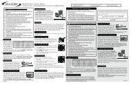
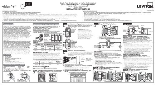
WARNINGS AND CAUTIONS:• To be installed and/or used in accordance with appropriate electrical codes and regulations.• If you are unsure about any part of these instructions, consult a qualified electrician.• To avoid overheating and possible damage to this device and other equipment, do not install to control a receptacle, fluorescent lighting, a motor- or a transformer operated appliance.• Use with magnetic low voltage transformers, incandescent, or 120V halogen fixtures only. Use a <strong>Leviton</strong> electronic low voltage dimmer to control electronic (solid state) low voltagetransformers.• When magnetic low voltage circuits are operated at a dim level, with all lamps inoperative, excess current may flow through the transformer. To avoid possibletransformer failure due to overcurrent, use a transformer that incorporates thermal protection or a fuse at the primary windings.• Vizia RF + TM dimmers are not compatible with standard 3-way or 4-way switches. They must be used with compatible Vizia + TM or Vizia RF + TM controllers for multi-location dimming.Single Pole (One location) or 3-Way (Multi-location)Scene Capable Magnetic Low Voltage DimmerCat. No. <strong>VRM10</strong>-<strong>1L</strong>, 1000VA (Lighted)120VAC, 60HzInstallation InstructionsDI-000-<strong>VRM10</strong>-02AWARNINGS AND CAUTIONS:• Use only one (1) Vizia RF + Magnetic Low Voltage Dimmer in a multi-location circuit with up to 9 coordinating remotes (without LEDs) or up to 4 matching remotes(with LEDs). The remote(s) will turn the load on (“at the level selected” for dimmers only) at the control.• Total minimum load must exceed 40W.• Dimmer may feel warm to the touch during normal operation.• Recommended minimum wall box depth is 2-1/2".• Maximum wire length from dimmer to all installed remotes cannot exceed 300 ft.• Disconnect power at circuit breaker or fuse when servicing, installing or removing fixture.• Use this device only with copper or copper clad wire. With aluminum wire use only devices marked CO/ALR or CU/AL.INTRODUCTION<strong>Leviton</strong>’s Vizia RF + TM components are designed to communicatewith each other via Radio Frequency (RF) to provide remote controlof your lighting. Using RF technology allows <strong>Leviton</strong> to provide thegreatest signal integrity possible. Each module in <strong>Leviton</strong>’sVizia RF + TM component line is a Z-Wave ® enabled device. In aZ-Wave ® network, each device is designed to act as a router. Theserouters will re-transmit the RF signal from one device to anotheruntil the intended device is reached. This ensures that the signalis received by its intended device by routing the signal aroundobstacles and radio dead spots. The Scene Capable Magnetic LowVoltage Dimmer is compatible with any Z-Wave ® enabled network,regardless of the manufacturer and can also be used with otherdevices displaying the Z-Wave ® logo.CAUTION:Remember to exercise good common sense when using the Timerfeatures of your remote, especially when scheduling unattendeddevices. There can be some unexpected consequences if not usedwith care. For example, an empty coffee pot can be remotely turnedon. If that should happen, your coffee pot could be damaged fromoverheating. If an electric heater is turned on by remote controlwhile clothing is draped over it, a fire could result. DO NOT USEthe remote for the control of high power heating appliances suchas portable heaters. This device will not control lighting that isused with electronic low-voltage and high frequency power supplytransformers, nor high pressure discharge lamps (HID lighting). Thisincludes mercury-vapor, sodium vapor and metal halide lamps.FEATURES• Soft fade ON/OFF• Scene capable• ON/OFF LED and Brightness level LED• Two way communication• RF reliability• Ease of installation – No new wiring• Compatible with other Z-Wave ® enabled devicesTools needed to install your Dimmer:Slotted/Phillips Screwdriver Electrical Tape PliersPencil Cutters RulerChanging the color of your Dimmer:Your device may include color options. To change color of the faceproceed as follows:Push in side attab to releaseLine up tabsand press in sidesone at a time to attachInstalling Dimmer by itself or with other devices:If installing Dimmer in a single device application, proceed with theINSTALLING YOUR DIMMER section. If installing Dimmer in amulti-device application, proceed as follows:MULTI-DEVICE APPLICATIONIn multi-dimmer installations, the reduction of the dimmer’s capacityis required. Refer to the chart for maximum load per dimmer.Bend back andforth to removeside sectionINSTALLING YOUR DIMMERNOTE: Use check boxesStep 1Remove allinner sidesectionsDo notremoveouter sidesectionsMAXIMUM LOAD PER DIMMER FOR MULTI-DEVICELoadSingleTwo Deviceswhen Steps are completed.More than2 DevicesIncand 1000W 800W 650WMag LV1000VA800VA650VAMAXIMUM BULB WATTAGELow-voltage dimmers are rated in Volt-Amps (VA). The maximum bulbwattage is determined by the efficiency of the transformer in the lowvoltagelighting system. Transformer efficiencies will vary from differentmanufacturers; consider 80% efficient as average. Use the chart todetermine maximum bulb wattage for typical transformer efficiency ratings.MAXIMUM BULB WATTAGE AT 75% EFFICIENCYRating1000VASingle800WTwo Gang640WMore than2 Gang520WWARNING: TO AVOID FIRE SHOCK OR DEATH; TURNOFF POWER at circuit breaker or fuse and test that poweris off before wiring!Step 21341345Step 3Identifying your wiring application (most common):NOTE: If the wiring in your wall box does not resemble anyof these configurations, consult a qualified electrician.22Single Pole1. Line (Hot)2. Neutral3. Ground4. Load3-Way1. Line or Load(see importantinstruction)2. Neutral3. Ground4. First Traveler – note color5. Second Traveler – note colorIMPORTANT : For 3-Wayapplications, note that one of thescrew terminals from the old switchbeing removed will usually be adifferent color (Black) or labeledCommon. Tag that wire with electricaltape and identify as the common(Line or Load) in both the dimmerwall box and remote wall box.Preparing and connecting wires:Pull off pre-cut insulation from dimmer leads. Make sure thatthe ends of the wires from the wall box are straight (cut ifnecessary). Remove insulation from each wire in the wallbox as shown:Cut(if necessary)5/8"(1.6 cm)• Pull off pre-cut insulation from dimmer leads.• Make sure that the ends of the wires from the wall box are straight(cut if necessary).• Remove insulation from each wire in the wall box as shown.• For Single-Pole Application, go to Step 4a.• For 3-Way Coordinating Remote (no LEDs) Application, go toStep 4b.For non-standard wiring applications, referto Wire Nut and Connector Size ChartWIRE CONNECTOR / # OF COND.COMBINATION CHART1 - #12 w/ 1 to 3 #14, #16 or #182 - #12 w/ 1 or 2 #16 or #181 - #14 w/ 1 to 4 #16 or #182 - #14 w/ 1 to 3 #16 or #18Strip Gage(measure barewire here)Step 4a(PRIMARY SIDEOF MAGNETICLOW-VOLTAGETRANSFORMER)WIRING DIMMER:Connect wires per WIRING DIAGRAM as follows:WARNING: CONNECT A MAGNETIC LOW-VOLTAGE DIMMERONLY TO THE PRIMARY (HIGH-VOLTAGE) SIDE OF A MAGNETICLOW-VOLTAGE TRANSFORMER.• Green or bare copper wire in wall box to Green dimmer lead.• Line Hot wall box wire to Black dimmer lead.• Load wall box wire to Red dimmer lead.• Line Neutral wall box wire to White dimmer lead.• Yellow/Red dimmer lead should have Red insulation label affixed.NOTE: If insulating label is not affixed to Yellow/Red dimmer lead,use electrical tape to cover.• Proceed to Step 5.Step 4b 3-Way Wiring with Coordinating Remote(no LEDs) Application:Coordinating Remote DimmerBKYL/RDBlackWhiteTerminal Screwmarked White (WH)RDSingle Pole Wiring Application:Insulating label:This wire is used in 3-way installations only.For single pole installations, do not remove this insulating label.35TerminalScrew markedYellow/Red(YL/RD)InsulatingLabel124RedYellow/RedBlackWhiteRedGreenDimmer1243Yellow/RedBlackWhiteGreenGroundBlackWhiteRedGreenYellow/RedHot (Black)12435Line120 VAC,60HzNeutral (White)Step 4b cont’d(PRIMARY SIDEOF MAGNETICLOW-VOLTAGETRANSFORMER)BlackWhiteCoordinating Remote (no LEDs)WHRD(unused)BK(unused)YL/RDGreenGroundRedYellow/RedDimmerBlackWhiteGreenGroundHot (Black)Neutral (White)Line120VAC, 60HzWIRING DIMMER:Connect wires per WIRING DIAGRAM as follows:WARNING: FOR MAGNETIC LOW-VOLTAGE APPLICATIONS,CONNECT DIMMER ONLY TO THE PRIMARY (HIGH-VOLTAGE)SIDE OF A MAGNETIC LOW-VOLTAGE TRANSFORMER.NOTE: When using the coordinating remote without LEDs, the dimmercan be installed on either the Line or Load side of the 3-way circuit.NOTE: Maximum wire length from dimmer to all installed remotes cannotexceed 300 ft (90 m).• Green or bare copper wire in wall box to Green dimmer lead.• Line Hot (common) wall box wire identified (tagged) when removingold switch to Black dimmer lead.• First Traveler wall box wire to Red dimmer lead (note wire color).• Remove Red insulating label from Yellow/Red dimmer lead.• Second Traveler wall box wire to Yellow/Red dimmer lead(note wire color). This traveler from the dimmer must go to theterminal screw on the remote marked "YL/RD".• Line Neutral wall box wire to White dimmer lead.WIRING COORDINATING REMOTE:Connect wires per WIRING DIAGRAM as follows:NOTE: "BK" and "RD" terminals on coordinating remote are unused.Tighten both screws.NOTE: Maximum wire length from dimmer to last remote is 300 ft (90 m).• Green or bare copper wire in wall box to Green terminal screw.• Load wall box wire identified (tagged) when removing old switch to FirstTraveler (note color as above).• Second Traveler wall box wire (note color as above) to terminal screwmarked "YL/RD". This traveler from the remote must go to theYellow/Red dimmer lead.• Remove White insulating label from terminal screw marked "WH".• Line Neutral wall box wire to terminal screw marked "WH".• Proceed to Step 5.Step 4c 3-Way Wiring with Matching Remote(w/LEDs) Application:Matching RemoteDimmerBKYL/RDRD13254AdditionalNeutral WireBlackWhiteRedGreenYellow/Red23415
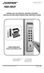
Step 4c cont’dHot (Bla c k )Line120 V A C , 60H zNOTE: The dimmer must be installed in a wall box that has a Loadconnection. The matching remote must be installed in a wall box witha Line Hot connection and a Neutral connection. A Neutral wire to thematching remote needs to be added as shown.If you are unsure about any part of these instructions, consult aqualified electrician.NOTE: Maximum wire length from dimmer to all installed remotescannot exceed 300 ft (90 m).Wiring Matching Remote (wall box with line hotconnection):Connect wires per WIRING DIAGRAM as follows:• Green or bare copper wire in wall box to Green terminal screw.• Line Hot (common) wall box wire identified (tagged) when removingold switch and First Traveler to Remote terminal marked BK.• Second Traveler wall box wire from dimmer to remote terminalscrew marked "YL/RD" (note wire color). This traveler from theremote must go to Yellow/Red dimmer lead.• Line Neutral wall box to remote terminal screw marked "WH".Wiring Dimmer (wall box with load connection):Connect wires per WIRING DIAGRAM as follows:• Green or bare copper wire in wall box to Green dimmer lead.• Load wall box wire identified (tagged) when removing old switch toRed dimmer lead.• First Traveler Line Hot to Black dimmer lead.• Remove Red insulating label from Yellow/Red dimmer lead.• Second Traveler wall box wire (note color as above) toYellow/Red dimmer lead. This traveler from the dimmer must go tothe terminal screw on the remote marked "YL/RD".• Line neutral wall box wire to White dimmer lead.• Proceed to Step 5.Step 5 Testing your Dimmer prior to mounting inwall box:• Position all wires to provide room in outletwall box for device.• Ensure that the word “TOP” isfacing up on device strap.• Partially screw in mounting screwsin wall box mounting holes.NOTE: Dress wires with a bend asshown in diagram in order to relievestress when mounting device.• Restore power at circuit breaker or fuse.• Press pad until locator light is OFF. Lights should turn ON. If lightsdo not turn ON, press the right half of the DIM/BRIGHT Bar until thelights brighten.If lights still do not turn ON, refer tothe TROUBLESHOOTING section.Step 6Mat c hing Remote (with LEDs )Neutral (White)WHBKGreenG r oun dYL/RDGreenGroundYellow/RedDimmerDimmer Mounting:TURN OFF POWER AT CIRCUITBREAKER OR FUSE.Installation may now be completed by tighteningmounting screws into wall box. Attach wallplate.BlackRedWhiteBlackWhiteBallastPrimarySideStep 7Step 8Note: If the dimmer has been successfully Included in the network andthe user tries to Include it again without first excluding it from the network,the dimmer will retain the first node ID ithad received and ignore the second.NOTE: Programmer/Controllermust be in close proximity to dimmerwhen including in the network.Step 9Restore Power:Restore power at circuit breaker or fuse.Installation is complete.Including Scene Capable Magnetic LowVoltage Dimmer into Z-Wave ® Network:NOTES:• If using a non-<strong>Leviton</strong> Programmer/Controller, refer to theProgrammer/Controller instruction sheet for Including a device.• If using VRCPG's install checklist go directly to step B.A) If using a <strong>Leviton</strong> Z-Wave ®Programmer/ControllerProgrammer/Controller, Cat. No. VRCPG, Cat. No. VRCPGpress the Menu button and scroll down to SystemSetup. Press the center button to select SystemSetup Menu. Choose Advanced Setting. Press thecenter button to select Network. Menu ButtonB) While standing close to the Center Buttondimmer (approximately 1 foot), press the centerbutton to device in the network.NOTE: Only one device may beincluded at a time. DO NOT put multipledevices into the Inclusion mode at any time.C) While the Programmer/Controller is in the Inclusionmode and the Locator LED is ON on the dimmer,press the push pad to turn on the dimmer. TheProgrammer/Controller will verify inclusion and theLocator LED will turn OFF.If the dimmer is flashing Amber while in the Inclusion mode, theProgrammer/Controller is still trying to communicate with the dimmer.Wait until the device stops flashing, then press the push pad.NOTE: If the Locator LED on the dimmer turns solid Red whileincluding, there has been a communication error. Refer toTroubleshooting section.D) The Primary Programmer/Controller will assign a node ID number(Name) for this device.NOTE: This ID number (Name) will be stored in the controller to beused for future reference.NOTE: You may edit the device name at this time.E) The dimmer is now installed in the network.Programmer/ControllerCat. No. VRCPGExcluding Dimmer from Z-Wave ® Network:NOTE: It is very important to accurately Exclude devices fromthe network when moving or removing a device from a Z-Wave ®network. This ensures that all information has been removed from yourPrimary Programmer/Controller's information table and is not counted onto be part of the mesh network.A) If using a <strong>Leviton</strong> Z-Wave ® Programmer/Controller, Cat. No. VRCPG,press the Menu button and scroll down to System Setup. Pressthe center button to select System Setup Menu. Choose AdvancedSetting. Press the center button to select Network.B) While standing close to the dimmer (approximately 1 foot), press thecenter button to device from the network.C) While the Programmer/Controller is in the Exclusion mode and thelocator LED is ON on the Dimmer, press the push pad to turn on theDimmer. The Programmer/Controller will verify Exclusion and thelocator LED will turn OFF.If the Dimmer is flashing Amber while in the Exclusion mode, theProgrammer/Controller is still trying to communicate with the Dimmer.Wait until the device stops flashing, then press the push pad.1 ON2 ON3 ON4 ONOFFOFFOFFOFFFactory Default:If your dimmer is not responding, or you are unable to control it afteryou have tried to Include/Exclude it multiple times, it may be necessaryto reset the dimmer to its original factory settings. To accomplish this,proceed as follows:• On the dimmer, engage the air-gap switch (refer to Operationsection) and wait 5 seconds. Press the push pad back into the frameand hold push pad until the locator LED turns Amber and then turnsRed. The dimmer is now reset. Once the dimmer is reset, it will benecessary to Re-Include it to a network before it can be used.CAUTION: SETTING A DEVICE TO A FACTORY DEFAULT DOESNOT EXCLUDE THAT DEVICE FROM A NETWORK. THE EXCLUSIONPROCEDURE MUST STILL BE FOLLOWED TO REMOVE THE DEVICEFROM THE PRIMARY CONTROLLER’S INFORMATION TABLE.FAILURE TO DO SO MAY RESULT IN SYSTEM THAT IS SLOW TORESPOND, OR MAY FAIL TO RESPOND TO SOME DEVICES.OPERATIONNOTE: The locator light will illuminate when the loadis in the OFF position to facilitate access in the dark.NOTE: If using the dimmer in a 3-wayapplication, thelights will turn ON at brightness set on dimmer’sDIM/BRIGHT bar. The lighting can be controlledfrom either the dimmer or the remote location.Push Pad (Default settings)Turn ON from OFF position:Tap – Lights turn ON to preset level.Press and Hold – Lights turn ON to full bright.Turn OFF from ON position:Tap – Lights turn OFF.DIM/BRIGHT BarBRIGHTEN:Press the right half of the DIM/BRIGHT Bar – Lights Pushbrighten to desired level.PadDIM:Press the left half of the DIM/BRIGHT Bar – Lights dim to desired level.If you continue to hold, the lights will DIM tominimum level and then turn OFF.NOTE: When lights are OFF you can change thelight level that the lights will turn ON to using theDIM/BRIGHT Bar.If there is a power outage, when the power isrestored, the lights will return to the last settingbefore the power interruption.ADVANCED PROGRAMMING FEATURESLED BrightnessDisplayDIM/BRIGHTBarLocatorLightGently press top ofpush padAir-Gap Switch: On the dimmer only, engage the airgapswitch by gently pressing the top of the push paduntil the bottom lifts completely out of the frame anda click is heard (refer to Figure). LED's will turn OFF.This will stop power to the fixture to replace the bulb.After servicing is complete, press the push pad backinto place for normal operation.Cleaning: Clean with a damp cloth. DO NOT use chemical cleaners.Definition of A ModesA-1) Energy Save: Sets the maximum brightness level for energy savings.A-2) Minimum Brightness Level: Sets the minimum dimming level.A-3) Preset ON Level: Sets the turn on brightness level regardless of theprevious set light level (formerly Dim Lock).Definition of B ModesB-1) ON Fade Rate: Sets the amount of time in seconds it takes thelights to turn ON to maximum brightness.B-2) OFF Fade Rate: Sets the amount of time in seconds it takes thelights to turn OFF from maximum brightness.B-3) LED Options: Sets the time period in seconds the Locator LED andBrightness display will stay on before extinguishing.Definition of LEDsLeftmost LED = LED 1Rightmost LED = LED 7NOTES:• The device will exit programming modeafter 3 minutes of inactivity.• Pressing the push pad at any timeduring programming will advance thedevice to the next programming mode.Program Mode ATo enter Program Mode A:Press and hold the Push Pad and then the right half of theDIM/BRIGHT Bar (^) for 5 seconds until the Locator LED and leftmostLED (LED 1) begin to blink.A-1) Upon releasing the Push Pad and the right half of the DIM/BRIGHTBar (^), the Locator LED will continue to blink once per secondand the rightmost LED will illuminate to display the device is inProgram Mode A-1, Energy Save. The default energy save modeis 100% i.e. full bright. To change the Energy Save level, use theDIM/BRIGHT Bar to move the corresponding LED to the desireddiscrete preset level according to Chart A. By tapping the PushPad this setting will automatically be saved and the device willadvance to the next programming mode, A-2.When indicatorlight is at LED #7654321Chart ALight output is at100%97%95%90%85%80%75%1 2 3 4 5 6 7LED BrightnessDisplayEnergy consumptionsavings amounts to0%5%8%11%14%17%20%A-2) The Locator LED will blink 2 times per second to indicate the deviceis in Program Mode A-2, Minimum Brightness Level. The defaultMinimum Brightness Level is LED 2. To change the MinimumBrightness Level from 1-50%, use the DIM/BRIGHT Bar. The lightoutput will reflect the minimum brightness level selected. By tappingthe Push Pad this setting will automatically be saved and the devicewill advance to the next programming mode, A-3.A-3) The Locator LED will blink 3 times per second to indicate ProgramMode A-3, Preset ON Level. To change the current Preset ONLevel from 1-100%, use the DIM/BRIGHT Bar. If this feature is notdesired, press and hold the left half of the DIM/BRIGHT Bar (v) untilno LED is lit (default setting). By tapping the Push Pad this setting willautomatically be saved and the device will exit Programming Mode A.Program Mode BTo enter Program Mode B:Press and hold the Push Pad and then the left half of theDIM/BRIGHT Bar (v) for 5 seconds until the Locator LED and rightmostLED (LED 7) begin to blink.B-1) Upon releasing the Push Pad and the left half of theDIM/BRIGHT Bar (v), the Locator LED will continue to blink onceper second indicating the dimmer is in Program Mode B-1, ON FadeRate. To change the ON Fade Rate, use the DIM/BRIGHT Bar tomove the LED to the desired preset level according to Chart B. Bytapping the Push Pad this setting will automatically be saved and thedevice will advance to the next programming mode, B-2.B-2) The Locator LED will blink 2 times per second to indicate ProgramMode B-2, OFF Fade Rate. To change the OFF Fade Rate, usethe DIM/BRIGHT Bar to move the LED to the desired preset levelaccording to Chart B. By tapping the Push Pad this setting willautomatically be saved and the device will advance to the nextprogramming mode, B-3.LEDLED <strong>1L</strong>ED 2 (Default)LED 3LED 4LED 5LED 6LED 7B-3) The Locator LED will blink 3 times per second to indicateProgram Mode B-3, LED Options. To change the LED Optionssettings, use the DIM/BRIGHT Bar to move the LED to thedesired preset setting according to the Chart B-3. By tappingthe Push Pad this setting will automatically be saved and thedevice will exit Programming Mode B.LEDLED <strong>1L</strong>ED 2LED 3LED 4LED 5LED 6LED 7TROUBLESHOOTINGChart BFADE ON0 seconds (instant)0.5 seconds1.5 seconds3.0 seconds6.0 seconds10 seconds25 seconds• Lights Flickering- Lamp has a bad connection.- Wires not secured firmly with wire connectors of dimmer orterminal screws of remote.• Light does not turn ON and Locator LED does not turn ON- Circuit breaker or fuse has tripped.- Lamp is burned out.- Neutral not wired to Dimmer (White wire).- Confirm that the device is being supplied from a 120V, 60 Hz ACsource ONLY.- Confirm that unit is programmed properly. Repeat "TO INSTALL"section to verify that it has been included in the Z-Wave ® network.• I ntermittent dimmer operation- Minimum load is under 40W.- Confirm that the Load being controlled does not exceed the1000VA dimmer limit.• Remote does not operate lights- Ensure that total wire length does not exceed 300 ft.- Ensure wiring is correct.For additional information, contact <strong>Leviton</strong>’s Techlineat 1-800-824-3005 or visit <strong>Leviton</strong>’swebsite at www.ViziaRF+.comProtected under U.S. Patent Number 6,388,399 and patents pendingand licensed under U.S. Patents Numbers 5,905,442, and 5,982,103FCC COMPLIANCE STATEMENTFADE OFF0 seconds (instant)0.5 seconds1.5 seconds3.0 seconds6.0 seconds10 seconds25 secondsChart B-3LOCATOR LED TIMEOUT LED BRIGHTNESS DISPLAY OPTIONSActiveActiveActiveTurns off 5 sec. after useTurns off 5 sec. after use ActiveTurns off 5 sec. after use Turns off 5 sec. after useActiveLED Bar activeActiveLED Bar turns off 5 sec. after useTurns off 5 sec. after use LED Bar turns off 5 sec. after useThis equipment has been tested and found to comply with the limits for a Class BDigital Device, pursuant to Part 15 of the FCC Rules. These limits are designedto provide reasonable protection against harmful interference in a residentialinstallation. This equipment generates, uses, and can radiate radio frequencyenergy and, if not installed and used in accordance with the instructions, maycause harmful interference to radio communications. However, there is noguarantee that interference will not occur in a particular installation. If thisequipment does cause harmful interference to radio or television reception, whichcan be determined by turning the equipment OFF and ON, the user is encouragedto try to correct the interference by one or more of the following measures:• Reorient or relocate the receiving Antenna.• Increase the separation between the equipment and the receiver.• Connect the equipment into an outlet on a circuit different from thatto which the receiver is connected.• Consult the dealer or an experienced radio/tv technician for help.DI-000-<strong>VRM10</strong>-02ALIMITED 5 YEAR WARRANTY AND EXCLUSIONS<strong>Leviton</strong> warrants to the original consumer purchaser and not for the benefit of anyone else that this product at the time of its sale by <strong>Leviton</strong> is free of defects in materials and workmanship under normal and proper use for five years from the purchase date. <strong>Leviton</strong>’s only obligation is to correct such defects by repair or replacement, at its option, if within such five year period the product is returned prepaid, with proofof purchase date, and a description of the problem to <strong>Leviton</strong> Manufacturing Co., Inc., Att: Quality Assurance Department, 59-25 Little Neck Parkway, Little Neck, New York 11362-2591. This warranty excludes and there is disclaimed liability for labor for removal of this product or reinstallation. This warranty is void if this product is installed improperly or in an improper environment, overloaded, misused,opened, abused, or altered in any manner, or is not used under normal operating conditions or not in accordance with any labels or instructions. There are no other or implied warranties of any kind, including merchantability and fitness for a particular purpose, but if any implied warranty is required by the applicable jurisdiction, the duration of any such implied warranty, including merchantability and fitnessfor a particular purpose, is limited to five years. <strong>Leviton</strong> is not liable for incidental, indirect, special, or consequential damages, including without limitation, damage to, or loss of use of, any equipment, lost sales or profits or delay or failure to perform this warranty obligation. The remedies provided herein are the exclusive remedies under this warranty, whether based on contract, tort or otherwise.