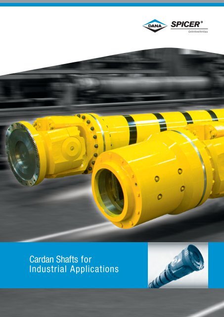
Cardan Shafts for Industrial Applications
Cardan Shafts for Industrial Applications
Cardan Shafts for Industrial Applications
- No tags were found...

You also want an ePaper? Increase the reach of your titles
YUMPU automatically turns print PDFs into web optimized ePapers that Google loves.
Table of Contents1 Dana: Driveshaft engineering experts4 Survey of Spicer ® GWB TM cardanshaft series with design featuresand preferred applications8 Special designs of Spicer ® GWB TM cardanshafts and additional equipment10 Notations <strong>for</strong> reviewing data sheetsData sheets12 Series 687/68816 Series 58718 Series 39020 Series 392/39322 Series 49224 Series 49826 Series 587/190 Super short designs28 Series 330 Quick release couplings29 Series 230 Quick release couplings30 Journal cross assemblies31 Flange connection with serration32 Face key connectionseries 687/688/587/39033 Standard companion flanges34 Design features Series 687/688/587and series 390/392/39336 General theoretical instructions38 Technical instructions <strong>for</strong> application48 Selection of Spicer ® GWB TM cardan shafts51 Additional in<strong>for</strong>mation and orderinginstructions52 After-sales service
Dana: Driveshaft engineering experts For more than100 years, Dana’s expertise and worldwide network of manufacturingpartnerships have sustained its ability to supply economicallyefficient, high-per<strong>for</strong>mance products to original equipmentmanufacturers (OEMs) in changing market environments.With a focus on technical innovation,quality per<strong>for</strong>mance, reliability,and flexibility, Dana engineerscontinue to provide customerswith the same quality and supportthey’ve come to expect.Since 1946, Dana’s Spicer ® GWB TMcardan shafts have been known<strong>for</strong> global innovation and qualityper<strong>for</strong>mance. SPICER ® GWB TMheavy cardan shafts were the firstto be developed specifically <strong>for</strong>diesel locomotives. In the 1950s,Spicer ® GWB TM cardan shaftswere the largest available at thattime, and were followed severaldecades later by the first maintenance-freecardan shaft. Basedon a long-standing commitmentto continual innovation and customersatisfaction, SPICER ® GWB TMcardan shafts have been recognizedas a market leader troughoutthe world.SPICER ® GWB TM cardan shaftsinclude a wide range of products<strong>for</strong> multiple applications, coveringa torque range from 2.400 to15.000.000 Nm.1
Survey of Spicer ® GWB TM cardan shaft seriesSeries687/688Torque range T CSfrom 2,4 to 35 kNmFlange diameterfrom 100 to 225 mm587Torque range T CSfrom 43 to 57 kNmFlange diameterfrom 225 to 285 mm390Maximum bearing lifeTorque range T CSfrom 60 to 255 kNmFlange diameterfrom 285 to 435 mm4
Survey of Spicer ® GWB TM cardan shaft seriesDesign featuresPreferred applications• Closed bearing eyes• Compact design• Low maintenance• Plastic-coated splines• Operating angle up to 25°, partly up to 44°• Railway vehicles• Rolling mill plants• Marine drives• General machinery construction plantsTechnical data (refer to data sheets)• Closed bearing eyes• Compact design• Low maintenance• Splines coated with lubricating varnish(587.50 – plastic-coated)• Operating angle up to 24°• Railway vehicles• Rolling mill plants• Marine drives• General machinery construction plantsTechnical data (refer to data sheets)• Maximum bearing life in confined spaces• Split bearing eyes with toothed bearing cap• Compact design• Optimized roller bearing• Length compensation coated with lubricatingvarnish• Operating angle up to 15°• Railway vehicles• Marine drives• Crane systems• Paper machines• General machinery construction plantsTechnical data (refer to data sheets)5
Survey of Spicer ® GWB TM cardan shaft seriesDesign featuresPreferred applications• High torque capacity despite small connectingdimensions• Split bearing eyes with toothed bearing cap• Compact design• Journal cross with low notch factor• Length compensation coated with lubricatingvarnish• Operating angle 10° up to 15°• Series 393 with optimized bearing life• Rolling mill plants• Calender drives• Heavy-loaded plants of general machineryconstructionTechnical data (refer to data sheets)• Increased torque capacity in comparison to 393• Split bearing eyes with toothed bearing cap• Standard Hirth-serrated flange• Journal cross with low notch factor• Length compensation coated with lubricantvarnish• Operating angle 7° up to 15°• Rolling mill plants• Calender drives• Extremely high loaded plants of generalmachinery constructionTechnical data (refer to data sheets)• Three operating angle versions <strong>for</strong> maximumtorque or maximum bearing life capacity• Split bearing eyes with toothed bearing cap• Standard Hirth-serrated flange• Operating angle up to 15°• Main rolling mill drive units• Heavy machinery construction plantsTechnical data (refer to data sheets)7
Special designs of Spicer ® GWB TM cardan shaftsand additional equipmentSeries587/190 Super short designsTorque range T CSfrom 23 to 94 kNmFlange diameterfrom 275 to 405 mm392/393 Tunnel joint shaftsTorque range T CSfrom 57 to 1.053 kNmFlange diameterfrom 225/315 to550/710 mmIntermediate shafts8
Special designs of Spicer ® GWB TM cardan shaftsand additional equipmentDesign featuresPreferred applications• Closed bearing eyes (series 587)• Split bearing eyes (series 190)• Joints and length compensationare regreasable• Operating angle up to 5°• Railway vehicles• Rolling mill plants• Marine drives• Calender drives• Paper machines• General machinery construction plantsTechnical data (refer to data sheets)• Shorter designs with large length compensation• Length compensation through the joint• High torque capacity with small connectiondimensions• Split bearing eyes with toothed bearing cap• Bearings with labyrinth seals• Operating angle up to 10°/ 7,5°• Rolling mill plants• With or without length compensation• Integrated bearing location• Pump drives9
Notations <strong>for</strong> reviewing data sheetsStandard designs0.01<strong>Cardan</strong> shaft with lengthcompensation, tubular design0.03<strong>Cardan</strong> shaft without lengthcompensation, tubular design9.019.029.03<strong>Cardan</strong> shaft with lengthcompensation, short design9.04<strong>Cardan</strong> shaft without lengthcompensation, double flangeshaft designSpecial designs0.02<strong>Cardan</strong> shaft with large lengthcompensation, tubular design9.06<strong>Cardan</strong> shaft with lengthcompensation, super shortdesign10
Data sheet series 687/6880.02 with length compensation, tubular design0.03 without length compensation, tubular design9.01 with length compensation, short design9.03 with length compensation, short design9.04 without length compensation, double flangeshaft designDesignML zMG∅W∅S∅KF∅A∅C0.02Shaft size 687/688.15 687/688.20 687/688.25 687/688.30 687/688.35 687/688.40T CS kNm 2,4 3,5 5 6,5 10 14T DW kNm 0,7 1,0 1,6 1,9 2,9 4,4Lc – 1,79 x 10 –4 5,39 x 10 –4 1,79 x 10 –3 2,59 x 10 –3 0,0128 0,0422b
Data sheet series 687/688DesignL f60°22,5°0.0345°L z∅B∅B9.019.03L f∅H6-hole flange∅H8-hole flangeNOTE: Hole patterns are not optional.Each cardan shaft size has a specific hole pattern.9.04Design Shaft size 687/688.15 687/688.20 687/688.25 687/688.30 687/688.35 687/688.400.020.039.019.039.04L z min mm 346 379 458 492 504 582 572 586 693 586 693L a mm 60 70 100 110 110 110 110 110 180 110 180G kg 5,7 8,4 12,0 13 14,2 24,0 25,6 28,7 30,3 29,4 30,9G R kg 3,62 4,37 5,13 6,44 6,44 7,18 7,18 8,66 10,6 8,66 10,6Jm kgm 2 0,0043 0,0089 0,0144 0,0245 0,0245 0,043 - 0,0676 0,0706 0,0776 0,0806Jm R kgm 2 0,0034 0,0059 0,0096 0,0122 0,0122 0,0169 0,0169 0,0296 0,0242 0,0296 0,0242C Nm/rad. 0,26 x 10 5 0,42 x 10 5 0,71 x 10 5 0,78 x 10 5 0,78 x 10 5 1,18 x 10 5 - 2,17 x 10 5 1,61 x 10 5 2,17 x 10 5 1,61 x 10 5C R Nm/rad. 0,34 x 10 5 0,60 x 10 5 0,98 x 10 5 1,25 x 10 5 1,25 x 10 5 1,72 x 10 5 1,72 x 10 5 3,02 x 10 5 2,47 x 10 5 3,02 x 10 5 2,47 x 10 5L f min mm 221 239 282 310 322 379 369 423 449 423 449G kg 4,1 5,8 8,6 8,6 9,8 18,0 19,6 22,8 21,0 23,4 21,6Jm kgm 2 0,0038 0,0085 0,0129 0,0238 0,0238 0,04 - 0,066 0,0628 0,076 0,0728C Nm/rad. 0,44 x 10 5 0,86 x 10 5 1,44 x 10 5 1,74 x 10 5 1,74 x 10 5 1,81 x 10 5 - 3,35 x 10 5 2,78 x 10 5 3,35 x 10 5 2,78 x 10 5L z min mm 296 322 361 379 391 510 500 505 525 505 525L a min mm 38 41 36 36 36 70 70 70 60 70 60L z max mm 348 381 425 453 465 550 540 545 645 545 645L a max mm 90 100 100 110 110 110 110 110 180 110 180L z min mm 245 274 313 331 343 419 409 441 – 441 –L a min mm 25 27 28 29 29 45 45 45 – 45 –L z max mm 280 317 355 397 409 484 474 506 – 506 –L a max mm 60 70 70 95 95 110 110 110 – 110 –L f min mm 192 216 280 288 312 380 360 408 408 408 408L z min = Shortest possible compressed lengthL a = Length compensationL f min = Shortest fi xed lengthL z + L a = Maximum operating lengthGG RJmJm R= Weight of shaft= Weight per 1.000 mm tube= Moment of inertia= Moment of inertia per 1.000 mm tubeCC R= Torsional stiffness of shaft without tube= Torsional stiffness per 1.000 mm tube13
Data sheet series 687/6880.02 with length compensation, tubular design0.03 without length compensation, tubular design9.01 with length compensation, short design9.03 with length compensation, short design9.04 without length compensation, double flangeshaft designDesignML zMG∅W∅S∅KF∅A∅Cb0.02Shaft sizeT CSkNmT DWkNmLc –b
Data sheet series 687/688DesignL f22,5°36°0.0345°L z∅B∅B9.019.03∅H8-hole flange∅H10-hole flangeL fNOTE: Hole patterns not optional.Each cardan shaft size has a specific hole pattern.9.04Design Shaft size 687/688.45 687/688.55 687/688.650.020.039.019.039.04L z min mm 595 703 585 662 681 622 686 686L a mm 110 180 110 110 110 110 110 110G kg 35,7 38,4 37,7 44,0 49,2 47,0 60,6 64,6G R kg 11,44 12,95 11,44 16,86 16,86 16,86 20,12 20,12Jm kgm 2 0,1002 0,1242 0,1342 0,131 – 0,151 0,2224 0,2614Jm R kgm 2 0,0385 0,0357 0,0385 0,055 – 0,055 0,0932 0,0932C Nm/rad. 3,10 x 10 5 2,18 x 10 5 3,10 x 10 5 4,05 x 10 5 – 4,05 x 10 5 5,63 x 10 5 5,63 x 10 5C R Nm/rad. 3,93 x 10 5 3,65 x 10 5 3,93 x 10 5 5,60 x 10 5 5,60 x 10 5 5,60 x 10 5 9,50 x 10 5 9,50 x 10 5L f min mm 425 425 415 475 495 435 491 491G kg 28,0 27,8 30 33,1 – 36,1 47,3 51,3Jm kgm 2 0,0954 0,0976 0,1294 0,1176 – 0,1376 0,2032 0,2422C Nm/rad. 4,82 x 10 5 3,71 x 10 5 4,82 x 10 5 5,39 x 10 5 – 5,39 x 10 5 7,17 x 10 5 7,17 x 10 5L z min mm 517 538 507 587 606 547 601 601L a min mm 70 60 70 70 70 70 70 70L z max mm 557 658 547 617 636 577 641 641L a max mm 110 180 110 100 100 100 110 110L z min mm 447 – 437 513 – 473 524 524L a min mm 50 – 50 50 – 50 50 50L z max mm 507 – 497 563 – 523 584 584L a max mm 110 – 110 110 – 110 110 110L f min mm 380 380 360 460 460 380 440 440L z min = Shortest possible compressed lengthL a = Length compensationL f min = Shortest fi xed lengthL z + L a = Maximum operating lengthGG RJmJm R= Weight of shaft= Weight per 1.000 mm tube= Moment of inertia= Moment of inertia per 1.000 mm tubeCC R= Torsional stiffness of shaft without tube= Torsional stiffness per 1.000 mm tube15
Data sheet series 587DesignL fStandard flange connection38°22,5°22,5°0.0345°45°48°L z9.019.029.03∅B∅B s∅BL f∅H∅H∅Hs9.048-hole flange8-hole flangeDowel pin connection according to DIN 15451Design Shaft size 587.50 587.55 587.600.010.02*L z min mm – – 840 840 870L a mm – – 100 100 100G kg – – 118 123 132G R kg – – 29,1 29,1 38,2Jm kgm 2 – – 0,657 0,737 0,950Jm R kgm 2 – – 0,190 0,190 0,239C Nm/rad. – – 8,7 x 10 5 8,7 x 10 5 9,6 x 10 5C R Nm/rad. – – 19,4 x 10 5 19,4 x 10 5 24,3 x 10 5L z min mm 800 800 960 960 990L a min mm 110 110 200 200 200G kg 86 91 155 160 170G R kg 23,7 23,7 29,1 29,1 38,2Jm kgm 2 0,325 0,361 - - -Jm R kgm 2 0,111 0,111 0,190 0,190 0,2390.039.019.029.039.04C Nm/rad. 5,29 x 10 5 5,29 x 10 5 - - -C R Nm/rad. 11,33 x 10 5 11,33 x 10 5 19,4 x 10 5 19,4 x 10 5 24,3 x 10 5L f mm 540 540 610 610 640G kg 72 77 88 93 103G R kg 23,7 23,7 29,1 29,1 38,2Jm kgm 2 0,270 0,306 0,547 0,627 0,84Jm R kgm 2 0,111 0,111 0,190 0,190 0,239C Nm/rad. 7,2 x 10 5 7,2 x 10 5 9,8 x 10 5 9,8 x 10 5 11,5 x 10 5C R Nm/rad. 11,33 x 10 5 11,33 x 10 5 19,4 x 10 5 19,4 x 10 5 24,3 x 10 5L z min mm – – 815 815 843L a mm – – 100 100 100G kg – – 110 115 142Jm kgm 2 – – 0,64 0,72 0,93C Nm/rad. – – 8,8 x 10 5 8,8 x 10 5 9,7 x 10 5L z mm – – 780 780 810L a mm – – 65 65 70G kg – – 108 113 125L z mm 550 600 650 696 550 600 650 696 720 720 750L a mm 60 75 90 110 60 75 90 110 65 65 65G kg 61 66 68 70 66 71 73 75 113 118 126L f mm 432 432 500 500 540G kg 58 68 81 91 110L z min = Shortest possible compressed lengthL a = Length compensationL f min = Shortest fi xed lengthL z + L a = Maximum operating lengthGG RJmJm R= Weight of shaft= Weight per 1.000 mm tube= Moment of inertia= Moment of inertia per 1.000 mm tubeC = Torsional stiffness of shaft without tubeC R = Torsional stiffness per 1.000 mm tube* Larger length compensation available on request17
Data sheet series 390 Maximum bearing lifeDesignL zL z0.029.019.029.03L fL f0.03 9.04Standardflangeconnection38°22,5°45°18°36°Dowel pin connectionaccordingto DIN 1545122,5°45°48°18°36°36°∅B∅B∅B s∅B∅B s∅B∅H∅H∅H∅Hs∅H∅Hs8-hole flange10-hole flange8-hole flange10-hole flangeNOTE: Each cardan shaft size has a specific holepattern (see table). Other hole patterns available on request.Design Shaft size 390.60 390.65 390.70 390.75 390.800.010.02*0.039.019.029.039.04L z min mm 870 980 1.070 1.210 1.280L a mm 100 135 135 170 170G kg 138 216 276 405 490G R kg 38,2 45,0 67,5 74,8 119Jm kgm 2 1,04 1,61 2,51 4,20 8,20Jm R kgm 2 0,239 0,494 0,716 1,28 1,93C Nm/rad. 1,0 x 10 6 1,65 x 10 6 2,43 x 10 6 3,3 x 10 6 4,7 x 10 6C R Nm/rad. 2,43 x 10 6 5,04 x 10 6 7,3 x 10 6 1,3 x 10 7 1,96 x 10 7L z min mm 990 1.080 1.170 1.295 1.365L a min mm 200 220 220 250 250G kg 178 280 337 508 586G R kg 38,2 45,0 67,5 74,8 119L f min mm 640 710 800 890 960G kg 109 159 218 302 385G R kg 38,2 45,0 67,5 74,8 119L z mm 843 953 1.043 1.175 1.245L a mm 100 135 135 170 170G kg 136 213 273 402 482L z mm 810 890 980 1.100 1.170L a mm 70 75 75 95 95G kg 135 198 261 375 456L z mm 750 835 925 1.030 1.100L a mm 65 75 75 85 85G kg 135 202 264 371 453L f mm 540 600 680 760 840G kg 108 146 210 284 380L z min = Shortest possible compressed lengthL a = Length compensationL f min = Shortest fi xed lengthL z + L a = Maximum operating lengthGG RJmJm R= Weight of shaft= Weight per 1.000 mm tube= Moment of inertia= Moment of inertia per 1.000 mm tubeC = Torsional stiffness of shaft without tubeC R = Torsional stiffness per 1.000 mm tube* Larger length compensation available on request19
Data sheet series 392/393 High torque capacity0.01 with length compensation, tubular design0.02 with large length compensation, tubular design0.03 without length compensation, tubular design9.01 with length compensation, short design9.02 with length compensation, short design9.03 with length compensation, short design9.04 without length compensation, double flangeshaft designDesignML zMG∅A∅C∅W∅S∅KFbX0.01YShaft sizeT CSkNmT DWkNmLc –b
Data sheet series 392/393 High torque capacityDesignL z0.02L f38°22,5°45°Flange connection with face key15°30°10°20°0.03∅B∅B∅BL z9.019.029.03∅H8-hole flange∅H10-hole flange∅H16-hole flange9.04L fEach cardan shaft size has a specifichole pattern (see table). Otherhole patterns available on request.Design Shaft size 392.50 392.55 392.60 392.65 392.70 393.75 393.80 393.85 393.900.010.02*0.039.019.029.039.04L z min mm 890 1.010 1.090 1.240 1.310 1.430 1.620 1.820 2.035L a mm 100 135 135 170 170 170 170 190 210G kg 129 214 272 406 493 732 1.055 1.468 2.209G R kg 38,2 45 67,5 74,8 119 210,4 255,6 311,3 401,1Jm kgm 2 1,02 1,43 2,23 3,80 6,5 11,72 17,84 25,21 40,76Jm R kgm 2 0,239 0,494 0,716 1,28 1,93 3,02 5,38 7,87 13,3C Nm/rad. 9,5 x 10 5 1,42 x 10 6 2,36 x 10 6 3,1 x 10 6 4,4 x 10 6 5,19 x 10 6 7,86 x 10 6 9,44 x 10 6 1,43 x 10 7C R Nm/rad. 2,43 x 10 6 5,06 x 10 6 7,3 x 10 6 1,3 x 10 7 1,96 x 10 7 3,08 x 10 7 5,48 x 10 7 8,03 x 10 7 1,36 x 10 8L z min mm 1.010 1.110 1.190 1.325 1.395 1.570 1.780 1.975 2.190L a min mm 200 220 220 250 250 310 330 345 365G kg 171 275 331 515 603 796 1.158 1.589 2.367G R kg 38,2 45 67,5 74,8 119 210,4 255,6 311,3 401,1L f min mm 660 740 820 920 990 977 1.110 1.240 1.380G kg 101 156 215 301 389 538 748 1.052 1.600G R kg 38,2 45 67,5 74,8 119 210,4 255,6 311,3 401,1L z mm 863 983 1.063 1.205 1.275 1.363 1.550 1.750 1.955L a mm 100 135 135 170 170 170 170 190 210G kg 130 210 269 402 487 718 1.037 1.446 2.177L z mm 830 920 1.000 1.130 1.200 1.300 1.400 1.630 1.770L a mm 70 75 75 95 95 90 90 100 100G kg 124 204 263 375 466 641 876 1.171 1.717L z mm 770 865 945 1.060 1.130 1.200 1.300 1.520 1.680L a mm 65 75 75 85 85 70 70 80 80G kg 123 197 260 371 457 602 832 1.116 1.657L f mm 580 660 720 820 900 820 940 1.060 1.160G kg 94 145 207 288 391 485 653 922 1.443L z min = Shortest possible compressed lengthL a = Length compensationL f min = Shortest fi xed lengthL z + L a = Maximum operating lengthGG RJmJm R= Weight of shaft= Weight per 1.000 mm tube= Moment of inertia= Moment of inertia per 1.000 mm tubeC = Torsional stiffness of shaft without tubeC R = Torsional stiffness per 1.000 mm tube* Larger length compensation available on request21
Data sheet series 492 Maximum torque capacity0.01 with length compensation, tubular design0.03 without length compensation, tubular design9.01 with length compensation, short design9.02 with length compensation, short design9.03 with length compensation, short design9.04 without length compensation, double flangeshaft designDesignGM∅WL z∅A∅S∅KM0.01Shaft size 492.60 492.65 492.70 492.75 492.80 492.85 492.90T CS kNm 210 250 340 440 410 650 580 850 770 1.300 1.170T DW kNm 100 115 160 210 190 280 250 400 360 600 540Lc – 107 332 860 2.060 7.390 17.400 60.120b
Data sheet series 492 Maximum torque capacityDesignL fFlange connection with Hirth-serration36°30°22,5°0.03L z∅B∅B∅B9.019.029.03∅H∅H∅HL f10-hole flange12-hole flange16-hole flange9.04Each cardan shaft size has a specifichole pattern (see table). Otherhole patterns available on request.Design Shaft size 492.60 492.65 492.70 492.75 492.80 492.85 492.900.010.039.019.04L z min mm 1.440 1.520 1.680 1.750 1.900 2.130 2.415L a mm 135 135 150 170 170 190 210G kg 472 568 788 1.025 1.355 1.873 2.750G R kg 121 149 180 255,6 311,3 361,4 501,94Jm kgm 2 4,16 5,16 7,73 15 30,7 50,4 92,7Jm R kgm 2 1,52 1,78 2,69 5,38 7,88 12,28 21,1C Nm/rad. 3,32 x 10 6 4,31 x 10 6 5,97 x 10 6 6,76 x 10 6 9,7 x 10 6 13,64 x 10 6 19,44 x 10 6C R Nm/rad. 1,55 x 10 7 1,82 x 10 7 2,75 x 10 7 5,48 x 10 7 8,03 x 10 7 12,51 x 10 7 21,5 x 10 7L f min mm 940 1.020 1.130 1.220 1.320 1.450 1.620G kg 311 407 557 819 1.040 1.330 1.880G R kg 121 149 180 255,6 311,3 361,4 501,9L z mm 1.380 1.460 1.620 1.700 1.840 2.050 2.340L a mm 135 135 150 170 170 190 210G kg 465 559 777 1.010 1.340 1.850 2.710L f mm 800 880 960 1.040 1.120 1.200 1.320G kg 286 374 514 780 1.000 1.300 1.830L z min = Shortest possible compressed lengthL a = Length compensationL f min = Shortest fi xed lengthL z + L a = Maximum operating lengthGG RJmJm R= Weight of shaft= Weight per 1.000 mm tube= Moment of inertia= Moment of inertia per 1.000 mm tubeCC R= Torsional stiffness of shaft without tube= Torsional stiffness per 1.000 mm tubeLength dimensions (L z /L a ) of the designs 0.02 · 9.02 · 9.03 available on request.23
Data sheet series 498DesignL fFlange connection with Hirth-serration18°15°0.03L f∅B∅B9.04∅H20-hole flange∅H24-hole flangeEach cardan shaft size has a specifichole pattern (see table). Otherhole patterns available on request.Shaft size 498.40 498.45 498.50 498.55 498.60T CS kNm 8.700 7.500 6.500 10.000 8.700 7.500 11.500 10.000 8.600 13.200 11.400 9.900 15.000 13.000 11.200T DW kNm 4.200 3.600 3.100 4.800 4.200 3.600 5.500 4.800 4.100 6.300 5.500 4.700 7.200 6.200 5.400Lc – 16,1 17,4 23,78 24,4 28,71 38,73 36,4 42,63 61,67 56,3 70,8 96,19 89,9 102 147,2x 10 6 x 10 6 x 10 6 x 10 6 x 10 6 x 10 6 x 10 6 x 10 6 x 10 6 x 10 6 x 10 6 x 10 6 x 10 6 x 10 6 x 10 6b
Data sheet series 587/190 Super short designs9.06 cardan shaft with length compensation,super short designSeries 587DesignML zM36°G∅B∅A∅C∅W∅KF36°b9.06∅H10-hole flangeShaft size 587.50 190.55 190.60 190.65 190.70T CS kNm 23 33 48 68 94T DW kNm 8,5 11 21 25 36Lc – 1,84 7,0 58,5 166 510b
Data sheet series 587/190 Super short designsSeries 190DesignML zM36°G∅A∅C∅W∅KF∅Bb36°9.06∅H10-hole flangeDesign Shaft size 587.50 190.55 190.60 190.65 190.709.06 L z mm 415 495 545 600 688L a mm 40 40 40 40 55G kg 60 98 120 169 256Jm kgm 2 0,33 0,624 1,179 2,286 3,785L z = Shortest compressed lengthL a = Length compensationL z + L a = Maximum operating lengthGJm= Weight of shaft= Moment of inertia27
Data sheet series 330 Quick release couplingsDesignwith spiral serration <strong>for</strong> higher speedsGF kLSW∅A∅B∅CKF∅CkConnection <strong>for</strong> series 687/688Connection <strong>for</strong> series 587Connection <strong>for</strong> series 392with face keyFor hole distribution, see datasheets of the correspondingcardan shaft.DCoupling size 330.10 330.20 330.30 330.40 330.50 330.55Shaft connection687/688.25 687/688.30 687/688.40 687/688.55687/688.15 687/688.20 687/688.45 587.50 392.50 587.55 392.55687/688.35 687/688.40 687/688.45 687/688.65Model Nr. 000 003 003 003 000 001 000 001A mm 100 130 150 180 225 225 250 250B mm 84 101,5 130 155,5 196 196 218 218C 1 ) mm 57 75 90 110 140 105 140 105C 11 k ) mm 57 75 90 110 140 105 140 105D 2 ) mm 20 38 40 40 45 45 45 45F mm 2,5 2,5 3,5 4 5 5 6 6F k mm 2,3–0,2 2,3–0,15 2,3–0,2 2,3–0,15 4–0,2 4–0,2 5–0,2 5–0,2G mm 76 100 100 112 144 144 148 162I 3 ) – 6 8 8 8 8 8 8 8K 4 ) – M 8 x 18 M 10 x 22 M 12 x 25 M 14 x 28 M 16 x 35 M 16 x 40 M 18 x 40 M 18 x 45L 10 ) mm 10 11 14 20 18 18 21 21G 12 k ) kg 4,7 7,5 10,6 16,4 34 36 40 49Ta Nut Nm 35 69 120 190 295 295 405 405Extension 5 ) Nr. 2.365/13 M 2.365/17 M 2.365/19 M 22 M 24 R 24 R 27 R 27 RTa Spindle Nm 30 45 80 100 190 190 220 220Socket wrench 6 )Nr.1 / 2“ D 19 SW 131 / 2“ D 19 SW 171 / 2“ D 19 SW 22Operating instructionsEngaging and disengaging the couplingEngaging and disengaging are done by operating the threadedspindle located in the inner part of the coupling. Thespindle can be reached from two sides and be operated. Thespindle is tightened by means of a socket wrench (see table).Notice:1. Be<strong>for</strong>e engaging the coupling, make sure that the couplingteeth are properly fitted.2. The engagement direction is marked by arrows. Thespindle may be tightened either clockwise or counterclockwise.3. The joint with the coupling component falls back whendisengaged. Caution: Danger of injury!In case of a subsequent installation of the quick releasecoupling, the cardan shaft must be correspondingly shorter.The threaded spindles of the coupling are lubricated by thesupplier with MoS 2 . Relubrication is recommended fromtime to time.28
Data sheet series 230 Quick release couplingsDesignwith trapezoidal serration <strong>for</strong> speeds up to 1000 rpmGF kKLFSWConnection <strong>for</strong> series 390Connection <strong>for</strong> series 392/393with face key∅A∅B∅C∅CkFor hole distribution, see datasheets of the correspondingcardan shaft.DCoupling size 230.60 230.65 230.70 230.75 230.80Shaft connection 390.60 392.60 390.65 392.65 390.70 392.70 390.75 393.75 390.80 393.80Model Nr. 000 001 000 001 000 001 000 001 000 001A mm 285 285 315 315 350 350 390 390 435 435B mm 245 245 280 280 310 310 345 345 385 385C 1 ) mm 175 125 175 130 220 155 250 170 280 190C 11 k ) mm 175 125 175 130 220 155 250 170 280 190D 2 ) mm 64 64 66 66 72 72 82 82 92 92F mm 7 7 7 8 8 8 8 8 10 10F k mm 6–0,2 6–0,5 6–0,2 7–0,5 7–0,3 7–0,5 7–0,2 7–0,5 9–0,5 9–0,5G mm 160 174 172 192 184 204 196 220 226 246I 3 ) – 8 8 8 10 10 10 10 10 10 16K 4 ) – M 20 x 55 M 20 x 55 M 22 x 50 M 22 x 60 M 22 x 50 M 22 x 60 M 24 x 55 M 24 x 70 M 27 x 65 M 27 x 75L 10 ) mm 23 23 25 25 25 25 27 27 30 30G 12 k ) kg 66 71 83 95 110 120 143 150 210 230Ta Nut Nm 580 580 780 780 780 780 1.000 1.000 1.500 1.500Extension 5 ) Nr. 30 R 30 R 32 R 32 R 32 R 32 R 36 R 36 R 41 R 41 RTa Spindle Nm 290 290 400 400 550 550 680 680 950 9 ) 950 9 )Socket wrench 6 )Nr.3 / 4“ D 32 SW 223 / 4“ D 32 SW 273 / 4“ D 32 SW 273 / 4“ D 32 SW 323 / 4“ D 32 SW 36X = 4 spanners 8 ) Nr. -TD 7501. Spigot fit H72. Disengaging movement <strong>for</strong> separation of the coupling3. Number of stud bolts per flange4. Dimensions of the bolt connectionsStud bolt DIN 938Self-locking hexagon nut DIN 9805. Jaw or ring extension in accordance with Dana standard N 4.2.56. Gedore socket spanner set <strong>for</strong> tightening the spindle7. Rahsol torque meter8. Force multiplier spanner x = 4 (TD 750)9. Adjusting moment of the torque wrench 756 C = 238 Nm10. Thread depth11. Fit h6 up to series 390Fit f8 <strong>for</strong> series 392/39312. Gk = Weight of couplingTa = Tightening torques of flange boltings and of thethreaded coupling spindlesTorque wrench 7 )Torque rangeTypefromto756 B20 Nm 100 Nm756 C80 Nm 300 Nm756 D280 Nm 760 NmFor applications with speeds higher than 1.000 rpm, please contact Danaengineers. Other designs available on request.29
Data sheet Journal cross assemblies (unit packs)Design7.06 journal cross, completeB∅A∅ ABShaft sizemmmm473.10 15 41473.20 19 49,2473.30 22 59287.00 26 69,8287.10 30 81,8287.20 35 96,8587.10 35 96,8587.15 42 104,5587.20 48 116,5587.30 52 133587.35/36 57 144587.42 57 152,06587.48 65 172587.50 72 185587.55 74 217587.60 83 231,4687/688.15 27,0 74,5687/688.20 30,2 81,8687/688.25 34,9 92,0687/688.30 34,9 106,4687/688.35 42,0 119,4687/688.40 47,6 135,17687/688.45 52,0 147,2687/688.55 57,0 152,0687/688.65 65,0 172,0B 1B∅AJournal cross assemblies are only supplied as completeunits. For orders, please state shaft size or, ifknown, the drawing number of the complete cardanshaft. For lubrication of journal cross assemblies,see Installation and Maintenance/Safety Instructions.* The dimensions of the journal cross assemblies<strong>for</strong> series 392/393 are equal to 292.Shaft size190.50 65 220 143190.55 74 244 154190.60 83 280 175190.65 95 308 190190.70 110 340 210190.75 120 379 235190.80 130 425 262390.60 83 235,8 129390.65 95 258,8 139390.70 110 293,4 160390.75 120 325,2 176390.80 130 363,2 196392.50* 74 222 129392.55* 83 246 139392.60* 95 279,6 160392.65* 110 309,6 176392.70* 120 343,4 196393.75* 130 383,4 216393.80* 154 430 250393.85* 170 464 276393.90* 195 530 315Ultra heavy-duty unit packsets <strong>for</strong> series 398 have beendiscontinued.∅ A B B 1mm mm mmThey are still available <strong>for</strong> series492 and 498 on request.30
Data sheet Flange connection with serrationHirth-serration• Flank angle 40°• High transmission capacity• Form locking• Self-centering∅D∅d∅BD d z B i*mm mm mm225 180 48 200 8 x M 12250 200 48 225 8 x M 14285 225 60 255 10 x M 14315 250 60 280 10 x M 16350 280 72 315 12 x M 16390 315 72 350 12 x M 18435 345 96 395 16 x M 18480 370 96 445 16 x M 20550 440 96 510 16 x M 22600 480 120 555 20 x M 24650 520 120 605 20 x M 24700 570 120 655 24 x M 24750 600 144 695 24 x M 30800 650 144 745 24 x M 30850 680 144 785 24 x M 36900 710 144 835 24 x M 36950 760 144 885 24 x M 361.000 800 180 925 20 x M 42 x 31.050 840 180 975 20 x M 42 x 31.100 880 180 1.025 20 x M 42 x 31.150 925 180 1.065 20 x M 48 x 31.200 960 180 1.115 20 x M 48 x 3Klingelnberg-serration• Flank angle 25°• High transmission capacity• Form locking• Self-centering∅D∅d∅BD d z B imm mm mm95 65 16 84 4 x M 8115 80 24 101,5 4 x M 10145 110 24 130 4 x M 12175 140 32 155,5 4 x M 16215 175 48 196 4 x M 16240 195 48 218 4 x M 18275 220 48 245 4 x M 20305 245 48 280 4 x M 20340 280 72 310 4 x M 22380 315 72 345 6 x M 24425 355 96 385 6 x M 27465 390 96 425 8 x M 30535 455 96 492 8 x M 30D = Outside diameterd = Inside diameterZ = Number of teethB = Pitch diameteri = Number and size of boltsBolt material: 10.9* Reduced number of bolts by specialarrangement only (e.g., <strong>for</strong> use as quickchangesystem)Other diameters available on request.31
Data sheet Face key connection series 687/688/587/390The cardan shaft <strong>for</strong> series 687/688/587/390 can also bemanufactured with face key connection on request.X∅AYSeries 687/688∅A∅AXYSeries 587XYSeries 390<strong>Cardan</strong> shaft connection∅ A X e9 YShaft size I 2 ) x H 1 )mm mm mm687/688.35687/688.40150 8 x 13 20 4,0687/688.45 8 x 15687/688.55 180 10 x 17 25 4,5687/688.65 10 x 17587.50 225 8 x 17 32 5,5587.55 250 8 x 19 40 7,0587.60 285 8 x 21 45 8,0390.60 285 8 x 21 45 8,0390.65 315 8 x 23 45 8,0390.70 350 10 x 23 50 9,0390.75 390 10 x 25 50 9,0390.80 435 10 x 28 63 12,01. Tolerance + 0,2 mm(<strong>for</strong> 390.75 and 390.80,tolerance + 0,5 mm)2. Number of flange holes32
Data sheet Standard companion flangesStandard companion flanges can be manufactured with cylindricalbore holes and face keyway (material C45; hardenedand tempered 750 – 900 N/mm 2 ) on request. For designsdeviating from the standard, e.g., oil pressure connection,conical bore, flat journal, and material, relevant drawings arerequired.u∅A∅ZL 1∅D∅dv∅HLPlease state with your order:Shaft size =Flange dia. A =mmI x H = number of holes x ∅ mmL = mmL 1 = mmZ = mmD = mmd = mmu = mmv = mm<strong>Cardan</strong> shaft connectionDimensionShaft size∅ AI 2 ) x H 1 )∅ D maxmmmm687/688.15100 6 x 8,25 69,5687/688.20687/688.15687/688.20120 8 x 10,25 84687/688.25687/688.30687/688.258 x 12,25687/688.301508 x 12,25110,3687/688.35687/688.40687/688.35687/688.408 x 12,18 x 12,18 x 14,1687/688.45180 132,5687/688.5510 x 16,1687/688.65687/688.45687/688.55225 8 x 16,1 171687/688.65587.50587.50250 8 x 18,1 189587.55587.60285 8 x 20,1 213390.60390.65315 8 x 22,1 247390.70350 10 x 22,1 277390.75390 10 x 24,1 308390.80435 10 x 27,1 3421. Tolerance + 0,2 mm(<strong>for</strong> 390.75 and 390.80,tolerance + 0,5 mm)2. Number of flange holes33
Design features series 687/688/587154236217Main components of the cardan shafts1. Flange yoke2. Journal cross assembly3. Tube yoke4. Tube5. Sliding muff6. Yoke shaft7. Cover tube assembly34
Design features series 390/392/3931a2453721a61bMain components of the cardan shafts1a. Flange yoke <strong>for</strong> series 390(friction connection)1b. Flange yoke <strong>for</strong> series 392/393(face key connection)2. Journal cross assembly3. Tube yoke4. Tube5. Tube yoke with sliding muff6. Slip stub shaft7. Cover tube assembly35
General theoretical instructionsKinematics of Hooke’s joints1. The jointsIn the theory of mechanics, thecardan joint (or Hooke’s joint)is defined as a spatial or sphericaldrive unit with a non-uni<strong>for</strong>mgear ratio or transmission. Thetransmission behavior of this jointis described by the followingequation:1a 2 = arc tan · tan(acosb 1)1b290°b = Deflection angle of joint [
General theoretical instructionsThe following diagram shows theratio i = ω 2 /ω 1 <strong>for</strong> a full revolutionof the universal joint <strong>for</strong> b = 60°.The degree of non-uni<strong>for</strong>mity U isdefined by:U = i max. – i min. = tanb · sinbi21,51Where:0,5i max. =1cosbi min. = cosb0p/2 p 3p/2 2pa 1Angular difference ϕ K max.10°19°0,98°0,87°0,76°0,6ϕ K max.5°0,54°0,43°0,32°U0,21°0,10°0°0° 5° 10° 15° 20° 25° 30° 35° 40° 45°Deflection angle bDegree of non-uni<strong>for</strong>mity UThe diagram shows the course ofthe degree of non-uni<strong>for</strong>mity U andof the angular difference ϕ K max. asa function of the deflection angleof the joint from 0 to 45°.From the motion equation it isevident that a homokinematicmotion behavior correspondingto the dotted line under 45° – asshown in the diagram – can onlybe obtained <strong>for</strong> the deflectionangle b = 0°. A synchronous orhomokinematic running can beachieved by a suitable combinationor connection of two ormore joints.37
Technical instructions <strong>for</strong> application2. The universal shaftThe rotation angle difference ϕ Kor the gimbal error of a deflecteduniversal joint can be offset undercertain installation conditionswith a second universal joint.The constructive solutions are thefollowing:1. The deflection angles of bothjoints must be equal (i.e., b 1 = b 2)Two arrangements are possible:1a) Z-deflection1b) W- or M-deflectionb 1b 2b 1b 22. The two joints must have akinematic angular relationshipof 90° (p/2), (i.e., the yokes ofthe connecting shaft are in oneplane).For a more intensive study ofuniversal shaft kinematics, pleaserefer to the VDI-recommendation2722 and to the relevant technicalliterature.Operating anglesThe most common arrangementsare the Z- and W-deflections. Tobegin, consider the system inwhich the shafts to be connectedare in the same plane.Z-arrangementb 1b 2W-arrangementb 1 b 2Maximum permissible angledifferenceThe condition b 1 = b 2 is one ofthe essential requirements <strong>for</strong> auni<strong>for</strong>m output speed conditionand cannot always be fulfilled.There<strong>for</strong>e, designers and engineerswill often ask <strong>for</strong> the permissibledifference between thedeflection angles of both joints.The deflection angles <strong>for</strong> hightorqueand high-speed machinedrives should be equal. If not, thedifference should be limited to1° to 1,5°.38
Technical instructions <strong>for</strong> applicationGreater differences of about3° to 5° are acceptable withoutdisadvantages in low-speedapplications. For applicationswith varying deflection conditions,it is important to obtainuni<strong>for</strong>mity, if possible over thecomplete deflection range.Deflection in two planes meansthat the deflection is both horizontaland vertical. The combinationof two identical typesof deflection (Z/Z or W/W) andidentical deflection angles ensureuni<strong>for</strong>mity. For a combination ofZ- and W-deflection, the inneryokes must be offset. Pleaseconsult with Dana applicationengineers to determine the properamount of angular offset.Determination of the maximumpermissible operating deflectionangleDepending on the cardan shaftseries, the maximum deflectionangle per joint is b = 5° to 44°.Due to the kinematic conditionsof the cardan joint, as describedbe<strong>for</strong>e, the deflection angle mustbe limited in relation to the speed.Calculations and observations ofmany applications have shownthat certain mass accelerationtorques of the center part mustnot be exceeded in order toguarantee smooth running of thedrive systems. This accelerationtorque depends on theProduct of speed and deflectionangle D = n .and the moment of inertia of themiddle part of the shaft. Theparameter D is proportional tothe angular acceleration of thecardan shaft center part ε 2 .ε2 ~ D = n . bn = Operating speed [rpm]b = Deflection angle of joint [
Technical instructions <strong>for</strong> applicationLimits <strong>for</strong> the product of operating speed and deflection angle687/688.15-20687/688.25687/688.30-3534°32°30°687/688.40687/688.45687/688.55390.60 | 392.50 | 587.50-55-60 | 687/688.65390.65-70-75-80 | 392.55-60-65-7028°26°24°22°Deflection angle b20°18°16°14°12°10°8°6°4°2°0°0 500 1.000 1.500 2.000 2.500 3.000 3.500 4.000 4.500 5.000Speed n [rpm]40
Technical instructions <strong>for</strong> applicationSpeedChecking the critical torsionalspeedThe plant or vehicle manufacturerhas to prevent the use of cardanshafts within the critical torsionalspeed ranges of the drive. There<strong>for</strong>e,the determination of thecritical torsional speed ranges ofthe drive system is required. Thevalues <strong>for</strong> the moment of inertiaand torsional stiffness of the selectedcardan shaft can be takenfrom the data sheets or besupplied upon request.Checking the critical bendingspeedExcept <strong>for</strong> short and rigid designs,cardan shafts are flexible unitswith critical bending speeds andflexural vibrations that have tobe checked. To accomplish this,the first and possibly secondorder critical bending speeds areimportant.For safety reasons, the maximumpermissible operating speedmust be at a sufficient distancefrom the critical bending speed.The diameter is limited becauseof the ratio to the shaft size.There<strong>for</strong>e, single cardan shaftscan only be provided up to acertain length. All installationsexceeding this limit have to beequipped with subdivided drivelines.For determination of the criticalbending speed, see thefollowing selection diagrams.These diagrams only apply tocardan shafts that are installedwith solid bearing supports locatedclose to the flange.Different installations (e.g.,units with elastic mountingbearing) must have lower criticalbending speeds.Depending on the type of theplant, excitations of secondorder can cause flexible vibrations.Please contact Danaengineers if the deflectionangle exceeds 3° and <strong>for</strong> greaterlength dimensions.n perm. max. _~ 0,8 · n crit. [rpm]The critical bending speed <strong>for</strong>a particular shaft size is determinedby the length and the tubediameter only (see diagram). Forgreater length dimensions, thetube diameter has to be increased.41
Technical instructions <strong>for</strong> applicationSeries 687/688Determination of the critical bending speed depending on the respective operating length687/688.15 - 63,5 x 2,4687/688.20 - 76,2 x 2,4687/688.25 - 89 x 2,4687/688.30 - 90 x 3687/688.35 - 100 x 3687/688.40 - 100 x 4,5687/688.40 - 120 x 3687/688.45 - 120 x 4687/688.55 - 120 x 6687/688.45 - 110 x 5687/688.65 - 142 x 6Example: 687.15 – 63,5 x 2,4Joint size 687.15Tube outer diameter 63,5 mmWall thickness 2,4 mm6.0005.5005.000M 2MML B2MCritical bending speed ncrit. [rpm]4.5004.0003.5003.0002.5002.0001.5001.0001.000 1.500 2.000 2.500 3.000Operating length L B [mm]42
Technical instructions <strong>for</strong> applicationSeries 587/390/392Determination of the critical bending speed depending on the respective operating length587.50 - 144 x 7587.55 - 168,8 x 7,3587.60/392.50/390.60 - 167,7 x 9,8392.55/390.65 - 218,2 x 8,7392.60/390.70 - 219 x 13,3392.65/390.75 - 273 x 11,6392.70/390.80 - 273 x 19 Example: 390.60 – 167,7 x 9,8Joint size 390.60Tube outer diameter 167,7 mmWall thickness 9,8 mm6.0005.5005.000ML B2MCritical bending speed ncrit. [rpm]4.5004.0003.5003.0002.5002.0001.5001.0002.000 2.500 3.000 3.500 4.000 4.500 5.000 5.500 6.000 6.500 7.000Operating length L B [mm]43
Technical instructions <strong>for</strong> applicationLength dimensionsThe operating length of a cardanshaft is determined by:• the distance between the drivingand the driven units• the length compensation duringoperationThe following abbreviations areused:L z = Compressed lengthThis is the shortest length of theshaft. A further compression isnot possible.L a = Length compensationThe cardan shaft can be expandedby this amount. An expansionbeyond that dimension is notpermissible.L z + L a = Maximum permissibleoperating length L Bmax.L zL B max = L z + L aDuring operation, the cardan shaftcan be expanded up to this length.The optimum working length L B ofa cardan shaft is achieved if thelength compensation is extractedby one-third of its length.L B = L z +1L a [mm]3This general rule applies to mostof the arrangements. For applicationswhere larger length alterationsare expected, the operatinglength should be chosen in sucha way that the movement will bewithin the limit of the permissiblelength compensation.Arrangements of cardan shaftsA tandem arrangement of cardanshafts could become necessaryto cope with greater installationlengths.<strong>Cardan</strong> shaft with intermediate shaft<strong>Cardan</strong> shaft with two intermediate shaftsBasic <strong>for</strong>ms of shaft combinations:Two cardan shafts with double intermediate bearing44
Technical instructions <strong>for</strong> applicationIn such arrangements, the individualyoke positions and deflectionangles should be adjustedwith regard to one another insuch a way that the degree ofnon-uni<strong>for</strong>mity (see Generaltheoretical instructions) and thereaction <strong>for</strong>ces acting on theconnection bearings (see Technicalinstructions <strong>for</strong> application)are minimized.Load on bearings of the connectedunitsAxial <strong>for</strong>cesFor the design of a cardan shaft,it must be taken into account thataxial <strong>for</strong>ces can occur. These<strong>for</strong>ces must be absorbed by axialthrust bearings of the connectedunits.1. Frictional <strong>for</strong>ce F RLThis is the <strong>for</strong>ce that occursin the length compensation.It can be determined from:mF RL = T · · cos br mF RL = Frictional <strong>for</strong>ce from thelength compensation [N]It depends on:T = Torque of the cardanshaft [Nm]r m = Pitch circle radius in thesliding parts of the cardanshaft [m]m = Friction coefficient (dependson spline treatment):• 0,08 <strong>for</strong> plastic-coatedsplines• 0,11 <strong>for</strong> steel/steel (greased)b = Operating deflection angleAxial <strong>for</strong>ces will occur duringlength variations in the cardanshaft. Additional axial <strong>for</strong>ces arecaused by increasing torque andby increasing pressure duringlubrication of the splines. These<strong>for</strong>ces will decrease automaticallyand can be accelerated by theinstallation of a relief valve.2. Power F pThis <strong>for</strong>ce occurs in the lengthcompensation due to the increasingpressure in the lubricationgrooves of the cardan shaft.The <strong>for</strong>ce depends on the lubricationpressure (maximum permissiblepressure is 15 bar).The axial <strong>for</strong>ce A k is a combinationof two components:Dana’s environmental protection management policyAn important feature of Dana’s environmental protectionmanagement policy is dedication to product responsibility.Because of this commitment, the effect of cardan shafts onthe environment is given considerable attention. SPICER ®GWB TM cardan shafts are lubricated with lead-free grease,their paint finishes are low in solvents and free of heavy metals,and they are easy to maintain. After use, they can beintroduced into the recycling process.45
Technical instructions <strong>for</strong> applicationCalculation scheme of radial <strong>for</strong>ces on connecting bearings<strong>Cardan</strong> shaft in Z-arrangementPosition 0°, flange yoke right-angled to drawingplane, Position p/2, flange yoke in drawing plane<strong>Cardan</strong> shaft in W-arrangementPosition 0°, flange yoke right-angled to drawingplane, Position p/2, flange yoke in drawing planeLLTb 1b 2Tb 1 b 2a = 0°B 1 F 1A 1 E 1a = 90°A 2 F 2Ba 2b e E 2 fa = 0°B 1 F 1A 1 E 1a = 90°A 2F 2Ba 2 Eb2e fa = 0°Acosb 1 · b1 = T · · (tanb 1 - tanb 2 )L · acosb 1 (a + b)B 1 = T · · (tanb 1 - tanb 2 )L · aa = 0°Acosb 1 · b1 = T · · (tanb 1 + tanb 2 )L · acosb 1 (a + b)B 1 = T · · (tanb 1 + tanb 2 )L · acosb 1 · eF 1 = T · · (tanb 1 - tanb 2 )L · fcosb 1 · (e + f)E 1 = T · · (tanb 1 - tanb 2 )L · fcosb 1 · eF 1 = T · · (tanb 1 + tanb 2 )L · fcosb 1 · (e + f)E 1 = T · · (tanb 1 + tanb 2 )L · fa = p/2 = 90°A 2 = B 2 = T ·tanb 1aa = p/2 = 90°A 2 = B 2 = T ·tanb 1aF 2 = E 2 = T ·sinb 2f · cosb 1F 2 = E 2 = T ·sinb 2f · cosb 1<strong>Cardan</strong> shaft arrangement with b 1 = b 2equal deflection angles and a = f, b = eequal bearing distances<strong>Cardan</strong> shaft arrangement with b 1 = b 2equal deflection angles and a = f, b = eequal bearing distancesa = 0° A 1 = F 1 = B 1 = E 1 = 0a = 0° A 1 = F 1 = 2T ·sinb 1 · bL · aa = p/2 = 90° A tanb 2 = B 2 = T · 1sinb 1 (aaB + b)1 = E 1 = 2T ·L · aF 2 = E 2 = T · tanb 1aa = p/2 = 90° See Z-arrangement a = p/246
Technical instructions <strong>for</strong> applicationBalancing of cardan shaftsThe balancing of cardan shaftsis per<strong>for</strong>med to equalize eccentricallyrunning masses, there<strong>for</strong>epreventing vibrations and reducingthe load on any connectedequipment.Balancing is carried out inaccordance with ISO Standard1940, “Balance quality of rotatingrigid bodies”. According to thisstandard, the permissible residualunbalance is dependent on theoperating speed and mass of thebalanced components.Dana’s experience has shownthat balancing is not normallyrequired <strong>for</strong> rotational speedsbelow 500 rpm. In individualcases, this range may be extendedor reduced, depending onthe overall drivetrain characteristics.<strong>Cardan</strong> shafts are balanced intwo planes, normally to a balancingaccuracy between G16and G40.• Balancing speedThe balancing speed is normallythe maximum speed ofthe system or vehicle.• Quality gradeIn defining a quality grade, itis necessary to consider thereproducibility levels achievablein the customer’s own testrig during verification testing.Quality grades are dependenton the following variables:• Type of balancing machine(hard, rigid or softsuspension)• Accuracy of the measuringsystem• Mounting tolerances• Joint bearing radial andaxial play• Angular backlash in longitudinaldisplacement directionField analyses have shown thatthe sum of these factors mayresult in inaccuracies of up to100%. This observation has givenrise to the definition of the followingbalancing quality grades:• Producer balancing: G16• Customer verification tests:G32G 40Car wheels, wheel rims, wheel sets, driveshaftsCrankshaft/drives of elastically mounted, fast four-cycleEngines (gasoline or diesel) with six or more cylindersCrankshaft/drives of engines of cars, trucks, and locomotivesG 16Driveshafts (propeller shafts, cardan shafts) with special requirementsParts of crushing machines and agricultural machineryIndividual components of engines (gasoline or diesel) <strong>for</strong> cars, trucks, and locomotivesCrankshaft/drives of engines with six or more cylinders under special requirementsG 6,3Parts of process plant machinesMarine main turbine gears (merchant service)Fans, flywheels, centrifuge drumsPaper machinery rolls, print rollsAssembled aircraft gas turbine rotorsPump impellersG 2,5Gas and steam turbines, including marine main turbines (merchant service)Rigid turbo-generator rotorsTurbo-compressors, turbine-driven pumpsMachine tool drivesComputer memory drums and discsExtract from DIN ISO 1940/Part 147
Selection of Spicer ® GWB TM cardan shaftsThe design of cardan shaftsmust exclude all possible dangerto people and material bysecured calculation and testresults, as well as other suitablesteps (see Installation andMaintenance/Safety Instructions).The selection procedure describedon these pages is onlya general recommendation.Please consult Dana engineers<strong>for</strong> the final design <strong>for</strong> yourapplication.The selection of a cardan shaftshould be based on the followingconditions:1. Specifications of cardanshafts2. Selection by bearing life3. Operational dependability4. Operating angles5. Speed6. Length dimensions7. Load on bearings of theconnected units1. Specifications of cardan shaftsT CS = Functional limittorque [Nm]Up to this maximum permissibletorque, a load may be appliedto a cardan shaft <strong>for</strong> a limitedfrequency without the workingcapability being affected bypermanent de<strong>for</strong>mation of anycardan shaft functional area. Thisdoes not result in any unpermissibleeffect on bearing life.Yield torqueThis torque level leads to irreversibleplastic de<strong>for</strong>mation of thecardan shaft which could resultin a failure of the complete drivesystem.T DW = Reversing fatiguetorque [Nm]At this torque, the cardan shaftis permanently solid at alternatingloads. The values <strong>for</strong> cardanshafts of series 687/688 with weldedbalancing plates are lower.With a fatigue torque of thisorder, the transmission capacityof the flange connection mustbe checked.T DSch = Pulsating fatiguetorque [Nm]At this torque, the cardan shaftis permanently solid at pulsatingloads.T DSch = 1,4 · T DWL C = Bearing capacity factorThe bearing capacity factor takesinto consideration the dynamicservice life C dyn (see DIN/ISO281) of the bearings and the jointgeometry R. The L C values <strong>for</strong> thedifferent shaft sizes are shown inthe tables (see data sheets).When selecting cardan shafts,the bearing life and the operatingstrength must be consideredseparately. Accordingto the load state, the reversingfatigue torque T DW or the pulsatingfatigue torque T DSchmust also be taken into consideration.48
Selection of Spicer ® GWB TM cardan shafts2. Selection by bearing lifeBy bearing capacity factor L CThe bearing life Lh of a cardanshaft depends on the bearingcapacity factor and is based onthe following <strong>for</strong>mula:L h =L C · 10 10n · b · T 10/3 · K 1If the desired bearing life L h isgiven, the joint size can be calculatedby the bearing capacityfactor L C .L C =L h · n · b · T 10/3 · K 110 10The L C values can be taken fromthe tables (see data sheets).L C = Bearing capacity factorn = Operating speed [rpm]b = Operating deflectionangle [
Selection of Spicer ® GWB TM cardan shaftsTypical types of torques:TPulsating stressT < T DSchThe maximum peak torque T SP is the extremelyrarely occuring torque of the system (crash,emergency case).This maximum torque (T SP ) should not exceedthe functional limited torque T CS of the cardanshaft.Alternating stressT SP < T CSTT < T DWT SP = Maximum peak torqueT N = Nominal torqueT CS = Functional limit torque ofthe cardan shaft[Nm][Nm][Nm](see data sheets)Light shock load: K = 1,1 – 1,5Heavy shock load: K = 2 – 3Driven machinesDriven machinesCentrifugal pumpsMixersGenerators (continuous load)Bucket wheel reclaimersConveyors (continuous load)Bending machinesSmall ventilatorsPressesMachine toolsRotary drilling rigsPrinting machinesLocomotive secondary drivesContinuous castersMedium shock load: K = 1,5 – 2Crane drivesDriven machinesCentrifugal pumpsGenerators (non-continuous load)Extra-heavy shock load: K = 3 – 5Driven machinesConveyors (non-continuous load)Continuous working roller tablesMedium ventilatorsMedium section millsWood handling machinesContinuous slabbing andSmall paper and textile machinesblooming millsPumps (multi-cylinder)Continuous heavy tube millsCompressors (multi-cylinder)Reversing working roller tablesRoad and bar millsVibration conveyorsService factor KLocomotive primary drivesScale breakersStraightening machinesHeavy shock load: K = 2 – 3Cold rolling millsThe service factors shown inthe following tables should beused as approximate valuesonly.Driven machinesLarge ventilatorsMarine transmissionsCalender drivesTransport roller tablesReeling drivesBlooming standsExtreme shock load: K = 5 – 10Driven machinesSmall pinch rollsFeed roller drivesSmall tube millsWrapper roll drivesHeavy paper and textile machinesPlate-shearsCompressors (single-cylinder)Reversing slabbing50Pumps (single-cylinder)and blooming mills
Additional in<strong>for</strong>mation and ordering instructionsSelection of cardan shaftsThe selection of a SPICER ® GWB TM cardan shaft ist determinednot only by the maximum permissible torque of the shaft and theconnections but also by a variety of other factors.For the exact determination andselection of cardan shafts, seethe Selection of <strong>Cardan</strong> <strong>Shafts</strong>pages in this brochure.Dana engineers can preciselycalculate the correct size of theshaft and joint <strong>for</strong> your applicationwith the use of computerprograms created specifically<strong>for</strong> this purpose.In order to best match your requirements,you’ll be asked toprovide the following in<strong>for</strong>mation:• Installation length of thecardan shaft• Maximum joint anglerequirement• Required length compensation• Maximum rotation speed ofthe shaft• Shaft end connection details• Maximum torque to betransmitted• Nominal torque to betransmitted• Load occurrences• Description of the equipmentand working conditionsSpecific applications<strong>Cardan</strong> shafts in railwaytransmissionsThe selection of cardan shafts inthe secondary system of railwayvehicles must be based on themaximum torque that can betransmitted to the track (wheelslip or adhesion torque).<strong>Cardan</strong> shafts in crane traveldrivesThe particular operating conditions<strong>for</strong> travel drives of craneshave been taken into considerationin the DIN-standard 15 450.As a result, cardan shafts <strong>for</strong>these applications can be selectedby using that standard.<strong>Cardan</strong> shafts in marinetransmissionsThese cardan shafts are subjectto acceptance and must correspondto the standards of therespective classification society.<strong>Cardan</strong> shafts <strong>for</strong> other <strong>for</strong>msof passenger conveyance<strong>Cardan</strong> shafts used in amusementpark equipment, ski liftsor similar lift systems, elevators,and rail vehicles must be inaccordance with the standardsand specifications of the appropriatelicensing and supervisoryauthorities.<strong>Cardan</strong> shafts in explosiveenvironments (Atex-outline)For the use of cardan shafts inareas with danger of explosion,an EC-con<strong>for</strong>mity certificate acc.to EC-outline 94/9/EG can beprovided. The possible categories<strong>for</strong> the product „cardan shaft“ are:a) in general: II 3 GDc T6b) <strong>for</strong> cardan shafts with adaptedfeatures: II 2 GDc T6The cardan shaft should not beused under the following operatingconditions:• Within the critical bendingspeed range of the drive• Within the critical torsionalspeed range of the drive• At operating angles which exceedthe specified maximum(refer to drawing confirmedwith order)• At dynamic and static operatingtorques which exceed thespecified limit (refer to drawingconfirmed with order)• At speed x deflection angle(n x b) conditions whichexceed the limit (refer toSPICER ® GWB TM catalogue)• For usage time which exceedsthe calculated bearing lifetimeof the joint bearingsIf you’d like more in<strong>for</strong>mation onSPICER ® GWB TM cardan shafts,or would like to discuss specificapplication requirements withan engineer, please call Danaat 00 49 (0) 201- 81 24 - 0 or visitwww.gwb-essen.de,www.dana.com.51
After-sales service Spicer Gelenkwellenbau GmbHE-mail: industrial @ dana.com, Web: www.gwb-essen.de / www.dana.comMailing address: P.O. Box 10 13 62 - 45013 Essen / GermanyOffice address: Westendhof 5-9 - 45143 Essen / Germany,Phone: 0049 (0) 201- 81 24 - 0, Fax: 0049 (0) 201- 81 24 - 652Home CountryGKN Service International GmbHD-22525 HamburgOttensener Str. 150Phone: 0 40-540 090-0Fax: 0 40-540 090-43E-mail: gkn-ind.hamburg@gkndriveline.comWeb: www.gknservice.deForeign CountryArgentinaChilicote S.A.Avda. Julio A. Roca 546C1067ABN - Buenos AiresPhone: 00 54-11-43 31-66 10Fax: 00 54-11-43 31-42 78E-mail: chilicote@chilicote.com.arAlso responsible <strong>for</strong> Uruguay and Chile.AustraliaHardy Spicer Company P/L1/9 Monterey RoadDandenong South, Victoria 3175Phone: 00 61-3-97 941 900Fax: 00 61-3-97 069 928E-mail: russell.plowman@hardyspicer.com.auAustriaGKN Service Austria GmbHSlamastraße 32Postfach 36A-1232 WienPhone: 00 43-1-61 63 880-0Fax: 00 43-1-61 63 828E-mail: info.gknwien@gkndriveline.comWeb: www.gknservice.comAlso responsible <strong>for</strong> Eastern Europe.BelgiumGKN Driveline Benelux B.V.Rue Emile Pathéstraat 410B-1190 Brussel (Vorst-Forest)Phone: 00 32-2-33 49 880Fax: 00 32-2-33 49 892E-mail: industrie@gknservice.comBrazilKTB do BrazilBelo HorizonteRua Goncalves Dias 880, 2° andarSavassi-Cep 30140-091Contact: Dhenilson Ferreira CostaPhone: 00 55-31 32 618 399E-mail: d.costa@KTB-brasil.comWeb: www.KTB-brasil.comKTB do BrazilCampinasAv. Brasil 460, Sala 61Cep 13.020-460Contact: Sandro LassalaPhone: 00 55-19 33 815 100E-mail: s.lassala@KTB-brasil.comWeb: www.KTB-brasil.comKTB do BrazilPorto AlegreAv. Nilo Peçanha 2825 sala 302Cep 91330-001 - Três FigueirasContact: Luis Antonio NicolazziPhone: 00 55-51 21 111 020E-mail: l.nicolazzi@KTB-brasil.comWeb: www.KTB-brasil.comKTB do BrazilSão PauloRua Colatino Marques, 183Cep 04504-020Contact: Geraldo BuenoPhone: 00 55-11 38 844 360E-mail: g.bueno@KTB-brasil.comWeb: www.KTB-brasil.comChina / P.R.C.Dana China Shanghai OfficeCloud Nine Plaza, Room 1103, 11th fl oor1118 Yan An Road WestChangning DistrictShanghai, P.R. China, 200052Phone: 00 86-21 52 585 577Fax: 00 86-21 52 580 660E-mail: shao.cheng@dana.comDenmarkGKN Driveline Service Scandinavia ABBaldershöj 11 A+BDK-2635 IshöjPhone: 00 45-44 866 844Fax: 00 45-44 688 822E-mail: ids.copenhagen@gkndriveline.comWeb: www.gknservice.dkFinlandOy UNILINK AbVattuniemenkatu 1500210 HelsinkiPhone: 00 358-9-68 66 170Fax: 00 358-9-69 40 449E-mail: unilink@unilink.fi52
FranceGKN Glenco SA170 Rue Léonard de VinciF-78955 Carrières sous PoissyPhone: 00 33-1-30 068 431Fax: 00 33-1-30 068 439E-mail: jeanmarie.schutz@gkndriveline.comGreeceSokrates Mechanics GmbH205, Piraeus Str.GR-11853 AthensPhone: 00 30-210-34 71 910Fax: 00 30-210-34 14 554E-mail: sokrates@enternet.grHellas <strong>Cardan</strong> GmbHStrofi OreokastrouGR-56430 ThessalonikiPhone: 00 30-2310-682 702Fax: 00 30-2310-692 972E-mail: hecardan@otenet.grGreat BritainGKN Driveline Ltd.Higher Wood Croft, LeekGB-Staf<strong>for</strong>dshire ST13 5QFPhone: 00 44-15 38-384 278Fax: 00 44-15 38-371 265E-mail: steve.witton@gkndriveline.comIndiaXLO India Ltd.80, Dr. Annie Besant RoadWorli, Mumbai 400018Phone: 00 91-22-24 937 451Fax: 00 91-22-24 934 925E-mail: exloin@vsnl.comWeb: www.xloindia.comIranRashidian <strong>Industrial</strong> Automation &Commercial Co. (R.I.C.C)No86, Suit 7Keshavarz Blvd, TehranPhone: 00 98-21-88 965 792Fax: 00 98-21-88 969 245E-mail: info@ricc.irWeb: www.ricc.irItalyUni-<strong>Cardan</strong> Italia S.p.A.Via Galileo Ferraris 125I-20021 Ospiate di Bollate (MI)Phone: 00 39-02-383 381Fax: 00 39-02-38 338 236E-mail: ids.milano@gkndriveline.comWeb: www.gkndriveline.comJapanNakamura Jico Co. Ltd.10-10, Tsukiji, 3-chomeChuo-Ku, TokyoPhone: 00 81-3-35 43-97 72Fax: 00 81-3-35 43-97 79NetherlandsGKN Driveline Benelux B.V.Haarlemmer Straatweg 155-159NL-1165 MK HalfwegPhone: 00 31-20-40 70 207Fax: 00 31-20-40 70 217E-mail: industrie@gkndriveline.comNorwayGKN Driveline Service Scandinavia ABKarihaugveien 102N-1086 OsloPhone: 00 47-23 286 810Fax: 00 47-23 286 819E-mail: ids.oslo@gkndriveline.comWeb: www.gknservice.noRussia-UkraineAPA-KANDT GmbHWeidestr. 122aD-22083 HamburgPhone: 00 49-40-48 061 438Fax: 00 49-40-480 614 938E-mail: offi ce@apa-kandt.deWeb: www.apa-kandt.deSwedenGKN Driveline Service Scandinavia ABAlfred Nobels alle` 110P.O. Box 71SE-14621 TullingePhone: 00 46-86 039 700Fax: 00 46-86 039 701E-mail: ids.stockholm@gkndriveline.comWeb: www.gknservice.seSwitzerlandGKN Service International GmbH,Rösrath (D)Zweigniederlassung RegensdorfAlthardstraße 141CH-8105 RegensdorfPhone: 00 41-44-871-60 70Fax: 00 41-44-871-60 80E-mail: gkn.switzerland@gkndriveline.comSpainGelenk <strong>Industrial</strong> S.A.Balmes, 152E-08008 BarcelonaPhone: 00 349-3-23 74 245Fax: 00 349-3-23 72 580E-mail: javier.montoya@gelenkindustrial.comSouth AfricaMining Power Transfer (Pty) Ltd. (T/A)Driveline TechnologiesCNR. Derrick & Newton RoadsSpartan, Kempton ParkP.O. Box 2649Kempton Park 1620Phone: 00 27-11-929-56 00Fax: 00 27-11-394-78 46E-mail: richard@driveline.co.zaUSA, CanadaDana Spicer Service PartsP.O. Box 321Toledo, OH 43697-0321Phone: 001-800-621-80 84Fax: 001-800-332-61 24E-mail: mitchell.metcalf@dana.comThis catalogue supersedes all <strong>for</strong>mer editions.Release 03/201053
About Dana Holding CorporationDana Holding Corporation is a worldleader in the supply of axles; driveshafts;and structural, sealing, andthermal-management products; aswell as genuine service parts. Thecompany’s customer base includesvirtually every major vehicle manufacturerin the global automotive,commercial vehicle, and off-highwaymarkets. Based in Maumee, Ohio,USA, the company employs approximately24.000 people in 26 countriesand reported in 2009 sales of$5.2 billion.About the Dana SPICER ® GWB TMProductsDana produces SPICER ® GWB TM industrialcardan shafts and genuine serviceparts <strong>for</strong> the scrap steel, construction,railway, marine, and paper industries.Manufacturing and assembly operationsin Germany are supported by Dana’sglobal network of R&D and distributionfacilities.© 2010 Dana LimitedTrains <strong>Industrial</strong> plants ShipsSpicer Gelenkwellenbau GmbHWestendhof 5-945143 Essen/GermanyPhone: 00 49 (0) 201 - 81 24-0Fax: 00 49 (0) 201 - 81 24-652www.gwb-essen.dewww.dana.comGelenkwellenbauAPPLICATION POLICYCapacity ratings, features, and specifications vary depending upon the model and type of service. Application approvals must be obtained from Dana. We reserve the right tochange or modify our product specifications, configurations, or dimensions at any time without notice.