User Manaul For Professional 4-Port Remote Power Switch
User Manaul For Professional 4-Port Remote Power Switch
User Manaul For Professional 4-Port Remote Power Switch

You also want an ePaper? Increase the reach of your titles
YUMPU automatically turns print PDFs into web optimized ePapers that Google loves.
3-5 EVENT LOG .................................................................................................................................. 244. PHONETIC OPERATION PROCEDURE .................................................................................... 254-1 MAIN PROCEDURE ........................................................................................................................ 264-2 POWER CONTROL PROCEDURE ..................................................................................................... 27- ii -
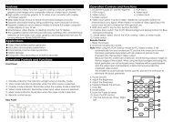
1-2 <strong>Power</strong> Control And Current Status Monitoring Diagram- 2 -
1-3 Product Features<strong>Professional</strong> IP-addressable power distribution unit with built-in web serverwith 4 power outlets.A new way to control power supply of the remote equipments via internetweb interface or telephone keypad without the presence of personnel.Amazing power distribution unit equipped with an intelligent current-meter(True RMS) to indicate the total power consumption of a power strip.Manual power on/off button to override the existing power status and gainimmediate control from local access.Each AC power outlet can be independently switched on/ off, power cycledfor immediate reboots or reboot with timed delays, power cycle sequencewith assigned priority and power event scheduling.Easy LED displays for power status, total current and control modeindication.Featured with AC (RMS) current meter built in to display the total currentload of the switch from the devices connected.Supports temperature monitor function to detect the monitored site'ssurrounding temp through the integrated temperature sensor.Supports <strong>Power</strong> Start sequence setting to prevent all of switches fromstarting simultaneously to cause sudden overloading and effect equipmentworking.Easy web setup for scheduling power operations precisely performed onspecific outlet daily, weekly, monthly and yearly.The Auto-Ping feature will monitor and auto detect any failed networkequipment and perform a timed reboot or other power control function (liketurning on an indicator or siren).IP filter/mask function helps manage user privileges and preventunauthorized access to the control menu through the network.Instant email, SMS text messages and trap notification will be generatedwhen power events occurred according to the preset values.Fail-safe RS-232 communication port connection available when networkis down or phone disconnected.Protected with circuit breaker to avoid power overload and protectconnected devices.Rack mountable design with holes on the side of the metal enclosure forwhen using optional rack-mounting kit.- 3 -
1-4 Hardware Environmental Explanation1 Console Connect <strong>Port</strong> (RS232) 7 Device running Indicating Light2 Phone Line Connect <strong>Port</strong> 8 Total Current Indication3 RJ45 Network Connect <strong>Port</strong> 9 Main <strong>Power</strong> <strong>Switch</strong>4 Phone Indicating Light 10 Breaker Protector5 Network Indicating Light 11 <strong>Power</strong> <strong>Switch</strong> Socket6 <strong>Power</strong> <strong>Switch</strong> Indicating Light- 4 -
1-5 <strong>Power</strong> Environmental Explanation<strong>Power</strong> SocketMax. Main Output Current<strong>Power</strong> Input<strong>Power</strong> FrequencyNEMA-15R15 Amp85~264VAC 47~63Hz50 - 60 HZOperating Temp. 0 – 60C (32 – 140F)Unit Dimension 332 x 153 x 44 mm (W x D x H)Machine Net WeightConsumption Efficiency4.2 lbs7 W1-6 Hardware Installation- 5 -
1-7 Product Packaging<strong>Remote</strong> <strong>Power</strong> Monitor * 1CD Rom of <strong>User</strong>’s Manual * 1<strong>Power</strong> Supply Cord * 1If any of the above accessories are missed or can’t be used, pleasecontact with the location you purchased for replacement in 7 days.- 6 -
2. Internet Web OperationIn this Chapter, you can learn how to set up this intelligent power controllerand configure the network setup, system time, power basic data and how tooperate power switch via network quickly.2-1 Online Setup1 Open up a web browser on your local computer and then enter“http://192.168.1.10” to get into the web session of this power managerunit.2 After the login screen appears, please enter “admin” in both accountpassword columns.- 7 -
3 When you key in the correct user’s name and password as theinstruction of Step 2, you will proceed to see the whole web controlinterface screen.2-2 Network SetupClick on【System】tab from the menu bar of the web screen and then clickon【Network】next for configuring the IP address and network info of this device.- 8 -
Network SetupPlease fill in the preferred IP address, sub network shade and thegateway info of your local area network . If you don’t have relevant dataon hand , please check back with your network system administrator orISP provider first.Domain Name Server SetupPlease fill in the DNS server information here provided by theadministrator or your ISP service provider. If you do not know the DNSserver information on your network, you may find out yourself byinputting C:\>nslookup in DOS prompt.Web Server SetupWhen you log into this remote power control unit through a webbrowser (e.g. Internet Explorer), you may change HTTPScommunication port to be other value like 8080 if you do not want to usethe default port number 443. And then you may re-login again to theremote power manager by re-entering the IP address of the remote IPpower unit plus the new HTTP port number you just assigned (e.g.https://192.168.1.10:8080 in this case) .After finishing all entry of network info, please make sure to store allsetup data into the unit by pressing the「Save」button on the web panel.2-3 Time SynchronizationThe time zone that our IP-P3 model adopts is 24-hour basis so you must set upthe timer schedule on this basis to the switch can perform accordingly. Whenaccessing this unit for the first time, you can have three time sync options tochoose from. By clicking the【Time Sync】button form the web control panel,- 9 -
you can choose which way to sync with for the system time of your remotepower controller.There are total of three system time synchronizers from the selection list:• Sync with A Local PC Clock:Select this method if you want to set up the equipment system time to bethe same as your PC’s date and time displayed in the web panel page.• Sync with NTP Server:Select this time method if you want the system time of this power switchto be the same as Greenwich Mean Time(GMT).• Manual Setup:You may also set up the system time of this power switch manually byentering the date and time you want this unit to be configured in thecolumns of Date and Time.* When you finish the date/time setup for the above step, always rememberto press the「Save」button on the web control panel to save all thesetting data in the system.- 10 -
2-4 <strong>Power</strong> Control Monitor ConfigurationYou can set up each individual power outlet on the switch accordinly withadvanced features by clicking on the【Monitor】tab from the Web controlpanel as illustrated in the following paragraph.2-4-1 <strong>Power</strong> <strong>Switch</strong> SetupClick the「Set」button located on the top corner of each power outleticon to set up set up the startup/shut down point with or without delayperiod. When the「Set」button is in orange color, the outlet ishighlighted and ready for configuration.The description colum under the「Configuration」section allows user toassign a nickname for the purpose of the individual outlet or the kindof the power equipment to be connected to.When finishing the setup for the above outlet, please make sure topress「Save」button to save the configuration that were just done.- 11 -
2-4-2 <strong>Power</strong> <strong>Switch</strong> OperationMove your mouse over to this section and left click on the mouse buttontwice to manually open or close any particular outputlet’s power fromthe web control panel at your networked computer terminal.Move your mouse over to each power outlet button icon and left clickon the mouse button twice to manually open or close any particularoutputlet’s power from the web control panel at your networkedcomputer terminal. If you want to reboot the individual outlet or theequipment connected to the outlet, check the 「Reboot」box and thenleft click on the mouse button twice to manually reboot any particularoutputlet’s power .- 12 -
3. Advanced SetupThis chapter is mainly to explain the advanced operation in the webcontrol panel. You may learn about all the advanced features and functions of<strong>Power</strong> Monitor, System Setup, Account Management, Time Synchronization,Event Record and Firmware Upgrade.3-1 <strong>Power</strong> MonitorThe first main category from the top menu bar of the web control panel is“Monitor”. In the section, users can proceed to set up the basic configuration,avalanched power operation scheduling, network device scan and detection ,power device temperature monitoring and voice control. All these tasks aredone through any internet browser.3-1-1 Warning Temperature SetupThis block is to display the total current , device temperature and thetemperature warning point.Device Temperature:Display the current temperature of this intelligentremote power switch. The built-in temperature sensor is able to detect thethe surrounding temperature at the monitored site. If the environmenttemperature rises, the temperature of this power swtich will go up too anddisplay on the upper right hand corner of the web panel.Warning Temperature: Administrator or system manager can set up thewarning point in this column so when the surrounding temperature reachesthe preset temperature point, a warning message will be sent outautomatically to all of the qualified users’ email accounts or cell phones.3-1-2 <strong>Power</strong> OperationAll 4 power outlets can be managed independently from the web controlpanel for power operation setups including power on, power off or rebootingthe power equipment.- 13 -
Button Icon Illustration: ON、 OFF、 NotAuthorized、 No <strong>Power</strong>3-1-3 <strong>Power</strong> Configuration SetupDescription:The description column allows for users to name each poweroutput after the connected power equipment or others for the convenienceof the system administrator/manager to distinguish all power equipmentsconnected from one to another.Start Delay Time: This column allows users to have each power deviceconnected start up at different moments instead of all starting up at thesame time. Each power outlet can be programmed to wait for the specifiedtime period in seconds or minutes before startup.Shutdown Delay Time:Just like the above the start delay time, this columnallows users to have each power device connected shut down at differentmoments instead of all shutting down at the same time.- 14 -
3-1-4 <strong>Power</strong> Operation SchedulingYou may program this remote power switch with timer schedule for action ofswitching the power equipment ON or OFF or reboot in this section.Recurrence:you can set the recurrence frequency of the power action foreach outlet. The recurrence can be yearly, monthly, weekly or daily.Time:Set up the action time for each power outlet. The time entry is on thebottom of the schedule tableAction:Select which power action to take place, ON, OFF or Reboot.Delete:If you want to delete this schedule, double-click on the “X” toconfirm the removal of the unwanted schedule entry.3-1-5 Network Detection PINGWhen the connected power equipment is a network IP-addressableequipment, you can set up this power switch to ping IP network devices soto confirm the continued operation of the equipment.Equipment Network Address:Enter the IP address of the networkequipment.PING Interval Time:Set the time Interval to execute the PING function onthe network equipment.Detect Times:If a device fails to respond to a ping continuously andexceeds the preset trial times, the switch will send the warning message oremail to the qualified personnel.Reboot:<strong>User</strong>s can set the power switch to reboot the web device If it fails torespond to a ping continuously and exceeds the preset trial times.- 15 -
Re-detect Time:<strong>User</strong>s can set the power switch to re-detect the connectedweb equipment here with preset time period in minutes.3-1-6 Temperature Monitor<strong>User</strong>s can arrange setup in this section in response to the abnormaltemperature detected by the remote power switch.<strong>Power</strong> Shutdown: In here users can set up the power shutdown pointwhen the power switch’s temperature is over the preset value for the presettime period, this intelligent remote power switch will shut down all the poweroutlets itself automatically for safety.Continuous Time:When the temperature of equipment power is reachingthe preset temp warning point and staying above the temp limit for thespecified time period, this intelligent remote power switch will shut down allthe power outlets itself automatically for safety.<strong>Power</strong> Start:Set up the power start up point If the power switch cools downand its temperature drops to the preset value, this remote power switch willrestart again and back in operation automatically.3-1-7 Voice File Sending<strong>User</strong>s can record their voice in files and load the files to the power switchwhen in control by phone.Click「Browse」button and then choose the voice file you want to upload tothis switch, and then press「Begin Upload」.The Voice File <strong>For</strong>m is PCM/A-Law/u-Law 8K 8Bit and less than 40K (about5 seconds ). In regards to the recording operation for Voice File, pleaserefer to Attachment B.- 16 -
3-2 System SetupIn this section you may learn to set up telephone-control related data,web/network, email server and message services.3-2-1 Network SetupIP network information data entry:IP Address:Assign the Network IP address for the power switch.Subnet Mask:Set up the subnet mask info of this equipment.Gateway:Set up the gateway port of this equipment.DNS Server 1:Enter your DNS server1 address if any.DNS Server 2:Enter your DNS server2 address if any..Http <strong>Port</strong> Open:Check this box to allow remote user to access thisequipment via a web by http protocol.Http <strong>Port</strong>: Assign a HTTP port address here for browsers to be connectedto this equipment via HTTP protocol.Http SSL <strong>Port</strong> Assign a SSL port address here for browsers to be connectedto this equipment via HTTP SSL protocol.- 17 -
API <strong>Port</strong>: Provide the Application Program to be connected with theappointed connect port to this equipment. This product provides API forthe user to develop program connected with this equipment to get thepower, electric current, temperature status and control power (please referto the explanation 6-3.) You must setup the network vent connecting theprogram with this equipment.3-2-2 Email Server SetupWhen there is a triggered warning from the setup of this power switch, thisdevice will send out an alert message to the preset email accounts.SMTP Server Address:Enter your SMTP server address here .SMTP <strong>Port</strong>:Enter your SMTP port number here. The preset value is 25.Sender Mail Address:This section will be displayed in where the alert emailis sent from.Mail Subject:When the Receiver gets the email, it will be revealed inSubject data of email.SMTP Auth:If the setup mail server needs to identify the user, please markthis item and setup the account and password.SMTP Account:Enter the user id here for SMTP account if needed.SMTP Password:Enter the password here for SMTP account if needed.- 18 -
3-2-3 Message Server SetupWhen there is a warning, setup the warning message data in the MessageServer.Server Address: Enter the SMS message server’s IP address here so theSMS text message can be transmitted to the SMS server when the warningevent is triggered by the preset value.<strong>Port</strong>:Enter the connection port address for your SMS message server. Thepreset value is 2500.Equipment Name: When the receiver gets the text message sent by theSMS server, this portion will display the source of the SMS alert event.Account:Enter the user id of your SMS server if available.Password:Enter the password of your SMS server if available.Send SMS:Check here if SMS service needs to be activated for operationsetup.- 19 -
3-2-4 SNMP SetupSystem Name:Display System Name on the program of SNMP Client.System Contact:Display System Contact Person on the program of SNMPClient.System Location:Display System Site on the program of SNMP Client.Receiver IP Address:When something happens to Trap and it is IP site whichwill be sent to Trap.Receiver <strong>Port</strong>:When something happens to Trap and intends to send to Trapserver, it is the Connect <strong>Port</strong> for Trap server. The inner setup value is 162.Community:When something happens to Trap and intends to transmit to Trapserver, the group will be sent to Trap server.Enabled:While mark the using option, if something happens to Trap, TrapCase Information will be sent to the appointed Trap server.3-2-5 Other SetupsThe phone ring setup is designed for phone control mode. This system willexecute IVR process after several rings. If there are no other phone devicesattend to the incoming call, this power switch will take the call then.- 20 -
When this intelligent remote power switch is daisy chained with other phonedevices like fax machine or answering machine, you can set the lowerpriority on this power switch by assigning more rings needed so to let usersor other phone devices to attend the phone call first.Answering Ring Setup:Set up the number of phone rings beforeanswering.Reboot <strong>Power</strong> <strong>Switch</strong>:Check this box here if the reboot of the power switchis needed.Reboot Device:Reboot the switch.3-3 Account ManagementClick the【Account】tab from the menu of the web control panel and thenproceed to set up the authorizied users’ accounts and other account accessmanagement. You may set up to 4 accesss accounts in total.3-3-1 Account AddAccount:Set up the user id of each user account here.Password:Set up the password of each user account here.- 21 -
TEL Password:Set up the phone control password of each user account herewhen accessing this power switch via telephone, callers will be prompted toenter the phone 6-digit pass code before logging into the power switch.Cell phone:This is an optional setup if SMS messenger server is available.Enter contact phone number here when the alert SMS text message needs tobe transmitted via the designated SMS server.Mail Address:Enter contact email address here when the alert message needsto be transmitted by email service.Administrator or system manager of this power switch can also assign theaccess levels for each user account. <strong>For</strong> example manager can assign user Ato access either all 4 power outlets on the switch or just a particular one outlet isallowed for access.3-3-2 Delete <strong>User</strong> AccountChoose and mark to delete <strong>User</strong>’s Data.Press「Delete」button to proceed the action of deleting <strong>User</strong>’s Data.After deleting the data, you must press「Save」button to store the deletingsetup really.- 22 -
3-4 Time SimultaneityEquipment Date:The system date of the remote power switch.Equipment Time:The system time of the remote power switch.Sync with PC:If you choose this item, the equipment time of the remote powerswitch will be the same as the computer system.PC Date: The current computer system date.PC Time:The current computer system Time.Sync with NTP Server :If you choose this item, the equipment time and TimeServer will be identical.NTP Server Address:This switch provides several Time Servers for choice. Ifthere is no time server info you want in the list, you may also add a new TimeServer info by yourself and then set up the time. Press「New」button, when thewindow below appears, input the NTP server address and then press 「OK」.- 23 -
3-5 Event LogIn this section, you may check the log of all the power operations andwarning events in the recent 7 days. You can find out what power actionoccurred on what outlet and at what time by access remotely or locally from theweb panel. At the same time, if the power switch can not operated normally, itwill produce warning case.Click to choose “Operated Event” or “Warning Event” and choose date fromdate bar, then press "OK" button , It will show the event information.The “Download” button means that users can save the event log informationin .cvs format into the hard drive. “Delete” button means to delete thehighlighted event information..- 24 -
4. Phonetic Operation ProcedureThis chapter is mainly to explain the operation procedure for phonetic controlsystem of this remote power switch. <strong>User</strong>s can use any telephone keypad toremote control the power switch. <strong>User</strong>s can read the total of the electric currentfrom all outlets, device’s current temperature and so on. This chapter is dividedinto 3 sections including the Main Procedure, the <strong>Power</strong> Control Procedure, and<strong>Power</strong> Electric Current Procedure.This remote switch will disconnect the caller and release the phone line if thereis no response received after being connected with the power switch by phonefor over 5 seconds.※ The telephone control passcode for this power switch system is“123456”.- 25 -
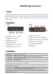
4-1 Main Procedure- 26 -
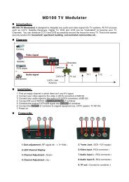
4-2 <strong>Power</strong> Control Procedure- 27 -
Attachment (A):How to reset this remote power switch to the initial defaultvalue ?Answer: In case that user forgot the password for the web network access tothe power switch, user can always reset the power switch back tomanufacturer’s default setting.Locate the “RESET” button first. There is a small tiny hole next to the “TEL” and“LAN” LED indicating light. That’s where you can reset the power switch. Youmay insert any pointed object like a paper clip into this hole to push gently andhold for at least 3 seconds then release the push. Then the remote powerswitch shall carry out the reboot for system reset .Typically after a successful reset, the phone indicating light will flash and thenthe machine will be reboot in a few seconds.Note: After reset, this device will clear the previous user id and password dataentry. However the rest of the user access information and other data entry willbe kept the same as before. Both the user id and password for the web access session will be back to“admin” for ID and “admin” again for the password. The telephone pass code will be returned to “123456 “. The network IP address of this switch will be 192.168.1.10. The rest of the system setup data will remain unchanged.- 28 -
Attachment (B):How to use audio tape recorder to record the voice filerepresenting the power equipment connected to the powerswitch in the phone control mode ?You can utilize the sound recorder procedure in Windows to record voice andthen upload the voice file to this power control system file for equipment’s voiceannouncement.Start up the sound recorder application in Windows first.Turn on the recorder [File / Properties ], after selecting, press the voice filecontent transform to CCITT u-Law 8KHz 8 bytes.- 29 -
Save the recorded voice file to the directory you appointed.- 30 -
Upload the pre-recorded voice file to the remote power switch. (please referto 3-1-7)- 31 -