
Create successful ePaper yourself
Turn your PDF publications into a flip-book with our unique Google optimized e-Paper software.
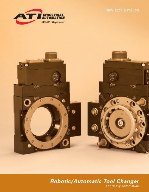
NEW 2005 CATALOG<strong>Robot</strong>ic/Automatic Tool ChangerFor Heavy Automation
TOOL CHANGERS FOR HEAVY AUTOMATION<strong>Robot</strong>ic Tool Changers for HeavyAutomationThe Heavy Automation <strong>Robot</strong>ic Tool Changer linehas been developed for the resistance welding marketand medium- to heavy-duty material handling. Becausethese <strong>tool</strong> <strong>changers</strong> use modules to pass utilities (e.g.water, electrical, pneumatic, etc.), they are able to handlenumerous applications by simply selecting thedesired modules. These <strong>tool</strong> <strong>changers</strong> have extremelyhigh moment capacity for use in heavy-duty applications.Product AdvantagesModular Design: Power, coolant, servo, DeviceNet,and signal features are built into separate modules makingmaintenance easy. Module housings use a commonmounting design for use on the QC-210, QC-310 andQC-510, increasing flexibility in configuring the <strong>tool</strong>changer.High-flow fluid module: The Fluid/Air module has a Cvof 1.65 (1.65 gallons of water per minute for 1 psi pressuredrop) allowing for better weld gun and transformercooling.Product EnhancementsOur staff of engineers and designers have made manydesign improvements that enhance the performanceand functionality of these <strong>tool</strong> changer models.Common Accessory Module Mounting: Modulesmount from the <strong>tool</strong> changer face to provide extra supportfor applications with large dress packages. All modulesuse a common mounting pattern so they can beswapped between the QC-210, QC-310 and QC-510models and located on any of three available flats.Extremely High Moment Capacity: Many <strong>tool</strong> <strong>changers</strong>with high moment loads gap (separate between themaster and <strong>tool</strong> plates) during high-speed moves, causingdisruption to utilities such as servo lines. The heavyautomation series from ATI can take on dynamicmoment loads and maintain utility functions during fullrange of motion.Integrated Solution for DeviceNet: The DeviceNetmodule with integrated valve is internally plumbed andinterfaces with internal cable routing in the <strong>tool</strong> changerbody.Easy Dress: The modules are designed to place electrical,pneumatic and water ports in-line, affording the customeran easy dress-out.Battery Backup for Servo: The servo module has abattery backup option on the <strong>tool</strong> side to allow the servoto hold information while disconnected from the robot.Strong Power and Servo Module Housing: The primarycurrent and servo modules use an aluminum housingto prevent damage from cable stress and crashes.Weight and Size Reduction: Weight and size are keptas small as possible without reducing reliability or performance.No-Touch Contacts Increase Safety: 200-amp powerand signal modules have contacts that are not touchableon the Master side—increasing safety and world wideacceptance.QC-210 Module to Body ConnectionIn-the-Body Sensing: Lock/Unlock/Ready-to-Lock sensorshave been integrated into the body of the <strong>tool</strong>changer. This design provides the advantages ofreduced stack height and reduced weight without sacrificingthe strength of the unit. Two (2) Ready-to-Locksensors in the body affords the robot programmer theability to better teach master-to-<strong>tool</strong> coupling.High Strength: Design improvements to the alignmentpins and bushings have increased the moment capacityof both the QC-210 and QC-310.Integrated Bolt Circle Patterns: Common, industrystandardbolt circle patterns have been integrateddirectly into the <strong>tool</strong> changer body of these models,eliminating the need for an interface plate and reducingstack height.2 VISIT WWW.ATI-IA.COM FOR CURRENT PRODUCT SPECIFICATIONS, 2-D DRAWINGS, AND 3-D CAD MODELS
QC-310<strong>Robot</strong>ic Tool Changer for HeavyAutomationQC-310 with AA2 Pneumatic module and DH3/DH2InstaTool modules for DeviceNetProduct AdvantagesNo-Touch Locking technology allows up to 10mm plate separation when locking.Ready Sensors (2) detect when the Tool plate iswithin 1.5 mm of the Master plate, signaling readyto-lock.Patented Fail-safe locking mechanism• Locking mechanism design results in lowforce acting on the piston.• Large piston diameter and outward ball travelincrease moment capacity.• All locking parts are made of R c 58 stainlesssteel.Integrated Lock/Unlock Sensing for safety.Mounts Directly to most 500 Kg <strong>Robot</strong>s(no SIP required; see unit height below)Specifications Values CommentsSuggested Payload Limit 1,120 lbs The mass attached to the <strong>tool</strong> changer. Higher payloads500 kg possible with moment rating.Locking Force @ 80 psi 7,940 lbs Axial holding force.35,333 NStatic Moment Capacity (X & Y) 29,100 lb-in Higher dynamic moment possible depending on module3,870 Nm selection. Failure test exceeded 180,000 in-lb moment.Static Moment Capacity (Z) 28,000 lb-in (Torsion) Higher dynamic moment possible depending on module3,150 Nm selection. Failure test exceeded 100,000 in-lb moment.Positional Repeatability (X,Y, & Z) .0006 in Repeatability tested at rated load at over one million cycles..015 mmWeight (when coupled) 44.0 lbs Master: 27.5 lbs (12.5 kg)(no accessory modules) 20.0 kg Tool: 16.5 lbs (7.5 kg)Unit height when locked 4.72 in Stack Height - 200mm ISO pattern120.0 mmUnit size (no modules) 9.6 x 9.6 in Size of body prior to module mounting244 x 244 mmMaximum allowable distance between 0.4 in Normal recommended locking distance. Locking distancemaster and <strong>tool</strong> plates before locking 10 mm varies depending on module selection, lock pressure, payload, etc.Sensor Information, signal name L/U/RTL Lock/Unlock sensors (2) integrated into the body of the(Lock/Unlock/ <strong>tool</strong> changer. (2) Ready Sensors, 180 degrees apart,R1 and R2) afford easier teaching for the robot programmer.4 VISIT WWW.ATI-IA.COM FOR CURRENT PRODUCT SPECIFICATIONS, 2-D DRAWINGS, AND 3-D CAD MODELS
QC-510<strong>Robot</strong>ic Tool Changer for HeavyAutomationQC-510 with AA2 Pneumatic module and DH3/DH2InstaTool modules for DeviceNetProduct AdvantagesNo-Touch Locking technology allows up to 10mm plate separation when locking.Ready Sensors (2) detect when the Tool plate iswithin 1.5 mm of the Master plate, signaling readyto-lock.Patented Fail-safe locking mechanism• Locking mechanism design results in low forceacting on the piston.• Large piston diameter and outward ball travelincrease moment capacity.• All locking parts are made of R c 58 stainlesssteel.Integrated Lock/Unlock Sensing for safety.Mounts Directly to most 1000 Kg <strong>Robot</strong>s(no SIP required; see unit height below)Specifications Values CommentsSuggested Payload Limit 1,325 lbs The mass attached to the <strong>tool</strong> changer. Higher payloads600 kg possible with moment rating.Locking Force @ 80 psi 14,000 lbs Axial holding force.62,300 NStatic Moment Capacity (X & Y) 43,000 lb-in Higher dynamic moment possible depending on module4,680 Nm selection. Failure test exceeded 250,000 in-lb moment.Static Moment Capacity (Z) 31,000 lb-in (Torsion) Higher dynamic moment possible depending on module3,500 Nm selection. Failure test exceeded 150,000 in-lb moment.Positional Repeatability (X,Y, & Z) .0006 in Repeatability tested at rated load at over one million cycles..015 mmWeight (when coupled)Unit height when locked63.3 lbs28.7 kg5.8 in147.3 mmUnit size (no modules) 10.4 x 10.4 in Size of body prior to module mounting264 x 264 mmMaximum allowable distance between 0.1 in Normal recommended locking distance. Locking distancemaster and <strong>tool</strong> plates before locking 2.5 mm varies depending on module selection, lock pressure, payload, etc.Sensor Information, signal name L/U/RTL Lock/Unlock sensors (2) integrated into the body of the(Lock/Unlock/ <strong>tool</strong> changer. (2) Ready Sensors, 180 degrees apart,R1 and R2) afford easier teaching for the robot programmer.VISIT WWW.ATI-IA.COM FOR CURRENT PRODUCT SPECIFICATIONS, 2-D DRAWINGS, AND 3-D CAD MODELS 5
PRODUCT DRAWINGSATI INDUSTRIAL AUTOMATION www.ati-ia.com QC-210 9230-20-2172-01QC-210 with DH3/DH2, AA2 modulesATI INDUSTRIAL AUTOMATION www.ati-ia.com QC-310 9230-20-2173-01QC-310 with DH3/DH2, AD2 modules6 VISIT WWW.ATI-IA.COM FOR CURRENT PRODUCT SPECIFICATIONS, 2-D DRAWINGS, AND 3-D CAD MODELS
ATI INDUSTRIAL AUTOMATION www.ati-ia.com QC-510 9230-20-2174-01QC-510 with DH3/DH2, AA2 modulesVISIT WWW.ATI-IA.COM FOR CURRENT PRODUCT SPECIFICATIONS, 2-D DRAWINGS, AND 3-D CAD MODELS 7
MODULESThe Heavy Automation Series Tool Changers are extremely diverse <strong>tool</strong> <strong>changers</strong> with the ability to perform in awide variety of applications. This flexibility is due in large part to the many different models of modules designed topass a variety of utilities,such as:• Fluid/Air modules• 200-amp primary current module for transgunapplications• DeviceNet modules supporting Master and Toolside nodes and “Quick” connect times• Patent-pending InstaTool TM modules from ATI thatdrastically decrease connect time in DeviceNetenvironments• Discrete signal module with <strong>tool</strong>-ID built-in• Servo module with optional battery backup• 600-amp module for high power and groundapplications• more…Our new Tool Changer design allows modules to be fully interchangeable on 3 of the 4 flats. Flat A is reservedfor air/valve adapters and control/signal modules. Please contact ATI with any special requirements.AIR AND VALVE ADAPTERSThe Air and Valve adapters provide an interface for thecustomer to supply the necessary pneumatics for actuationof the <strong>tool</strong> changer locking mechanism.Basic arrangements come outfitted with an Air adaptermounted to Flat 'A' of the <strong>tool</strong> changer master providingseparate Lock and Unlock ports for customer connection.In this case, the customer is responsible forcontrolling the pneumatic signal supplied to the <strong>tool</strong>changer to either "Lock" or "Unlock" the <strong>tool</strong> changer.More advanced units come outfitted with integratedsingle or double solenoid valves mounted to Flat 'A' ofthe <strong>tool</strong> changer master. In this case, a pneumatic supplyconnection is provided for customer interface.Air and Valve AdapterAn electrical connection is also provided for customerinterface and control of the valve. In some cases, controlof the integrated valve is accomplished through anaccessory electrical module.CONTROL / SIGNAL MODULES - DISCRETEA variety of electrical modules are available that offerdiscrete signal pass-through for the <strong>tool</strong> changer. Someof these modules work with an integrated double or singlesolenoid valve for lock/unlock control of the <strong>tool</strong>changer. Some modules are also available supporting<strong>tool</strong> changer I/O, such as lock, unlock and ready-to-lockproximity sensors as well as Tool ID.Military-style connectors are standard on most electricalmodules. Custom versions are available upon request.VB2 Discrete Signal Modules8 VISIT WWW.ATI-IA.COM FOR CURRENT PRODUCT SPECIFICATIONS, 2-D DRAWINGS, AND 3-D CAD MODELS
CONTROL / SIGNAL MODULES - DEVICENETElectrical Feed-throughTwo (2) standard “mini” style power and signal connectorsare provided for ODVA-compliant DeviceNet interfacingon the Master and Tool modules. When the <strong>tool</strong>changer is coupled, the Master and Tool DeviceNetmodules communicate with each other using a springloadedpin block. A flexible boot surrounds the pin blockto seal the connection from moisture and liquid whilecoupled.Pneumatic ValveA double solenoid-actuated pneumatic valve is integratedwith the DA2 DeviceNet Master module for controlof the locking mechanism. A single solenoid with springreturn is used for the DB2 module.Tool Stand InterlockThe DeviceNet modules are outfitted with a Tool StandInterlock (TSI) connector that is wired directly into theunlock solenoid valve circuit. The DA2 module TSI islocated on the master, while the DB2 module TSI islocated on the <strong>tool</strong>. Using this connector, a switch canbe integrated that will allow the solenoid valve to uncouplethe <strong>tool</strong> changer only when the <strong>tool</strong> is in the <strong>tool</strong>stand. Teach plugs are available to close the solenoidvalve circuit during setup and maintenance scenarios.Tool IDThe DeviceNet Tool module uses a series of five 0–9switches for setting Tool ID. This allows thecustomer to distinguish between the different Tools thatare being operated and controlled through theDeviceNet network.FLUID, AIR AND VACUUM MODULESThere are a variety of modules that pass fluid, air andvacuum utilities.Fluid/Air modules are made from stainless materials toavoid corrosion. Master and Tool modules comeequipped with check, self-sealing ports to minimizefluid/air loss during a <strong>tool</strong> change.Checked, self-sealed ports utilize a u-cup seal and cannotsupport vacuum service. Similarly, vacuum ports utilizinga v-ring for seal purposes cannot support positive pressures.Air modules are made from anodized aluminum materials.Numerous variations are available which offerchecked, self-sealing and passthrough ports. Ports supportingvacuum service utilize a v-ring to obtain a sealbetween master and <strong>tool</strong> modules.Unchecked pass-through air ports utilize rubber bushingsto achieve a durable, reliable, long-lasting seal betweenMaster and Tool.AA2 Pneumatic ModuleVISIT WWW.ATI-IA.COM FOR CURRENT PRODUCT SPECIFICATIONS, 2-D DRAWINGS, AND 3-D CAD MODELS 9
ATI INSTATOOL MODULES FOR DEVICENETNew Innovation Greatly Reduces Timeand Complexity for Tool Changes inDeviceNet Environments.DeviceNet is a popular industrial communications busused to connect industrial devices and reduce or eliminatetime-consuming discrete wiring.The ProblemWith the obvious benefits of DeviceNet technologycomes the inevitable delay that occurs during <strong>tool</strong>identification—as long as 8 seconds at each <strong>tool</strong> change.The cumulative effect of these delays is a loss of productiontime. This compounded effect becomes a factor inreducing manufacturing productivity.In an effort to minimize this delay, a new DeviceNetstandard (Quick Connect) has been released whichcould potentially reduce this delay to 2 to 3 seconds.This is still a noticeable delay during an applicationprocess.ATI InstaTool solves the problem.The Solution: ATI InstaTool TechnologyWith ATI InstaTool , long delays for <strong>tool</strong> identification and<strong>tool</strong>ing I/O are a thing of the past. By using ATI InstaTool technology, the new <strong>tool</strong>-side module communicates<strong>tool</strong> ID and <strong>tool</strong>ing I/O to the master/robot module injust tenths of a second after <strong>tool</strong> changer coupling. Thereis no longer a need to establish a DeviceNet node on the<strong>tool</strong> side, which in turn prevents power-ups from havingto negotiate lengthy DeviceNet protocol sequences.Tooling is available on the network in under a second.DH3-M/DH2-T InstaTool modules for DeviceNetBest of all, there are no costly upgrades of DeviceNetscanner and master controller equipment required toenjoy the substantial benefits of ATI InstaTool .Product AdvantagesNear-Instant Connection and Tool Identification:With InstaTool, <strong>tool</strong> ID occurs within 150 milliseconds, ascompared to up to 8 seconds using current technology.Tool I/O is available within 700 milliseconds.Reduction in Time: No delay means overall cycle timeis reduced and production is increased. This advantageis heightened in applications with multiple <strong>tool</strong> changes.Reduced DeviceNet Node Management: With ATIInstaTool and InstaBus technology, the <strong>tool</strong> changermaster node handles 160 I/O points downstream,resulting in fewer DeviceNet nodes to manage.Tool ID Passes Through Master: Systems with multiplemasters and <strong>tool</strong>s can positively identify which <strong>tool</strong>s areconnected to each master.ATI InstaToolNew QuickConnectMaximum Time from Tool Connectto Tool ID ReadTool Stand Interlock (TSI): A <strong>tool</strong> stand interlock featureis provided on the <strong>tool</strong>/slave side for safer <strong>tool</strong> changeroperation. The TSI allows uncoupling only when the <strong>tool</strong>changer is in the <strong>tool</strong> stand. Customers have the optionto choose mechanical or proximity sensor switches toclose the TSI circuitry.Additional Safety Features: Additional DeviceNet inputsare provided to identify unsafe operating conditions.Customer operating software can be programmed tohalt <strong>tool</strong> changer operation when unsafe conditions exist.Old DeviceNet0 2 4 6 8 10Time (Seconds)10 VISIT WWW.ATI-IA.COM FOR CURRENT PRODUCT SPECIFICATIONS, 2-D DRAWINGS, AND 3-D CAD MODELS
DeviceNet—With and Without ATI InstaTool The illustrations below indicate the fundamental differencesbetween standard DeviceNet connectivity and the new ATIInstaTool technology.Standard NetworkBefore ATI InstaTool , the DeviceNet signal passedfrom the DeviceNet controller, through the masterside to the <strong>tool</strong> side of the <strong>tool</strong> changer, then on todownstream nodes. With this method, each time anew <strong>tool</strong> side connection is made, up to an 8-secondstart-up delay occurs before <strong>tool</strong> identification anddownstream I/O can be read and the application cancontinue.ATI SolutionWith InstaTool , the DeviceNet signal effectively stopsat the <strong>tool</strong> changer master, creating an always-on connectionto that master node. Using patent-pendinghigh-speed technology, the master node handles allI/O communication downstream from the master. Theresult is a connect time of less than 150 millisecondsfor <strong>tool</strong> ID and under 700 milliseconds for <strong>tool</strong> I/O.Tool I/O appears at the master node.Up to160 I/OVISIT WWW.ATI-IA.COM FOR CURRENT PRODUCT SPECIFICATIONS, 2-D DRAWINGS, AND 3-D CAD MODELS 11
MODULESPRIMARY POWER MODULESThe Primary Power Module is designed to carry primarycurrent from a power supply to a transgun attached tothe Tool. It consists of three Rhodium-plated coppercontacts, each capable of carrying 200 Amps at up to600 volts To avoid arcing never uncouple the ToolChanger without first turning off the power supplyto the Master. The installation of over-current protectionin the primary power circuit is recommended.Transferring CurrentThe modules use advanced, patented, cone-matingtechnology to transfer current from the Master to theTool. The mating conical surfaces provide a large contactarea, excellent misalignment capability and allowefficient coupling/uncoupling, without high spring forcesor excessive wear. The central contact on the <strong>tool</strong> sidemodule is extended for use as a first-make/last-breakground contact. If required, the Master or Tool contacttips can easily be replaced without removing the wiring.Safety FeaturesThe contact tips on the master side are recessed andcontain a center insulator post to insure that the fingerof an average adult cannot touch the metallic parts. Theinterior of the module housings are insulated electricallywith a thick, hard anodized coating and high dielectricmaterial.Cable InstallationBy removing the protective cover the customer hasaccess to the three contact bases. Each contact baseutilizes split-bolt clamping to secure up to #2 AWGwelding cable.Customer supplied cord grips secure the power cableto the module using optional fitting plates. Plates areavailable in PG29, 1-1/2 NPT and 1-1/4 NPT. The customeris encouraged to use both EMT jam nuts and theset screws supplied with the fitting plates to preventthe strain relief fittings from working loose with robotmotion.SERVO MODULESA servo module may be provided on the <strong>tool</strong> changer tosupport power and signal connections to a servomotor.Compliant spring probes are provided on the master sideand fixed contact pins on the <strong>tool</strong> side. By design, boththe signal and motor power circuits are separated andelectrically isolated from each other and from the <strong>tool</strong>changer. The circuits also have EMI/RF shielding to protectthem from noise.FeaturesThe <strong>tool</strong> side center contacts are extended on both thepower and signal circuits to provide first-make/last-breakprotection and are used to pass protective ground whenpossible. The master side contacts are recessed to preventaccidental contact. The modules are designed to bewater resistant.ImportantTo avoid damage to the contacts, never uncouple theunit without first disconnecting and discharging powerpassing through these pins.Design ParametersServo applications may involve motors and positionfeedback devices from different vendors. ATI addressesthis by utilizing a modular design incorporating separatecustomer specified power and signal connectors andwiring.Contact ATI to determine if there is already a designmeeting your requirements. This is easily determinedwhen the customer provides copies of the servo cabledrawings showing the connectors and wiring pin out.We welcome the opportunity to design a module foryour application.12 VISIT WWW.ATI-IA.COM FOR CURRENT PRODUCT SPECIFICATIONS, 2-D DRAWINGS, AND 3-D CAD MODELS
MODULES AND OPTIONSFluid/Air ModulesPart # DescriptionFB2-M/T (8) 3/8" NPT Ports, Master - 8 Checked Ports, Tool - 4 Checked/4 Unchecked PortsFB3-T (8) 3/8" NPT Ports, Tool, 8 Unchecked PortsFB4-T (8) 3/8" NPT Ports, Tool, 8 Checked PortsFC2-M/T (8) 3/8 G Ports, Master - 8 Checked Ports, Tool - 4 Checked/4 Unchecked PortsFC3-T (8) 3/8 G Ports, Tool, 8 Unchecked PortsFC4-T (8) 3/8 G Ports, Tool, 8 Checked PortsPneumatic ModulesPart # DescriptionAA2-M/T (2) ½" NPT Ports, 2 Checked Ports, Master and ToolAA3-T (2) ½" NPT Ports, 2 Unchecked Ports, Tool sideAB2-M/T (8) 3/8" NPT Ports, Master - 8 Checked Ports, Tool - 4 checked/4 unchecked portsAB3-T (8) 3/8" NPT Ports, Tool, 8 Unchecked PortsAB4-T (8) 3/8" NPT Ports, Tool, 8 Checked PortsAC2-M/T (4) 3/8" NPT Ports, 4 Checked, (2) ¾" NPT Vacuum Ports, Master and ToolAD2-M/T (2) ¾" NPT Ports, 2 Checked Ports, Master and ToolAG2-M/T (4) 3/8 G Ports, 4 Checked, (2) ¾ G Vacuum Ports, Master and ToolAH2-M/T (8) 3/8" G Ports, Master- 8 Checked Ports, Tool - 4 Checked/4 Unchecked PortsAH3-T (8) 3/8" G Ports, Tool, 8 Unchecked PortsAH4-T (8) 3/8" G Ports, Tool, 8 Checked PortsAJ2-M/T (10) ¼" NPT Ports, 10 Checked Ports, Master and ToolAK2-M/T (10) ¼" G Ports, 10 Checked Ports, Master and ToolPrimary Power ModulesPart #PA2-M/TPB2-M/TDescriptionPrimary Current Master or Tool, (3) contacts, 2/O wire, 200A, 600V ratingPrimary Current Master or Tool, (2) contacts, 2/O wire, 200A, 600V ratingServo Modules - Consult ATIATI custom engineers modular assemblies for servo applications. Refer to page 12 and contact ATI with your requirementsto determine if we already have a module to fit your needs. We welcome the opportunity to custom design amodule for your application.14 VISIT WWW.ATI-IA.COM FOR CURRENT PRODUCT SPECIFICATIONS, 2-D DRAWINGS, AND 3-D CAD MODELS
HOW TO ORDER9121- 10 - - - - -S QC-210, QC-310, and QC-510Flat ‘A’ Flat ‘B’ Flat ‘C’ Flat ‘D’Standard Proximity Switch designationG: PNP Quick-disconnect switchFor information on other switches, contact ATI Sales.Optional ModulesRefer to the tables on pgs. 13-14 for information neededto select the proper module for your application.A comprehensive list is available at www.ati-ia.com.Note: Flat ‘A’ Master must always have a Jxx Air/ValveMounting Adapter. Signal Modules can be located on flat‘A’ and are piggy-backed on the ‘Jxx” Air/Valve MountingAdapter. When a DeviceNet or Discrete Module is specified,the first set of placetakers is comprised of a combination of Air/Valve Adapter and Signal Module, e.g.9121-210BM-JC2DD4-AA2-0-0-SGJxx: Air/Valve Mounting Adapter (‘A’ Flat Only)Axx: Air Module (Anodized Aluminum, No fluid)Dxx: DeviceNet Module / InstaTool ModuleExx: Servo ModuleFxx: Fluid/Air Module (Stainless steel, checked ports)Pxx: Power ModuleSxx: Discrete Signal ModuleUxx: Stud Feeder ModuleVxx: Discrete Signal Module with Integrated Valve‘0’ Represents a flat with no moduleM: MasterT: ToolBoss/RecessA: No Boss (Master) or Recess (Tool)B: 80mm Boss/Recess (only available on 210)C: 100mm Boss/Recess (only available for 210, 310)D: 125mm Boss/Recess (only available for 310, 510)E: 160mm Boss (only available for 510)Model Designation2: QC-2103: QC-3105: QC-510VISIT WWW.ATI-IA.COM FOR CURRENT PRODUCT SPECIFICATIONS, 2-D DRAWINGS, AND 3-D CAD MODELS 15
QC-602<strong>Robot</strong>ic Tool Changer for ExtremeMaterial HandlingThe QC-602 <strong>Robot</strong>ic Tool Changer from ATI is by far thestrongest <strong>tool</strong> changer on the market today. Typicallyused by gantry applications, the QC-602 was designedto meet the extreme payload and moment demands ofheavy industrial and aerospace applications. With a payloadcapacity of 2,500 pounds, the QC-602 is in a classof it’s own, setting a new standard in heavy capacity<strong>tool</strong> <strong>changers</strong>.Product AdvantagesNo-Touch Locking technology allows up to 0.1 in.plate separation when locking.Patented Fail-safe locking mechanisms• Locking mechanism design results in low force actingon the piston.• Large piston diameter and outward ball travelincrease moment capacity.• All locking parts are made of Rc58 stainless steel.Integrated Lock/Unlock Sensing for safety,Highest Moment Capacity: 3 locking mechanism designcreates static moment capacity of 122,000 lb-in. (X & Y)QC-602SpecificationsSuggested Payload LimitLocking Force @ 80 psiStatic Moment Capacity (X & Y)Static Moment Capacity (Z)Positional Repeatability (X,Y, & Z)Weight (when coupled)Unit height when lockedMaximum allowable distance betweenmaster and <strong>tool</strong> plates before lockingSensor Information, Signal NameMounting Surface/Customer InterfaceLock/Unlock Air SupplyPneumatic pass-through portsValues2,500 lbs1,130 kg21,000 lbs9,525 kg122,000 lb-in13,750 Nm49,000 lb-in5,500 Nm.0006 in.015 mm128.1 lbs58.1 kg5.51 in139.91 mm0.1 in2.54 mmL/U (Lock/Unlock) Proximity SensorsRTL (Ready-to-Lock) Proximity SensorsCustom patterns for Master plate and Tool plate basedon three (3) QC-200 locking mechanisms3/8 NPT3/8 NPT – Two (2) air ports which are uncheckedThe QC-602 is designed to work with a variety of accessory modules from the ATI Standard SeriesTool Changers. A complete list of compatible modules is available online at www.ati-ia.com.16 VISIT WWW.ATI-IA.COM FOR CURRENT PRODUCT SPECIFICATIONS, 2-D DRAWINGS, AND 3-D CAD MODELS
HOW TO ORDER-0- - -0- -9120-602 QC-602Type of Lock SensingC – AC E – NPN G – PNP 0 – No module in placeOptional Modules for Flat ‘E’(1) J16 Pattern V114 Vacuum Module 0 – No module in placeFlat ‘D’Blank – for future developmentOptional Modules for Flat ‘C1’ and ‘C2’(1) J16 Pattern to support Various Modules(ex. R21, T19, S19, J16, MT8)0 – No modules in placeFlat ‘B’Blank – for future developmentM: MasterT: ToolSignal Module for Flat ‘A’ *TF19, TW19, TF26* Please visit www.ati-ia.com for an updated, comprehensive list ofmodules. As always, consult your ATI Account Manager with anyquestions regarding product selection for your application.2D drawings of the QC-602 are available at www.ati-ia.com.VISIT WWW.ATI-IA.COM FOR CURRENT PRODUCT SPECIFICATIONS, 2-D DRAWINGS, AND 3-D CAD MODELS 17
MODULAR TOOL STANDSThe ATI TSL (Tool Stand,Large) Modular ToolStand System, or TSL, iscompatible with largerATI Tool Changers. TheStand is designed fordurability, longevity, andmaximum flexibility to fitmost customers’ applications.The configurablesystem allows you tospecify <strong>tool</strong> height, offset,shielding, and sensing. Tosave space, the TSL caneven store 2 <strong>tool</strong>s on the same post. ATI TSL Stands arecurrently in use in major automotive plants across thenation.Product AdvantagesStainless Steel Alignment Pins Offer HighRepeatability.Compliant Tool Interface option available.Large Base Plate distributes <strong>tool</strong> weight evenly.6 inch Steel Post Weldment Provides OutstandingSupport.Optional Tool Presence Sensing and Shield PositionSensing.Tool-to-Post Interface Plate options to fit everyapplication.Tool Stand Interlock Option provides additional safeguardfor Tool Drop-Off.Optional Shield Guards such as leather skirts provideadditional protection from debris.The ATI Tool Stand System consists of the following main assemblies. These can be assembled to form acomplete solution, or can be used separately as your application requires.Part Number Prefix9120-TSL-PM9120-TSL-HE9120-TSL-SM9120-TSL-DSA9120-TSL-DS9120-TSL-TP9120-TSL-SSNamePost Module (with Compliant Tool Interface)Horizontal Extension ModuleSensor ModuleDebris Shield ActuatorDebris ShieldTooling Interface BracketTool Stand Interlock18 VISIT WWW.ATI-IA.COM FOR CURRENT PRODUCT SPECIFICATIONS, 2-D DRAWINGS, AND 3-D CAD MODELS
Post ModuleThe ATI TSL Post Module includes awelded steel vertical post, a base plate,and a vertically-compliant interface foryour <strong>tool</strong>ing. Height, <strong>tool</strong> orientation,and compliance stiffness can all bespecified by the customer. ATI alsooffers a configuration of the TSL PostModule that allows for up to two <strong>tool</strong>sto be mounted on the same post.Debris ShieldThe TSL Debris Shield mounts to a tubulararm that in turn is mounted to theShield Actuator Unit. The Debris Shield isdesigned to cover the Tool Changer ToolSide unit when the Tool is in storage.The Debris Shield provides ample protectionfrom dust, weld spatter and otherdebris through the use of leather sideguards.Horizontal Extension ModuleThe TSL Horizontal Extension Module isan option that provides more <strong>tool</strong> clearancethan the standard TSL Post Module.ATI offers straight or right-angle extensions.Specific lengths are availableupon request.Sensor ModuleThe TSL Sensor Module is an option thatprovides Tool Presence detection. Thestandard model mounts directly to theTSL Post Module and incorporates aproximity switch that senses a face onthe TSL Tooling Interface Bracket. TheSensor Module comes equipped with acollision guard.Debris Shield ActuatorThe TSL Debris Shield Actuator (DSA)positions the Debris Shield in the openor closed position. On single <strong>tool</strong> stands,the DSA module can be oriented so thatthe shield swings in the vertical or horizontalplane. The shield will swing 90° -135°degrees rotationally for most arrangements.The powerclamp comes equippedwith integrated position sensing.Tooling Interface BracketThe TSL Tooling Interface Bracketmounts directly to your <strong>tool</strong>ing, and isequipped with heavy-duty alignment pinand bushings that directly couple withthe Post Module compliant interface.Custom brackets are available uponrequestATI INDUSTRIAL AUTOMATION www.ati-ia.com TSL9230-20-1824VISIT WWW.ATI-IA.COM FOR CURRENT PRODUCT SPECIFICATIONS, 2-D DRAWINGS, AND 3-D CAD MODELS 19
Other ATI Products<strong>Robot</strong>ic Collision SensorDesigned to prevent damage to robotic end-effectorsresulting from robot crashes. Features include:Automatic reset, high-repeatability, and large momentrotation.<strong>Robot</strong>ic and CNC Deburring ToolsThese air-driven robotic <strong>tool</strong>s cover a wide variety ofautomated deburring applications with fast cycle timesand clean, accurate cuts. The Radially-CompliantDeburring Tool is designed for removal of parting linesand flash, while the Axially-Compliant Deburring Toolis specially designed for edge deburring and chamfering.<strong>Robot</strong>ic Rotary JointA device that allows unlimited rotation of end-of-arm<strong>tool</strong>ing without tangling or twisting robot <strong>tool</strong>ing utilitylines. Utilizes advanced slip-ring technology to passelectrical and pneumatic signals from robot to <strong>tool</strong>ing.Multi-Axis Force/Torque SensorMeasures the full six components of force andtorque. High overload protection and high signal-tonoiseratio. Used in robotic and research applications.Automated Assembly Alignment DeviceAn insertion device using Remote CenterCompliance technology that helps assemblymachines automatically align close-fitting parts,preventing jamming and galling.Company ProfileATI Industrial Automation is a world-leadingdeveloper of Automatic Tool Changers, Multi-AxisForce/Torque Sensing Systems, Compliance Devices,<strong>Robot</strong>ic Collision Sensors, <strong>Robot</strong>ic Deburring Tools,and <strong>Robot</strong>ic Rotary Joints. Our products are foundin thousands of successful applications around theworld.Since 1982, our engineers have been developingcost-effective, state-of-the-art products and solutionsto improve manufacturing productivity.Our Mission is to provide customers around theworld with high-quality robotic peripheral devices,<strong>tool</strong>ing and sensors that enhance customer profitabilityby increasing the effectiveness, flexibility,safety and productivity of their automation applications.We accomplish this through continuous improvementof existing products, product customization andnew product innovation.Our engineering-centric staff focuses on providingcustomer solutions to robotic, automation andsensing applications.Our Quality PolicyATI Industrial Automation strives to providecustomer satisfaction through continual improvementof on-time delivery, quality and reliability, and aconstant focus on innovation and profitability.Pinnacle Park1031 Goodworth DriveApex, NC 27539 USA+1 919.772.0115+1 919.772.8259 faxE-mail: info@ati-ia.comwww.ati-ia.com© Copyright by ATI Industrial Automation, Inc. 2005. All rights reserved. 9205-60-1001-06 August, 2005


![Chucks & mandrels, stationary [ File Size:1.181MB ] - Romheld](https://img.yumpu.com/48914533/1/185x260/chucks-mandrels-stationary-file-size1181mb-romheld.jpg?quality=85)