R629g - Hansen Technologies
R629g - Hansen Technologies
R629g - Hansen Technologies

You also want an ePaper? Increase the reach of your titles
YUMPU automatically turns print PDFs into web optimized ePapers that Google loves.
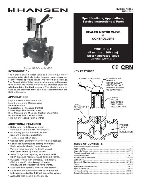
Bulletin <strong>R629g</strong>AUG 2011Specifications, Applications,Service Instructions & PartsSEALED MOTOR VALVE&CONTROLLERS7/32˝ thru 4˝(5 mm thru 100 mm)Motor Operated ValveUS Patent 6,460,567 B1Model HMMV with VPIFINTRODUCTIONThe <strong>Hansen</strong> Sealed Motor Valve is a truly unique motoroperated valve which eliminates the most common concernof other motor operated valves—valve stem seal leakage.The Sealed Motor Valve has no valve stem seal becausethe non-electric rotor is enclosed in a stainless steel canwhich contains the fluid pressure. The electric stator isoutside the stainless steel can, and is isolated from thefluid in the valve.APPLICATIONSLiquid Make-up to AccumulatorLiquid Injection to CompressorsDX EvaporatorsTemperature or Pressure ControlLow or High Side Level ControlSlow Opening and Closing: Suction Stop ValveNo Pressure Drop: Gravity Drain4-20 mA or Floating Point ControlKEY FEATURESHERMETIC HOUSINGDIRECTACTUATION OFV-PORTELECTRONICSPROVIDESTRONG, SLOWOPERATION WITHMINIMAL POWERCONSUMPTIONCANNEDROTORELIMINATESVALVE STEMSEAL LEAKAGEADDITIONAL FEATURES• Relay input or 4-20mA for directconnection to plant PLC or computer.• All moving parts are sealed so thatfrost will not affect operation.• Tight closing Teflon seat.• Canned rotor eliminates valve stem seal leakage.• Controlled opening and closing minimizesliquid velocity shock, “water hammer.”• Valve is more compact and light weightthan other motor operated valves.• Same flanges and spacing as <strong>Hansen</strong> HA4A/HS4A pressure regulators and solenoid valves.• Suitable for use with ammonia, R22, R134a,CO2 (up to 400 psi only) glycol, water,brines, and other approved refrigerants.• Available with optional Power-Close feature.• Valve or remote mounted VPIF Valve PositionIndicator included for 4-20mA controlled valves.• Available with weld-in connections.PRECISELINEARFLOWREGULATIONTABLE OF CONTENTSIntroduction/Specifications.....................................................1-2Applications............................................................................3-5Capacity Tables....................................................................6-14Operation & Electrical..............................................................15Wiring Diagrams................................................................. 16-17Installation Dimensions.......................................................18-19Calibration...............................................................................20Service & Maintenance.......................................................21-23Parts...................................................................................24-25Piping Recommendations................................................... 26-27Valve Controllers................................................................. 28-31Troubleshooting..................................................................32-35Order Information.....................................................................36
TYPICAL APPLICATIONS - HMSV, HMSVC SEALED MOTOR VALVETYPICAL CHILLER APPLICATIONSVPIFVALVE POSITIONINDICATORVALVE LEVEL CONTROLLERMODEL PCML OR PCMLFVPIFVALVE POSITIONINDICATORSHUTDOWN SOLENOIDIN LIEU OF INTEGRALPOWER-CLOSE HMMRCHMMV OR HMMVCSEALED MOTORVALVECUSTOMER SUPPLIEDHANSEN VARI-LEVEL(WITH MOD420) ORTECHNI-LEVEL VLTPCMT OR PCMTFTEMPERATURECONTROLLERSURGE VESSELHMMR OR HMMRC SEALED MOTORVALVE USED IN PLACE OF HANDEXPANSION VALVEPLACE RTD TEMPERATURESENSOR WITHIN 2’ OF OUTLETFOR BEST CONTROLTYPICAL LIQUID INJECTION COOLING FOR SCREW COMPRESSOR APPLICATIONVPIFSEALEDMOTOR VALVECONTROLLED BYCOMPRESSORMANUFACTURER’SPLC OR COMPUTERHMXV, HMXVC,HMMR, HMMRCSEALED MOTOR VALVE<strong>R629g</strong>AUG 20114
HMMV/HMMVC AND HMSV/HMSVC SUCTION VAPOR CAPACITIESR-134a SUCTION VAPOR CAPACITIES, TONSEvap.Temp.PressureDrop3/4˝ 1˝ 1-1/4˝ 1-1/2˝ 2˝ 3˝ 4˝ºF (psi) HMMR HMMV HMMR HMMV HMMR HMMV HMMR HMMV HMMR HMMV HMMR35 HMMVB HMMV HMMR47 HMMVB HMMV.25 0.4 1.3 0.8 2.3 1.1 3.2 2.3 6.7 3.1 9.2 6.9 13 21 9 22 33.50 0.6 1.8 1.1 3.3 1.5 4.6 3.3 10 4.4 13 10 18 29 13 30 461.0 0.9 2.5 1.5 4.6 2.2 6.4 4.6 13 6.3 18 14 26 41 18 43 65US400-402.0 1.2 3.6 2.2 6.5 3.1 9.1 6.5 19 8.9 26 20 37 58 26 61 925 2.0 5.7 3.4 10 4.8 14 10 30 14 41 31 58 92 41 96 14510 2.8 8.0 4.8 15 6.8 20 15 42 20 58 44 82 130 58 136 20615 3.4 10 5.9 18 8.4 25 18 52 24 71 53 – – 71 – –20 3.9 11 6.9 21 10 29 21 60 28 82 62 – – 82 – –.25 0.3 0.7 0.4 1.3 0.6 1.9 1.3 3.9 1.8 5.3 4.0 7.6 12 5.4 13 19.50 0.4 1.1 0.6 1.9 0.9 2.7 1.9 5.5 2.6 7.5 5.7 11 17 7.6 18 271.0 0.5 1.5 0.9 2.7 1.3 3.7 2.7 7.8 3.6 11 8.1 15 24 11 25 382.0 0.7 2.1 1.3 3.8 1.8 5.3 3.8 11 5.1 15 11 22 34 15 36 545 1.1 3.3 2.0 6.0 2.8 8.4 6.0 17 8.1 24 18 34 54 24 57 8510 1.6 4.7 2.8 8.5 4.0 12 8.4 25 11 34 26 48 76 34 80 121.25 0.1 0.4 0.2 0.7 0.3 0.9 0.7 2.0 0.9 2.7 2.0 3.8 6.0 2.7 6.3 10.50 0.2 0.5 0.3 1.0 0.4 1.3 1.0 2.9 1.3 3.8 2.9 5.4 8.5 3.8 8.9 141.0 0.2 0.7 0.4 1.3 0.6 1.8 1.4 4.0 1.8 5.4 4.0 7.6 12 5.4 13 192.0 0.3 1.0 0.6 1.9 0.9 2.6 2.0 5.7 2.6 7.6 5.7 11 17 7.6 18 27Cv 2.2 6.4 3.9 11.7 5.5 16.4 12 35 16 47 35 66 104 47 110 166R-134a SUCTION VAPOR CAPACITIES, KILOWATTSEvap.Temp.PressureDrop20 MM 25 MM 32 MM 40 MM 50 MM 80 MM 100 MMºC (bar) HMMR HMMV HMMR HMMV HMMR HMMV HMMR HMMV HMMR HMMV HMMR35 HMMVB HMMV HMMR47 HMMVB HMMV.02 1.7 5 3 9 4 13 9 27 13 38 28 56 83 38 84 132.04 2.4 7 4 13 6 18 13 39 18 53 39 79 117 54 118 187.08 3 10 6 18 9 26 18 55 25 75 56 111 165 76 168 264METRIC5-20-40.15 5 14 8 25 12 35 25 75 34 103 76 152 226 105 229 362.4 7 23 13 41 19 57 41 122 56 168 124 249 369 171 375 591.6 9 28 17 50 24 70 50 150 68 206 152 305 452 209 459 7241.0 12 36 21 65 30 90 65 194 88 266 197 – – 270 – –1.4 14 43 25 76 36 107 76 229 105 315 233 – – 319 – –.02 0.9 2.7 1.7 5 2.3 7 5 15 7 20 15 30 45 21 45 71.04 1.3 4 2.4 7 3 10 7 21 10 29 21 42 63 29 64 101.08 1.8 5 3 10 5 14 10 30 14 41 30 60 89 41 90 142.15 2.5 7.5 5 14 6 19 14 41 19 56 41 82 122 56 124 195.4 4.0 12 8 23 10 31 22 67 30 91 67 134 199 92 202 318.6 4.9 15 9 28 13 38 27 82 37 112 82 164 244 113 247 390.02 0.5 1 0.8 3 1.2 4 3 8 4 11 8 16 24 11 24 38.04 0.7 2 1.2 4 2 5 4 11 5 15 11 23 34 16 34 54.08 1.0 3 2 5 2 7 5 16 7 22 16 32 47 22 48 76.15 1.3 4 2 7 3 10 7 22 10 30 22 44 65 30 66 104Kv 1.8 5.5 3.3 10 4.7 14 10 30 13.3 40 30 60 89 40 90 142Reduced Capacity V-Ports shown in gray.For best control and modulation, size the SMV valve for both the full load capacity and the minimum load capacity(weekend load). The minimum load capacity should be at least 15% of the full load capacity. The capacity tables areconservative, so it is not necessary to add a safety factor for capacity.Ammonia, R-22 and R-134a capacities assume 86ºF (30ºC) condensing, except -40ºF (-40ºC) assumes +20ºF (-7ºC)liquid (e.g. two stage). R-404 and R-507 assume 95ºF (35ºC) condensing. For overfeed evaporator suction, add 20% tothe evaporator load or use next larger size valve to accommodate liquid volume.<strong>R629g</strong>AUG 20118
HMMV/HMMVC AND HMSV/HMSVC SUCTION VAPOR CAPACITIESR-404 SUCTION VAPOR CAPACITIES, TONSEvap.Temp.PressureDrop3/4˝ 1˝ 1-1/4˝ 1-1/2˝ 2˝ 3˝ 4˝ºF (psi) HMMR HMMV HMMR HMMV HMMR HMMV HMMR HMMV HMMR HMMV HMMR35 HMMVB HMMV HMMR47 HMMVB HMMV.25 0.5 1.4 0.8 2.5 1.2 3.5 2.5 7.4 3.4 9.9 7.5 14 22 10 23 35.50 0.7 2.0 1.2 3.6 1.7 5.0 3.6 11 4.8 14 11 20 32 14 33 501.0 0.9 2.8 1.7 5.0 2.4 7.1 5.1 15 6.7 20 15 28 45 20 47 71400-40R-404 SUCTION VAPOR CAPACITIES, KILOWATTSEvap.Temp.2.0 1.3 3.9 2.4 7.1 3.4 10 7.2 21 9.5 28 21 40 63 28 66 1005 2.1 6.2 3.7 11 5.3 16 11 33 15 44 34 63 100 45 105 15810 3.0 8.7 5.3 16 7.5 22 16 47 21 63 47 89 141 63 148 22415 3.7 11 6.5 19 9.2 27 20 58 26 77 58 – – 78 – –20 4.2 12 7.5 22 11 32 23 66 30 89 67 – – 90 – –.25 0.3 0.8 0.5 1.4 0.7 2.1 1.5 4.2 2.0 6.0 4.4 8.3 13 5.9 14 21.50 0.4 1.2 0.7 2.1 1.0 2.9 2.1 6.0 2.9 8.5 6.2 12 19 8.4 20 301.0 0.6 1.6 1.0 2.9 1.4 4.1 2.9 8.5 4.1 12 8.8 17 26 12 28 422.0 0.8 2.3 1.4 4.1 1.9 5.8 4.1 12 5.8 17 12 23 37 17 39 595 1.3 3.6 2.2 6.5 3.1 9.2 6.5 19 9.2 27 20 37 59 26 62 9310 1.8 5.1 3.1 9.2 4.3 13 9.2 27 13 38 28 53 83 37 87 132.25 0.1 0.4 0.3 0.8 0.4 1.1 0.8 2.3 1.1 3.1 2.4 4.5 7.1 3.1 7.3 11.50 0.2 0.6 0.4 1.1 0.5 1.6 1.1 3.3 1.5 4.5 3.4 6.3 10 4.4 10 161.0 0.3 0.8 0.5 1.6 0.7 2.2 1.6 4.7 2.1 6.3 4.8 9.0 14 6.2 15 222.0 0.4 1.2 0.7 2.2 1.0 3.1 2.3 6.6 3.0 8.9 6.7 13 20 9 21 31Cv 2.2 6.4 3.9 11.7 5.5 16.4 12 35 16 47 35 66 104 47 110 166PressureDrop20 MM 25 MM 32 MM 40 MM 50 MM 80 MM 100 MMºC (bar) HMMR HMMV HMMR HMMV HMMR HMMV HMMR HMMV HMMR HMMV HMMR35 HMMVB HMMV HMMR47 HMMVB HMMV5-20-40.02 1.8 5.5 3.4 10 4.8 14 10 31 14 42 31 62 92 42 93 146.04 2.5 7.7 4.8 14 6.8 20 14 43 20 59 44 87 130 60 131 207.08 3.6 11 6.7 20 9.6 28 20 61 28 83 62 124 183 85 186 293.15 4.9 15 9.2 28 13 39 28 84 38 114 85 169 251 116 254 401.4 8.0 24 15 46 21 64 46 137 62 186 138 276 410 189 415 655.6 9.8 30 18 56 26 78 56 168 76 228 169 338 502 232 508 8021.0 13 39 24 72 34 101 72 217 98 294 218 – – 299 – –1.4 15 46 28 86 40 119 86 257 116 348 258 – – 354 – –.02 1.0 3.1 1.8 5.5 2.6 7.7 5.6 17 7.6 23 17 34 50 23 51 81.04 1.4 4.3 2.6 7.7 3.6 11 7.9 24 11 33 24 48 71 33 72 114.08 2.0 6.1 3.6 11 5.1 15 11 34 15 46 34 68 101 47 102 161.15 2.7 8.4 5.0 15 7.1 21 15 46 21 63 47 93 138 64 140 221.4 4.5 14 8.1 24 12 34 25 75 34 103 76 152 225 104 229 361.6 5.5 17 10 30 14 42 31 92 42 126 93 186 276 128 280 442.02 0.6 1.8 1.0 3.2 1.5 4.4 3.2 9.5 4.4 13 9.6 19 28 13 29 45.6.04 0.8 2.5 1.5 4.5 2.1 6.2 4.5 13 6.2 19 14 27 40 19 41 64.5.08 1.1 3.5 2 6.4 2.9 8.8 6.3 19 8.7 26 19 38 57 26 58 91.3.15 1.6 4.8 3 8.7 4.0 12 8.7 26 12 36 26 53 78 36 79 125Kv 1.8 5.5 3.3 10 4.7 14 10 30 13.3 40 30 60 89 40 90 142US METRICReduced Capacity V-Ports shown in gray.For best control and modulation, size the SMV valve for both the full load capacity and the minimum load capacity(weekend load). The minimum load capacity should be at least 15% of the full load capacity. The capacity tables areconservative, so it is not necessary to add a safety factor for capacity.Ammonia, R-22 and R-134a capacities assume 86ºF (30ºC) condensing, except -40ºF (-40ºC) assumes +20ºF (-7ºC)liquid (e.g. two stage). R-404 and R-507 assume 95ºF (35ºC) condensing. For overfeed evaporator suction, add 20% tothe evaporator load or use next larger size valve to accommodate liquid volume.9<strong>R629g</strong>AUG 2011
HMMV/HMMVC AND HMSV/HMSVC SUCTION VAPOR CAPACITIESR-507 SUCTION VAPOR CAPACITIES, TONSEvap.Temp.PressureDrop3/4˝ 1˝ 1-1/4˝ 1-1/2˝ 2˝ 3˝ 4˝ºF (psi) HMMR HMMV HMMR HMMV HMMR HMMV HMMR HMMV HMMR HMMV HMMR35 HMMVB HMMV HMMR47 HMMVB HMMV.25 0.5 1.4 0.9 2.6 1.2 3.5 2.7 7.8 3.5 10 7.7 15 23 10 24 37.50 0.7 2.0 1.2 3.7 1.7 5.0 3.8 11 4.9 15 11 21 33 15 34 521.0 1.0 2.8 1.7 5.2 2.4 7.1 5.3 16 7.0 21 15 29 46 21 49 74US400-402.0 1.4 4.0 2.4 7.3 3.4 10 7.5 22 9.9 29 22 41 65 29 69 1045 2.2 6.3 3.8 12 5.3 16 12 35 16 46 35 65 103 47 109 16410 3.1 8.9 5.4 16 7.5 22 17 49 22 65 49 92 145 66 154 23315 3.8 11 6.7 20 9.2 27 21 60 27 79 60 _ – 81 – –20 4.3 13 7.7 23 11 32 24 70 31 92 69 – – 93 – –.25 0.3 0.8 0.5 1.6 0.7 2.2 1.6 4.6 2.2 6.4 4.6 8.8 14 6.2 15 22.50 0.4 1.2 0.7 2.2 1.0 3.1 2.2 6.5 3.1 9.0 6.6 12 20 9 21 311.0 0.6 1.7 1.0 3.1 1.4 4.3 3.2 9.2 4.3 13 9.3 18 28 12 29 442.0 0.8 2.4 1.5 4.4 2.0 6.1 4.5 13 6.1 18 13 25 39 18 41 625 1.3 3.8 2.3 7.0 3.2 9.6 7.0 21 9.7 28 21 39 62 28 65 9810 1.8 5.4 3.3 9.8 4.6 14 10 29 14 40 29 55 87 39 92 139.25 0.2 0.5 0.3 0.8 0.4 1.2 0.9 2.5 1.1 3.4 2.5 4.7 7.4 3.3 7.7 12.50 0.2 0.7 0.4 1.2 0.6 1.7 1.2 3.6 1.6 4.8 3.5 6.7 11 4.7 11 171.0 0.3 0.9 0.6 1.7 0.8 2.3 1.7 5.0 2.3 6.7 5.0 9.4 15 6.6 15 232.0 0.4 1.3 0.8 2.4 1.1 3.3 2.4 7.1 3.2 9.5 7.1 13 21 9 22 33Cv 2.2 6.4 3.9 11.7 5.5 16.4 12 35 16 47 35 66 104 47 110 166R-507 SUCTION VAPOR CAPACITIES, KILOWATTSEvap.Temp.PressureDrop20 MM 25 MM 32 MM 40 MM 50 MM 80 MM 100 MMºC (bar) HMMR HMMV HMMR HMMV HMMR HMMV HMMR HMMV HMMR HMMV HMMR35 HMMVB HMMV HMMR47 HMMVB HMMV.02 1.9 5.8 3.5 11 4.9 15 11 32 14 43 32 64 95 44 96 152.04 2.7 8.3 4.9 15 6.9 21 15 45 20 61 45 91 134 62 136 215.08 3.8 12 7.0 21 9.8 29 21 64 29 87 64 128 190 88 193 304METRIC5-20-40.15 5.2 16 9.6 29 13 40 29 87 40 119 88 175 260 120 264 416.4 8.6 26 16 47 22 65 47 142 65 194 143 286 425 196 431 679.6 10 32 19 58 27 80 58 174 79 238 175 351 520 240 527 8321.0 14 41 25 75 35 103 75 225 102 307 226 – – 310 – –1.4 16 49 29 89 41 122 89 266 121 364 268 – – 367 – –.02 1.1 3.2 1.9 5.8 2.8 8.4 6.0 18 8.0 24 18 36 53 25 54 85.04 1.5 4.6 2.7 8.3 4.0 12 8.4 25 11 34 25 51 75 35 76 120.08 2.1 6.5 3.9 12 5.6 17 12 36 16 48 36 72 107 49 108 170.15 2.9 8.9 5.3 16 7.7 23 16 49 22 66 49 98 146 67 148 233.4 4.8 15 8.6 26 13 38 27 80 36 108 80 161 238 110 241 380.6 5.8 18 11 32 15 46 33 98 44 132 98 197 292 135 295 466.02 0.6 1.9 1.1 3.4 1.6 4.7 3.4 10 4.6 14 10 21 31 14 31 49.04 0.9 2.6 1.6 4.8 2.3 6.7 4.8 14 6.5 20 15 29 43 20 44 69.08 1.2 3.7 2.2 6.8 3.2 9.5 6.8 20 9.2 28 21 41 61 28 62 98.15 1.7 5.1 3.1 9.3 4.4 13 9.3 28 13 38 28 57 84 39 85 134Kv 1.8 5.5 3.3 10 4.7 14 10 30 13.3 40 30 60 89 40 90 142Reduced Capacity V-Ports shown in gray.For best control and modulation, size the SMV valve for both the full load capacity and the minimum load capacity(weekend load). The minimum load capacity should be at least 15% of the full load capacity. The capacity tables areconservative, so it is not necessary to add a safety factor for capacity.Ammonia, R-22 and R-134a capacities assume 86ºF (30ºC) condensing, except -40ºF (-40ºC) assumes +20ºF (-7ºC)liquid (e.g. two stage). R-404 and R-507 assume 95ºF (35ºC) condensing. For overfeed evaporator suction, add 20% tothe evaporator load or use next larger size valve to accommodate liquid volume.<strong>R629g</strong>AUG 201110
HMMR/HMMRC AND HMXV/HMXVC LIQUID MAKE-UP AND DIRECT EXPANSION CAPACITIESUS TONSPortSize(IN)ModelNo.RecommendedMinimum Line Size(inches)AmmoniaHalocarbonCvHigh toIntermediateCapacity Range, TonsAmmonia R-22 R-134a R-404 R-507Intermediateto LowHigh toIntermediateIntermediateto LowHigh toIntermediateIntermediateto LowHigh toIntermediateIntermediateto LowHigh toIntermediateIntermediateto Low3/16˝ HMXV/A 3/4˝ 3/4˝ 0.6 73 42 15 10 11 8 11 8 10 81/4˝ HMXV/B 1˝ 1˝ 1.1 133 77 27 18 21 14 19 15 19 153/4˝ HMMR 1-1/2˝ 1-1/2˝ 2.2 266 155 54 37 41 28 39 31 38 301˝ HMMR 2˝ 2˝ 3.9 472 274 97 65 73 49 68 55 67 531-1/4˝ HMMR 2-1/2˝ 2-1/2˝ 5.5 666 387 136 92 104 69 97 77 95 741-1/2˝ HMMRB 2-1/2˝ 3˝ 6.0 726 422 149 100 113 76 105 84 104 811-1/2˝ HMMR 4˝ 4˝ 12 1,453 844 297 200 226 151 211 168 207 1632˝ HMMR 4˝ 4˝ 16 1,937 1,125 396 267 301 202 281 224 277 2173˝ HMMR16 4˝ 4˝ 16 1,937 1,125 396 267 301 202 281 224 277 2173˝ HMMR35 6˝ 6˝ 35 4,237 2,461 867 583 659 441 614 490 605 4744˝ HMMR27 5˝ 6˝ 27 3,268 1,898 669 450 508 340 474 378 467 3664˝ HMMR47 6˝ 8˝ 47 5,689 3,304 1,164 783 885 592 825 658 812 637METRIC KILOWATTSPortSize(mm)ModelNo.RecommendedMinimum Line Size(mm)AmmoniaHalocarbonKvHigh toIntermediateCapacity Range, kWAmmonia R-22 R-134a R-404 R-507Intermediateto LowHigh toIntermediateIntermediateto LowHigh toIntermediateIntermediateto LowHigh toIntermediateIntermediateto LowHigh toIntermediate5 HMXV/A 20 20 0.5 257 148 53 35 39 28 39 28 35 287 HMXV/B 25 25 0.9 468 271 95 63 74 49 67 53 67 5320 HMMR 40 40 1.8 936 545 190 130 144 98 137 109 134 10625 HMMR 50 50 3.3 1660 964 341 229 257 172 239 193 236 18632 HMMR 65 65 4.7 2342 1361 478 324 366 243 341 271 334 26040 HMMRB 65 75 5.0 2553 1484 524 352 397 267 369 295 366 28540 HMMR 100 100 10.0 5110 2968 1045 703 795 531 742 591 728 57350 HMMR 100 100 13.3 6812 3957 1393 939 1059 710 988 788 974 76380 HMMR16 100 100 13.3 6812 3957 1393 939 1059 710 988 788 974 763Intermediateto LowUS METRIC80 HMMR35 150 150 30 14902 8655 3049 2050 2318 1551 2159 1723 2128 1667100 HMMR27 125 150 23 11494 6676 2253 1583 1787 1196 1667 1329 1642 1287100 HMMR47 150 200 40 20008 11620 4094 2754 3113 2082 2902 2314 2856 2240Ammonia line size capacities are based on IIAR Refrigeration Piping Handbook tables. Halocarbon line size capaciitesare based on a nominal 3 ft/sec liquid velocity.For applications with a large pressure drop across the Sealed Motor Valve, attention must be paid to proper outlet linesizing to accommodate flash gas.Ammonia, R-22 and R134a capacities are based on +86°F (+30°C) saturated liquid and +20°F(-10°C) evaporatingtemperature, and intermediate to low capacity based on +20°F (-10°C) saturation temperature and -20°F (-30°C) evaporatingtemperature. Capacities are with ±20% from -40°F (-40°C) to -0°F (-18°C). R404 and R507 capacities based on +95° F(+35°C) condensing temperature.11<strong>R629g</strong>AUG 2011
HMMV/HMMVC AND HMSV/HMSVC HIGH PRESSURE LIQUID LINE CAPACITIESAMMONIA HIGH PRESSURE LIQUID LINE CAPACITIES, TONSPressureDroppsiNominal Size (INCHES)3/4˝ 1˝ 1-1/4˝ 1-1/2˝ 2˝ 3˝ 4˝HMMR HMMV HMMR HMMV HMMR HMMV HMMR HMMV HMMR HMMV HMMR35 HMMVB HMMV HMMR47 HMMVB HMMV1.0 34 98 60 180 85 254 185 539 246 723 539 1,016 1,601 724 1,693 2,5552.0 48 139 85 255 120 359 261 762 348 1,023 762 1,437 2,264 1,023 2,395 3,614Cv 2.2 6.4 3.9 11.7 5.5 16.4 12 35 16 47 35 66 104 47 110 166AMMONIA HIGH PRESSURE LIQUID LINE CAPACITIES, KILOWATTSPressureDropbarNominal Size (MM)20 25 32 40 50 80 100HMMR HMMV HMMR HMMV HMMR HMMV HMMR HMMV HMMR HMMV HMMR35 HMMVB HMMV HMMR47 HMMVB HMMV0.10 139 425 255 773 363 1,082 773 2,318 1,053 3,168 2,344 5,156 6,953 3,212 7,051 11,1250.20 197 601 361 1,093 514 1,530 1,093 3,278 1,490 4,480 3,314 7,292 9,833 4,543 9,972 15,733kv 1.8 5.5 3.3 10 4.7 14 10 30 13.3 40 30 66 89 40 90 142R-22 HIGH PRESSURE LIQUID LINE CAPACITIES, TONSPressureDroppsiNominal Size (INCHES)3/4˝ 1˝ 1-1/4˝ 1-1/2˝ 2˝ 3˝ 4˝HMMR HMMV HMMR HMMV HMMR HMMV HMMR HMMV HMMR HMMV HMMR35 HMMVB HMMV HMMR47 HMMVB HMMV1.0 7.0 21 12 37 18 53 39 113 52 151 113 213 336 152 355 5352.0 10 29 18 53 25 75 55 160 73 214 160 301 475 214 502 757Cv 2.2 6.4 3.9 11.7 5.5 16.4 12 35 16 47 35 66 104 47 110 166R-22 HIGH PRESSURE LIQUID LINE CAPACITIES, KILOWATTSPressureDropbarNominal Size (MM)20 25 32 40 50 80 100HMMR HMMV HMMR HMMV HMMR HMMV HMMR HMMV HMMR HMMV HMMR35 HMMVB HMMV HMMR47 HMMVB HMMV0.10 30 91 54 164 77 230 164 493 218 657 493 1,080 1,460 673 1,480 2,3300.20 42 128 77 232 109 325 232 697 309 929 697 1,540 2,070 952 2,090 3300kv 1.8 5.5 3.3 10 4.7 14 10 30 13.3 40 30 66 89 40 90 142Ammonia, R-22, and R-134a capacities based on +86°F(30°C) saturated liquid, and +20°F (-10°C) evaporator, and noflashing through the valve. R-404 and R-507 based on 95°F(35°C) saturated liquid temperatures.Refer to page 2 for Liquid Line Sizing. Liquid line based on IIAR Piping Handbook Line Size Capacities.<strong>R629g</strong>AUG 201112
R-134a HIGH PRESSURE LIQUID LINE CAPACITIES, TONSPressureDroppsiHMMV/HMMVC AND HMSV/HMSVC HIGH PRESSURE LIQUID LINE CAPACITIESNominal Size (INCHES)3/4˝ 1˝ 1-1/4˝ 1-1/2˝ 2˝ 3˝ 4˝HMMR HMMV HMMR HMMV HMMR HMMV HMMR HMMV HMMR HMMV HMMR35 HMMVB HMMV HMMR47 HMMVB HMMV1.0 7.0 19 12 35 16 49 36 104 47 139 104 196 309 140 327 4932.0 9.0 27 16 49 23 69 50 147 67 197 147 277 437 197 462 697Cv 2.2 6.4 3.9 11.7 5.5 16.4 12 35 16 47 35 66 104 47 110 166R-134a HIGH PRESSURE LIQUID LINE CAPACITIES, KILOWATTSPressureDropbarNominal Size (MM)20 25 32 40 50 80 100HMMR HMMV HMMR HMMV HMMR HMMV HMMR HMMV HMMR HMMV HMMR35 HMMVB HMMV HMMR47 HMMVB HMMV0.10 27 83 50 152 71 213 152 456 202 607 456 1,000 1,350 623 1,370 2,1600.20 39 118 71 215 101 301 215 645 286 859 644 1,418 1,912 881 1,934 3,051kv 1.8 5.5 3.3 10 4.7 14 10 30 13.3 40 30 66 89 40 90 142R-404 HIGH PRESSURE LIQUID LINE CAPACITIES, TONSPressureDroppsiNominal Size (INCHES)3/4˝ 1˝ 1-1/4˝ 1-1/2˝ 2˝ 3˝ 4˝HMMR HMMV HMMR HMMV HMMR HMMV HMMR HMMV HMMR HMMV HMMR35 HMMVB HMMV HMMR47 HMMVB HMMV1.0 4.0 13 8.0 23 11 33 24 69 32 93 69 130 204 92 216 3262.0 6.0 18 11 33 15 46 33 97 45 131 97 183 289 131 305 461Cv 2.2 6.4 3.9 11.7 5.5 16.4 12 35 16 47 35 66 104 47 110 166R-404 HIGH PRESSURE LIQUID LINE CAPACITIES, KILOWATTSPressureDropbarNominal Size (MM)20 25 32 40 50 80 100HMMR HMMV HMMR HMMV HMMR HMMV HMMR HMMV HMMR HMMV HMMR35 HMMVB HMMV HMMR47 HMMVB HMMV0.10 19 57 34 103 48 144 103 310 141 423 313 688 928 431 942 1,4900.20 26 80 48 146 68 204 146 438 199 598 443 974 1,320 610 1,340 2,110kv 1.8 5.5 3.3 10 4.7 14 10 30 13.3 40 30 66 89 40 90 142R-507 HIGH PRESSURE LIQUID LINE CAPACITIES, TONSPressureDroppsiNominal Size (INCHES)3/4˝ 1˝ 1-1/4˝ 1-1/2˝ 2˝ 3˝ 4˝HMMR HMMV HMMR HMMV HMMR HMMV HMMR HMMV HMMR HMMV HMMR35 HMMVB HMMV HMMR47 HMMVB HMMV1.0 4.0 13 8.0 23 11 33 24 69 32 93 69 130 205 92 216 3272.0 6.0 18 11 33 15 46 33 97 45 131 98 184 290 131 306 462Cv 2.2 6.4 3.9 11.7 5.5 16.4 12 35 16 47 35 66 104 47 110 166R-507 HIGH PRESSURE LIQUID LINE CAPACITIES, KILOWATTSPressureDropbarNominal Size (MM)20 25 32 40 50 80 100HMMR HMMV HMMR HMMV HMMR HMMV HMMR HMMV HMMR HMMV HMMR35 HMMVB HMMV HMMR47 HMMVB HMMV0.10 19 57 34 104 49 145 104 311 142 426 313 688 928 429 941 1,4900.20 27 81 49 147 69 205 147 440 200 602 443 974 1,310 607 1,330 2,100kv 1.8 5.5 3.3 10 4.7 14 10 30 13.3 40 30 66 89 40 90 142Ammonia, R-22, and R-134a capacities based on +86°F(30°C) saturated liquid, and +20°F (-10°C) evaporator, and noflashing through the valve. R-404 and R-507 based on 95°F(35°C) saturated liquid temperatures.Refer to page 2 for Liquid Line Sizing. Liquid line based on IIAR Piping Handbook Line Size Capacities.13<strong>R629g</strong>AUG 2011
HMMV/HMMVC AND HMSV/HMSVC HOT GAS SOLENOID DEFROST CAPACITIESEVAPORATOR SIZE IN TONS (kW)Refrigerant3/4˝(20)1˝(25)Nominal Size (MM)1-1/4˝(32)1-1/2˝(40)2˝(50)AmmoniaR-22R-134aR-404R-5079-15(32-53)6-8(21-28)1-4(4-14)3-6(11-22)1-4(4-14)15-28(53-99)8-15(28-53)4-8(14-28)6-10(22-35)4-8(14-28)28-39(99-137)15-20(53-70)8-12(28-42)10-18(35-63)8-12(28-42)39-73(137-256)20-32(70-113)12-20(42-70)18-30(63-106)12-20(42-70)73-106(256-373)32-47(113-165)20-38(70-134)30-44(106-155)20-38(70-134)Evaporator tons at 10ºF temperature differential, valve capacities are conservative.<strong>R629g</strong>AUG 201114
OPERATION: HMMV AND HMMRThe motor shaft is coupled to a threaded stem whichdirectly drives the valve V-port open or closed. The valveis driven by motor windings and electronics placed outsideof a hermetic can and hermetically sealed in a liquid tighthousing. Inside the can is a motor rotor which drives themotor shaft.Please note that Sealed Motor Valves 2˝ and smaller willoperate and seal with flow in either direction. 3˝ and 4˝pressure assisted Sealed Motor Valves will only operateand seal with inlet equal to or greater than outlet pressure.Where pressure reversals are expected, a check valve atthe outlet of the 3˝ and 4˝ SMV is recommended.The HMMV and HMMR valve are electronically operatedby 7 wires. Two wires provide 24 VAC to power the motor.Two wires provide a 4-20 mA input to control the openingand closing of the valve. Two additional wires provide4-20 mA feedback of actual valve V-port position. Thefeedback does not have to be connected to operate thevalve. The 7th wire is a ground wire.A 4-20 mA control signal must always be maintained tokeep the V-port in position. Loss of 4-20mA signal willdrive the valve closed. When driven fully closed or fullyopen the motor will shut off. Likewise, the motor will shutoff when the V-port has reached the position indicated bythe 4-20mA input signal. If loss of 24 VAC power occurs,the valve remains in its current position, unless the valveis equipped with Power-Close.The valve is programmed to close when the signal is lessthan 4.8 mA (Less than 5% flow). This is to minimize seaterosion during low load conditions.POWER-CLOSE OPTIONSModels HMMVC, HMMRC, HMXVC, and HMSVC have anintegral capacitor storage to power the valve closed inthe event of loss of 24 VAC power.VPIF VALVE POSITION INDICATORThe Valve Position Indicator,model VPIF is a digitalmonitoring module addedto the standard SealedMotor Valve (SMV) productline. The VPIF monitors thevalve position during normaloperation and is used torecalibrate the valve afterservice work is performed.The large LED displayallows for viewing ofthe valve position (inpercent) during normaloperation. The VPIF contains an internal independent4 mA and 20 mA current source, which is switch selectablefor recalibration at the valve 0% 4 mA (closed) positionand 100% 20 mA (full open) position.The VPIF can be mounted on or near the valve for easeof use and visibility of the display. Often, valves aremounted high in the air or in obstructive areas where thetechnician cannot easily reach. The VPIF can be mountedup to 10 feet (3 meters) in any direction from the valve.VPIEC Extension Cables are available where more lengthis required.15ADVANTAGES OF VPIF WITH SMVIn the normal operating mode the VPIF passes the 4 to 20mA current loop signals and 24V AC to and from the SMVwithout signal degradation. When used for recalibration,the VPIF will output either 4 mA (fully closed) or 20mA (fully open). A waterproof 3-position switch on theoutside of the VPIF enclosure is used for recalibrationof the SMV. The switch in the up position produces20 mA; the switch in the down position produces a 4 mAsignal to the valve. The calibration key must be attached tothe designated location on the side of the SMV powerheadin order for the valve to recalibrate. After recalibration,return the switch to the middle position (automatic) andremove calibration key.The VPIF valve position feedback can alert operators tovalves controlled by an unstable control scheme. Thisfeature is very important to the proper operation of therefrigeration system and the life of the Sealed Motor Valve.The VPIF is compact and reliable at very low temperatures.Waterproof quick disconnect connectors allow for easyremoval of the SMV power head for service.See Bulletin VPIF for complete details on the Valve PositionIndicator.OPERATION: HMSVThe HMSV motor operates on 24 VAC. (Valves built beforeJanuary 1, 2005 use 28 VDC power supply.) Electronicsinside the stator housing pulse power to the motor toprovide strong, slow opening and closing operation withminimal wattage.The HMSV valve is electrically operated by three wiresplus ground. Two wires provide 24 VAC input, and a thirdis signal, which commands the valve to either open orclose. Electrically connecting the signal wire (3) to 24VAC input wire (1) will drive the valve open. Electricallyconnecting the signal wire (3) to 24 VAC input wire (2)will drive the valve closed. If the signal wire (3) is notconnected to either 24 VAC signal wires, the valve willremain in its last position. (Also, on loss of power thevalve will remain at its last position.) If Power-Close isrequired, specify model HMSVC.The locked rotor amperage is not significantly higher thanthe running amperage; therefore, continuing to supplypower to the motor after it has fully opened or closed(stalled) is acceptable and typical for the HMSV valve. Thepower supply and wiring must be sized for a 90 W peakpulsed load. However, average power consumed is 10 W.Since the motor consumes minimal wattage, electricalcosts and overheating are not concerns.<strong>R629g</strong>AUG 2011
HMMV/HMMVC, HMXV/HMXVC, AND HMMR/HMMRC WIRING DIAGRAMCUSTOMER SUPPLIED POWER SUPPLY AND CONTROLLER(Modulating Control with Position Feedback)The valve is supplied with 10 feet of cable with 18 gauge wires. For greater distance between valve and controller usewire size as shown in Table 1: 24VAC Power Wiring. Do not run Sealed Motor Valve wiring with or near high voltagepower wiring or VFD Controls (Variable Frequency Drives). Do not earth or ground 24 VAC wiring.TABLE 1: 24VAC POWER WIRING24VAC POWER WIRING(WIRES NO. 1 AND 2)(90VA PER VALVE REQUIRED)AWG WIRE GAUGE (MM 2 )NUMBER OF VALVES POWEREDCABLE LENGTH, FT(M) 1 2 3 450 (15) 18 (1,0) 16 (1,5) 14 (2,5) 12 (4,0)100 (30) 16 (1,5) 12 (4,0) 10 (6,0) 10 (6,0)150 (46) 12 (2,5) 10 (6,0) 8 (10,0) 8 (10,0)200 (61) 12 (4,0) 10 (6,0) 8 (10,0)CUSTOMER SUPPLIEDLINE VOLTAGE300 (91) 10 (6,0) 8 (10,0)VPIFVALVE POSITION INDICATORTRANSFORMER24VAC90VA MINPER VALVEDC POWERSUPPLY 24VDC50MA MIN PERVALVEISOLATED FROM EARTH GROUNDYELLOW/GREEN STRIPE(GROUND)1 24VAC(POWER)2 24VAC(POWER)3 – 4-20MA INPUT (CONTROL SIGNAL)COMPUTERORCONTROLLER456+ 4-20MA INPUT (CONTROL SIGNAL)– 4-20MA OUTPUT (VALVE POSITION FB)+ 4-20MA OUTPUT (VALVE POSITION FB)THE VALVE IS SUPPLIED WITH 10’ OF CABLE WITH 18GAUGE WIRES. FOR GREATER DISTANCE BETWEENVALVE AND CONTROLLER, OR MULTIPLE VALVEINSTALLATIONS, USE WIRE SIZE AS SHOWN IN TABLE1: 24 VAC POWER WIRING. DO NOT RUN SEALEDMOTOR VALVE WIRING WITH OR NEAR POWERWIRING.APPLICATION EXAMPLE: CORRECT4 VALVES POWERED BY ONE TRANSFORMER(100 Feet Between Transformer & Valves)APPLICATION EXAMPLE: INCORRECT4 VALVES POWERED BY ONE TRANSFORMER(Wire Size Too Small – Grounded Neutral)<strong>R629g</strong>AUG 201116
HMSV AND HMSVC WIRING DIAGRAMCUSTOMER SUPPLIED POWER SUPPLY AND CONTROLLER(Slow Opening and Closing Applications)TYPICAL APPLICATIONSIDEAL FOR REPLACEMENT OF:1. BOTH HOT GAS SOLENOID VALVEAND SOFT GAS SOLENOID VALVEWITH A SINGLE HANSEN SEALEDMOTOR VALVE.CUSTOMER SUPPLIEDLINE VOLTAGE2. BOTH SUCTION SOLENOID VALVEAND EQUALIZE SOLENOID VALVEWITH A SINGLE HANSEN SEALEDMOTOR VALVE.115VACNEUTRAL3. ANY OPEN/CLOSED APPLICATIONREQUIRING SLOW OPERATION TOMINIMIZE LIQUID VELOCITY SHOCKAND/OR REQUIRING NO PRESSUREDROP TO OPERATE. (VENT OR GRAVITY DRAIN)4. MOST MOTORIZED BALL VALVE ANDBUTTERFLY VALVE APPLICATIONS THEREBYELIMINATING SHAFT SEAL LEAKAGE.ISOLATED FROM EARTH GROUNDYELLOW/GREEN STRIPE1 24 VAC24 VACPOWERSUPPLY90WMINIMUMCONTROLLEROPEN2 24 VACCLOSE3SIGNALHANSENTHE VALVE IS SUPPLIED WITH 10 FEET OF CABLEWITH 18 GAGE WIRES. FOR GREATER DISTANCEBETWEEN VALVE AND CONTROLLER, OR MULTIPLEVALVE INSTALLATIONS, USE WIRE SIZEAS SHOWN IN TABLE 1. DO NOT RUN SEALED MOTORVALVE WIRING WITH OR NEAR POWER WIRING24VAC POWER WIRING2AWG WIRE GAGE (mm)(WIRES NO. 1 AND 2)(90VA PER VALVE REQUIRED)NUMBER OF VALVES POWEREDVALVE WILL OPEN ORCLOSE DEPENDING ONWHICH CONTACT ISCLOSED. VALVE WILLREMAIN AT ITS LASTPOSITIONS WHEN BOTHCONTACTS ARE OPEN.HANSEN SEALED MOTOR VALVEHMSV/HMSVCCABLE LENGTH, ft (m)50 (15)100 (30)1 2 3 418 (1,0) 16 (1,5) 14 (2,5) 12 (4,0)16 (1,5) 12 (4,0) 10 (6,0) 10 (5,5)150 (46)300 (91)(WIRES NO. 1 AND 2)(90VA PER VALVE REQUIRED)14 (2,5) 10 (6,0) 8 (8,5) 8 (8,5)TABLE 1: 24VAC POWER WIRING200 (61)12 (4,0) 10 (6,0) 8 (8,5)24VAC POWER WIRING AWG WIRE GAUGE (MM 2 )10 (6,0) 8 (8,5)NUMBER OF VALVES POWEREDCABLE LENGTH, FT(M) 1 2 3 450 (15) 18 (1,0) 16 (1,5) 14 (2,5) 12 (4,0)100 (30) 16 (1,5) 12 (4,0) 10 (6,0) 10 (6,0)150 (46) 12 (2,5) 10 (6,0) 8 (10,0) 8 (10,0)200 (61) 12 (4,0) 10 (6,0) 8 (10,0)300 (91) 10 (6,0) 8 (10,0)17<strong>R629g</strong>AUG 2011
HMXV, HMXVC MOTORIZED EXPANSION VALVEINSTALLATION DIMENSIONS, INCHES (MM)3/4˝ (20mm) THRU 1-1/4˝ (32mm) SMVALLOW 6.0" (152)FOR REMOVAL OFMOTOR STATORALLOW 6.00" (152mm)FOR REMOVAL OFMOTOR STATOR3/4" NPTCABLEPROTECTOR11.7"(297)VPIF WITH 4-20mAVALVE ONLY12.75"(324)2.11"(54)1.60"(41)3.34"(85)4.19"(106)4.95" (117)FPT, SW4.25 (108) =MAX WIDTHOF VALVE6.19"(157)7.20"(183)4.74" (120) =MAX WIDTHOF VALVE8.94" (227)WN, ODS8.20" (208)FPT, SWINSTALLATIONProtect the interior of valve from dirt and moisture duringstorage and installation. Valve should be installed sothat the arrow on the valve body is in direction of normalrefrigerant flow.Please note: Valve will not backflow if in closed position.Do not install check valves upstream of the Sealed MotorValve without hydrostatic pressure relief. Do not closethe hand valve on inlet or outlet without making sure valveis in the open position. System should be free from dirt,weld slag and rust particles. A 60 mesh, close-coupledstrainer is available for installation at inlet of valve for3/4˝, 1˝ and 1-1/4˝. Do not close-couple strainers to 1-1/2˝through 4˝ Sealed Motor Valves.1/4˝ NPT Gauge/Purge port connections are provided onthe inlet and outlet of the 3/4˝ thru 4˝ valves.Please note: Sealed Motor Valves 2˝ and smaller willoperate and seal with flow in either direction. 3˝ and 4˝pressure assisted Sealed Motor Valves will only operateand seal with inlet equal to or greater than outlet pressure.Where pressure reversals are expected, a check valve atthe outlet of the 3˝ and 4˝ SMV is recommended.<strong>R629g</strong>AUG 201118Pipe sizing, valve placement, rating, anchoring, and similarprudent precautions should be taken to ensure “liquidhammer” will not occur when valves open or close.For proper flange gasket sealing, care must be taken whenthreading or welding to assure flanges are parallel to eachother and perpendicular to pipe. Also, gaskets should belightly oiled and all bolts must be tightened evenly.Protect cable during installation.Do not mount the valve with the motor in the down position.The valve will only operate properly if the motor is mountedin a horizontal or upright position. Refer to diagramsbelow. Horizontal mounting of motor is satisfactory if oiland dirt are controlled.YESNO
INSTALLATION DIMENSIONS, INCHES (MM)1-1/2˝ (40mm) THRU 4˝ (100mm) SEALED MOTOR VALVEALLOW 6.00˝ (152)FOR REMOVAL OFMOTOR STATORVPIF WITH 4-20MAVALVE ONLYABCDESIZE(MM)1-1/2˝ – 2˝(40 – 50)3˝(80)4˝(100)AHMMVHMMRHMSVHMMVCHMMRC12.00(305)14.00(356)13.38(340)15.38(391)14.00(356)16.00(406)B3.00(76)4.00(102)4.75(121)C9.88(251)12.25(311)14.12(359)D10.89(277)13.38(340)15.01(381)ESW12.39(315)15.38(391)17.01(432)EWN, ODS13.39(340)16.40(417)20.51(521)EWELD-IN-LINE10.38(264)12.25(311)14.12(359)MAXWIDTH4.58(117)6.50(166)8.06(205)19<strong>R629g</strong>AUG 2011
RE-CALIBRATION INSTRUCTIONS FORHMMV, HMMR, HMXV, HMMVC, HMMRC,AND HMXVC*<strong>Hansen</strong> Sealed Motor Valves are factory calibrated, andhold their calibration during shipment, power outages,etc. Valve disassembly or manual opening with the MOVT(Manual Operation Valve Tool) does require subsequentrecalibration, therefore after removing or replacing the4-20 mA motor of a Sealed Motor Valve, recalibrate thevalve. Recalibration synchronizes the control input withthe valve position; that means, for example, a 12 mA input(50%) would result in the valve moving to the half-openposition.Recalibration requires the ability to control the 4-20mA control input to the motor between four and twentymilliamps, and requires the ability to allow the valve tostroke fully open and closed. For valves shipped afterJuly 4, 2006, or retrofitted valves with VPIF, the 4 mAand 20 mA signal to calibrate the valve is part of thefunction of the VPIF. If the valve is not equipped with aVPIF, then the 4 mA and 20 mA to calibrate must comefrom the computer or separate signal generator. Onlyqualified refrigeration service personnel should performthis procedure, and proper precautions taken to preventa hazardous or undesirable occurrence resulting fromoperating the valve from open and closed.1. Secure the refrigeration system to allow the valveto open and close fully without causing undesirablesystem problems to occur.2. Mount and secure the motor on the sealed motorvalve. Connect electrical wiring in accordance to thevalve and controller manufacturers specifications.3. Install “Calibration Key” over ‘X’ on side of motorand secure with strap.4. Increase the control input to 20 mA or slightly greater.Move VPIF switch to up position. Maintain at least 20mA for at least two minutes. This will give the valvetime to move to the wide open position and calibrateits position. Note: some computer control systemshave lag times before the control input is sent to thevalve. (Using “System Feedback Mode”).5. Decrease the control input to 4 mA or less. MoveVPIF switch to down position. Maintain 4 mA or lessfor at least two minutes. This will give the valvetime to move to the completely closed position andcalibrate its zero point.6. Again increase the control input to at least 20 mA.Move VPIF switch to up position. Maintain at least20 mA for at least two minutes. This will give thevalve time to move to the wide open position andset its span.7. The valve should now be calibrated and in the wideopen position.8. Remove “Calibration Key” and store. The valve willoperate satisfactorily if the “Calibration Key” remainsover the “X”, but the valve will recalibrate each timethe control input is at 4 mA or 20 mA for more thanthe two minutes.9. Return control system to automatic operation. PlaceVPIF switch in middle position.ELECTRICAL MAINTENANCECheck calibration and Power-Close function on a routinebasis. Check controller and controller wiring for corrosion.Check controller function.MANUAL OPERATION VALVE TOOLUse of the MOVT requires the removal of the power head.Do not remove the bonnet. Use extreme caution whenloosening the power head screws, as the motor maycontain refrigerant under pressure if a breach of the motorcan has occurred (even after system evacuation). Wearprotective gear and look/listen for escaping refrigerantwhile carefully loosening housing screws, and breakingthe pressure seal.Remove housing and place MOVT over can. Manuallyoperate the valve open or closed by turning the MOVT inthe directions indicated on the top of the tool. Refer toTable 2: Number of Turns to Actuate Valve for number ofturns to fully actuate valve. Upon re-installing the powerhead, recalibrate according to instructions.*The HMSV series do not require recalibration.NOTE:Powerhead must be sealed and torqued to 15 foot lbs toprevent moisture from damaging electronics. Care mustbe taken not to damage or dent the can. This will makethe motor inoperative.TABLE 2: NUMBER OF TURNS TO ACTUATE VALVENOMINAL SIZEINCH(MM)NUMBEROF TURNS7/32˝ (5) 69/32˝ (7) 63/4˝- 1-1/4˝ (20 - 32) 71-1/2˝- 2˝ (40 - 50) 123˝ (80) 184˝ (100) 20<strong>R629g</strong>AUG 201120
SERVICE AND MAINTENANCEHMXV SEALED MOTOR VALVE3/4" NPTPROTECTORPOWER HEADCARBON BEARINGROTORCAN3-3/8" O.D.GRAY GASKETGREEN GASKETBONNETSEATCARTRIDGEASSEMBLYBODYINTERNAL STRAINERCARTRIDGE SCREWSO-RINGSBUSHINGNEEDLEASSEMBLY(V-PORT)HMXV DISASSEMBLY1. Isolate the valve from the refrigerant pressure andevacuate the refrigerant.2. During normal circumstances the Power Head (1) isisolated from the refrigerant pressure. If abnormalconditions cause a breach in the isolating Can (5),refrigerant pressure will enter and be contained bythe power head, possibly even after the valve hasbeen isolated and evacuated of refrigerant. Alwaysuse caution when loosening the Power Head (1).Carefully loosen but do not remove the small powerhead screws and break the pressure seal. Observefor signs of internal pressure. After confirming nointernal pressure is present, remove the bolts andthe housing.3. Carefully loosen the larger bonnet bolts, break gasketseal, and if no pressure is present remove the boltsand bonnet. To prevent damage to the can, reinstallPower Head (or MOVT).4. Remove the isolating can (5).5. Remove the two cartridge screws on underside ofbody. Lift off cartridge assembly from body.6. Remove needle assembly by rotating rotorcounterclockwise.21HMXV REASSEMBLY1. Install needle assembly by aligning with rotor andturning rotor clockwise. Align pin of needle assemblywith grooves in keyway bushing.2. Replace gasket into groove in cartridge.3. Replace cartridge assembly with care not to mar thebody seat with end of needle. Replace two cartridgescrews and torque to 35 ft-lbf (47 N-m).4. Install o-ring onto face groove of cartridge. Checkcarbon bearing inside can and install can over rotor.Place green gasket over can (Important that o-ring isbelow can flange and seated properly in groove, andgreen gasket is above can flange to seal betweencan and bonnet).5. Install bonnet over can. Before torquing large bonnetbolts, install 3 3/8˝ OD gray gasket, loosely installmotor housing to prevent wrenching damage to can.Install large bonnet bolts and torque evenly to 35ft-lbf (47 N-m). Install small motor housing screwsand torque evenly to 15 ft-lbf (20 N-m).6. Failure to seal Power Head may result in motor failuredue to moisture damage.<strong>R629g</strong>AUG 2011
SERVICE AND MAINTENANCE3/4˝ (20mm) THRU 2˝ (50mm) SEALED MOTOR VALVE3/4˝ NPTCABLE PROTECTORPOWER HEADCARBON BEARINGROTORCAN3-3/8˝ OD GRAY GASKETCARTRIDGE ASSEMBLY(INCLUDES ROTOR)BONNETGREEN GASKETO-RINGSMALL GRAY GASKETGUIDE PINV-PORTPUMP OUT/GAUGE PORTS3/4˝ - 1¼˝ SHOWN)VALVE DISASSEMBLY 3/4˝ THRU 2˝1. Isolate the valve from the refrigerant pressure andevacuate the refrigerant.2. During normal circumstances the Power Head (1) isisolated from the refrigerant pressure. If abnormalconditions cause a breach in the isolating Can (5),refrigerant pressure will enter and be contained bythe power head, possibly even after the valve hasbeen isolated and evacuated of refrigerant. Alwaysuse caution when loosening the Power Head (1).Carefully loosen but do not remove the small powerhead screws and break the pressure seal. Observefor signs of internal pressure. After confirming nointernal pressure is present, remove the bolts andthe housing.3. Carefully loosen the larger bonnet bolts, break gasketseal, and if no pressure is present remove the boltsand bonnet. To prevent damage to the can, reinstallPower Head (or MOVT).4. Remove the isolating Can (5).5. Grasp the Rotor Magnets (3) and while lifting outsquarely, remove the cartridge assembly, takingcare not to bend the rotor shaft. If cartridgeremoval is difficult, remove by screwing the rotorcounterclockwise and the cartridge will press out.WARNING: Don’t bend shaft.6. Remove the V-port (2) from the cartridge assemblyby unscrewing the rotor counterclockwise.VALVE REASSEMBLY 3/4˝ THRU 2˝1. Inspect all V-port seals for damage. Install V-port intocartridge fully supporting the v-port and cartridgewhile carefully aligning the threaded shaft of cartridgewith the low friction nut of V-port. Carefully threadtogether 6-8 turns, and align the anti-rotation slot onthe V-port with the anti-rotation pin of the cartridge.Fully thread the V-port into the cartridge, screwingthe V-port fully into the cartridge by turning the rotorclockwise.2. Place smaller gray gasket, then cartridge into thebody. Install o-ring onto face groove of cartridge.Check carbon bearing inside can and install canover rotor. Place green gasket over can (Importantthat o-ring is below can flange and seated properlyin groove, and green gasket is above can flange toseal between can and bonnet).3. Install bonnet over can. Before torquing large bonnetbolts, install 3 3/8˝ OD gray gasket, loosely installmotor housing (or MOVT) to prevent wrenchingdamage to can. Install large bonnet bolts and torqueevenly to 35 ft-lbf (47 N-m). Install small motorhousing screws and torque evenly to 15 ft-lbf (20N-m).4. Failure to seal Power Head may result in motor failuredue to moisture damage.<strong>R629g</strong>AUG 201122
SERVICE AND MAINTENANCE3˝ (80mm) & 4˝ (100mm) HMMV SHOCK RESISTANT SEALED MOTOR VALVEFOR SUCTION LINE APPLICATIONS*3/4˝ NPTCARBON BEARINGCABLE PROTECTORPOWER HEADROTORCARTRIDGE ASSEMBLY(INCLUDES ROTOR)GREEN GASKETSMALL GRAY GASKETPISTON SEALSPUMP OUT/GAUGE PORTV-PORTCAN3-3/8˝ OD GRAY GASKETBONNETADAPTER RINGO-RINGGUIDE PINPILOT BODYPILOT SPRINGPOPPET BODYPOPPET SEATPUMP OUT/GAUGE PORTMAIN SPRINGVALVE DISASSEMBLY 3˝ THRU 4˝1. Isolate the valve from the refrigerant pressure andevacuate the refrigerant.2. During normal circumstances the power head (1) isisolated from the refrigerant pressure. If abnormalconditions cause a breach in the isolating Can (5),refrigerant pressure will enter and be contained bythe Power Head, possibly even after the valve hasbeen isolated and evacuated of refrigerant. Alwaysuse caution when loosening the Power Head (1).Carefully loosen but do not remove the small powerhead screws and break the pressure seal. Observefor signs of internal pressure. After confirming nointernal pressure is present, remove the bolts andthe power head.3. Carefully loosen the larger bonnet bolts, break gasketseal, and if no pressure is present remove the boltsand bonnet. To prevent damage to the can, reinstallPower Head (or MOVT).4. Remove the isolating Can (5).5. Grasp the Rotor Magnets (3) and remove the cartridgeassembly by lifting the cartridge assembly from thevalve. Unscrewing the rotor counter-clockwise willaid removal if removal is difficult.6. Remove the adapter plate. Plate can be pried off withslip joint pliers or wrench inserted into center hole.7. Remove the V-port (2) from the body. The bonnetbolts can be screwed into the top of the V-port toaid V-port removal or installation.8. Remove main spring from body.23VALVE REASSEMBLY 3˝ THRU 4˝1. Install main spring into body.2. Inspect all V-port seals for damage. Install V-portassembly into body using care not to damage pistonseals. Main spring fits over pilot seat flange on bottomface of V-port. Place large gasket, then adapterplate onto body. Push down and hold adapter platein position.3. Place smaller gray gasket into counterbore of adapterplate. Install cartridge into body atop the adapterplate.4. Install o-ring onto face groove of cartridge. Checkcarbon bearing inside can and install can over rotor.Place green gasket over can (Important that o-ring isbelow can flange and seated properly in groove, andgreen gasket is above can flange to seal betweencan and bonnet).5. Install bonnet over can. Before torquing large bonnetbolts, install 3-3/8˝ OD gray gasket, loosely installmotor housing (or MOVT) to prevent wrenching damageto can. Install large bonnet bolts and torque evenlyto 175 ft-lbf (237 N-m). Install small motor housingscrews and torque evenly to 15 ft-lbf (20 N-m).*NOTE: Models identified as HMMV/7A and HMMV/8A.For servicing 3˝ and 4˝ Non-Shock Resistant Sealed Motor Valves(model numbers HMMV/7, HMMV/8, HMMR/7, HMMR/8, HMSV/7and HMSV/8) refer to Bulletin R629b.<strong>R629g</strong>AUG 2011
SEALED MOTOR VALVE PARTS LIST3˝ (80mm) & 4˝ (100mm) HMMV, HMMVB & HMSV SHOCK RESISTANT SEALED MOTOR VALVE**NOTE: For servicing 3˝ and 4˝ Non-ShockResistant Sealed Motor Valves (modelnumbers HMMV/7, HMMV/8, HMMR/7,HMMR/8, HMSV/7 and HMSV/8) refer toBulletin R629b.POWER HEAD KIT15 CAN KITCARTRIDGE KIT34 GASKET KITV-PORT KIT23˝ (80mm) & 4˝ (100mm) HMMR SEALED MOTOR VALVE FOR HIGH PRESSURE DROP APPLICATIONS3/4˝ NPTCARBON BEARINGCABLE PROTECTORCAN3-3/8˝ OD GRAY GASKETPOWER HEADROTORCARTRIDGE ASSEMBLY(INCLUDES ROTOR)GREEN GASKETCARTRIDGEREDUCED CAPACITY SPOOLV-PORTPUMP OUT/GAGE PORTBONNETGASKETSO-RINGGUIDE PINO-RINGPUMP OUT/GAGE PORT<strong>R629g</strong>AUG 201124
HMXV SEALED MOTOR VALVESEALED MOTOR VALVE PARTS LIST3/4˝(20mm) - 2˝(50mm) HMMV, HMMR & HMSVSEALED MOTOR VALVEPOWER POWER HEAD KIT1POWER HEAD KIT 1CARTRIDGE KIT35CAN KIT KITCARTRIDGE KIT35CAN KIT4GASKET KIT4GASKET KIT KIT2SEATV-PORT KITV-PORT/SEAT KIT2SEATV-PORT KITINTERNAL STRAINERPART NUMBER PART NUMBER 78-0072VALVE TYPEHMXVNOMINAL SIZEINCH (MM)1 2 3 4 5POWER HEAD KITSEAT/ V-PORT*ASSEMBLY KITSTANDARD POWER-CLOSE P/N Cv7/32˝ (5) For Valves For Valves 75-1176 -9/32˝ (7) with VPIFwith VPIF 75-1179 -3/4˝ (20)order:order:75-1154 6.41˝ (25) 75-1155 11.7HMMV 1 1/4˝ (32) 75-1156 16.41 1/2˝2˝(40)(50)75-1209Power Head75-1212Power Head75-115775-11663547HMMV 3˝ (80)with 2´with 2´75-1197 104cable and cable andHMMVB 3˝ (80) connector connector 75-1223 66HMMV 4˝ (100) 75-1199 166HMMVB 4˝ (100) 75-1224 1103/4˝ (20) 75-1160 2.2For valves For valvesHMMR 1˝ (25) 75-1161 3.9without VPIF without VPIF1 1/4˝ (32) order:order: 75-1154 5.5HMMRB 1 1/2˝ (40) 75-1230 6.01 1/2˝ (40) 75-1162 12HMMR2˝ (50) 75-1163 1675-117175-1183HMMR16 3˝ (80) 75-1268 16Power Head Power HeadHMMR35 3˝ (80) with 10´with 10´ 75-1267 35cablecableHMMR27 4˝ (100) includesincludes 75-1270 35HMMR47 4˝ (100) connector connector 75-1271 47HMSV3/4˝ (20)75-1154 -1˝ (25) 75-1155 -1 1/4˝ (32) 75-1156 -1 1/2˝ (40) 75-1187 75-1184 75-1157 -2˝ (50) 75-1166 -CARTRIDGE*ASSEMBLY KITCAN KIT*GASKET KIT75-1178 75-1177 75-118075-116775-114875-1168 75-115075-292275-1200 75-115175-1201 75-115275-116775-114875-1168 75-115075-292275-1168 75-127275-116775-114875-292275-1168 75-11503˝ (80) 75-1197 - 75-1200 75-11514˝ (100) 75-1199 - 75-1201 75-1152* CARTRIDGE ASSEMBLY KIT, CAN KIT AND SEAT/V-PORT KIT INCLUDE GASKET KIT (Column 5)NOTE: For 3˝ (80mm) and 4˝ (100mm) with model numbers HMMV/7, HMMR/7, HMMV/8, HMMR/8 both V-Port Cartridge Kit and CartridgeKit must be replaced together with Shock Resistant components listed above.** POWER HEAD KITS INCLUDE REPLACEMENT GASKET AND SCREWSPOWER HEAD KIT - CONDUITWhen Power Head cable is installed in conduit, order Standard Power Head Kit 75-1215, cable length is 10´ (3 meters).25<strong>R629g</strong>AUG 2011
SEALED MOTOR VALVE RECOMMENDED PIPINGFIGURE 1: LIQUID FEED VALVE FROM INTERMEDIATE TO LOW TEMPERATURE VESSELFLASH GAS COLLECTION AREAPINTERMEDIATE TEMPERATURELOW TEMPERATURENOT RECOMMENDEDMOUNT CONTROL VALVE CLOSE TOHIGHER PRESSURE VESSELINTERMEDIATE TEMPERATURELOW TEMPERATURERECOMMENDED<strong>R629g</strong>AUG 201126
SEALED MOTOR VALVE RECOMMENDED PIPINGFIGURE 2: PIPING RECOMMENDATIONSLIQUID INLIQUID FALLING CREATINGGAS BUBBLES AT EXIT TOVALVEVORTEXNOT RECOMMENDEDDEFLECT LIQUID TODEFLECT LIQUID TOMINIMIZED MINIMIZED BUBBLES BUBBLESIN LIQUID IN LIQUIDDEFLECTOR PLATE PLATELIQUID INANTI-VORTEXANTI-VORTEXPLATEPLATE1´ 1' (.3M) (.3m)1´ (.3M) 1' (.3m)RECOMMENDED27<strong>R629g</strong>AUG 2011
PCML, PCMLFPCMLF CONTROLLERWIRING DIAGRAMFOR HANSEN PCMLF LIQUIDLEVEL CONTROLLER<strong>Hansen</strong> stand-alone liquid level controllers are suitablefor applications where computer control is either notdesired or not available. Both controllers have builtin24v DC power supply for the 4-20 mA valve positionfeedback loop and the 4-20 mA level control loop. Referto application examples on page 3. No external 24V DCpower supplies are required.LIQUID LEVEL %00actualset pointHANSEN CONTROLLERSSETTING THE CONTROLLER1. In automatic mode, the actual liquid level is displayedin the upper most display, of the controller, with theliquid level setpoint just below it. For controllerswith valve position feedback, the valve position isshown on the bottom display.2. The liquid level setpoint can beadjusted by depressing the up or downarrow keys of the controller.3. MANUAL OPERATION of the Sealed MotorValve may be performed at the controller bydepressing the AUTO/MAN key. When in manual, theset point display will show valve position setpoint.The valve will remain at the position setpointuntil the setpoint is altered, or returned toautomatic operation. To return to automaticoperation, depress the AUTO/MAN key again.CONTROLLERVALVE POSITION %0 % openCONTROLLER SPECIFICATIONSInput: 24 VAC, 90VA minimumCONTROLLEREnclosure: watertight, NEMA 4x24 VACPOWERALARMOUTPUTTO HMMR VALVE4-20mALEVELSENSORAlarm: Normally openAlarm Relay: 2 Amps11 121314 124VAC TO VALVE224VAC TO VALVE3 4- +4-20mAVALVEINPUT5 6- +4-20mAVALVEFEEDBACK7 8- +4-20mALEVELINPUTCAUTIONThe <strong>Hansen</strong> PCML/PCMLF has built-in multiple controlcapabilities for other industries. <strong>Hansen</strong> has programmedthe controller for the particular use described in thisbulletin. Do not attempt to penetrate barriers to otherprogramming.CUSTOMER SUPPLIED24 VAC90 VA MINIMUMTRANSFORMERENCLOSURE FOR CONTROLLERMOUNTING/COVERHOLES (4X)0.50˝(13MM)0.50˝(13MM)0.50˝(13MM)0.50˝(13MM)CONTROLLERFACEPLATE0.50˝(13MM)0.50˝(13MM)10.00˝(254MM)49500.50˝(13MM)0.50˝(13MM)<strong>R629g</strong>AUG 20116.00˝(153MM)SIDE VIEW7.00˝(178MM)FRONT VIEW28CONTROLLER FACEPLATE
PCMT, PCMTF<strong>Hansen</strong> stand-alone temperature controllers are suitable forapplications where computer control is either not desiredor not available. Both controllers have built-in 24v DCpower supply for the 4-20 mA valve position feedback loop.PCMT and PCMTF controllers include RTD temperature24 VACPOWER1112CUSTOMER SUPPLIED24 VAC90 VA MINIMUMTRANSFORMERWIRING DIAGRAMFOR HANSEN PCMTF MODULATINGTEMPERATURE CONTROLLERsensor. Refer to application examples on page 4. Noexternal 24V DC power supplies are required.PCMTLCONTROLLER24VAC TO VALVETEMPERATURE1 2 324VAC TO VALVE00VALVE POSITION %0TO HMM VALVE- + - +4-20mA 4-20mAVALVE VALVEINPUTactual4 5set point% openHANSEN CONTROLLERSDEFROST15 16FEEDBACKTO RTDRED BLK6 7 8RTD TEMPERATURE SENSOR (SUPPLIEDWITH CONTROLLER)2.98 (REF)2.96 (REF)BLK9RTDTEMPERATURESENSORSETTING THE CONTROLLER1. In automatic mode, the actual temperature is displayedin the uppermost display, of the controller, with theactive setpoint (setpoint one or setpoint two) justbelow it.2. The active setpoint can be adjusted bydepressing the up or down arrow keysof the controller. The active and secondary setpointmay be viewed or adjusted by depressing the scrollkey.3. The secondary setpoint may be used to close theHMMV valve during defrost. NOTE: A separatedefrost relief regulator is required. Set thesecondary temperature setpoint at a high enoughvalue to keep the valve closed during defrost.Connecting the defrost terminals (located at thetop of the controller package) to the appropriatedefrost control contacts to enable activation of thesecondary setpoint during defrost. A closedcontact between terminals 15 and 16 willactivate the secondary setpoint.4. MANUAL OPERATION of the Sealed Motor Valvemay be performed at the controller by depressingthe AUTO/MAN key. When in manual, the setpointdisplay will show valve position setpointcommand. The manual setpoint may bechanged using the up and down arrow keys.PCMTF controllers will see the valve positionchange on the bottom display. The valve will remainat the position setpoint until the setpoint is altered,or returned to automatic operation. To return toautomatic operation, depress the AUTO/MAN keyagain.CONTROLLER SPECIFICATIONSInput: 24 VAC, 90VA minimumEnclosure: watertight, NEMA 4XCAUTIONCONTROLLERCONTROLLERThe <strong>Hansen</strong> PCMT/PCMTF has built-in multiple controlcapabilities for other industries. <strong>Hansen</strong> has programmedthe controller for the particular use described in thisbulletin. Do not attempt to penetrate barriers to otherprogramming.4.68 (REF)1/2˝NPT6.05 (REF)29<strong>R629g</strong>AUG 2011
PCMP, PCMPF<strong>Hansen</strong> stand-alone pressure controllers are suitable forapplications where computer control is either not desiredor not available. Both controllers have built-in 24v DCpower supply for the 4-20 mA valve position feedbackloop. PCMP and PCMPF controllers include pressuretransducer. Refer to application examples on page 3. Noexternal 24V DC power supplies are required.HANSEN CONTROLLERSSETTING THE CONTROLLER1. In automatic mode, the actual pressure is displayedin the uppermost display, of the controller, with theactive setpoint (setpoint one or setpoint two) justbelow it.2. The active setpoint can be adjusted bydepressing the up or down arrow keys ofthe controller. The active and secondary setpointmay be viewed or adjusted by depressing the scrollkey.3. The secondary setpoint may be used to close theHMMV valve during defrost. NOTE: A separatedefrost relief regulator is required. Set thesecondary pressure setpoint at a high enough valueto keep the valve closed during defrost. Connectingthe defrost terminals (located at the top of thecontroller package) to the appropriate defrostcontrol contacts to enable activation of thesecondary setpoint during defrost. A closedcontact between terminals 15 and 16 willactivate the secondary setpoint.4. MANUAL OPERATION of the Sealed Motor Valvemay be performed at the controller by depressingthe AUTO/MAN key. When in manual, thesetpoint display will show valve positionsetpoint command. The manual setpointmay be changed using the up and down arrowkeys. PCMPF controllers will see the valve positionchange on the bottom display. The valve will remainat the position setpoint until the setpoint is altered,or returned to automatic operation. To return toautomatic operation, depress the AUTO/MAN keyagain.CONTROLLERCONTROLLERPRESSURE TRANSDUCERCONTROLLER SPECIFICATIONSInput: 24 VAC, 90VA minimumEnclosure: watertight, NEMA 4XAlarm: Normally openAlarm Relay: 2 ampsCAUTIONThe <strong>Hansen</strong> PCMP/PCMPF has built-in multiple controlcapabilities for other industries. <strong>Hansen</strong> has programmedthe controller for the particular use described in thisbulletin. Do not attempt to penetrate barriers to otherprogramming.5.871/4" NPT<strong>R629g</strong>AUG 201130
PCMX, PCMXF<strong>Hansen</strong> stand-alone pressure/temperature (superheat/subcooling) controllers are suitable for applications wherecomputer control is either not desired or not available.Both controllers have built-in 24v DC power supply forthe 4-20mA valve input and valve position feedbackloops. PCMX and PCMXF controllers require a pressure/temperature transducer (HPT) not included. Refer toapplication examples on page 4. No external 24V DCpower supplies are required.PRESSURE/TEMPERATURE(HPT) TRANSDUCER2.91[74]HANSEN CONTROLLERSSETTING THE CONTROLLER1. In automatic mode, the actual superheat orsubcooling temperature is displayed in theuppermost display, of the controller, with the activesetpoint just below it.2. The setpoint can be adjusted bydepressing the up or down arrow keysof the controller.3. MANUAL OPERATION of the Sealed Motor Valve maybe performed at the controller by depressing theAUTO/MAN key. When in manual, the setpoint displaywill show valve position setpoint command. Themanual setpoint may be changed using the upand down arrow keys. PCMF controllers willsee the valve position change on the bottomdisplay. The valve will remain at the position setpointuntil the setpoint is altered, or returned to automaticoperation. To return to automatic operation, depressthe AUTO/MAN key again.CONTROLLER SPECIFICATIONSInput: 24 VAC, 90VA minimumEnclosure: watertight, NEMA 4XAlarm: Normally openAlarm Relay: 2 ampsCAUTIONCONTROLLERThe <strong>Hansen</strong> PCMX/PCMXF has built-in multiple controlcapabilities for other industries. <strong>Hansen</strong> has programmedthe controller for the particular use described in thisbulletin. Do not attempt to penetrate barriers to otherprogramming.7.63[194]4.49[114]1.50 [38] HEXLTYPICALENGAGEMENTLENGTHFOR 3/4" NPT3/4" NPT31<strong>R629g</strong>AUG 2011
TROUBLESHOOTING THE SEALED MOTOR VALVEIf control or startup problems are being experienced, our recommended systematic approach is generally the fastestand most effective method to identify and remedy the cause of the problem. Before troubleshooting begins,it is oftenuseful to complete the descriptions on page 35. There are three major areas to investigate:1) The mechanical state of the valve, refrigerant conditions, and piping design2) The state of the valve power and power wiring components3) The state of the process control equipment, control wiring, and control tuning1. VALVE MECHANICAL STATEThe first check should be to check the mechanical state of the valve. Carefully remove the powerhead and operatethe valve with a MOVT manual operation valve tool. The valve should move from wide open to closed, and should stopfirmly at each end, and should release from the ends without stickiness or grabbing.TROUBLESHOOTING MECHANICAL SYSTEMPROBLEM OBSERVATION CAUSE SOLUTIONNoisy or chattering valveIntermittent StickingIntermittent StickingNoisy piping, especially 3˝ or4˝ valves at low loadsValve shows signs of stickingor grabbing at end-stopsof travel during manualoperation using MOVT.Disassembly of valve showsdamage (components broken,bent, or stripped)Valve shows signs of stickingor grabbing at end-stopsof travel during manualoperation using MOVT.Disassembly of valve showsno obvious signs of damageto rotor, drive thread, ordrive nutValve oversized, creatingrapid accelerations ofrefrigerant.High velocity liquid slugs,liquid hammer.Liquid shock caused bychronic or occasionalloss of feed liquid in anintermediate-to-low liquidfeed application.Dirt and/or especiallyimproper oil (rancidor improper pourpoint)in system for theapplication.Install smaller valve or reducedcapacity v-ports (available fromfactory)Move liquid valve as close aspossible to feed-vesselRe-tune temperature control ofwet-suction line (soften responseand ramp slowly betweensetpoints).Lower liquid level in evaporator/chiller. Review effect of liquidfeedsolenoid.Change control to close valvewhen intermediate feed vesselgets below safe levels.Replace cartridge and v-port(2˝and smaller) or pilot body(3˝ and above). Increase oilmanagement and removal fromsystem.Intermittent Sticking 3˝ and4˝ valvesReverse-pressureis sometimes presentLack of outlet check-valve.Install check valve downstreamof valve.Intermittent StickingNo signs of mechanicalsticking when operatedmanually using MOVT.Insufficient powerRefer to Valve Power Elementstroubleshooting in next section.2. VALVE POWER ELEMENTSIf no mechanical or system problems are found, check the power wiring (to the #1 and #2 wires on valve). Mostincidences of sticking and feedback problems have been traced to insufficient power reaching the valve. 24 Volt A.C.transformer(s) must have as a minimum 90VA for each valve powered. 24 Volt A.C. power is very sensitive to line lossesdue to insufficient wire size. This power loss may not show as a voltage loss when using a common multi-meter (due tothe fast pulse of current required by the valve). As more power heads are placed in an individual circuit, the wire sizemust go up (refer to our wire sizing table below).A common wiring installation error occurs between the transformer secondary and the terminal strips leading to multiplevalves; these typically short wire runs must be sized for the total current of the combined load of all of the valves; largeror multiple wires are needed here to prevent power losses.A second common but more grievous error results when one of the two 24 Volt A.C. secondary lines is incorrectly wiredas if it were a “neutral”. Undesirable but common results may occur: often the “neutral” wire size is grossly insufficientto carry the combined amperage of multiple valves, resulting in power losses to the valves; and secondly, this “neutral”<strong>R629g</strong>AUG 201132
TROUBLESHOOTING THE SEALED MOTOR VALVEis often incorrectly earthed or grounded, leading to potentially high stray voltages which may damage the electronicsof the valve. Thirdly, incidents of combining higher voltage devices such as solenoid coils to this 24 Volt A.C. secondary“neutral” have also occurred. Proper wiring calls for both 24 Volt A.C. secondary wires be isolated from earthed or groundedneutrals, and have sufficient wire diameter in each segment to carry the combined amperage of the loads (minimum90 watt, 3 Amp for each Sealed Motor Valve; 5 amp fast-blow fuses recommended). Refer to our wire sizing table below:TABLE 1: 24VAC POWER WIRING24VAC POWER WIRING(WIRES NO. 1 AND 2)(90VA PER VALVE REQUIRED)AWG WIRE GAUGE (MM 2 )NUMBER OF VALVES POWEREDCABLE LENGTH, FT(M) 1 2 3 450 (15) 18 (1,0) 16 (1,5) 14 (2,5) 12 (4,0)100 (30) 16 (1,5) 12 (4,0) 10 (6,0) 10 (6,0)150 (46) 12 (2,5) 10 (6,0) 8 (10,0) 8 (10,0)200 (61) 12 (4,0) 10 (6,0) 8 (10,0)300 (91) 10 (6,0) 8 (10,0)TROUBLESHOOTING WIRING SYSTEMPROBLEM OBSERVATION CAUSE SOLUTIONIntermittent StickingIntermittent Sticking24 Volts A.C. measured at valve,but transformer not 90VA times# of valves on circuit24 Volts A.C. measured atvalve, but #2 wire is wired asa “nuetral”, and combined withother valves and loadsInsufficient powerInsufficient powerUse a larger transformer or split loadbetween multiple transformersRemove earthing or ground, removeother devices, and provide sufficientwire size for combined amperage ofall valves on circuit (individual circuitpairsare recommended).Intermittent Sticking24 Volts A.C. measured at valve,but a single insufficiently-sizedwire pair exists between thetransformer and fuse block (#1wire) or terminal block (#2 wire).Insufficient powerIncrease wire size and/or number ofconductors between transformer andterminal blocks.No feedback or loss ofcalibration, or intermittentstickingBlown or dead power headsBlown or dead power heads24 Volts A.C. measured at valve,but insufficient transformersize or wiring size for longwiring run.Valve will not move, or nofeedback. Earthed or grounded24 Volt A.C. transformersecondary.Loose or missing powerheadscrews, or rust inside of powerheads.Insufficient powerTransient or strayvoltagesMoisture damage toelectronicsUse a larger transformer or split loadbetween multiple transformers. Runlarger wire diameter or more wirepairsto valves. Consider runninghigher voltage to valve site and install24 VAC transformer near valve.Remove other devices from valvepower circuit; remove earthingor grounding from transformersecondary.Replace power head. In somecases, dead power heads will reviveafter several weeks in a warm, dryenvironment. Maintain pressure-tightjoint by torquing powerhead screwsto 15 ft-lbf (20 N-m).33<strong>R629g</strong>AUG 2011
3. PROCESS CONTROL ELEMENTSTROUBLESHOOTING THE SEALED MOTOR VALVEDetermine if valve responds to control input. If not, check control wiring in accordance to installation diagrams. Checkfor proper voltage and polarity of 24 Volt D.C. power supply in signal loop. Determine what other devices are connectedto the control supply, and analyze for the possibility of ground loop errors. Verify proper milliamps using a milliampmeter. Using VPIF, move valve to the open and close position. If valve respond properly, the problem is in control wiringto the valve.TROUBLESHOOTING CONTROL SYSTEMPROBLEM SYMPTOM CAUSE CHECK/DOValve does not maintainlevel- Model HMMR onliquid feed applicationErratic readout, level toohigh or too lowLevel sensing probeincorrect4-20 mA loop erraticRecalibrate liquid level probe.Install independent properly grounded24VDC power supply.Does not maintain constantlevel or pressurePID constants not setproperlySet I and D to zero, increase P tominimize valve position swings. AddI if valve is too “lazy”.Valve HuntsValve position feedbackdoes not work (customersupplied controller)Valve does not operateDoes not maintainconstant temperaturePID constants not setproperlySpeed up temperature response bymoving temperature closer or into thevessel. If sensor is in a well, speedup sensor response time by addingthermal oil into well.Readout is zero Power supply is missing Install 24 VDC power supply.Readout is incorrectReadout is above 100%or below 0% and doesnot changeMotor does not pulse whenmilliamp signal is changingDisturbance from otherdevices on 4-20 mAsupplyPower head was removedand reinstalledMis-wired4-20 mA wires reversedNo 4-20 mA signal tovalveInstall independent 24VDC powersupply.Recalibrate valve. See instructions.Double check numbers printed onpower head wires versus wiringdiagram.Follow wiring diagram to be sure wiregoes from positive on one side ofterminal to negative terminal aroundthe 4-20 mA loop..Check milliamp signal to valve oneither wires 3 or 4. Install milliampmeter in series with 4-20 mA signal topower head to confirm proper signal.<strong>R629g</strong>AUG 201134
TROUBLESHOOTING THE SEALED MOTOR VALVEVALVE DESCRIPTIONCatalog Number:______________________________________(from nameplate on valve bonnet)Port Size:______________________________________________Serial Number:________________________________________Valve Tag:_____________________________________________INSTALLATION DESCRIPTIONLocation Description:__________________________________(e.g. Evaporator #6, suction valve, outdoors)Installation Location (facility name, city, state):______________________________________________________________________________________________________________APPLICATION DESCRIPTIONInlet Pipe Size:________________________________________Inlet Temperature:_____________________________________Inlet Pressure (P1):____________________________________Outlet Pipe Size:_______________________________________Outlet Temperature:___________________________________Outlet Pressure (P2):__________________________________Pressure Drop (P1–P2):________________________________Refrigerant:____________________________Service Type (Dry or Wet Suction, liquid make-up, hot gas, liquid feed, etc.):_________________________________________Rated Capacity of Valve (per capacity tables based on Pressure Drop above):________________________________________Application High Load Capacity:_______________ Percent of Rated Capacity of Valve____________ %Application Low Load Capacity:_______________ Percent of Rated Capacity of Valve____________ %Typical valve position (based on VPIF or PLC trending):______________ %35<strong>R629g</strong>AUG 2011
CAUTION<strong>Hansen</strong> valves are for refrigeration and other <strong>Hansen</strong>approved systems only. These instructions and relatedsafety precautions must be read completely andunderstood before selecting, using, or servicing thesevalves. Only knowledgeable, trained refrigerationtechnicians should install, operate, or service thesevalves. Stated temperature and pressure limits shouldnot be exceeded. Bonnets should not be removed fromthese valves unless the system has been evacuated tozero pressure. See also Safety Precautions in current ListPrice Bulletin and Safety Precautions Sheet supplied withproduct. Escaping refrigerant can cause injury, especiallyto the eyes and lungs.WARRANTY<strong>Hansen</strong> electrical and electronic parts are guaranteedagainst defective materials and workmanship for 90 daysF.O.B. our plant. All other components are guaranteed forone year F.O.B. our plant. No consequential damages orfield labor is included.TYPICAL SPECIFICATIONSMotor operated control valves shall feature direct actuationof the main valve seat by the motor shaft, a cannedmotor to eliminate valve stem seal leakage, a ductile ironbody, and be suitable for a safe working pressure of 400psig (27 bar), as manufactured by <strong>Hansen</strong> <strong>Technologies</strong>Corporation, or approved equal.ORDERING INFORMATIONFPT only available up to and 1¼˝ port size.NOMINALPORT SIZE<strong>R629g</strong>AUG 2011FLANGE CONNECTIONSTYLES AND SIZESFPT, SW, WNODSINCH (MM) STANDARD ALSO STANDARD7/32˝ (5) 1/2˝ 3/4˝ 7/8˝9/32˝ (7) 1/2˝ 3/4˝ 7/8˝3/4˝ (20) 3/4˝ 1, 1-1/4˝ 7/8˝1˝ (25) 1˝ 3/4˝, 1-1/4˝ 1-1/8˝1-1/4˝ (32) 1-1/4˝ 3/4˝, 1˝ 1-3/8˝1-1/2˝ (40) 1-1/2˝ 2˝ 1-5/8˝2˝ (50) 2˝ 1-1/2˝ 2-1/8˝3˝ (80) 3˝ - 3-1/8˝4˝ (100) 4˝ - 4-1/8˝TO ORDER:Specify valve type (HMMV, HMMVB, HMMR, HMMRA,HMMRB, HMSV, HMXV), nominal port size, flangeconnection style and size.Add C for Power-Close Model Number.(Example: HMMVC)Sealed motor valves with weld-in connections available(3/4˝ thru 4˝), contact factory.36OPTIONAL CONTROLLERSCAT NOPCMTPCMTFPCMLPCMLFPCMPPCMPFPCMXRDRTR92MOVTCAT NO75-120875-121375-121075-1211VPIFVPIECVPIF VALVE POSITION INDICATOR KITSDESCRIPTIONPower Head Upgrade Kit includes Power Head,VPIF, VPIF bracket, gasket and cablesPower-Close Power Head Upgrade Kit includesPower-Close Power Head, VPIF, VPIF bracket,gasket and cablesVPIF Retro-fit Kit includes VPIF, 2 cables andjunction boxVPIF Retro-fit Kit includes VPIF, cable andsolder quick disconnect cable connectorValve Position Indicator (VPIF) Monitor for SMVModels with 4-20mA (less cables & bracket)8´ Extension CableDESCRIPTIONHMMV/HMMR OPTIONAL CONTROLLERSTemperature controller with temperature sensorfor fully modulating temperature control.Temperature controller with sensor and valveposition display for fully modulating temperaturecontrol.Level controller for fully modulating applications.Level sensor not included.Level controller with valve position display forfully modulating applications. Level sensor notincluded.Pressure controller with pressure transducer forfully modulating pressure control.Pressure controller with pressure transducerand valve position display for fully modulatingpressure control.Direct expansion or super heat controller for fullymodulating applications.Remote digital readout displays valve position.115VAC/230VAC:24VAC 92VA transformer forHMMV/HMMR controller power.SEALED MOTOR VALVE TOOLSManual Opening Valve Tool75-1185 Calibration Key<strong>Hansen</strong> <strong>Technologies</strong> Corporation400 Quadrangle Drive, Suite FBolingbrook, Illinois 60440 USATel: 630.325.1565 Fax: 630.325.1572 Toll: 866.4HANSENEmail: sales@hantech.com Web: www.hantech.comUSA ∙ Asia ∙ Europe ∙ India ∙ Latin America ∙ Middle East© 2011 <strong>Hansen</strong> <strong>Technologies</strong> Corporation