Fiat Ducato, Peugeot boxer, Citroen Jumper W21-760-2207
Fiat Ducato, Peugeot boxer, Citroen Jumper W21-760-2207
Fiat Ducato, Peugeot boxer, Citroen Jumper W21-760-2207
- No tags were found...

You also want an ePaper? Increase the reach of your titles
YUMPU automatically turns print PDFs into web optimized ePapers that Google loves.
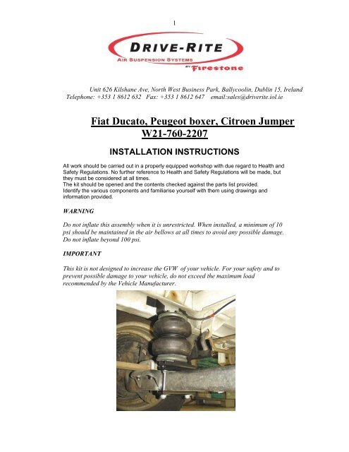
31. PREPARATION:This suspension kit consists of all parts necessary to make a successful installationonto your Vehicle. All parts have been tested thoroughly. Please make sure you takeall necessary safety precautions while fitting the kit.Note: you should first read these instructions carefully and then take all parts out ofthe box and pre-assemble them as far as possible before fitting them onto yourvehicle.2. INSTALLATIONPre-assemble the air bellows as shown in thediagram on the left.Turn Air Fitting away from the two threaded studs.Place the two 10 x 150 bolts into the drilled holes onthe lower bracket.Now bolt the base of the Air Bellow to the LowerBracket using the 3/8-16 UNC hex head boltsPlace one of the bracket straps under the lowerbracket.Position the lower bracket in such a way that itstands parallel to the axle.Fasten the upper bracket to the framework usingM10 x 30 bolts. Ensure the two flanges of the UpperBracket are pushing away from the inside of thechassis as shown.
4Now take the pre-mounted Air Bellow/Bracketassembly, squeeze the Bags together (for ease ofinstallation) and place each assembly in the centre ofthe axle.Bolt the Bellows to the Upper Bracket.The lower bracket now rests loosely on the axle. Theactual attachment of the Lower Bracket is made withone additional Bracket Strap under the axle. Use theM10 lock nuts to fasten to axle.The position of the lower bracket must take place insuch a way that it stands parallel to the axle. Placethermal sleeves over the air lines for protection.See Diagram.LSV - Model type 230After the assembly of the air bellows the LSV mustbe pre-loaded to increase the automatic LoadSensing. The original bracket must be exchanged bya longer bracket, which is included in the kit.The position of this bracket must be made in such away that the distance between the upper and thelower points as shown amounts to 155 mm.See Photograph.LSV - Model type 244After the assembly of the Air Bellows the LSV mustbe pre-loaded to increase the automatic LoadSensing. The LSV clamp must be shifted 25mmtoward the end of the rod as shown. In order toachieve this, the clamping screws (Fig 1) must beloosened and moved 25 mm towards rod end.
5TORQUE SETTINGS:(valid for the most usual mobile travel vehicles)Wheel bolts:Motor vehicle type: Wheel bolt Torque Settings<strong>Fiat</strong> <strong>Ducato</strong> 10/14 M14 x 1,5 160 Nm*²<strong>Fiat</strong> <strong>Ducato</strong> Maxi M16 x 1,5 180 Nm*²Mercedes Sprinter M14 x 1,5 180 Nm*²Heart pin (centering bolt) 8,8 * ³M 8M 10M 1225 Nm47 Nm86 NmU – bolts:M 8M10M12M1425 Nm*³47 Nm*³118 Nm*³130 Nm*²Shock absorber:<strong>Fiat</strong> <strong>Ducato</strong>160 Nm*²MB Sprinter 208-316 above 80 Nm below 70 Nm Screws8.8110 Nm Screws10.9MB Sprinter 408-416 above 140 Nm below 140 Nm* ² manufacturer data* ³ DIN 13, sheet 33 shank end screws quality 8,8, coefficient of friction m = 0,14
6TO AVOID LEAKAGES:The Suspension is inflated with compressed air via nylon hoses with an outsidediameter of ¼ “. The connections are called “Plug-in” connections. This kind ofconnection allows you to attach the air hose without a tool. Here the hose must be putso far into the connection, until it locks. The correct fit can be examined by easilypulling on the hose. To recognize if it is the correct fit, during pulling the hose, thering of the connection moves along with the hose. For the loosening of the hoseconnector the hose must be pushed toward the Plug in connection. Subsequently, withthe ring held, the hose can be taken off.Note: With the pulling to check if the ring is too far pulled out, a leakage can occur!Note: In order to avoid slow air losses, the nylon hose should be cut straight with asharp blade. Do not use a side cutter.Correctly cut. Straight cut off.Wrong.With frequent assembly use a nylontubingcutter.Air fittings:All air fittings are supplied with aneasy “push to connect” fitting. Toprevent leaking of air though, makesure that all tubing is cut squarely.These fittings make it easy to fit theair tubing and also to replace it ifnecessary.
7Brittle:Like all flexible rubber construction units, a certain natural embitterment occurs withthe air bag. This procedure is natural, since the softeners in the plastic evaporate. Ifthis occurs, then this leads to a cracking at the surface layer of the bag. If the auxiliarypneumatic spring is driven with a wrong operating pressure the embitterment isincreased.Air loss/leakage:If within 24 hours the air pressure drops more than 0.2 bar a leak may be on the kit. Ifthis is the case, then the complete kit must be sprayed with soap solution (leakdetection spray). The leak is detected on the basis that bubbles appear. Mostfrequently the bubbles will be seen at the junction points after initial assembly. Mostlythe reason for this is because of the non right-angled cut of hoses. As previouslystated cutting off should take place by means of a straight cutter and not with the sidecutter!Note:When driving on a ferry or when driving through a large bump on the road thepossibility exists that at short notice the kit will be hit with a higher filling pressure(maximum 8 bar) than the vehicle is permitted to drive. Therefore, depending uponmotor vehicle type and loading, the rear of the vehicle rises. This measure must becancelled again however during normal travel, since this affects the braking action ofyour vehicle. If one drives on a high air pressure, then the brake delay of your vehiclecan be reduced. Always guarantee that while driving the maximum operating pressureis kept in accordance with partial appraisals or registration papers.