AME.IM.3000 LCX Install Guide - Earthsafe Systems, Inc.
AME.IM.3000 LCX Install Guide - Earthsafe Systems, Inc.
AME.IM.3000 LCX Install Guide - Earthsafe Systems, Inc.

Create successful ePaper yourself
Turn your PDF publications into a flip-book with our unique Google optimized e-Paper software.
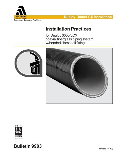
FIBERGLASS - COMPOSITE PIPE GROUPDualoy ® 3000/<strong>LCX</strong> <strong>Install</strong>ation<strong>Install</strong>ation Practicesfor Dualoy 3000/<strong>LCX</strong>coaxial fiberglass piping systemw/bonded clamshell fittingsISO-9001CERTIFICATED FIRMBulletin 9903FP824B (01/02)
Table of Contents1 Introduction .............................................................32 Listings and approvals ...........................................33 Inspection, handling & storage..............................34 Materials...................................................................4Pipe ...........................................................................4Fittings.......................................................................4Adhesive....................................................................4Tools..........................................................................45 Field cutting & tapering primary pipe....................5Cutting .......................................................................5Removing containment .............................................5Tapering with Ameron Taper Maker..........................5Tapering with power tapering tools ...........................66 Piping system layout ..............................................6Trenching, bedding & backfilling ...............................6Supporting valves, accessories & vent lines .............7Precise alignment and make-up................................8Flexible sump penetration fitting installation..............8Jump-overs and Cross-overs ....................................9Reducers ...................................................................97 Bonding primary systems ....................................10Joint preparation......................................................10Mixing Ameron adhesive .........................................10Applying Ameron adhesive......................................10Making the joint .......................................................10Pot life & cure time for Ameron adhesive ................11Force curing Ameron adhesive ...............................11Using heat blankets.................................................11Connecting to non-Ameron fiberglass piping ..........118 Bonding containment piping................................12Joint preparation......................................................12Sealing containment piping .....................................12Terminating the secondary containment .................12Terminating inside the sump ...................................129 NPT threaded connections...................................13Thread preparation..................................................13Making the joint .......................................................13Isolating flex connections at the shear valve...........1410 Repair procedures.................................................14Minor damage .........................................................14Major damage ........................................................1411 Primary system testing.........................................15Recommended practices.........................................1512 Containment system testing ................................15Pneumatic testing....................................................15Provisions for testing and monitoring ......................1513 Simultaneous testing ............................................1614 Health & safety information..................................16Toxicity of adhesive.................................................16Handling precautions for adhesive ..........................16First aid for adhesive users ....................................16Important Notice ......................................................162
1 IntroductionDualoy 3000/<strong>LCX</strong> pipe and fittings are manufactured from thermosetting epoxy resinsreinforced with high tensile strength fiberglass filaments. The pipe is produced by filamentwinding. The pipe incorporates a resin-rich inner liner that is resilient and holiday-free anda resin-rich outer coating that protects the structural wall from UV degradation duringstorage and installation. The structural wall strength of Dualoy 3000/<strong>LCX</strong> pipe isunsurpassed in the fiberglass pipe industry. Fittings are manufactured by filamentwindingor compression molding.Dualoy 3000/<strong>LCX</strong> pipe and fittings are electrically nonconductive and never requirecathodic protection or sacrificial anodes. <strong>Install</strong>ed systems are immune to externalcorrosion from stray-current electrolysis and cathodic interference. They are unaffectedby alkaline or acidic soil conditions.The containment on the pipe is coaxial and an integral part of the piping. The containmentover the fittings is made by applying matched clamshell fittings over the primary fitting,connecting the pipe containment jackets.The primary piping and containment fittings are joined using the same, strong, reliable,bonded joint as in Dualoy 3000/L single wall piping.Dualoy 3000/L single-wall piping systemsDetailed installation instructions for Dualoy 3000/L single-wall piping may be found inAmeron Bulletin 7501 (FP104) available from Ameron Fiberglass Pipe Group or yourAmeron distributor.23Listings andapprovalsU L CU L®mnUnderwritersLaboratories <strong>Inc</strong>.¤Inspection, handlingand storageDualoy 3000/<strong>LCX</strong> is Listed in the United States with Underwriters Laboratories fornonmetallic underground piping for petroleum products, alcohols and alcohol-gasolinemixtures (File MH9162). Dualoy 3000/<strong>LCX</strong> pipe & fittings are also listed with UnderwritersLaboratories of Canada for Petroleum Products and Oxygenated Fuels (File CMH715).InspectionCareful inspection of the outer (secondary) layer of pipe is especially important on coaxialcontainment installations. Since damage to the primary is not visible once the pipe isinstalled, it is essential to check the outer pipe jacket for damage. Testing and experiencehas proven that no damage will occur to the primary pipe without an indication of damageon the outer jacket.Upon receipt at the job site, inspect the pipe fully. Locate, cut out, repair or replacedamaged pipe. Impact damage is usually recognizable as rounded pale areas just underthe surface or as deep gouges, scratches or cracks. Remove end protectors to inspecttapers for damage and then replace protectors.HandlingDualoy 3000/<strong>LCX</strong> has higher impact resistance than single-wall pipe, however, fiberglasspipe is susceptible to damage if handled improperly. Adhere to the following recommendationswhen handling:• Do not transport pipe without proper protection against impact.• Truck pipe racks should be padded with carpeting or like material to prevent damage.• Tie the pipe down during transport to prevent it from bouncing on the racks.• Do not use chains to tie down the pipe on a truck: Use nylon straps or hemp rope.• Do not drop the pipe from truck bed when stringing: Lay the pipe down by hand.• Pipe loads that are properly separated and supported can be unloaded by paddedforklifts.StorageDualoy 3000/<strong>LCX</strong> pipe incorporates a 5-mil thick, resin-rich outer coating which providesoutstanding UV resistance. Pipe stored out-of-doors for extended periods may assume achalky appearance. However, this change in appearance is superficial and does notaffect the pipe’s performance. Protect stored pipe from impact damage by stacking onpadded racks.3
4Materials PipeManufacturer tallies pipe on the basis of overall length. Allow for cutting losses andwastage when ordering.FittingsContained fitting assemblies are sold in the following boxed quantities.Clamshell Fittings per Shipping BoxNominalPipe Size 90° 45° Sleeve Termination(in) (mm) Elbows Elbows Tees Couplings Sleeves2 50 5 5 5 10 103 80 5 5 5 10 104 100 5 5 5 10 10Note: Fasteners are included with fittings. .AdhesiveAmeron supplies PSX •20, PSX •34 and B-20 adhesives. The PSX •20 and PSX •34adhesives are polysiloxane-modified epoxy formulations. All are designed to makepermanent bonds in primary or containment systems containing petroleum products,alcohols, alcohol-gasoline mixtures or oxygenated fuels. They are also approved for usewith MTBE fluids. Each is supplied as a two-part system consisting of a resin and ahardener.Each adhesive kit contains:• Resin• Hardener• Mixing stick• Spatula and/or brush• Detailed usage instructions• Emery paper• Gloves• Paper towelsRefer to the layout drawings to estimate the number of adhesive kits required. <strong>Inc</strong>ludebonds for all fittings, elbows, tees, reducers, adapters and couplings plus a waste factor.Short pot life at higher temperatures may not allow as many bonds to be made asindicated in the table: allow a greater waste factor at higher temperatures. For furtherinformation refer to the adhesive product data sheet.Primary Bonds per Kit 1NominalPipe SizeAdhesive Kit Size(in) (mm) 3 oz. 2 5 oz. 2 8 oz. 2,32 50 6 12 –3 80 3 8 144 100 2 6 91 The average number of primary system bondsobtainable by an experienced crew at 75°F.2 Available in six-pak kits.3 Excessive waste may result when using the 8-ozkit to make 2-inch bonds.Containment Bonds per Kit 1NominalPipe SizeAdhesive Kit Size(in) (mm) 3 oz. 2 5 oz. 2 8 oz. 22 50 1 3 3 43 80 1 3 1 24 100 1/21/2 11 The average number of primary system bondsobtainable by an experienced crew at 75°F.2 Available in six-pak kits.3 Fewer bonds on tees would be typical, morefor termination sleeves.When using pneumatic tools,the air supply must be dry andoil-free as moisture or oil onbonding surfaces will interferewith the adhesive.ToolsThe following tools are recommended to install Dualoy 3000/<strong>LCX</strong> piping:• 3 ⁄8-inch electric drill or equivalent air-driven motor• Fine blade hacksaw, radial cut off saw or circular saw• 5- or 6-inch hole saw for installing sump penetration fittings• Large pliers capable of gripping a 4-inch object• Containment jacket stripping tool• 1 1 ⁄2 -inch disc grinder wheel for abrading sump wall at penetration• Heat blankets, heavy-duty heat guns, or hot air blowers for cool/cold-weather installation.• Tapering tool as described on the next page.4
5Field cutting andtapering primary pipe(cont'd.)Tapering with power tapering toolsPipe is most often tapered using one of several power tapering tools. Manufacturers’names and addresses may be obtained from Ameron distributors. Pipe tapered withthese tools should be periodically checked against a factory taper for taper length andtaper angle.On 2" pipe, it may be possible to simultaneously remove the containment jacket and taperthe primary pipe in one step with some power tapering tools. Consult Ameronengineering department for information.Fig. 5-3. Dualoy 3000/<strong>LCX</strong> can betapered using the Ameron TaperMaker. The ratchet handle makes theTaper Maker convenient to use inconfined spaces when repairingexisting lines.Fig. 5-4. Pipe is typically tapered usingone of several power tapering toolsavailable from outside sources.Observe the following procedures whenoperating the Taper Maker.• Check blade angle by using a factory taperas a guide. When properly adjusted, theblade should be in contact with the taperover the entire taper length. If adjustmentis required, loosen the blade retainingscrews and adjust the blade angle with theset screw.Taper lengthsNominal Taper ContainmentPipe Size Length Removed(in) (mm) (in) (mm) min. (in., mm)2 50 1 1 ⁄2 38 2 3 ⁄4 703 80 1 3 ⁄4 44 2 3 ⁄4 704 100 1 7 ⁄8 48 3 1 ⁄2 89• Mark the required taper length on the pipe. Refer to the taper length table below.• Insert the threaded collet shaft through the base casting and the mandrel.• Select the appropriate size collet and slide it onto the mandrel, making sure the keyinside the collet engages the slot of the mandrel.• Hold the collet and turn the collet control knob clockwise until the collet begins toexpand. Note that it may be necessary to adjust the cutting head to accommodatedifferent size collets.• Insert the collet into the pipe until the back end is flush with the end of the pipe.• Expand the collet to grip the inside of the pipe by turning the collet control knobclockwise.• Lower the cutting blade until it contacts the pipe by turning the cutting headadjustment handle clockwise.• Using the ratchet handle, turn the tool clockwise, gradually lowering the cuttingblade by turning the cutting head adjustment handle clockwise. Continue until asmooth taper of the proper length is obtained. The thin edge of the completed tapershould be no less than 1 ⁄32 inch (0.75 mm) thick.For complete operating information, refer to the appropriate Taper Maker ProductData/Operating Instructions.6Piping system layoutTrenching, bedding and backfillingThe smaller outside diameter of the Dualoy 3000/<strong>LCX</strong> coaxial pipe will save on trenchingand backfilling costs. The ability to fabricate close “Jump-Over” fittings also helps reducethe depth of excavation needed to maintain trench slope. Although fiberglass pipe hasexcellent strength, it must be protected against impact which may occur from improperhandling or during backfilling.• Provide a trench width equal to the pipe diameter plus six inches on each side.Separate multiple lines by at least 4 inches. Refer to Fig. 6-2.• Provide a minimum of 18 inches of select backfill between the top of the pipe andunpaved ground surfaces.• Provide a minimum of 4 inches of select backfill between the top of the pipe andreinforced concrete pavement (4 inches minimum thickness).• Provide a minimum of 8 inches of select backfill between the top of the pipe andasphalt pavement (2 inches minimum thickness).• Slope the trench bottom evenly from the dispensers back to sumps or tanks at aminimum slope of 1 ⁄8 in/ft.• The trench bottom must be free of hard or sharp objects.6
6Piping system layout(cont'd.)• Grade the trench bottom with at least 6 inches of select backfill to provide firm, evensupport for the pipe. Compact the subgrade well to prevent differential settling.• Protect the pipe from impact during backfilling and abrasion during operation bysurrounding it with four to six inches of select backfill such as washed sand, peagravel ( 3 ⁄4-inch maximum) or crushed stone ( 1 ⁄2-inch maximum).• Wrap pipe lying near concrete with rubber or foam padding to avoid direct contactwith the concrete.None4 (min)ConcreteAsphalt2 (min)18 (min)Fig. 6-1. During layout, bonding andinspection, support the piping on2x4 “batter boards” to keep thejoints clean and to keep beddingout of the pipe.4 (min)8 (min)Fig. 6-2. Use only select materials forbedding and backfilling Dualoy3000/<strong>LCX</strong> fuel handling systems. Nativematerials are rarely suitable and shouldnot be used.NativesoilSelect backfill4 (min)6 (min)6 (min)Supporting valves, accessories and vent linesDo not use fiberglass pipe to support the weight of heavy items in a line such as valves,strainers and steel vent riser pipes. Provide separate supports for valves andaccessories.PermanentstructureFig. 6-3. Support risers by attachingthem directly to structure walls.Steel pipe clampSteel nippleSteel riserSteelcouplingSteel elbowBell x maleadapterDualoy 3000/L fiberglass pipe7
6Piping system layout(cont'd.)Bell x male NPT adapterSlope to tank1⁄8 in/ft (min)Dog leg (4 ft min)Single wall fiberglassvapor recovery lineFig. 6-4. Use flexible connectors toconnect fiberglass pipe to tanks,turbine outlets at tanks and to shearvalves at dispensers. A 4-ft. minimumlength of fiberglass pipe (dogleg) isallowable per API Specification 1615 inlieu of a flexible connector.Dog leg (4 ft min)Contained fiberglassproduct lineDogleg (4 ft min)Galvanized elbowTurbine pumpBell x male NPT adapterBell x male NPT adapterGalvanized elbowNote: sumps not shown for clarityPrecise alignment and make-upThe matched taper bell and spigot joint on the primary does not always result in a preciseand predictable insertion depth. This variation results from:• Manufacturing tolerances in the bell• Differences in length of tapers prepared on the job site• Difference of insertion depth when dry fit and after adhesive has been applied.Flexible sump penetration fitting installation• Measure to the appropriate height for the center of the hole, making sure to allowfor the desired slope for the piping in the station layout.• Mark the height across sump.• Measure and mark the location of each penetration on the line, on the flat panel.• Using a 5-inch hole saw for dispensers, 6-inch for tanks, cut a hole for thepenetration fitting.• Sand and clean the edges to create a smooth surface to properly seat the fittingin the sump wall. (continued on page 9 at top)Fig. 6-5.a) Typical sump penetration detail for asystem piped in parallel or at last sumpof a system piped in series.b) Typical sump penetration detail for asystem piped in series and utilizingtermination tees. Allows pressurerating on secondary of 30 psi.c) Typical sump penetration detail for asystem piped in series. Note: Low testpressure needed if connecting tube ispressurized.Note: 24-inch minimum widthrecommended on dispenser sumps tofacilitate series installations.8Bondedclamshellterminationassemblywithtest portDualoy 3000/L90° elbowwith 1-1/2”threadedbushingDualoy3000/<strong>LCX</strong>bondedclamshelltermination teeShallow sumppenetration fittinga b cContainmentConnectingTubeBondedclamshellterminationtest reducer
6Piping system layout(cont'd.)Fig. 6-6. Jump-over assembly made withnext larger size single-wall pipe andclamshell fittings cut at start of taper toallow minimum length.BBAFig. 6-7. Cross-over assembly made with<strong>LCX</strong> pipe and full clamshell fittings forinstallations where longer length isallowed or needed.AFlexible sump penetration fitting installation (cont’d)• The flexible penetration fitting has two sections, an outer ring and an inner boot.Unscrew the ring from the penetration fitting and apply a small bead of Bostik 920 tothe inner surface of the ring flange.• Apply a bead of Bostik 920 around the hole on the inside surface of the sump wall.• Place the ring into the sump wall from the outside with the threads inside the sump.• Press the gasket into the groove on the inner part of the penetration fitting.• From inside the sump, screw the penetration fitting onto the threads and tightenwith adjustable pliers.Jump-overs and Cross-oversAssemblies for crossing lines can be made in one of two ways. For lines where the teeand 45° elbow need to be very close (a Jump-over), the clamshell fittings can be cut at thebeginning of the tapered portion on the branch of the tee and one leg of the elbow. A pieceof single wall pipe of the next larger size can be used to connect the clamshell fittings (Fig.6.6). For lines where there is sufficient distance between the tee and 45° elbow to allowfor the full clamshell fittings, the cross-over can be made by simply bonding the fittingsand clamshells to a piece of standard coaxial pipe. (Fig. 6.7)Nominal Minimum Length (A) Minimum Height (B)pipediameter Jump-Over Cross-Over Jump-Over Cross-Over(in.) (mm) (in.) (mm) (in.) (mm) (in.) (mm) (in.) (mm)2 50 7 1 /2 190 12 5 /8 320 5 1 /4 135 9 2273 80 9 3 /4 250 14 3 /4 375 6 7 /8 175 10 1 /2 2654 100 10 1 /4 260 16 1 /2 420 7 1 /4 185 11 5 /8 295ReducersThe Dualoy ® 3000/<strong>LCX</strong> Coaxial Piping System can be reduced from 3” to 2”, 4” to 3” and4” to 2”. See Figure 6-8.Mark the “X” Dimension on the outside of smaller secondary prior to bonding primary:• Sand bonding surface of jacket.• Apply adhesive and place clamshell reducerring in place. Allow adhesive to cure.• After all primary bonding, curing and testing iscomplete, bond clamshell containment fittingin place on larger secondary pipe andclamshell reducer ring.Reduction(X)3” to 2” 3 3 /44” to 3” 4 1 /44” to 2” 4 1 /4Dualoy 3000/Lprimary fittingXDualoy3000/<strong>LCX</strong>smallerdiameter pipeFig. 6-8. ReducerDualoy3000/<strong>LCX</strong>clamshellsecondaryfittingClamshellreducerringDualoy3000/<strong>LCX</strong>larger diameterpipe9
7Bonding primarysystemsThe hardener contained in theadhesive kit may burn the skin.Avoid inhaling the vapors. Readand observe the labelprecautions.Joint preparationAll tapered systems must be clean, dry and warm for a proper bond.Clean: Pipe is shipped from the factory with end protectors. Avoid contamination fromfingerprints, petroleum fumes, mist and condensation as these are adverse to goodbonding. If a taper becomes dirty, sand it with emery cloth. Never touch the bondingsurface with bare hands after cleaning or sanding as this will leave an oily deposit.Dry: Adhesive will not bond to a wet surface. If the taper is wet or moist, dry it with a blowdryer or heat gun. Do not overheat or burn the pipe.Warm: Below 50°F (10°C), warm the taper with a blow dryer or heat gun. For bestresults, adhesive should be at least 50°F when used. Do not store kits in areas above100°F (38°C), below 32°F (0°C), or in the direct sunlight during warm weather. In coldweather, warm the resin to at least 50°F but not above 100°F to permit good mixing andeasier application.Mixing Ameron adhesive• Combine all of both components in the mixing container in the suppliedproportions.• Never try to split a kit.• Mix thoroughly with the mixing stick until all streaks are gone and the adhesive hasa smooth, uniform color. Mixed adhesive color is dark red.• Do not allow moisture to get into the can.Note: If the material in either container cannot be mixed, the kit should not be used.Grit in adhesive may be sitting on top of resin component. It will mix in readily.Fig. 7-1. Tapered pipe ready for dry fit.Fig. 7-2. Completely wet all matchingsurfaces with the adhesive. Wipe offexcess adhesive with the spatulaprovided in the kit.Applying Ameron adhesivePSX•20 and PSX•34 adhesives contain grit to aid in installation. Excessiveamounts of adhesive may (1) cause flow restriction inside the pipe when theadhesive has cured, (2) block the opening of the containment pipe, or (3) result in‘hydraulic backout’ as the adhesive cures. Hydraulic backout occurs when excessadhesive prevents the joint from maintaining an interference fit and the spigot backs outof the bell during cure. The inclusion of grit reduces this possibility significantly.Coat the tapered surface and coat end of the primary pipe or the entire tapered section ofadapters with adhesive. Apply a thin, even coat of mixed adhesive to the inside of the bellof fittings . Completely wet all matching surfaces with the adhesive. Wipe off excessadhesive with the spatula or brush provided in the kit.At fittings where the containment is to be terminated, take care when applying adhesive soexcess adhesive does not get on primary pipe where termination sleeves will need to seal.Making the jointAfter aligning the mating surfaces so that they may be brought together in a straight line:• Insert spigot all the way into the bell.• Twist one quarter of a turn, when possible, while pushing together to distributeadhesive evenly and to achieve an interference fit. A slight reverse twist will thenlock the joint.• Remove any excess adhesive.• Do not cock the joint.• Over-insertion of the joint may collapse the spigot and cause a leaky joint.• Under-insertion of the joint may also cause a leaky joint.• Do not drive the joint together with a hammer.• Do not disturb the joint while the adhesive is uncured.• Do not move adjacent pipe and fittings until adhesive has set.10
7Bonding primarysystems (cont'd.)Temperatures in a trench or outof direct sunlight may be lowerthan measured ambient surfacetemperatures.BlanketFittingThermostatFig. 7-3. Place the thermostat end of theblanket against the joint with thermostatfacing out. Wrap the rest of the blanketaround the joint so that the overlapcovers the thermostat.Pot life/cure times for Ameron adhesivePot life is measured from the time the hardener and resin are first mixed until the adhesivestarts to thicken and harden and no longer can be used. Do not use adhesive once thecan has become hot.The table below indicates the adhesive pot life under various temperature conditions. Inhot weather, pot life may be extended by wrapping a damp rag around the can of mixedadhesive or by spreading the adhesive on aluminum foil to dissipate the heat.Pot life/cure times for Ameron adhesiveMinimum Ambient Adhesive Minimum JointTemperature Pot Life Cure Time*(°F) (°C) (minutes) (hours)40 5 70 1265 18 40 575 24 30 495 35 20 3* Cumulative totals. Cure time at listed temperatures need not be uninterrupted, buttotal time must equal the tabulated time before the system is pressure tested.Force curing adhesiveAt temperatures below 50°F (10°C) or if the temperature will not be above 50°F (10°C)during the entire period of cure, an external heat source must be used to force cure theadhesive. The adhesive and the bonding surfaces should be warmed to 50°F (10°C)before mixing and applying the adhesive.Below 50°F (10°C) force cure the adhesive with an external heat source such as:• Ameron <strong>LCX</strong> heating blanket• Forced air heater if the trench is covered to contain the heat• Hot air gunUsing Ameron heating blanketsThe heating blanket reaches a maximum temperature of 300°F (150°C), which will cureAmeron adhesive in approximately 30 to 40 minutes. Detailed instructions are includedwith the blanket. Observe the following points:• Use one heating blanket per bond.• Tie the blanket in place with nonconducting ties.• Before connecting to a power source, inspect the blanket and cord for loose wireconnections and bare wires.• Do not plug the cord into a power source when standing in water or on a wet surface.• Check that the heating blanket has the correct AC voltage rating for your locality.Do not use direct current.• Mark the starting and disconnect time on the pipe with a grease pencil so that youwill have a record of cure for each joint.• Verify that the blanket actually heats up after being plugged in.• Do not move or disturb the joint during cure.Fiberglass insulation backed byaluminum foil4Fig. 7-4. When it is below 50°F (10°C),close the pipe ends and insulate aroundthe blanket. Overlap the blanket about 4inches on each side and tie down theends of the insulation.Connecting to non-Ameron fiberglass primary pipingConnect Dualoy 3000/<strong>LCX</strong> fiberglass piping and non-Ameron UL Listed fiberglassprimary piping by means of threaded adapters. Do not adhesive bond Ameron piping tothat of another manufacturer. Bond the appropriate adapter from each manufacturer tothe manufacturer’s pipe using that manufacturer’s adhesive. Complete the threadedconnection using thread sealant, not pipe adhesive. By following this procedure you canuse Dualoy 3000/<strong>LCX</strong> piping to extend an existing line that employs the pipe from11another manufacturer without affecting the UL Listing of either system.
8 Bondingcontainment pipingApplyingadhesive tothe flangesand the curvedsurface of thefitting wherethe pipe will fit.Adhesiveapplied to theoutside of thecontainmentpipe.Completedconnectionwith bolts inplace.Joint preparationInspect all sealing surfaces to insure they are free of any foreign material such as dirt,sand, or adhesive. (Compressed air works very well for removing foreign material.)Inspect all sealing surfaces to insure there are no cuts, scratches, or nicks which couldprevent the joint from sealing properly.Adhesive for containment pipingThe same PSX•20 adhesive used for primary bonding is used for bonding containmentfittings.Sealing containment piping• Bond containment only after primary lines have been tested, inspected and approved.• All bonding surfaces must be free from water, soap, oil, grease, dirt and other contaminatesand should be sanded before applying adhesive.• Apply a uniform coating of adhesive to the flanges of each of the containment fittinghalves, to the outside of the containment pipe and to the curved surface of the fittingwhere the pipe will fit. Keep adhesive off the last 1/2 inch of the pipe jacket whenapplying it to the pipe.• Place the containment half-shells around the primary fitting. Since the primaryassembly of the Dualoy 3000/<strong>LCX</strong> is rigid relative to the containment piping, thecontainment fittings will not have to be held so tightly that they must resist containmentpipe movement. Once in place, assemble fasteners supplied with the fittings to hold thehalves in place until the adhesive cures. See Figure 8-2.Fig. 8-1. Assemblysequence to seal thecontainment of theDualoy 3000/<strong>LCX</strong> fitting.Fig. 8-2Terminating the secondary containment•Clamshell termination assemblyApply adhesive to all bonding surfaces after sanding, as described above. Position theclamshell termination assembly over the cut jacket so that the jacket end is centered inthe clamshell. Particular care must be given to assure excess adhesive is not used as itmay cause sealing of the containment. See Figure 8-3.test valveFig. 8-3. Dualoy 3000/<strong>LCX</strong> moldedtermination assembly to seal offsecondary containment.2” available with or without test valve. 3and 4” are available only with test valve.<strong>LCX</strong> pipe12Clamshell termination sleeve
8 Bondingcontainment piping(cont’d)Clamshell TerminationAdapter(front & side)9 NPT threadedconnectionsClamshellTerminationAdapterOn bell x female adapters, usepipe wrench over threaded portiononly. On bell x male adapters, usepipe wrench on steel nipplewhenever possible.Terminating inside the sumpFor series lay-out patterns, the means of terminating the containment of the branch leg ofthe in-sump tee or elbow is with a bonded termination adapter. The adapter is bonded tothe exterior of the fitting leg to be terminated, prior to the clamshell containment fittingbeing placed on the assembly.• Lightly sand the outside surface of the leg of the primary fitting on which the terminationis to be done.• Abrade the inner surface of the termination adapter also, to provide a fresh surface towhich to bond.• Cut the tapered end portion of the containment fitting leg which is to be terminated.Abrade the inner surface of the shortened leg of the containment fitting to prepare it forlater bonding.• Apply a moderate coating of adhesive to outer surface of the primary fitting and theinner surface of the termination adapter. Keep the outer surface of the adapter dryand free of adhesive.• Fit the adapter onto the primary fitting.• Dry fit tapered Dualoy 3000/<strong>LCX</strong> pipe legs into the bell ends of the primary fittingswhich are not to be terminated.• Place the clamshell containment fitting over the primary fitting-adapter assemblyand hold in place with bolts while the adhesive cures. This will assure properalignment of the adapter for final assembly. Care should be taken to assureadhesive does not touch the clamshell fitting at this point as it is to be removedwhen the adhesive between the primary fitting and the adapter is cured.• Once the adhesive has cured, remove the bolts and the clamshell fitting. <strong>Install</strong> theassembled primary fitting into the primary system.• Use the prepared clamshell fitting to close the containment system when primarytesting and inspection is done.Thread preparation• Inspect threads on fiberglass adapters and threaded bushings.Do not use if threads are damaged.• Inspect threads on steel fittings for burrs.• Remove burrs from steel fittings by making up to mating steel threads. Unmakethe steel fitting and reinspect.• Always dry fit fiberglass and steel threads without sealing compound. It should bepossible to dry fit the threads as shown in the following table. If the proper numberof threads cannot be made up, select a new steel fitting.In general, threaded connectionsshould be made up beforeadhesive-bonded joints tominimize the possibility of damageto bonded joints caused bytorquing the threadedconnections. However, wheninstalling molded threadedbushings (tapered major nominalpipe size x threaded minornominal pipe size) make thetapered bonded joint first andallow it to cure before making upthe threaded joint. This order ofjoint make-up will prevent damageto the bushing.Making the jointThreads must be clean and dry before applying thread-sealing compound.• Use a nonhardening, solvent-free Teflon based thread sealant such as JomarSeal “The Heavyweight” or Gasoila Soft Set pipe sealant.• Apply sealing compound to male and female threads.• Hand tighten the joint, thenuse a wrench to get fullmake-up. Standard pipewrenches can be used withcare on fiberglass adapters.Do not overtighten.• The parts should make up thenumber of threads shown inthe table above. Otherwise, aproper seal may not beeffected when tightened.Threads to Dry Fit and to SealNominalPipe SizeThreads to Additional(in) (mm) Dry Fit Threads to Seal1 1 ⁄2 40 4-5 32 50 4-5 33 80 5-6 34 100 6-7 213
9NPT threadedconnections (cont’d)Never use a pipe wrench directlyon the pipe: wrench up only onadapters.Isolating flex connectors at the shear valveWhen flex connectors are directly buried at the dispenser, regulations frequently requirethat they be cathodically protected and provisions be made to avoid stray currentelectrolysis and corrosion. In such cases the flex connector must be electrically isolatedfrom the shear valve and from other metallic components in the system. Experience hasshown that nylon isolation adapters do not perform well inasmuch as the poormechanical strength of the material results in creep or thread deformation withsubsequent leakage.Ameron manufactures a 1 1 ⁄2 NPT female x 1 1 ⁄2 NPT male fiberglass-reinforced isolationadapter which may be mounted between the flex connector and the shear valve. Followthe same general installation procedures as with other NPT threaded fittings. Afterapplying the sealing compound, hand tighten the adapter. Final make-up requires 1 1 ⁄2 to2 additional turns.2 7 ⁄81 1 ⁄2 NPTmaleShear valve1 1 ⁄2 NPT femaleDualoy isolationadapter1 3 ⁄8Fig. 9-1. The Ameron fiberglassreinforcedisolation adapter is mountedbetween the flex connector and theshear valve.2 1 ⁄41 1 ⁄2 NPTfemaleSS flex connector1 1 ⁄2 NPT maleboth ends(by others)1014Repair proceduresDualoy 3000/<strong>LCX</strong> is very resistant to impact damage. It can be damaged, however,by paving stakes, large concrete pieces or other hazards. In the event of damage, thepipe can be repaired using these procedures.Usually the damaged area is obvious. If the exact location of the damage cannot bedetermined, it may be necessary to replace that full length of pipe. Standard leakdetection methods (soapy water) can be applied progressively along the length of pipeto locate the damaged or defective section. If the primary pipe is leaking at an unknownlocation, the cut ends of the jacket at each end of each piece of pipe can be soaped toisolate the leak. If the containment pipe is leaking, the surface can be soaped.Minor damage (isolated to less than one inch of pipe length)• Cut out the damaged pipe.• Remove the jacket and taper each of the ends of the remaining pipe• Assemble primary coupling following standard installation practices.• Assemble containment coupling following standard installation practices.Minor damage [containment only] (isolated to less than one inch of pipe length)• Sand area around damaged area - approximately one inch in all directions.• Recover cut jacket section from jacket cutter, remove tape and sand frominner surface. Sand inner surface.• Apply thin coating of adhesive to sanded surfaces.• Wrap jacket section over pipe and secure in place until adhesive cures.Major damage (greater than one inch of pipe length)• Remove at least 15 inches of pipe length or the full length of pipe if damagedarea is greater.• Remove the jacket and taper each of the ends of the remaining pipe• Dry fit two couplings and intermediate pipe nipple into the gap.• Proceed as above for each end of repair area. Finished repair is as shown onthe next page.
10Repair procedures(cont’d)Once the pipe is buried and the site is paved, repair requirements are extremely rarefor Dualoy 3000/<strong>LCX</strong>. If the pipe does become damaged, sections can be isolatedand tested between sumps to locate the problem area. Pavement may need to beremoved to access the damaged pipe.Fig. 10-1. Completed repairsection using Dualoy 3000/<strong>LCX</strong>coupling assembly11Primary systemtestingThese recommendations are offeredonly as a guide. Ameron assumes noresponsibility or liability for the consequencesof any testing practices.Ameron recommends hydrostatictesting of primary systems as theeffects of sudden pressure loss whentesting with liquids are far less severethan with gases. If pneumatic testingis necessary, restrain the systemadequately to prevent damage orinjury in case of rapid pressure loss.Pneumatic testing can be extremelydangerous and is not recommended.Recommended practicesPlan tests carefully and carry them out with all due precautions. Pressurizingequipment should be suited to the size of the system and the pressure required andshould be operated by qualified and experienced personnel only.• Pressure sources should be capable of approaching test pressure gradually.• Use gauges with a full-scale reading of no more than twice the test pressure: Donot use a 100 psi gauge for a 10 psi test. Use reliable gauges calibrated againsta dead weight tester and zeroed for atmospheric pressure.• Isolate tanks from the piping when pressure testing.• The recommended hydrostatic pressure is 150% of expected operatingpressure and should be maintained at least 10 minutes.• Do not exceed 150% of system rating. Check the pressure rating of all thecomponents of the system—not just the pipe—because hoses and flexibleconnectors are almost always rated lower than the pipe.• Do not adjust fittings while system is under pressure. If threaded adapters orbushings leak, release the pressure before attempting to tighten.• Temperature changes can affect the pressure in the test line. Substantialpressure increases may occur in closed systems exposed to the sun.Conversely, overnight decreases in pressure due to cooling from afternoon toearly morning are normal and do not necessarily indicate a leak.• After testing, maintain 5 to 10 psi (35 to 70 kPa) in the system duringsubsequent construction so that damage caused by stakes, excavationequipment, etc,. can be detected and corrected before pavement is installed orproduct is pumped.12 Containmentsystem testingPneumatic testingPlan tests carefully and carry them out with all due precautions. Pressurizing equipmentshould be suited to the size of the system and the pressure required and should beoperated by qualified and experienced personnel only. Pressure sources should becapable of approaching test pressure gradually.Use gauges with a full-scale reading of no more than twice the test pressure. Do not usea 100 psi gauge for a 10 psi test. Use reliable gauges calibrated against a dead weighttester zeroed for atmospheric pressure.The volume of air in the interstitial space is very small, so use of a regulator isrecommended to control the pressure during filling of the line.Pneumatic testing at approximately 30 psi is recommended and is the preferred methodof testing containment piping.Provisions for testing and monitoringThe clamshell termination sleeves with test valves are equipped with a 1 ⁄4 inch Schradervalve which can be used to attach pressurizing equipment. It may be necessary toremove the internal valve prior to attaching pressurization equipment. Use proper tool todo so.Should gauge readings fail to remain stable and the testing is being done pneumatically,use a soap solution to locate leakage.15
13 Simultaneoustesting14Health and safetyinformationFOR CHEMICAL EMERGENCYSPILL, LEAK, FIRE, EXPOSUREOR ACCIDENTCALL CHEMTREC - DAYOR NIGHT1-800-424-9300Toll-free in the continental U.S.483-7616 in District ofColumbiaFor calls originating outside thecontinental U.S.202-483-7616 -Washington D.C.collectALL CALLS ARE RECORDEDSimultaneous testing of the primary and bonded containment section will not normallybe done as the containment system will not be closed until the primary has passedtesting. However, it may be advisable to maintain a pressure on the primary duringtesting of the containment in order to precisely test both systems. If this is done, thepressure in the primary should be at least 10 psi. different than the containment testpressure (higher or lower). If a leak does exist in the primary, it will be very evident dueto a change in pressure in the relatively low volume containment system.Toxicity of adhesiveHardener: Irritating to the skin, eyes and respiratory tract: toxic orally; may cause sensitization.Resin: May be mildly irritating to skin and eyes; may cause sensitization.Handling precautions for adhesiveHardener: Do not get in eyes, on skin or clothing. Avoid breathing vapor. Wash thoroughly after handling. Whenhandling in the field, wear gloves and eye protection. When handling in bulk quantities, wear rubber gloves, rubberapron and NIOSH approved respirator.Resin: Avoid contact with eyes, skin or clothing. When handling in the field, wear gloves and eye protection. Washthoroughly after handling.First aid for adhesive usersIn case of contactEyes: Immediately flush with plenty of water for at least 15 minutes. Call a physician.Skin: Wash with water and soap if available.Clothing: Remove contaminated clothing and wash before reuse.Inhalation: Remove to fresh air. Give oxygen or artificial respiration if necessary.Ingestion: If hardener is swallowed and person is conscious, give plenty of water or milk to drink. Do not inducevomiting. Call a physician. If resin is swallowed, give 100 grams (about 1 ⁄4 lb) of activated charcoal slurry in water.Do not induce vomiting. Call a physician.Important NoticeThis literature and the information and recommendations it contains are based on data reasonably believed to bereliable. However, such factors as variations in environment, application or installation, changes in operatingprocedures, or extrapolation of data may cause different results. Ameron makes no representation or warranty,express or implied, including warranties of merchantability or fitness for purpose, as to the accuracy, adequacy orcompleteness of the recommendations or information contained herein. Ameron assumes no liability whatsoeverin connection with this literature or the information or recommendations it contains. Product specifications aresubject to change.FIBERGLASS - COMPOSITE PIPE GROUP - HEADQUARTERSP.O. Box 801148 • Houston, TX 77280 • Tel: (713) 690-7777 • Fax: (713) 690-2842 • http://www.ameron.comAsiaAmeron (Pte) Ltd.No. 7A, Tuas Avenue 3Singapore 639407Tel: 65 861 6118Fax: 65 862 1302/861 7834EuropeAmeron B.V.J.F. Kennedylaan 74191 MZ GeldermalsenThe NetherlandsTel: +31 345 587 587Fax: +31 345 587 561AmericasP.O. Box 878Burkburnett, TX 76354Tel: (940) 569-1471Fax: (940) 569-2764CompositesP.O. Box 7137011 McBride StreetNewnan, Georgia 30263Tel: (770) 253-2000Fax: (770) 253-9234Centron InternationalP.O. Box 490600 FM 1195 SouthMineral Wells, Texas 76068Tel: (940) 325-1341Fax: (940) 325-9681©1999 Ameron • Printed in U.S.A. • FP824A (5/00) supercedes FP824 (9/99)