032172a qs install.qxp - Lutron Lighting Installation Specialists
032172a qs install.qxp - Lutron Lighting Installation Specialists
032172a qs install.qxp - Lutron Lighting Installation Specialists

Create successful ePaper yourself
Turn your PDF publications into a flip-book with our unique Google optimized e-Paper software.
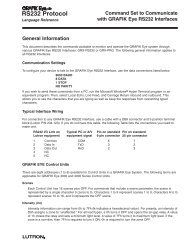
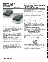
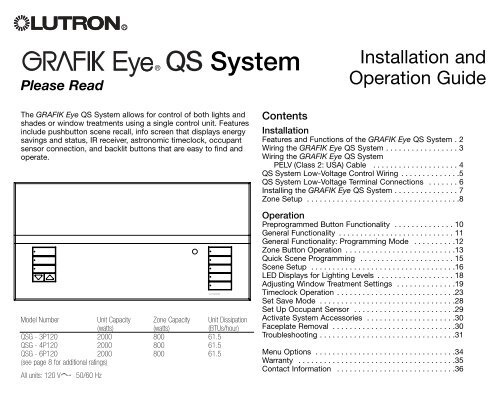
Features and Functions of the GRAFIK Eye® QS SystemHinged faceplateSpace for futureshade columnsZone numbersZone raise/lower buttonsZone LEDs display current{1 2 3 4 5 6 Info screenDisplays status;OKMaster buttonsTemporarily raise and lowerShade columnPreset and raise/lowerbuttons with integral LEDs(maximum of 3 columns)<strong>Lighting</strong> columnScene buttons with integralTimeclock status buttonDisplays currentOK buttonUsed for programmingHinged faceplateInfrared receiverFor handheld remoteuseUSB type mini B inputRGRAFIK Eye® QS System <strong>Installation</strong> and Operation Guide 2
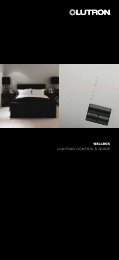
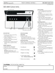
Wiring the GRAFIK Eye® QS SystemImportant Wiring Information• Use properly certified cable for all linevoltage/mains cables.• Proper short-circuit and overloadprotection must be provided at thedistribution panel. You can use up to a20 A maximum circuit breaker/MCB foryour <strong>install</strong>ation.• Install in accordance with all local andnational electrical codes.• PELV (Class 2: USA) terminals may beunplugged for ease of IR, occupantsensor, and control wiring.Caution! Before connecting theloads to the control unit, test theloads for short-circuits.1.Turn power OFF at the circuit breaker orfuse box.2.Connect a standard light switch betweenthe live lead and load wire to test thecircuit.3.Turn power ON and check for short oropen circuits. If load does not operate,the circuit is open. If the breaker/MCBtrips (fuse blows or opens), a load shortmay exist. Correct short or open circuitsand test again.Hot/LiveNeutralSwitchLoadCaution! Do not connect linevoltage/mains cable to PELV(Class 2: USA) terminals.• Earth/ground terminal connection mustbe made as shown in wiring diagrams.• Do not mix different load types on thesame zone.• Follow all local and national electricalcodes when <strong>install</strong>ing PELV (Class 2:USA) wiring with line voltage/mainswiring.• Test for short-circuits on loads beforewiring QS control unit.To connect the line voltage/mainscables to the control unit:1.Strip 5/16 in. (8 mm) of insulation off theline voltage/mains cables in the wallbox.Danger! GRAFIK Eye QS control units must be <strong>install</strong>ed by a qualified electricianin accordance with all applicable regulations and building codes. Improperwiring can result in personal injury or damage to control units or otherequipment. Always turn off circuit breaker or remove main fuse from power linebefore doing any work. To avoid overheating and possible damage toequipment, do not <strong>install</strong> dimming devices to dim receptacles, motor-operatedappliances, or fluorescent lighting not equipped with <strong>Lutron</strong> Hi-lume®, Eco-10TM,or Tu-Wire® electronic dimming ballasts, or devices approved for your location.In dimmed magnetic low-voltage circuits, you can prevent transformeroverheating and failure by avoiding excessively high current flow: Do not operatecontrol units with any lamps removed or burned out; replace any burned outlamps immediately; use only transformers that incorporate thermal protection orfused primary windings. Control units are designed for residential andcommercial use, for indoor use only.3/8 5/16 in. (10 in. mm)(8 mm)2.Connect the line voltage/mains, ground,and load wires to the appropriateterminals on the back of the control unit.The recommended <strong>install</strong>ation torque is5.0 in.-lbs. (0.6 N•m) for linevoltage/mains connections and 5.0 in.-lbs. (0.6 N•m) for the earth/groundconnection.RGRAFIK Eye® QS System <strong>Installation</strong> and Operation Guide 3
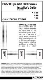
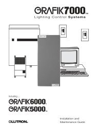
Wiring the GRAFIK Eye® QS SystemPELV (Class 2: USA) CableIR Wiring#18 AWG (1.0 mm 2 )each terminalFrom externalIR connection(by others)1 21: IR DATA2: IR COM1 2 A B COccupant Sensor Wiring#18 AWG (1.0 mm 2 )each terminalA B CA: OCC SIGB: 24 VC: OCC COM1 2 3 41 2 3 4 5 6 L NOccupantsensorControl WiringCommon and power (terminals 1 and 2):Two #18 AWG (1.0 mm 2 ) each terminalLine Voltage/Mains Cablesand Load Wiring#12 AWG (2.5 mm 2 )each terminal1 2 3 4 5 6 L NTo control stations,window treatments, orother GRAFIK Eye QScontrol units1 2 3 41: COM2: 24 V3: MUX4: MUXTo Load 1To Load 2To Load 3To Load 4To Load 5Data (terminals 3 and 4):Twisted, shielded pair #22 AWG (1.0 mm 2 )each terminalNote: Use appropriate wire connecting devices asspecified by local codes.To Load 6120 VL NDistribution PanelRGRAFIK Eye® QS System <strong>Installation</strong> and Operation Guide 4
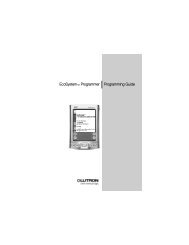
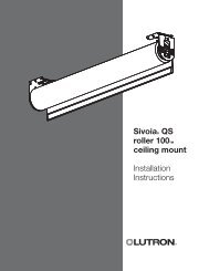
LUTRONLUTRONLUTRONLUTRONLUTRONLUTRONLUTRONLUTRONLUTRONLUTRON LUTRON LUTRONLUTRONLUTRONLUTRONLUTRONLUTRONLUTRONQS System Low-Voltage Control Wiring• System communication uses PELV (Class2: USA) low-voltage wiring.• Follow all local and national electricalcodes when <strong>install</strong>ing PELV (Class 2:USA) wiring with line voltage/mainswiring.• Each terminal accepts up to two #18AWG (1.0 mm 2 ) wires.• Total length of control link must notexceed 2,000 ft. (610 m).• Make all connections in the control unit’swallbox.• A QS system can have up to 100 zonesand 100 devices (see table below).• Wiring can be T-tapped or daisy-chained.• Wire sizes:- Two #18 AWG (1.0 mm 2 ) conductors forcontrol power.- One twisted, shielded pair of #22 AWG(1.0 mm 2 ) for data link.- Cable is available from <strong>Lutron</strong>:GRX-CBL-S-500 (non-plenum)GRX-CBLP-S-500 (plenum rated).Check compatibility in your area.QS smartpowersupply panelSivoia QSGRAFIK Eye QST-Tap Wiring ExampleGRAFIK Eye QSDaisy-Chain Wiring ExampleseeTouch QSSivoia QSseeTouch QSSystem LimitsQS Device Zone Count Device Count3-zone QS 3 14-zone QS 4 16-zone QS 6 1seeTouch QS 0 1Sivoia QS 1 1QS smart power supply panel 0 1QS smart powersupply panelRGRAFIK Eye® QS System <strong>Installation</strong> and Operation Guide 5
QS System Low-Voltage Terminal ConnectionsControl units shown in rear view1 2 3 4 5 6 H NA11 2 3 4 5 6 H NA31 2 A B C1 2 3 4A2 and A3have theirown powersupply; noterminal 2connection1 2 A B C1 2 3 4A3 powerswallstations 2,3, and 443215• Connect the terminal 1, 3, and 4connections to all control units,wallstations, and control interfaces.• Each control unit has its own powersupply. Terminate the terminal 2connection (24 V power) so that eachcontrol unit supplies power to amaximum of three wallstations. Eachwallstation should receive power fromonly one control unit.A1 powers wallstation 1 only; terminal2 terminates at wallstation 11243216QS smartpower supplypanel432143217P1443213321P1 powersshade S1only1 2 3 4 5 6 H NA21 2 A B C1 2 3 4432141 2 3 4 5 6 H NA41 2 A B C1 2 3 4Sivoia QSshadeS1No terminal 2connection betweenwallstations 4 and 5;they are powered bydifferent control unitsA4 powers wallstations5, 6, and 7RGRAFIK Eye® QS System <strong>Installation</strong> and Operation Guide 6
LUTRONLUTRONInstalling the GRAFIK Eye® QS System1.Mount a 3 1/2-in. (89 mm) deep4-gang U.S. wallbox on a dry, flatindoor surface that is accessible andallows for system programming andoperation. Allow at least 4 1/2 in.(110 mm) clearance above and belowthe faceplate to ensure proper heatdissipation. Allow 1 in. (25 mm) forfaceplate overhang on all sides.Note: 4-gang wallbox available from<strong>Lutron</strong>; P/N 241400.2.Mount the control unit in the wallboxas shown using the four screws provided.Note: Follow all local and nationalelectrical codes when <strong>install</strong>ing PELV(Class 2: USA) wiring with linevoltage/mains wiring.7.9 in.(200 mm)3.5 in.(87 mm) 3.75 in.(95 mm)Note: When tightening mountingscrews, make sure that the hingedcover and faceplate will open fully,as shown.Wall3.Apply the protective overlay to thecontrol unit. See page 14 forinstructions for naming zones.Test the Wiring1.Restore power.2.Press the top button on the lightingkeypad. The LED will light.3.Press the zone raise or lower button.Make sure the control unit is dimming allconnected loads.4.5 in.(110 mm)Faceplate overhangswallbox on all sides;allow 1 in. (25 mm)Protective overlay(apply after <strong>install</strong>ation)RGRAFIK Eye® QS System <strong>Installation</strong> and Operation Guide 7
LUTRONLUTRONZone SetupAssign Load TypeMain menuOcc sensorZone setupZone setupLoad typeHigh endLoad typeSet type usingzone controlsSaved SavedSetting Load TypesFixture load typeIncandescentMLV (magnetic low-voltage)ELV (electronic low-voltage)Hi-Lume/Eco-10Non-dimNeon/Cold cathodeTu-Wire1. Enter programming mode (see page 12).2. Use the master buttons to highlight “Zonesetup” and press the OK button toaccept.3. Use the master buttons to highlight “Loadtype”. Press the OK button to accept.4. Use the zone raise/lower buttons tochoose the load type for that zone. Seethe list below for supported load types.Press the OK button to accept.5. The info screen will display aconfirmation screen that your load typehas been saved.6. Exit programming mode (see page 12).Direct control viaGRAFIK Eye QSChoose this load type from the menuon the GRAFIK Eye QS:IncandescentMLV----Non-dim LOFO or Non-dim FOFONeon, CCTu-WireControl viapower modulePower modulePower modulePower moduleFluorescent moduleNon-dim LOFO or Non-dim FOFONeon, CCTu-WireOK1 2 3 4 5 6MasterbuttonsOKbuttonUse thezoneraise/lowerbuttons tochoose theload type forthat zone.Load Type Notes• All electronic low-voltage (ELV) lightingused with an interface must be rated forreverse phase control dimming. Before<strong>install</strong>ing an ELV light source, verify withthe manufacturer that their transformercan be dimmed. When dimming, an ELVinterface must be used with the controlunit.• Not all zones must be connected;however, connected zones must have aminimum load of 25 W.• No zone may be loaded with more than800 W.• Maximum total lighting load per unit is16 A.• Maximum total lighting load for amagnetic low-voltage (MLV) load is 2000VA or 1600 watts after transformer.Maximum load per MLV zone is 800 VA or600 watts.RGRAFIK Eye® QS System <strong>Installation</strong> and Operation Guide 8
Zone SetupSet High End or Low EndMain menuOcc sensorZone setupZone setupHigh endLow endLow endSet trim usingzone controlsZone 210%Saved SavedHigh and low end trim settings limit themaximum and minimum output of adimming zone. Trim levels are setautomatically when the load type isprogrammed. Change the high or lowend trim for a zone only if the defaultsetting needs to be adjusted.1. Enter programming mode (see page 12).2. Use the master buttons to highlight “Zonesetup” and press the OK button toaccept.3. Use the master buttons to highlight “Highend” or “Low end” (this example showslow end). Press the OK button to accept.4. Use the zone raise/lower buttons to setthe high end or low end trim for thatzone.The info screen will display each zonenumber and percentage as you adjust it.Press the OK button to accept.5. The info screen will display aconfirmation screen that your setting hasbeen saved.6. Exit programming mode (see page 12).Set Minimum Level (optional)Zone setupLow endMin levelMin levelOFFSaved SavedOK1 2 3 4 5 6MasterbuttonsOKbuttonUse thezoneraise/lowerbuttons toset the highend or lowend trim forthat zone.Some local regulations specify aminimum lighting level for dimmingzones in occupied buildings. If thispertains to you, follow these steps toset up your minimum lighting level.1. Enter programming mode (see page 12)and select “Zone setup,” then “Minlevel”. Press the OK button to accept.2. Use the master buttons to highlight“OFF” if you want your lights to go allthe way off at their minimum light level,or “10%” if you want that to be theminimum light level. Press the OK buttonto accept.Note: Non-dim loads will turn offregardless of the minimum level setting.3. The info screen will display aconfirmation screen that your minimumlevel has been saved.4. Exit programming mode (see page 12).RGRAFIK Eye® QS System <strong>Installation</strong> and Operation Guide 9
Preprogrammed Button FunctionalityThe GRAFIK Eye QS System controls lights without special programming. The factorydefaults for the lighting column buttons are shown below for both dimmable and nondimzones. See pages 15 through 17 for methods for changing scene settings.<strong>Lighting</strong> Column Button Preprogramming(Factory Default: Dimmable Loads)Scene 1: All lights to 100%Scene 2: All lights to 75%Scene 3: All lights to 50%Scene 4: All lights to 25%<strong>Lighting</strong> Column Button Preprogramming(Factory Default: Non-Dim Loads)Scene 1: All lights OnScene 2: All lights OnScene 3: All lights OnScene 4: All lights OnShade Column Button Preprogramming(Factory Default: Sivoia QS shades)All shades fully openAll shades to 50%All shades fully closedLower/Raise all shadesRGRAFIK Eye® QS System <strong>Installation</strong> and Operation Guide 10
General FunctionalityOKThe info screen goes blank after 20seconds if there is no button press orfading.The master buttons also activate the infoscreen. These buttons temporarily raise orlower all dimmable lights (except thoseprogrammed as unaffected in the currentscene). Adjustments are temporary and donot affect scene programming.The OK button activates the info screen,which then shows the current scene and itsfade time.OKInfo screen: see example screens belowMaster buttons temporarily raise or lowerall lights (except unaffected, shades, andnon-dim zones) on this GRAFIK Eye QSunitScene 1Master raiseMaster lowerThe timeclock button activates the infoscreen and displays the current time, thenext event scheduled to occur, and whatthat next event is. Pressing a second timedisplays the location and thesunrise/sunset times.OK button activates the info screen,which shows the current scene’s fadetime. In Save Always mode, allows fadetime adjustment. InScene: 1Save by OKmode, pressinga second timeallows zoneadjustment;pressing a thirdtime allows fadeadjustment.Adjust fade03 secondsTimeclock button displays the currenttime and the next scheduled event.Pressing when in Program modefunctions as a“back” button.11:23 AM FriNext: 5:00 PMScene 1RGRAFIK Eye® QS System <strong>Installation</strong> and Operation Guide 11
General Functionality: Programming ModeEntering and Exiting Programming ModeMain menuTimeclockScene setupInfo screen displaywhen you enterprogramming modeScene 1Fade time3 secondsInfo screen displaywhen you exitprogramming modeTo enter programming mode:Press and hold simultaneously the top andbottom buttons on the lighting column for 3seconds.The LEDs in the lighting buttonswill scroll from top to bottom, confirmingthat you are in programming mode, and theinfo screen will display the main menu.To exit programming mode:Press and hold simultaneously the top andbottom buttons on the lighting column for3 seconds. The info screen will go toScene 1.OKMaster buttonsOK buttonTimeclock buttonPress and hold the top andbottom buttons for 3 secondsto enter or exit programmingmodeNavigating Menus in Programming ModeMaster ButtonsThe master buttons allow you to move through the menuchoices. The current choice is highlighted on the info screen.OK ButtonThe OK button chooses the current highlighted menu choice.This will either take you to the next menu or accept a setting youhave selected.Timeclock ButtonThe timeclock button functions as a “back” button duringprogramming mode. Pressing the timeclock button takes youback one step in the current menu. Pressing it repeatedly willeventually return you to the main menu, but will not exitprogramming mode.RGRAFIK Eye® QS System <strong>Installation</strong> and Operation Guide 12
Zone Button OperationEach column of buttons represents onezone of lights. Pressing any button on acolumn turns on the info screen anddisplays the zone’s current light level andcurrent energy savings.Pressing the raise and lower buttons on azone causes different actions dependingon zone type (see below).1 2 3 4 5Dimmable zones:• Press and hold to raise/lower all lights in azone; release to stop• Press raise or lower to stop a zone that isfading• Raising lights from off to full on or loweringfrom full on to off takes 5 seconds• Press raise and lower simultaneously totoggle between full on and offNon-dim zones:• Press raise to take light zones to full on• Press lower to take light zones to off2 3LEDs indicate light levelNote: See page 18 for anexplanation of the LEDdisplay for each type ofload in a zone.Zone RaiseZone LowerRGRAFIK Eye® QS System <strong>Installation</strong> and Operation Guide 13
Zone Button OperationName a ZoneMain menuOcc sensorZone Scene setupZone setupMin levelLabelSelect zone:Zone 2Label zone 2CustomLabel zone 21 / 121: AA1. Enter programming mode (see page 12).2. Use the master buttons to highlight “Zone setup”and press the OK button to accept.3. Use the master buttons to highlight “Label” andpress the OK button to accept.4. Use the master buttons to change the zonenumber to your desired zone. Custom zone labelswill appear if previously set. Press the OK buttonto accept.5. Use the master buttons to highlight “Custom” andpress the OK button to accept. Or, highlight“Default” to return the zone label to the default(e.g., Zone 1).6. Use the master buttons to scroll through thecharacters (lowercase and uppercase letters, plusnumbers 0-9). The character you are currentlychanging will be underlined on the screen. PressOK to select the character you want, then repeatfor all available characters. Choose a space (nocharacter) and press OK for any remainingcharacters. Press the OK button to accept.Note: Custom zone labels will always begin withthe zone number and a colon (e.g., 1:Uplights).7. The info screen will display a confirmation screenthat your name has been saved.8. Exit programming mode (see page 12).OKMasterbuttonsOKbuttonSaved SavedRGRAFIK Eye® QS System <strong>Installation</strong> and Operation Guide 14
Quick Scene ProgrammingSave Always ModeThe default save mode (see page 28) isSave Always. This mode allows you toquickly set scenes on the lighting columnwithout entering program mode.1.Press the button for the scene you wantto set; its LED will light and the lights willgo to the current settings.2.Use the zone raise/lower buttons to setall lights to the desired levels. Press theOK button.3.To set the fade time for this scene, pressthe OK button, then use the masterbuttons to set the desired fade time.Press the OK button to save.Note: Using the master buttons to raiseor lower lighting settings is still temporaryin Save Always mode.1 2 3 4 5 61. Press the lighting column scene buttonyou wish to program.2. Use the zone raise/lower buttons to setlight levels.OK3. Use the master buttons to set fade time.RGRAFIK Eye® QS System <strong>Installation</strong> and Operation Guide 15
Scene SetupProgram a SceneMain menuTimeclockScene setupScene setupLevelsLabelsScene setupScene 1Scene 13 Set seconds zonesScene 1Adjust fade3 seconds1. Enter programming mode (see page 12).2. Use the master buttons to highlight “Scene setup” andpress the OK button to accept.3. Use the master buttons to select “Levels” to adjust lightingand/or window treatment levels. Press the OK button toaccept. Us the master buttons to select the scene numberof your desired scene. Press the OK button to accept.4. Set each zone to the desired light level for this scene usingthe zone raise/lower buttons. The info screen will displaythe zone and percentage as you adjust it.To set a zone as unaffected, lower the light levels all theway to off, then hold the zone lower button for 3 seconds.When all zones are at the desired level, press the OKbutton to accept.5. Use the master buttons to set the fade time for this scene.Press the OK button to accept.6. Press the button on a shade column that will take thewindow treatments assigned to that shade column to thelevel you want for this scene. Repeat for any additionalshade columns. Press the OK button to accept. Or, if youdo not have or do not wish to set shade groups for thisscene, press OK.7. The info screen will display a confirmation screen that yourscene has been saved.8. Exit programming mode (see page 12).OK1 2 3 4 5MasterbuttonsOKbuttonScene 1Set shadegroups2 3Zone RaiseZone LowerSaved SavedRGRAFIK Eye® QS System <strong>Installation</strong> and Operation Guide 16
Scene SetupName a SceneMain menuOcc sensorScene setupScene setupLevelsLabelsSelect scene:Scene 1Label scene 1Custom1. Enter programming mode (see page 12).2. Use the master buttons to highlight “Scene setup”and press the OK button to accept.3. Use the master buttons to highlight “Labels” andpress the OK button to accept.4. Use the master buttons to change the scenenumber to your desired scene. Press the OKbutton to accept.5. Use the master buttons to highlight “Custom” andpress the OK button to accept.6. Use the master buttons to scroll through thecharacters (lowercase and uppercase letters, plusnumbers 0-9). The character you are currentlychanging will be underlined on the screen. PressOK to select the character you want, then repeatfor all available characters. Choose a space (nocharacter) and press OK for any remainingcharacters. Press the OK button to accept.7. The info screen will display a confirmation screenthat your name has been saved.8. Exit programming mode (see page 12).OKMasterbuttonsOKbuttonLabel scene 11 / 111: AASaved SavedRGRAFIK Eye® QS System <strong>Installation</strong> and Operation Guide 17
LED Displays for <strong>Lighting</strong> LevelsDimmable LightsNon-Dim LightsOff1-17%18-34%35-51%52-68%69-85%86-99%On/100%Unaffected(lights are not affectedby scene buttonor master raise/lower)Legend:LED litLED offRGRAFIK Eye® QS System <strong>Installation</strong> and Operation Guide 18
Adjusting Window Treatment SettingsSetting LimitsNote: Entering Limit Setup modemay cause window treatments tomove approximately 8 inches upor down. Be sure that eachwindow treatment is positionedso that the fabric can safelymove 8 inches up or downbefore entering Limit Setupmode.1.On any shade column,press and holdsimultaneously the topand raise buttons. TheLEDs next to the topand bottom buttons willcycle.Note: At any time whilein Limit Setup mode,you can move allwindow treatmentstogether to their currentopen limit by doubletappingthe top button,or to their current closelimit by double-tappingthe bottom button.Note: Once EDUs (electronic drive unitsof the window treatment) have beenassigned to shade columns, limits can beset for an EDU only using the shadecolumn it is assigned to, and a shadecolumn can set limits only for those EDUsassigned to it.2.Select the EDU you want to to adjustusing the top button on the shadecolumn. Each time you press and releasethe top button, a different EDU that isassigned to that shade column will openand close in an 8-inch range to indicate itis selected. Press the top button until theEDU for the window treatment you wishto adjust moves. (You can also use thebottom button, which moves through theassigned EDUs in the opposite order.)3. Adjust the currently selectedEDU to the desired level forthe open limit (the maximumthe window treatment isallowed to open) using theraise and lower buttons.4.Press and hold the top button on theshade column for 5 seconds to store thecurrent position as the open limit. TheLED next to the top button will flashquickly for 2 seconds.5.Adjust the currently selected EDU to thedesired level for the close limit (themaximum the window treatment isallowed to close) using the raise andlower buttons.6.Press and hold the bottom button on theshade column for 5 seconds to store thecurrent position as the close limit.TheLED next to the bottom button will flashquickly for 2 seconds.7.Repeat steps 2 through 6 to set the openand close limits for each windowtreatment assigned to the shade column.8.Press and hold simultaneously the topand raise buttons on the shade column toexit Limit Setup mode.RGRAFIK Eye® QS System <strong>Installation</strong> and Operation Guide 19
Adjusting Window Treatment SettingsAssigning EDUs to Shade ColumnsNote: Entering Assignment modewill cause the window treatmentsto move between their open andclose limits. Be sure that theopen and close limits have beenset correctly.1. Press and holdsimultaneously the topand bottom buttons onthe shade column for 5seconds to enterprogramming mode.The LEDs next to thebuttons will flash onceper second. EDUs(electronic drive units ofthe window treatments)assigned to that shadecolumn will move totheir close limit, andEDUs not assigned tothat shade column willmove to their openlimit.2.To assign an EDU to the shade columnthat is program mode, use one of thefollowing methods:- Press and release the top button on theshade column that is in program mode.Each time you press and release the topbutton, a different EDU that is assigned tothat shade column will open and close inan 8-inch range. Press the top buttonuntil the EDU you wish to assign to theshade column moves. (You can also usethe bottom button, which moves throughthe EDUs in the opposite order.)- Or, press and release any button on anEDU to toggle between unassignmentand assignment for that EDU’s windowtreatment to the shade column.Assign or unassign the currently selectedEDU to the shade column using the raiseand lower buttons.Lower button(assign)Raise button(unasssign)The lower button assigns the selectedEDU.The raise button unassigns the selectedEDU.3.Check window treatment assignments:EDUs for window treatments assigned tothe shade column will be at their closelimit, and EDUs for window treatmentsnot assigned to the shade column will beat their open limit.4.Press and hold simultaneously the topand bottom buttons on the shade columnfor 5 seconds to exit Assignment mode.The LEDs next to the buttons will stopflashing, and the EDUs assigned to theshade column will return to their levelsbefore entering Assignment mode.Note: Once you have assigned windowtreatments to a shade column, you willnotice the following additionalfunctionality:- When some or all EDUs assigned to ashade column are moving, press andrelease the top, middle, or bottombutton to immediately stop all assignedEDUs.- The position that each EDU moves towhen the middle button is pressed isnow reprogrammable. See PresetAdjustment on page 21.- No matter how or from where theirmovement is commanded, whenever allthe assigned EDUs come to a stop andmatch their programmed positions forone of the buttons in the shade column,the LED next to that button willautomatically light up.RGRAFIK Eye® QS System <strong>Installation</strong> and Operation Guide 20
Adjusting Window Treatment SettingsPreset Adjustment: Simple Method1. Use the raise and lowerbuttons on the shadecolumn to set all EDUs(electronic drive units ofthe window treatments)to the desired presetlevels.2. Press and hold themiddle button on theshade column for 5seconds to save theEDU preset positions.The LED next to thebutton will flash andthen light continuously,indicating the presethas been stored.Note: Once EDU presets have beenassigned to buttons on a shade column,those presets are accessible for an EDUonly using the shade column it isassigned to, and a shade column canaccess preset levels only for those EDUsassigned to it.Preset Adjustment: Advanced MethodNote: The advanced method for adjustingpresets is needed only if you wish to havethe window treatments assigned to theshade column set at different positions inthe preset. If, however, you wish all thewindow treatments in the group to belined up with one another in the preset,you should use the Simple Method at left.Note: Entering Assignment mode willcause the window treatments to movebetween their open and close limits. Besure that the open and close limits havebeen set correctly.1. On the shade columnwhose preset you wishto adjust, press andhold simultaneously thetop and bottombuttons. The LEDs nextto the buttons will flash.EDUs (electronic driveunits) for the assignedwindow treatments willmove to their closedlimits, and EDUs forunassigned windowtreatments will move totheir open limits.2.Press and release the middle button onthat shade column. The adjacent LED willblink rapidly. EDUs for assigned windowtreatments will automatically move totheir current preset settings.3. Use the raise and lowerbuttons to move all EDUsfor assigned windowtreatments together to thedesired preset setting.4.To move an EDU individually to itsdesired preset setting, select the EDUusing the top button on the shadecolumn. Each time you press and releasethe top button, a different EDU that isassigned to that shade column will openand close in an 8-inch range. Pressrepeatedly until the EDU for the windowtreatment you wish to adjust moves.Adjust that EDU to the desired heightusing the raise and lower buttons.Repeat this step for all assigned EDUs.5.Once you are satisfied that all theassigned EDUs are set to the positionsyou want to assign as the preset, pressand hold the middle button on the shadecolumn for 5 seconds. The preset will besaved.6.Press and hold simultaneously the topand bottom buttons on the shade columnfor 5 seconds to exit to normal mode.The LEDs next to the buttons will stopflashing.RGRAFIK Eye® QS System <strong>Installation</strong> and Operation Guide 21
Adjusting Window Treatment SettingsMain menuZone setupShade labelsSelect shade grp:Shade grp 1Label shade grp:CustomName a Group of Window Treatments1. Enter programming mode (see page 12).2. Use the master buttons to highlight “Shade labels” and pressOKthe OK button to accept.3. Use the master buttons to select your desired shade group.Press the OK button to accept.4. Use the master buttons to highlight “Custom” and press the OK button to accept.5. Use the master buttons to scroll through the characters (lowercase and uppercaseletters, plus numbers 0-9). The character you are currently changing will beunderlined on the screen. Press OK to select the character you want, then repeatfor all available characters. Choose a space (no character) and press OK for anyremaining characters. Press the OK button to accept.6. The info screen will display a confirmation screen that your name has been saved.7. Exit programming mode (see page 12).MasterbuttonsOKbuttonLabel shade grp 11 / 111: AASaved SavedRemotely Restore EDUs to FactoryDefaultsWarning! Restoring an EDU(electronic drive unit for a windowtreatment) to its factory defaultswill erase any previousprogramming or assignments youhave made for that EDU.Note: Entering this mode maycause window treatments tomove approximately 8 inches upor down. Be sure that eachwindow treatment is positionedso that the fabric can safelymove 8 inches up or downbefore entering this mode.1. On any shade column,press and holdsimultaneously the topand lower buttons.The LED next to thetop button will flash.2. Press and hold the topbutton for 5 seconds.All shade columnLEDs will blink rapidly.3.Select the EDU you want to restore tofactory defaults using the top button onthe shade column. Each time you pressand release the top button, a differentEDU in your system will open and closein an 8-inch range to indicate it isselected. Press the top button until theEDU for the window treatment you wishto restore to factory defaults moves. (Youcan also use the bottom button, whichmoves through the assigned EDUs in theopposite order.)4.Press and hold simultaneously the raiseand lower buttons for 5seconds to restore the movingshade to factory defaults.5.Repeat steps 3 and 4 to restore factorydefaults to any other window treatments.6.Press and hold simultaneously the topand lower buttons on the shade columnto exit this mode.RGRAFIK Eye® QS System <strong>Installation</strong> and Operation Guide 22
Timeclock OperationSet Time and DateMain menuTimeclockScene setupTimeclockHolidayDelete Time & event dateSet formatDel: 12 00 HrSet time1. Enter programming mode (see page 12).2. Use the master buttons to highlight “Timeclock”and press the OK button to accept.3. Use the master buttons to highlight “Time & date”and press the OK button to accept.4. Use the master buttons to select between “12 Hr”and “24 Hr” format for time display and press theOK button to accept.5. Use the master buttons to select the current hourand press the OK button to accept. Repeat for thecurrent minutes.6. Use the master buttons to highlight the currentyear and press the OK button to accept. Repeatfor the current month and date.7. The info screen will display a confirmation screenthat your time and date have been saved.8. Exit programming mode (see page 12).OKMasterbuttonsOKbutton08: 00 AMSet time08 : 00 30 AMSet dateSet dateSet dateDel: 2007March17Saved SavedRGRAFIK Eye® QS System <strong>Installation</strong> and Operation Guide 23
Timeclock OperationSet LocationMain menuTimeclockScene setupTimeclockTime & dateDelete Location eventLocation byCountry, CityLat/LongitudeCountry08 : USA 00StatePennsylvaniaCityPhiladelphia1. Enter programming mode (see page 12).2. Use the master buttons to highlight“Timeclock” and press the OK button toaccept.3. Use the master buttons to highlight“Location” and press the OK button toaccept.4. Use the master buttons to choose to setyour location by either country and cityor latitude and longitude. Press the OKbutton to accept.5. Use the master buttons to highlight thecountry and press the OK button toaccept. Repeat for the state and closestcity.6. The info screen will display aconfirmation screen that your time anddate have been saved.7. Exit programming mode (see page 12).Set Daylight Saving TimeTimeclockLocationDelete Set DST eventUse DST?Del: 00 YESOKMasterbuttonsOKbutton1. Enter programming mode (see page12) and select “Timeclock”. Use themaster buttons to highlight “SetDST” and press the OK button toaccept.2. Use the master buttons to highlight“YES” if your location observesdaylight saving time, or “NO” if itdoes not. Press the OK button toaccept.3. If yes, use the master buttons tochoose either “USA 2007” (thesecond Sunday in March to the firstSunday in November), or “Other.”For “Other,” follow the screens toset start and end dates and amountof time.4. Press the OK button to accept. Theinfo screen will display aconfirmation screen that your timeand date have been saved.5. Exit programming mode (see page12).Saved SavedRGRAFIK Eye® QS System <strong>Installation</strong> and Operation Guide 24
Timeclock OperationAdd an EventMain menuTimeclockScene setupTimeclockView eventsDelete Add eventsAddAddTime of dayAddMondayDel: 08 00 AMAddScene Scene 11. Enter programming mode (see page 12).2. Use the master buttons to highlight “Timeclock”and press the OK button to accept.3. Use the master buttons to highlight “Add events”and press the OK button to accept.4. Use the master buttons to select the day of theweek for this event; press the OK button toaccept.5. Use the master buttons to select the type of event(fixed time of day, or relative to sunrise or sunset);press the OK button to accept.6. For a fixed-time event, use the master buttons toselect the hour for your event to begin; press theOK button to accept. Repeat for the minutes.For a relative time event, use the master buttonsand the OK button to set the hour, then theminutes relative to sunrise or sunset (maximum of1 hour 59 minutes before or after sunrise orsunset).7. Use the master buttons to select the scene youwish to activate for this event.For a timeclock event involving only shades, scrollthrough the scenes to find the group of shadesand the action (1, 2, or 3; open, preset, or close)you want to add to the timeclock event.Or, press the button on the shade column thatproduces the action you want to add to thistimeclock event.Press the OK button to accept.8. The info screen will display a confirmation screenthat your event has been saved.9. Exit programming mode (see page 12).OKMasterbuttonsOKbuttonSaved SavedRGRAFIK Eye® QS System <strong>Installation</strong> and Operation Guide 25
Timeclock OperationDelete an EventMain menuTimeclockScene setupTimeclockCopy scheduleDelete eventsDeleteMondayDelete8:00 AMScene 5Delete?Saved Saved01/031. Enter programming mode (see page 12).2. Use the master buttons to highlight“Timeclock” and press the OK button toaccept.3. Use the master buttons to highlight“Delete events” and press the OK buttonto accept.4. Use the master buttons to select the dayof the week (or holiday) when the eventoccurs; press the OK button to accept.5. Use the master buttons to select theevent to delete; press the OK button toaccept.6. A screen will appear, verifying you wish todelete the event. Press the OK button toaccept and delete; otherwise, press thetimeclock button to go back.7. The info screen will display aconfirmation screen that your event hasbeen deleted.8. Exit programming mode (see page 12).View an EventTimeclockDelete View events eventsAdd eventsView eventsMonday MondayView8:00 AMScene 501/03OKMasterbuttonsOK buttonTimeclockbutton1. Enter programming mode (see page 12),select “Timeclock,” and select “Viewevents”.2. Use the master buttons to select the dayof the week (or holiday) when the eventoccurs; press the OK button to accept.3. Use the master buttons to select theevent to view; press the OK button toaccept.4. Press the OK button to return to theTimeclock menu.5. Exit programming mode (see page 12).RGRAFIK Eye® QS System <strong>Installation</strong> and Operation Guide 26
Timeclock OperationSet a HolidayTimeclockDelete scheduleHolidayHolidayAdd Set holiday eventDelete holidayAddFebAdd11. Enter programming mode (see page 12).2. Use the master buttons to highlight“Timeclock” and press the OK button toaccept.3. Use the master buttons to highlight“Holiday” and press the OK button toaccept.4. Use the master buttons to select “Setholiday” and press the OK button toaccept.5. Use the master buttons to set the monthof the holiday and press the OK button toaccept. Repeat for the date.6. The info screen will display aconfirmation screen that your holiday hasbeen set.7. Exit programming mode (see page 12).OKMasterbuttonsOKbuttonMonday Feb 14Saved SavedDelete a HolidayHolidaySet holidayDelete holidayFeb 14MondayDelete?1. Enter programming mode (see page 12),select “Timeclock,” select “Holiday,” andselect “Delete holiday”.2. Use the master buttons to select theholiday you wish to delete and press theOK button to accept.3. The info screen will display aconfirmation screen that your event hasbeen deleted.4. Exit programming mode (see page 12).Saved DeletedRGRAFIK Eye® QS System <strong>Installation</strong> and Operation Guide 27
Set Save ModeMain menuScene setupSave modeSave modeSave always1. Enter programming mode (see page 12).2. Use the master buttons to highlight “Savemode” and press the OK button toaccept.3. Use the master buttons to highlight thesave mode you would like. The savemodes are listed and explained below.4. Press the OK button. The info screen willdisplay a confirmation screen that yoursave mode has been saved.5. Exit programming mode (see page 12).OKMasterbuttonsOKbuttonSaved SavedSave ModesSave always (default mode) . . Quick scene programming mode; automatically save changes made to to lighting levels or fade time(master raise/lower changes are temporary)Save by OK . . . . . . . . . . . . . . Zone adjustments are temporary unless the OK button precedes themSave never . . . . . . . . . . . . . . . Do not save any temporary changes to lighting levels or fade timeFour scenes . . . . . . . . . . . . . . Zone raise/lower buttons are disabled (typically used for rented spaces)Master raise/lower buttons, wallstations, and IR receiver are still enabled for adjustment of light level,but these changes are not savedButton disable . . . . . . . . . . . . Only the timeclock button, IR receiver, and wallstations can be used to make temporary changes(typically used in a public space)Note: Off scene can be changed only through scene setup in program mode. Save modes will change only the fade time in Offscene settings.RGRAFIK Eye® QS System <strong>Installation</strong> and Operation Guide 28
Set Up Occupant SensorMain menuSave modeOcc sensorOccupiedScene 1UnoccupiedManual offSaved Saved1. Enter programming mode (see page 12).2. Use the master buttons to highlight “Occ sensor” and press theOK button to accept.3. Use the master buttons to select the scene you wish to activatewhen the room is occupied.For an occupant sensor setting involving only shades, scrollthrough the scenes to find the group of shades and the action(1, 2, or 3; open, preset, or close) you want to set.Or, press the button on the shade column that produces theaction you want to add to this timeclock event.If your local lighting code requires it, you may also select“Manual on,” which means the occupant sensor will notautomatically turn the lights on when someone enters a room.Instead, a button must be pressed manually.4. Press OK to accept your choice.5. Use the master buttons to select the scene you wish to activatewhen the room is unoccupied.For an occupant sensor setting involving only shades, scrollthrough the scenes to find the group of shades and the action(1, 2, or 3; open, preset, or close) you want to set.Or, press the button on the shade column that produces theaction you want to add to this timeclock event.You may also select “Manual off,” which means the occupantsensor will not trigger an action when the room is unoccupied.6. Press OK to accept your choice. The info screen will display aconfirmation screen that your occupant sensor settings havebeen saved.7. Exit programming mode (see page 12).OKMasterbuttonsOKbuttonOccupied and Unoccupied ModesOccupied, contact closing . . . . . . The occupied scene occurs when an occupant sensor or contact closure connected to theoccupant sensor input closes.Unoccupied, contact opening . . . The unoccupied scene occurs when an occupant sensor or contact closure connected to theoccupant sensor input opens.RGRAFIK Eye® QS System <strong>Installation</strong> and Operation Guide 29
Activate System AccessoriesOnce your control unit is programmed,you will need to activate any accessoriesor interfaces that are a part of thesystem. Refer to the instructions thataccompanied those devices to set themup for proper communication with theGRAFIK Eye QS control unit.Faceplate RemovalThe faceplates may need to be removedto change the color or to write in zonelabels. To remove either faceplate, open itfully (flush to the wall), and pull up (for thetop faceplate) or down (for the bottomfaceplate) to pull the hinges out of theirslots.Replace by sliding the hinges back intotheir slots.Pull up to removetop faceplate1 2 3 4 5 6OKPull down to removebottom faceplateRGRAFIK Eye® QS System <strong>Installation</strong> and Operation Guide 30
TroubleshootingSymptomUnit does not control loadsUnit does not turn lights onLEDs on front of unit are not ONMCB/breaker is trippingUnit does not control loadZONE control does not work1 or more zones are "full on"when any scene is onand zone intensity is notadjustableA Zone control affects morethan one zoneKeypad buttons are not workingKeypad LEDs are not trackingFaceplate is warmPossible CausesBreaker/MCB is offLong fade timeLow zone settingsMiswireSystem short circuitSystem overloadMiswireDisconnected wireBurned-out lampsMiswireShorted triacMiswireMiswire or loose connection on lowvoltagelinkWallstation programming is incorrectNormal operationRemedySwitch breaker/MCB onSet fade time to 0 secondsReprogram scenes to a higher intensityCheck wiringFind and correct shortsMake sure unit is not overloaded(2000 W max)Check wiringConnect zone wires to loadsReplace bad lampsMake sure loads are connected to theright zonesReplace control unitCheck for shorts between zone outputsTighten loose connections at PELVterminals on all units and other devices inthe systemCheck the keypad function andprogramming on the unitsSolid-state controls dissipate about 2%of the connected load as heat.RGRAFIK Eye® QS System <strong>Installation</strong> and Operation Guide 31
Troubleshooting (continued)SymptomUnit does not allow scene change orzone adjustmentsScreen is offOccupant sensor input does not workTimeclock events do not occurSunrise or sunset events do not occur atthe correct timePossible CausesUnit in wrong save modeKeypad in system has locked the unitNormal operationMiswireIncorrect programmingInput closure/opening is not occurringTimeout on occupant sensor is set toolongTimeclock is disabledTime is not set correctlyDate is not set correctlyLocation is not set correctlyHoliday schedule is in effectRemedyChange to correct save modeCheck programming and state ofkeypadsScreen turns off after 20 secondsCheck wiring on contact closure inputRe-program the occupied andunoccupied states of the inputCheck that the input device is openingand closing properlySet the occupant sensor timeout to ashorter timeEnable the timeclockSet the timeSet the dateSet the latitude and longitude correctlyRemove the holiday schedule from yourprogrammingRGRAFIK Eye® QS System <strong>Installation</strong> and Operation Guide 32
Troubleshooting (continued) - Window Treatment FunctionsSymptomPossible CausesRemedyEDU (electronic drive unit of the windowtreatment) will not moveEDU (electronic drive unit of the windowtreatment) does not fully open or fullycloseWindow treatment moves in the oppositedirection when raise/lower buttons arepushedKeypad LEDs are off and keypad will notcontrol any window treatmentKeypad LEDs are on but keypad will notcontrol any window treatmentKeypad does not operate all the windowtreatments it is assigned toWindow treatments in a room move ontheir ownEDU is not poweredWindow treatment fabric is caught onsomethingEDU is not assigned to a keypadPresets have been set incorrectlyLimits have been set incorrectlyWindow treatment fabric is caught onsomethingOpen and close limits have been reversedNo power is going to keypadAll presets are set to the same heightCommunications link is not wired to theEDUEDU has been unassigned from keypadEDU has been unassigned from keypadAll presets are set to the same heightEDU is not wired correctlyKeypad is not wired correctlyEDUs are assigned to a keypad inanother roomCheck EDU powerCheck and unbind window treatmentfabricAssign the EDU to a keypadTry using raise/lower buttons on keypadSet limits correctlyCheck and unbind window treatmentfabricSet limits correctlyCheck and wire power to keypadTry using raise/lower buttons on keypadCheck and wire the EDU linkReassign the EDU to the keypadReassign the EDU to the keypadTry using raise/lower buttons on keypadCheck and rewire EDUCheck and rewire keypadReassign the EDU to the correct keypadRGRAFIK Eye® QS System <strong>Installation</strong> and Operation Guide 33
Menu OptionsTimeclockView eventsSee page 26Add eventsCopy all timeclock events from one dayto anotherCopy scheduleCopy all timeclock events from one dayto anotherDelete eventsSee page 26Delete scheduleDelete all timeclock events from aspecified dayHolidaySee page 27Time & dateSee page 23LocationSee page 24Set DSTSee page 24Enable/DisableEnable or disable timeclock eventsScene setupLevelsSee page 16LabelsSee page 17Save modeSee page 28Occ sensorSee page 29Zone setupLoad typeSee page 8High endSee page 9Low endSee page 9Min levelSee page 9LabelSee page 14Shade labelsSee page 22IREnabledEnable control of the GRAFIK Eye by IR (remote control palm pilot, wired IR device,etc.)DisabledDisable control of the GRAFIK Eye by IR (remote control palm pilot, wired IR device,etc.)BacklightOffTurn off the green backlights on the scene and shade buttonsOnTurn on the green backlights on the scene and shade buttonsDiagnosticsDiagnostics are for advanced use only. For help, contact <strong>Lutron</strong> TechnicalSupport.Device serialDisplays the serial number of the GRAFIK EyeLink detailsDisplays diagnostic information for all devices wired on the linkCode revDisplays the software versions of the different components within the GRAFIK EyeUSB statusDisplays diagnostic information for the GRAFIK Eye’s USBReset USBResets the USB module on the GRAFIK Eye (used if it is having troublecommunicating)RGRAFIK Eye® QS System <strong>Installation</strong> and Operation Guide 34
Warranty<strong>Lutron</strong> Electronics Co., Inc.One Year Limited WarrantyFor a period of one year from the date of purchase, andsubject to the exclusions and restrictions described below, <strong>Lutron</strong>warrants each new unit to be free from manufacturing defects.<strong>Lutron</strong> will, at its option, either repair the defective unit or issue acredit equal to the purchase price of the defective unit to theCustomer against the purchase price of comparable replacementpart purchased from <strong>Lutron</strong>. Replacements for the unit providedby <strong>Lutron</strong> or, at its sole discretion, an approved vendor may benew, used, repaired, reconditioned, and/or made by a differentmanufacturer.If the unit is commissioned by <strong>Lutron</strong> or a <strong>Lutron</strong> approvedthird party as part of a <strong>Lutron</strong> commissioned lighting controlsystem, the term of this warranty will be extended, and anycredits against the cost of replacement parts will be prorated, inaccordance with the warranty issued with the commissionedsystem, except that the term of the unit's warranty term will bemeasured from the date of its commissioning.EXCLUSIONS AND RESTRICTIONSThis Warranty does not cover, and <strong>Lutron</strong> and its suppliers are notresponsible for:1. Damage, malfunction or inoperability diagnosed by <strong>Lutron</strong> or a<strong>Lutron</strong> approved third party as caused by normal wear andtear, abuse, misuse, incorrect <strong>install</strong>ation, neglect, accident,interference or environmental factors, such as (a) use ofincorrect line voltages, fuses or circuit breakers; (b) failure to<strong>install</strong>, maintain and operate the unit pursuant to the operatinginstructions provided by <strong>Lutron</strong> and the applicable provisionsof the National Electrical Code and of the Safety Standards ofUnderwriter's Laboratories; (c) use of incompatible devices oraccessories; (d) improper or insufficient ventilation; (e)unauthorized repairs or adjustments; (f) vandalism; or (g) anact of God, such as fire, lightning, flooding, tornado,earthquake, hurricane or other problems beyond <strong>Lutron</strong>'scontrol.2. On-site labor costs to diagnose issues with, and to remove,repair, replace, adjust, re<strong>install</strong> and/or reprogram the unit orany of its components.3. Equipment and parts external to the unit, including those soldor supplied by <strong>Lutron</strong> (which may be covered by a separatewarranty).4. The cost of repairing or replacing other property that isdamaged when the unit does not work properly, even if thedamage was caused by the unit.EXCEPT AS EXPRESSLY PROVIDED IN THIS WARRANTY,THERE ARE NO EXPRESS OR IMPLIED WARRANTIES OF ANYTYPE, INCLUDING ANY IMPLIED WARRANTIES OF FITNESS FORA PARTICULAR PURPOSE OR MERCHANTABILITY. LUTRONDOES NOT WARRANT THAT THE UNIT WILL OPERATE WITHOUTINTERRUPTION OR BE ERROR FREE.NO LUTRON AGENT, EMPLOYEE OR REPRESENTATIVE HASANY AUTHORITY TO BIND LUTRON TO ANY AFFIRMATION,REPRESENTATION OR WARRANTY CONCERNING THE UNIT.UNLESS AN AFFIRMATION, REPRESENTATION OR WARRANTYMADE BY AN AGENT, EMPLOYEE OR REPRESENTATIVE ISSPECIFICALLY INCLUDED HEREIN, OR IN STANDARD PRINTEDMATERIALS PROVIDED BY LUTRON, IT DOES NOT FORM A PARTOF THE BASIS OF ANY BARGAIN BETWEEN LUTRON ANDCUSTOMER AND WILL NOT IN ANY WAY BE ENFORCEABLE BYCUSTOMER.IN NO EVENT WILL LUTRON OR ANY OTHER PARTY BELIABLE FOR EXEMPLARY, CONSEQUENTIAL, INCIDENTAL ORSPECIAL DAMAGES (INCLUDING, BUT NOT LIMITED TO,DAMAGES FOR LOSS OF PROFITS, CONFIDENTIAL OR OTHERINFORMATION, OR PRIVACY; BUSINESS INTERRUPTION;PERSONAL INJURY; FAILURE TO MEET ANY DUTY, INCLUDINGOF GOOD FAITH OR OF REASONABLE CARE; NEGLIGENCE, ORANY OTHER PECUNIARY OR OTHER LOSS WHATSOEVER), NORFOR ANY REPAIR WORK UNDERTAKEN WITHOUT LUTRON'SWRITTEN CONSENT ARISING OUT OF OR IN ANY WAY RELATEDTO THE INSTALLATION, DEINSTALLATION, USE OF OR INABILITYTO USE THE UNIT OR OTHERWISE UNDER OR IN CONNECTIONWITH ANY PROVISION OF THIS WARRANTY, OR ANY AGREEMENTINCORPORATING THIS WARRANTY, EVEN IN THE EVENT OF THEFAULT, TORT (INCLUDING NEGLIGENCE), STRICT LIABILITY,BREACH OF CONTRACT OR BREACH OF WARRANTY OF LUTRONOR ANY SUPPLIER, AND EVEN IF LUTRON OR ANY OTHERPARTY WAS ADVISED OF THE POSSIBILITY OF SUCH DAMAGES.NOTWITHSTANDING ANY DAMAGES THAT CUSTOMER MIGHTINCUR FOR ANY REASON WHATSOEVER (INCLUDING, WITHOUTLIMITATION, ALL DIRECT DAMAGES AND ALL DAMAGES LISTEDABOVE), THE ENTIRE LIABILITY OF LUTRON AND OF ALL OTHERPARTIES UNDER THIS WARRANTY ON ANY CLAIM FORDAMAGES ARISING OUT OF OR IN CONNECTION WITH THEMANUFACTURE, SALE, INSTALLATION, DELIVERY, USE, REPAIR,OR REPLACEMENT OF THE UNIT, OR ANY AGREEMENTINCORPORATING THIS WARRANTY, AND CUSTOMER'S SOLEREMEDY FOR THE FOREGOING, WILL BE LIMITED TO THEAMOUNT PAID TO LUTRON BY CUSTOMER FOR THE UNIT. THEFOREGOING LIMITATIONS, EXCLUSIONS AND DISCLAIMERS WILLAPPLY TO THE MAXIMUM EXTENT ALLOWED BY APPLICABLELAW, EVEN IF ANY REMEDY FAILS ITS ESSENTIAL PURPOSE.TO MAKE A WARRANTY CLAIMTo make a warranty claim, promptly notify <strong>Lutron</strong> within thewarranty period described above by calling the <strong>Lutron</strong> TechnicalSupport Center at (800) 523-9466. <strong>Lutron</strong>, in its sole discretion,will determine what action, if any, is required under this warranty.To better enable <strong>Lutron</strong> to address a warranty claim, have theunit's serial and model numbers available when making the call.If <strong>Lutron</strong>, in its sole discretion, determines that an on-site visit orother remedial action is necessary, <strong>Lutron</strong> may send a <strong>Lutron</strong>Services Co. representative or coordinate the dispatch of arepresentative from a <strong>Lutron</strong> approved vendor to Customer's site,and/or coordinate a warranty service call between Customer anda <strong>Lutron</strong> approved vendor.This warranty gives you specific legal rights, and you mayalso have other rights which vary from state to state. Some statesdo not allow limitations on how long an implied warranty lasts, sothe above limitation may not apply to you. Some states do notallow the exclusion or limitation of incidental or consequentialdamages, so the above limitation or exclusion may not apply toyou.These products may be covered under one or more of thefollowing U.S. patents: 4,797,599; 4,893,062; 4,924,151;5,191,265; 5,430,356; 5,463,286; 5,949,200; 5,990,635;6,091,205; 6,188,181; 6,380,692; and corresponding foreignpatents. Other U.S. and foreign patents may be pending.<strong>Lutron</strong>, the sunburst logo, Sivoia, and GRAFIK Eye areregistered trademarks of <strong>Lutron</strong> Electronics Co., Inc.© 2007 <strong>Lutron</strong> Electronics Co., Inc.RGRAFIK Eye® QS System <strong>Installation</strong> and Operation Guide 35
Contact InformationInternet: www.lutron.comE-mail: product@lutron.comWORLD HEADQUARTERSUSA<strong>Lutron</strong> Electronics Co., Inc.7200 Suter Road, Coopersburg, PA 18036-1299TEL +1.610.282.3800FAX +1.610.282.1243Toll-Free 1.888.LUTROn1Technical Support 1.800.523.9466Brazil<strong>Lutron</strong> BZ do Brasil Ltda.AV, Brasil, 239, Jardim AmericaSao Paulo-SP, CEP: 01431-000, BrazilTEL +55.11.3885.5152FAX +55.11.3887.7138North and South America Technical HotlinesUSA, Canada, Caribbean: 1.800.523.9466Mexico: +1.888.235.2910Central/South America: +1.610.282.6701REUROPEAN HEADQUARTERSUnited Kingdom<strong>Lutron</strong> EA Ltd.6 Sovereign Close, London, E1W 3JF United KingdomTEL +44.(0)20.7702.0657FAX +44.(0)20.7480.6899FREEPHONE (UK) 0800.282.107Technical support +44.(0)20.7680.4481France<strong>Lutron</strong> LTC, S.A.R.L.90 rue de Villiers, 92300 Levallois-Perret FranceTEL +33.(0)1.41.05.42.80FAX +33.(0)1.41.05.01.80FREEPHONE 0800.90.12.18Germany<strong>Lutron</strong> Electronics GmbH, Landsberger Allee 201, 13055Berlin, GermanyTEL +49.(0)30.9710.4590FAX +49.(0)30.9710.4591FREEPHONE 00800.5887.6635Italy<strong>Lutron</strong> LDV, S.r.l.FREEPHONE 800.979.208Spain, Barcelona<strong>Lutron</strong> CC, S.R.L.Gran Via del Carlos III, 84, planta 3 a ,08028, Barcelona, SpainTEL +34.93.496.57.42FAX +34.93.496.57.01FREEPHONE 0900.948.944Spain, Madrid<strong>Lutron</strong> CC, S.R.L.Calle Orense, 85, 28020 Madrid, SpainTEL +34.91.567.84.79FAX +34.91.567.84.78FREEPHONE 0900.948.944ASIAN HEADQUARTERSSingapore<strong>Lutron</strong> GL Ltd.15 Hoe Chiang Road, #07-03 Euro Asia Centre,Singapore 089316TEL +65.6220.4666FAX +65.6220.4333China, Beijing<strong>Lutron</strong> GL Ltd. Beijing Representative Office5th Floor, China Life TowerNo. 16 Chaowai Street, Chaoyang District, Beijing100020 ChinaTEL +86.10.5877.1817FAX +86.10.5877.1816China, Shanghai<strong>Lutron</strong> GL Ltd., Shanghai Representative OfficeSuite 07, 39th Floor, Plaza 661266 Nan Jing West Road, Shanghai, 200040 ChinaTEL +86.21.6288.1473FAX +86.21.6288.1751China, Hong Kong<strong>Lutron</strong> GL Ltd.Unit 2808, 28/F, 248 Queen's Road EastWanchai, Hong KongTEL +852.2104.7733FAX +852.2104.7633Japan<strong>Lutron</strong> Asuka Co. Ltd.No. 16 Kowa Building, 4F, 1-9-20Akasaka, Minato-ku, Tokyo 107-0052 JapanTEL +81.3.5575.8411FAX +81.3.5575.8420FREEPHONE 0120.083.417Asia Technical HotlinesNorthern China: 10.800.712.1536Southern China: 10.800.120.1536Hong Kong: 800.901.849Indonesia: 001.803.011.3994Japan: +81.3.5575.8411Macau: 0800.401Singapore: 800.120.4491Taiwan: 00.801.137.737Thailand: 001.800.120.665853Other countries: +65.6220.4666<strong>Lutron</strong> Electronics Co., Inc.Made and printed in U.S.A. 09/07P/N 032-172 Rev. A