Mechanical Technical Assistance Manual for washers - carwash ...
Mechanical Technical Assistance Manual for washers - carwash ...
Mechanical Technical Assistance Manual for washers - carwash ...

You also want an ePaper? Increase the reach of your titles
YUMPU automatically turns print PDFs into web optimized ePapers that Google loves.
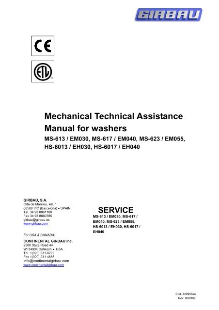
1<strong>Mechanical</strong> <strong>Technical</strong> <strong>Assistance</strong><strong>Manual</strong> <strong>for</strong> <strong>washers</strong>MS-613 / EM030, MS-617 / EM040, MS-623 / EM055,HS-6013 / EH030, HS-6017 / EH040GIRBAU, S.A.Crta de Manlleu, km. 108500 VIC (Barcelona) • SPAINTel. 34 93 8861100Fax 34 93 8860785girbau@girbau.eswww.girbau.comFor USA & CANADA:CONTINENTAL GIRBAU Inc.2500 State Road 44WI 54904 Oshkosh • USATel. 1(920) 231-8222Fax 1(920) 231-4666info@continentalgirbau.comwww.continentalgirbau.comSERVICEMS-613 / EM030, MS-617 /EM040, MS-623 / EM055,HS-6013 / EH030, HS-6017 /EH040Cod. 422907enRev. 00/0107
Bearing and Seal replacementMS-613 / EM030, MS-617 / EM040, MS-623 / EM055HS-6013 / EH030, HS-6017 / EH0401SAFETY INSTRUCTIONS11WARNING ¡INSPECTION ROUTINES, MAINTENANCE OR REPAIR• The actions described in these instructions are strictly reserved <strong>for</strong> Service Technicians whohave been authorized by the manufacturer. Any actions carried out by personnel who areunauthorized by the manufacturer will be considered to be improper and will result in theautomatic void of washer’s warranty.• The manufacturer will not accept responsibility <strong>for</strong> any physical and/or material damage causedby actions taken by unauthorized personnel.• Compliance with the safety warnings listed in the Installation <strong>Manual</strong> is obligatory; check thembe<strong>for</strong>e. Read them be<strong>for</strong>e servicing the washer.• Avoid carrying out any course of action on the machine without having first carefully read thewasher’s installation and operating manuals, paying special attention to the safety instructions.• Making inspections, maintenance or repairs without taking safety measures or having thenecessary technical competence can cause ELECTRICAL SHOCK OR SERIOUSACCIDENTS.• COMPLETELY disconnect the machine from the original power source and check <strong>for</strong> accidentalreconnection.• Disconnect the electrical connection from the external dosing to the washer. These circuits areindependent of the supply to the washer.• Moving the ON switch to the OFF position is not sufficient• Wait a minimum of (5) five minutes after disconnection to ensure the elimination of residualvoltage within the machine.• Close and mechanically interlock the water supply valves and check that machine hasCOMPLETELY drained, parts have cooled down and that no pieces are in movement throughinertiaINDEXSAFETY INSTRUCTIONS1. Preparation1.1. Required tools.1.2. Parts and materials.1.3. Parts.2. Disassembly2.1. Disassembling the covers2.2. Dismantling the bearing box.3. Bearing box3.1. Disassembling the bearings3.2. Changing the bearings3.3. Changing the seal ring.4. Assembling4.1 Assembling the bearings’ box4.2 Assembling the covers6. Final checking6.1. Checking the machine.Cod. 422907enRev. 00/0107
1. PREPARATIONBearing and Seal replacement22MS-613 / EM030, MS-617 / EM040, MS-623 / EM055HS-6013 / EH030, HS-6017 / EH04021.1. Required tools.DISASSEMBLYASSEMBLYRear coverTop coverDrum pulleyBearings’ boxBearingsSeals ringTORX 25 screwdriverKey supplied with the machine.TOOLS19mm (3/4 inch) wrench. For MS-613 / 617 HS-6013 units22mm (7/8 inch) wrench. For MS-623 / HS-6017 units.13mm tube wrench. 13mm (1/2 inch.) flat wrenchTwo wrench 17mm (11/16 inch.).Nylon-headed hammer (approx. recommended weight: 4kg)19mm (3/4 inch) wrench. For MS-613 / 617 HS-6013 units22mm (7/8 inch) wrench. For MS-623 / HS-6017.TOOLS DESCRIPTIONTOOLSMS-613 / 617EM030 / 040HS-6013 / EH030MS-623 / EM055HS-6017 / EH040CODECODEDrum centring device A 439711 439703Three legged extractor 1310 LT.BHydraulic Press 15T.C439729 43972922mm square-head wrenchDShaft box extensionEDrum fixing supportM 439695 439687Drum fixing cablePShaft protector G 439885 439877Rear bearing inserter H 437558 437459Front bearing inserter I 437566 437467Extractor <strong>for</strong> seal ring J 437616 437525Inserter <strong>for</strong> radial seal K 438432 437509Inserter <strong>for</strong> seal ring L 439745 439737Drum inserterN46mm. wrenchW439679 439661To identify the letters in the TOOLS section, refer to the positions as shown in the various photosthroughout the manual.Cod. 422907enRev. 00/0107
Bearing and Seal replacementMS-613 / EM030, MS-617 / EM040, MS-623 / EM055HS-6013 / EH030, HS-6017 / EH04031.2. Pieces and materialsFor identifying the pieces, consult their position in the figures in section 1.3.33DESCRIPTION POSITION QUANTITYToric gasket ∅68x∅76x4 12 2Seal ring 2 1Vring 85. 3 1Vring plate. 14 1Seal housing cover 22 1Toric gasket 6x12x3. 13 6Seal ∅85x∅110x12 BA. 19 1Bearing 6313 21 1Bearing 6310 20 1SHELL alvania 3 grease50 gr. (approx)SiliconeAny kind of non-acid sealing silicon can be used. It isimportant to use a fine opening applicator.1.3. Parts listNOTEThe numbers on the drawing above correspond to those from machines parts list HS-6017 / EH040,MS-613 / EM030, MS-617 / EM040 & MS-623 / EM055.The system <strong>for</strong> bearing replacement is the same regardless of any differences there may bebetween the different machine models HS / EH & MS / EM.Cod. 422907enRev. 00/0107
Bearing and Seal replacement44MS-613 / EM030, MS-617 / EM040, MS-623 / EM055HS-6013 / EH030, HS-6017 / EH04042. DISASSEMBLY2.1. Disassembling the covers.- Rear central cover. Take out the fasteningscrews, move the cover upwards andseparate it from the machine (fig. 1).- Top cover. Open the top cover using thetools supplied by the manufacturer andremove.fig.12.2. Dismantling the bearing box.- Open the machine door and fit centringdevice A to the drum aperture. (fig. 2).fig.2- Remove the overflow connecting hose.- Open the rear door to the power supplybox.- Dismantle the power supply box CA andput to one side to have more room tomanouevre ( only in MS-613, MS-617 andHS-6013 machines). (fig. 3).- Dismantle and slightly move away thedispenser CD to have more room tomanouevre. Remove the hose from thecollector.- Remove the belt from the drum pulley.- Remove the screw fastening the drumpulley. Remove the pulley from the shaft.- Note down the position of the level sensortube in order to put it back duringassembly.- Note down the position of the screws and<strong>washers</strong> in order to put them back duringassembly.- Take out the X nuts (fig.) fastening thebearings’ box to the back of the outer drum.- Take out the Y screws (fig. 4) fastening thebearings’ box to the outer drum.fig. 3fig. 4Cod. 422907enRev. 00/0107
Bearing and Seal replacement55MS-613 / EM030, MS-617 / EM040, MS-623 / EM055HS-6013 / EH030, HS-6017 / EH0405(It is advisable to have this operationper<strong>for</strong>med by two people)- Remember to lubricate the tool bolts toavoid any jamming.- Check that press bolt C is completelyunscrewed.- Place the protective cover on the shaft, fitthe hydraulic press C, fit extractor B andtighten all slightly using the 22m squareheadwrench D.- Screw together the hydraulic press C andthe extractor B until the box is releasedfrom the shaft. (fig. 5).fig. 5IMPORTANTThis operation must be carried out withextreme care to avoid the risk of knockingeither of the two bearings.- Once the box is released remove the tools,fit shaft extension E and remove thebearings box. (fig. 6).fig. 63. BEARINGS’ BOX3.1. Disassembling the bearings.- Place the bearing box in such a way thatthe Vring protection plate can be removed.- Remove the Vring protection plate usingthe fixed wrench. (fig. 7).fig. 7- Remember to lubricate the tool bolt toavoid any jamming.- Turn the box round so that bearings canmove.- Place the rear bearing extractor I on thebearing box and protect the extractor screwwith tool G.- Remove the set using extractor B and the22mm square-head wrench. (fig.8).fig.8Cod. 422907enRev. 00/0107
Bearing and Seal replacement66MS-613 / EM030, MS-617 / EM040, MS-623 / EM055HS-6013 / EH030, HS-6017 / EH04063.2. Changing the bearings.- Clean the bearings’ box, especially thearea housing the bearings, lightly lubricatethe bearing housing to make it easier tomount.- Lean the conical trunk end of the bearings’box on a hard, clean and flat surface.- Position the front bearing in its housing (thenumbered side of the bearing in theexternal part). Introduce it up to the end ofthe box using the H tool (fig. 9).fig. 9- Place the radial seal on the seal housingcover with the spring facing upwards andusing K tool make sure it is inserted as faras it will go. (fig. 10).fig. 10- Spread a little grease on the inside of theradial lip seal, just where the spring is.- Apply a fine thread of silicon on the sealhousing cover, skirting round the drilledholes <strong>for</strong> drainage and air vent. (fig. 11).fig. 11- Place the seal housing cover on the insideof the box, bearing in mind the position ofthe drainage hole and the air vent- Apply a fine thread of silicon to the cover asshown in the photograph.(fig.12).fig. 12Cod. 422907enRev. 00/0107
Bearing and Seal replacement77MS-613 / EM030, MS-617 / EM040, MS-623 / EM055HS-6013 / EH030, HS-6017 / EH0407- Put the Vring plate in position and place thetoric gaskets in the drill holes. (fig. 13).fig. 13- Place the Vring protection plate in positionand finish assembling the bearing boxusing the 6x25 bolts. (fig. 14).fig. 14- Using a fine object, clean off any excesssilicone from the drainage and air ventholes. (fig. 15).fig. 15- Turn the box and insert the cover <strong>for</strong> thebearings into the box with the conical endfacing outwards. (fig. 16).fig. 16Cod. 422907enRev. 00/0107
Bearing and Seal replacement88MS-613 / EM030, MS-617 / EM040, MS-623 / EM055HS-6013 / EH030, HS-6017 / EH0408- Position the rear bearing in its housing (thenumbered side of the bearing in theexternal part). Introduce it up to the end ofthe separator using I tool (fig. 17).- Check that the bearings’ end piece ispressed between the two bearings.fig. 173.3. Changing the seal ring- This procedure is carried out from behindthrough the space left by the central hole inthe outer drum.- Remove the Vring seal and remove the ringseals from the drum shaft using tool J. (fig.18).- Remove the toric gaskets from inside thering.fig. 18- Insert the two new toric gaskets inside theseal ring (fig.19).fig. 19- This procedure is carried out from behindthrough the space left by the central hole inthe outer drum.- Lubricate the shaft with soapy water tomake the assembly easier, insert the sealring into the shaft using tool L until it meetsflush with the drum star.(fig. 20).fig. 20Cod. 422907enRev. 00/0107
Bearing and Seal replacement99MS-613 / EM030, MS-617 / EM040, MS-623 / EM055HS-6013 / EH030, HS-6017 / EH0409- Insert the Vring with the lip facing upwardson the outside of the ring paying specialattention to the position of the lip. (fig. 21).4 Assembling4.1. Assembling the bearings’ box.fig. 21IMPORTANTThis operation must be carried out withextreme care to avoid the risk of knockingeither of the two bearings.(It is advisable to have this operationper<strong>for</strong>med by two people)- Fix extension E on to the shaft.- Position the bearing box in the drum shaftmaking sure to match up the fixing points.Remember the drainage hole is on thebottom part. (fig. 22.)fig. 22- Mount the fixing support M.- Fix cable P on the outer part of the shaftextension E.- Tighten cable P until the bearing box iscentred with the outer drum. (fig. 23).- Push the bearings box towards the insideuntil it fits into the central studs at thebottom of the outer drum.- Remove the support M, tightening cable Pand extension E.fig. 23- Remember to lubricate the tool bolt toavoid any jamming.- Fix inserter tool N keeping the bolt outsidefirmly locked with a 46mm wrench andtightening the inside nut with the other46mm wrench W until the bearing box is atthe bottom. (fig. 24).fig.24Cod. 422907enRev. 00/0107
- Fix the bearing box to the bottom of theouter drum using nuts X and thecorresponding <strong>washers</strong>.(fig. 25). Do nottighten.- Fasten the ends of the bearings’ box to theedge of the outer drum by means of the Yscrews and the corresponding nuts and<strong>washers</strong> (fig. 25).- Avoid letting the level sensor tube becomepressed by the bearings’ box.- Tighten the central fastening screws X firstand then the peripheral ones Y.1010MS-613 / EM030, MS-617 / EM040, MS-623 / EM055HS-6013 / EH030, HS-6017 / EH04010Bearing and Seal replacementfig. 25- Replace the power supply box CA. (fig. 26).- Close the rear door to the power supplybox.- Replace the dispenser CD and the hosefrom the collector.- Replace the overflow pipe.fig. 26- Remove the centring device A from thedrum opening.- Replace the pulley and tighten the fixingscrew.- Check the drum turns freely- Replace the belt. (fig. 27).fig. 274.2. Assembling the covers.- Rear central cover. Position the rear coverbeneath the rear panel and fix in place withthe screws. (fig. 28).- Top cover. Insert the cover into the two rearhinges and close with the keys supplied bythe manufacturer.fig.28Cod. 422907enRev. 00/0107
Bearing and Seal replacement1111MS-613 / EM030, MS-617 / EM040, MS-623 / EM055HS-6013 / EH030, HS-6017 / EH040115. FINAL CHECKING5.1. Checking the machine.Once ALL the washing machine covers are in place and fastened, check the operation and watertightness of the washing machine.WARNING!!NEVER START THE MACHINE BEFORE MOUNTING AND FASTENING ALL THEWASHING MACHINE COVERSProcedure:- Check that the drainpipe outlet is placed and fastened correctly.- Open the manual water supply valves.- Connect the power supply of the washing machine.- Load the washing machine with clothes.- Select a washing program. It is preferable to use a program with high temperature.- Run the selected program. During the execution of the washing cycle, check that no alarmsappear, which indicate a malfunction in the machine, especially those related with the inverter,motor.- Once finalized, disconnect the power supply and close the manual valves of the water inlets.- Take the front lower cover and the rear cover off.- Check that the base of the machine is dry and that no bath loss occurs, especially in the joints ofthe front panel of the outer drum and the door gasket.- Check that no bath loss occurs, especially in the joints of the bearings’ box and the back of theouter drum or through the drainage tube.- In the case of not observing any kind of anomaly, put the covers on.- Open the manual valves and connect the power supply.Remember that:- In LOGI Control machines, there is the possibility of accelerating up the program (see Instruction<strong>Manual</strong>, section 2.5).- In COIN machines, there is the possibility of using the DEMO program (see Advanced Instruction<strong>Manual</strong>, section 3.4).- In INTELI Control machines, there is the possibility of accelerating up the program (seeInstruction <strong>Manual</strong>, section 4.4).Cod. 422907enRev. 00/0107
![Sesión B - [24 x 80]](https://img.yumpu.com/50032046/1/184x260/sesian-b-24-x-80.jpg?quality=85)