Crosshole/Downhole Seismic - Olson Instruments, Inc.
Crosshole/Downhole Seismic - Olson Instruments, Inc.
Crosshole/Downhole Seismic - Olson Instruments, Inc.

You also want an ePaper? Increase the reach of your titles
YUMPU automatically turns print PDFs into web optimized ePapers that Google loves.
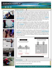
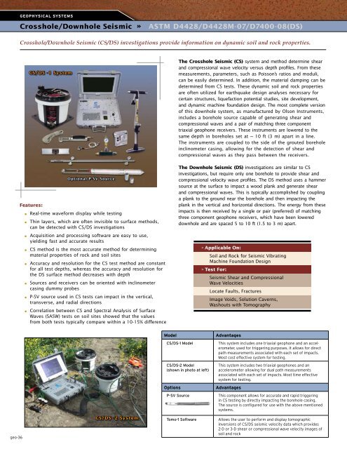
Geophysical Systems<strong>Crosshole</strong>/<strong>Downhole</strong> NDE 360 » One Platform <strong>Seismic</strong> - Multiple » ASTM NDE D4428/D4428M-07/D7400-08(DS)Tests<strong>Crosshole</strong>/<strong>Downhole</strong> <strong>Seismic</strong> (CS/DS) investigations provide information on dynamic soil and rock properties.CS/DS -1 SystemThe <strong>Crosshole</strong> <strong>Seismic</strong> (CS) system and method determine shearand compressional wave velocity versus depth profiles. From thesemeasurements, parameters, such as Poisson’s ratios and moduli,can be easily determined. In addition, the material damping can bedetermined from CS tests. These dynamic soil and rock propertiesare often utilized for earthquake design analyses necessary forcertain structures, liquefaction potential studies, site development,and dynamic machine foundation design. The most complete versionof this downhole system, as manufactured by <strong>Olson</strong> <strong>Instruments</strong>,includes a borehole source capable of generating shear andcompressional waves and a pair of matching three componenttriaxial geophone receivers. These instruments are lowered to thesame depth in boreholes set at ~ 10 ft (3 m) apart in a line.The instruments are coupled to the side of the grouted boreholeinclinometer casing, allowing for the detection of shear andcompressional waves as they pass between the receivers.Features:■■■■■■■■■■■■■■■■Optional P-SV SourceReal-time waveform display while testingThin layers, which are often invisible to surface methods,can be detected with CS/DS investigationsAcquisition and processing software are easy to use,yielding fast and accurate resultsCS method is the most accurate method for determiningmaterial properties of rock and soil sitesAccuracy and resolution for the CS test method are constantfor all test depths, whereas the accuracy and resolution forthe DS surface method decreases with depthSources and receivers can be oriented with inclinometercasing dummy probesP-SV source used in CS tests can impact in the vertical,transverse, and radial directionsCorrelation between CS and Spectral Analysis of SurfaceWaves (SASW) tests on soil sites showed that the valuesfrom both tests typically compare within a 10-15% differenceThe <strong>Downhole</strong> <strong>Seismic</strong> (DS) investigations are similar to CSinvestigations, but require only one borehole to provide shear andcompressional velocity wave profiles. The DS method uses a hammersource at the surface to impact a wood plank and generate shearand compressional waves. This is typically accomplished by couplinga plank to the ground near the borehole and then impacting theplank in the vertical and horizontal directions. The energy from theseimpacts is then received by a single or pair (preferred) of matchingthree component geophone receivers, which have been lowereddownhole and are spaced 5 to 10 ft (1.5 to 3 m) apart.» Applicable On:Soil and Rock for <strong>Seismic</strong> VibratingMachine Foundation Design» Test For:<strong>Seismic</strong> Shear and CompressionalWave VelocitiesLocate Faults, FracturesImage Voids, Solution Caverns,Washouts with TomographyModelAdvantagesCS/DS-1 ModelThis system includes one triaxial geophone and an accelerometer,used for triggering purposes. It allows for directpath measurements associated with each set of impacts.Most cost effective system for testing.CS/DS-2 Model(shown in photo at left)This system includes two triaxial geophones and anaccelerometer allowing for dual path measurementsassociated with each set of impacts. Most time effectivesystem for testing.OptionsAdvantagesP-SV SourceThis component allows for accurate and rapid triggeringin CS testing by directly impacting the borehole casing.The source is configured for use with the above mentionedsystems.geo-36CS/DS -2 SystemTomo-1 SoftwareAllows the user to perform and display tomographicinversions of CS/DS seismic velocity data which provides2-D or 3-D shear or compressional wave velocity images ofsoil and rock
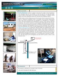
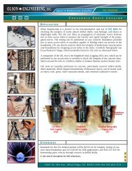
Geophysical Systems<strong>Crosshole</strong>/<strong>Downhole</strong> <strong>Seismic</strong> » ASTM D4428/D4428M-07/D7400-08(DS)MethodThe CS investigation requires drilling of two or more (ideallythree) boreholes cased with PVC or slope inclinometer casingfor deeper borings up to 328 ft (100 m), and grouted inaccordance with ASTM standards to ensure goodtransmission of wave energy. The boreholes are typically 4-6inches in diameter cased with 2.32 to 3 inch (59 to 76 mm)I.D. casing, not to exceed 4 inches (102 mm) I.D. The testingis simplified if inclinometer casing is used rather than normalPVC pipe. Typical distances between adjacent in-lineboreholes are on the order of 10 ft (3 m). The testing isperformed by lowering both the source and receiver(s) to aninvestigation depth, firing the source, and recording theenergy with the receivers.The DS investigation requires drilling a single boreholewith similar specifications as listed above, except that onlya single grouted 2 inch (50 mm) to 3 inch (76 mm) I.D. PVCcasing is needed, not to exceed 4 inches (102 mmm) I.D.The testing is performed by lowering the receiver(s) to aninvestigation depth, impacting the coupled surface plank,and recording the energy with the receivers.All of the CS/DS Modelsare compatible with <strong>Olson</strong>Instrument’s P-SV Source.This component providesthe user with the mostaccurate and rapid methodof generating impacts.DummyProbeOptionalP-SV Source Receiver 1Triple PortManifoldSVPDummyProbesSVOptionalReceiver 2PTriaxialGeophoneReceiversData CollectionThe user friendly CS/DS software is written and tested at <strong>Olson</strong><strong>Instruments</strong>’ corporate office in Colorado. We do not outsourceany tech support questions and, should you require softwaresupport, we welcome your questions and comments.Data Example » 1Available ModelsThe <strong>Crosshole</strong>/<strong>Downhole</strong> <strong>Seismic</strong> system is available intwo different models with an optional P-SV Source. Allsystems require the <strong>Olson</strong> <strong>Instruments</strong> Freedom Data PCplatform for testing:1. <strong>Crosshole</strong>/<strong>Downhole</strong> <strong>Seismic</strong> - 1 (CS/DS-1)2. <strong>Crosshole</strong>/<strong>Downhole</strong> <strong>Seismic</strong> - 2 (CS/DS-2)The CS/DS -1 Model is the base model for <strong>Crosshole</strong>or <strong>Downhole</strong> <strong>Seismic</strong> testing. This system includes onetriaxial geophone and one accelerometer allowing fordirect path measurements associated with each set ofimpacts, either in the borehole if a downhole source isused (CS) or on the surface if a downhole source is notused (DS). Specifically, this system can be used to test thematerial between the impact and the receiver’s location inthe borehole.The CS/DS -2 Model includes two geophones and anaccelerometer allowing for dual path measurementsassociated with each set of impacts, either in the boreholeor on the surface. Specifically, this system can be used totest the material between the impact and the receivers’location in the borehole(s). This DS-2 system performs theFreedom Data PC Required,Sold SeparatelyScreen shot from an <strong>Olson</strong> <strong>Instruments</strong> Freedom Data PC showing awaveform recorded during a <strong>Crosshole</strong> <strong>Seismic</strong> test.geo-37