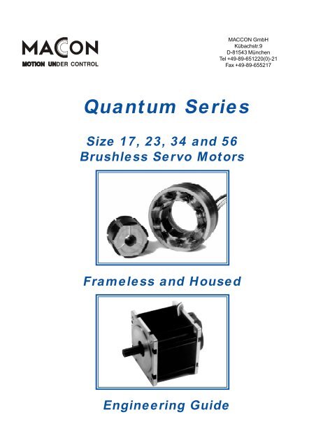
Quantum Series - MACCON GmbH
Quantum Series - MACCON GmbH
Quantum Series - MACCON GmbH
You also want an ePaper? Increase the reach of your titles
YUMPU automatically turns print PDFs into web optimized ePapers that Google loves.
Electrical and Mechanical DataSize ConstantsMechanical Constants<strong>Quantum</strong> <strong>Series</strong>Size 17SYMBOL UNIT QB01700 QB01701 QB01702 QB01703Max Cont. Stall Torque T CNm 0.08 0.15 0.23 0.30Max Rated Torque, 25% T RNm 0.65 1.19 1.87 2.41Motor Constant, K MNm/√W 0.023 0.035 0.048 0.057Electrical Time Constant T Emsec 0.38 0.52 0.59 0.65Mechanical Time Constant T Mmsec 2.03 1.67 1.33 1.26Thermal Resistance TPR °C/Watt 4.7 3.29 2.58 2.14Viscous Damping F iNm/rpm 5.3E-7 1.1E-6 1.6E-6 2.2E-6Max Cogging Torque T FNm 7E-3 1.1E-2 1.3E-2 1.6E-2Frameless Motor Inertia J MKg.m 2 1.0E-7 2.0E-6 3.1E-6 4.1E-6Frameless Motor Weight Wt Kg 0.07 0.14 0.21 0.27Housed Motor Inertia J MKg.m 2 1.1E-6 2.1E-6 3.1E-6 4.2E-6Housed Motor Weight Wt Kg 0.22 0.34 0.47 0.58Number of Poles - - 6 6 6 6Winding Constants A B C A B C A B C A B CDesign Voltage V PVolts 24 40 130 24 40 130 24 40 130 24 40 130Peak Torque T PNm 0.65 0.65 0.65 1.15 1.19 1.19 1.55 1.87 1.87 1.82 2.41 2.41Peak Current I PAmperes 36 24 15 44 35 14 42 41 16 42 49 20Torque Constant,±10% K TNm/A 0.018 0.027 0.043 0.026 0.034 0.080 0.036 0.045 0.114 0.043 0.049 0.119No Load Speed S NLRPM 12775 14068 29095 8874 11287 15488 6318 8555 10851 5302 7855 10444Rad/s 1337 1473 3046 829 1182 1621 661 895 1136 555 822 1093BEMF Constant, ±10% K BV/KRPM 1.88 2.84 4.46 2.70 3.54 8.39 3.79 4.67 11.98 4.52 5.09 12.44V/rad/s 0.018 0.027 0.043 0.026 0.034 0.080 0.036 0.045 0.114 0.043 0.049 0.119Terminal Resistance, ±12% R MOhms 0.63 1.51 3.76 0.53 1.08 6.44 0.56 0.86 5.62 0.56 0.72 4.43Terminal Inductance, ±30% L MmH 0.24 0.55 1.36 0.28 0.48 2.69 0.33 0.50 3.29 0.37 0.47 2.81Speed/Torque CurvesSpeed RPMTorque Nm0 0.05 0.1 0.15 0.2 0.25 0.32000016000120008000QB01703QB017024000QB01701QB0170000 5 10 15 20 25 30 35 40 45Torque oz. in.2000160012008004000Speed rad/secContinuous Duty Speed/Torque Curves for100°C Temperature rise.The continuous duty speed/torque curves provide a guide to theoperational capability of the motors. Continuous operation at aloadpoint on or under the curve limits the temperature rise of themotor to 100°C. Although the duration of acceleration or decelerationperiods should be checked, the RMS speed and torque combinationshould also lie on or under the continuous duty curve. The curvesassume housed motors mounted to a nominal size of aluminumheatsink in a 25°C ambient environment and still air cooling. Higherambient temperatures will generally decrease the continuous dutycapability of a motor. With increased heatsink areas or improvedcooling such as forced air or water, the continuous duty capability ofthe motor may be increased. However, for most applications, thepractical maximum motor temperature is 150°C with Hall effect<strong>MACCON</strong> <strong>GmbH</strong> Kübachstr.9 D-81543 München Tel +49-89-651220(0)-21 Fax +49-89-6552175
Electrical and Mechanical DataSize ConstantsMechanical Constants<strong>Quantum</strong> <strong>Series</strong>Size 23SYMBOL UNIT QB02300 QB02301 QB02302 QB02303Max Cont. Stall Torque T CNm 0.36 0.68 0.98 1.28Max Rated Torque, 25% T RNm 3.94 7.9 11.8 15.6Motor Constant, K MNm/√W 0.076 0.121 0.155 0.181Electrical Time Constant T Emsec 0.94 1.14 1.22 1.25Mechanical Time Constant T Mmsec 1.30 1.03 0.94 0.92Thermal Resistance TPR °C/Watt 2.79 2.00 1.59 1.26Viscous Damping F iNm/rpm 2.5E-6 5.3E-6 7.9E-6 1.1E-5Max Cogging Torque T FNm 0.018 0.029 0.036 0.044Frameless Motor Inertia J MKg.m 2 7.6E-6 1.5E-5 2.3E-5 3.0E-5Frameless Motor Weight Wt Kg 0.25 0.48 0.71 0.95Housed Motor Inertia J MKg.m 2 7.9E-6 1.5E-5 2.3E-5 3.0E-5Housed Motor Weight Wt Kg 0.68 0.92 1.17 1.42Number of Poles - - 6 6 6 6Winding Constants A B C A B C A B C A B CDesign Voltage V PVolts 24 40 130 24 40 130 24 40 130 24 40 130Peak Torque T PNm 3.64 3.94 3.94 4.65 6.00 7.81 7.63 9.86 11.72 7.82 10.34 15.62Peak Current I PAmperes 95 81 32 61 62 40 100 104 56 77 81 70Torque Constant,±10% K TNm/A 0.038 0.048 0.121 0.076 0.096 0.192 0.076 0.095 0.208 0.101 0.126 0.222No Load Speed S NLRPM 5994 7888 10254 3014 3981 6470 3014 4035 5860 2269 3026 5588Rad/s 627 826 1073 315 416 677 315 422 624 237 316 585BEMF Constant, ±10% K BV/KRPM 4.0 5.0 12.6 7.9 10.0 20.0 7.9 9.9 21.8 10.5 13.2 23.2V/rad/s 0.038 0.048 0.121 0.076 0.096 0.192 0.076 0.095 0.208 0.101 0.126 0.222Terminal Resistance, ±12% R MOhms 0.25 0.40 2.53 0.39 0.63 2.55 0.24 0.38 2.00 0.31 0.48 1.61Terminal Inductance, ±30% L MmH 0.23 0.38 2.37 0.45 0.72 2.88 0.29 0.46 2.22 0.39 0.60 1.87Speed/Torque CurvesSpeed RPMTorque Nm0 0.2 0.4 0.6 0.8 1 1.2 1.4120001200100001000800080060006004000QB02303400QB023022000QB02301200QB02300000 20 40 60 80 100 120 140 160 180 200Torque oz. in.Speed rad/secContinuous Duty Speed/Torque Curves for100°C Temperature rise.The continuous duty speed/torque curves provide a guide to theoperational capability of the motors. Continuous operation at aloadpoint on or under the curve limits the temperature rise of themotor to 100°C. Although the duration of acceleration or decelerationperiods should be checked, the RMS speed and torque combinationshould also lie on or under the continuous duty curve. The curvesassume housed motors mounted to a nominal size of aluminumheatsink in a 25°C ambient environment and still air cooling. Higherambient temperatures will generally decrease the continuous dutycapability of a motor. With increased heatsink areas or improvedcooling such as forced air or water, the continuous duty capability ofthe motor may be increased. However, for most applications, thepractical maximum motor temperature is 150°C with Hall effect<strong>MACCON</strong> <strong>GmbH</strong> Kübachstr.9 D-81543 München Tel +49-89-651220(0)-21 Fax +49-89-6552177
<strong>Quantum</strong> <strong>Series</strong>Size 34Frameless MotorHoused Motor<strong>MACCON</strong> <strong>GmbH</strong> Kübachstr.9 D-81543 München Tel +49-89-651220(0)-21 Fax +49-89-6552178
Electrical and Mechanical Data<strong>Quantum</strong> <strong>Series</strong>Size 34Size ConstantsSYMBOL UNIT QB03400 QB03401 QB03402 QB03403Max Cont. Stall Torque T CNm 0.81 1.57 2.32 3.03Max Rated Torque, 25% T RNm 5.38 10.8 16.2 20.9Motor Constant, K MNm/√W 0.142 0.245 0.316 0.369Electrical Time Constant T Emsec 1.89 2.57 2.78 2.37Mechanical Time Constant T Mmsec 2.59 1.74 1.57 1.53Thermal Resistance TPR °C/Watt 1.87 1.51 1.15 0.92Viscous Damping F iNm/rpm 5.1E-6 1.0E-5 1.6E-5 2.2E-5Max Cogging Torque T FNm 0.025 0.035 0.046 0.056Mechanical ConstantsFrameless Motor Inertia J MKg.m 2 5.2E-5 1.0E-4 1.5E-4 2.1E-4Frameless Motor Weight Wt Kg 0.60 1.17 1.73 2.29Housed Motor Inertia J MKg.m 2 5.3E-5 1.0E-4 1.5E-4 2.1E-4Housed Motor Weight Wt Kg 1.55 2.24 2.92 3.6Number of Poles - - 6 6 6 6Winding Constants A B C A B C A B C A B CDesign Voltage V PVolts 24 40 130 24 40 130 24 40 130 24 40 130Peak Torque T PNm 5.00 5.38 5.38 10.8 10.8 10.8 14.7 16.2 16.2 17.7 21.1 20.9Peak Current I PAmperes 51 49 34 81 65 40 91 81 51 96 100 74Torque Constant,±10% K TNm/A 0.098 0.109 0.154 0.133 0.166 0.266 0.162 0.200 0.318 0.184 0.208 0.280No Load Speed S NLRPM 2367 3499 8037 1722 2286 4665 1413 1913 3802 1244 1835 4430Rad/s 247 366 841 180 240 488 148 200 408 130 192 464BEMF Constant, ±10% K BV/KRPM 10.1 11.4 16.1 13.9 17.4 27.8 16.9 20.9 33.3 19.2 21.7 29.3V/rad/s 0.097 0.109 0.154 0.133 0.166 0.266 0.162 0.200 0.318 0.184 0.208 0.280Terminal Resistance, ±12% R MOhms 0.46 0.58 1.17 0.29 0.46 1.24 0.26 0.40 1.03 0.24 0.31 0.56Terminal Inductance, ±30% L MmH 0.88 1.11 2.24 0.75 1.18 3.03 0.73 1.11 2.82 0.59 0.75 1.36Speed/Torque CurvesTorque NmSpeed RPM0 0.5 1 1.5 2 2.5 3120001000080006000120010008006004000QB03403400QB034022000QB03401200QB03400000 50 100 150 200 250 300 350 400 450Torque oz. in.Speed rad/secContinuous Duty Speed/Torque Curves for100°C Temperature rise.The continuous duty speed/torque curves provide a guide to theoperational capability of the motors. Continuous operation at aloadpoint on or under the curve limits the temperature rise of themotor to 100°C. Although the duration of acceleration or decelerationperiods should be checked, the RMS speed and torque combinationshould also lie on or under the continuous duty curve. The curvesassume housed motors mounted to a nominal size of aluminumheatsink in a 25°C ambient environment and still air cooling. Higherambient temperatures will generally decrease the continuous dutycapability of a motor. With increased heatsink areas or improvedcooling such as forced air or water, the continuous duty capability ofthe motor may be increased. However, for most applications, thepractical maximum motor temperature is 150°C with Hall effect<strong>MACCON</strong> <strong>GmbH</strong> Kübachstr.9 D-81543 München Tel +49-89-651220(0)-21 Fax +49-89-6552179
<strong>Quantum</strong> <strong>Series</strong>Size 56Frameless MotorHoused MotorFinal definition of the housed versions of the QB05600 <strong>Series</strong> motorshad not been completed at the time of printing.Please contact our sales group for the latest information.<strong>MACCON</strong> <strong>GmbH</strong> Kübachstr.9 D-81543 München Tel +49-89-651220(0)-21 Fax +49-89-65521710
Electrical and Mechanical DataSize ConstantsMechanical Constants<strong>Quantum</strong> <strong>Series</strong>Size 56SYMBOL UNIT QB05600 QB05601 QB05602 QB05603Max Cont. Stall Torque T CNm 4.29 8.03 11.10 14.10Max Rated Torque, 25% T RNm 30.3 57.2 85.1 113.5Motor Constant, K MNm/√W 0.56 0.88 1.09 1.29Electrical Time Constant T Emsec 5.09 5.49 6.59 6.83Mechanical Time Constant T Mmsec 1.13 0.93 0.92 0.88Thermal Resistance TPR °C/Watt 1.09 0.75 1.15 0.52Viscous Damping F iNm/rpm 2.3E-5 4.9E-5 7.5E-5 1.0E-4Max Cogging Torque T FNm 0.078 0.134 0.191 0.247Frameless Motor Inertia J MKg.m 2 3.6E-4 7.3E-4 1.1E-3 1.5E-3Frameless Motor Weight Wt Kg 1.72 3.99 5.84 7.76Housed Motor Inertia J MKg.m 2 6.3E-4 1.1E-3 1.6E-3 2.1E-3Housed Motor Weight Wt Kg 4.80 7.84 10.4 13.0Number of Poles - - 8 8 8 8Winding Constants A B C A B C A B C A B CDesign Voltage V PVolts 40 130 300 40 130 300 40 130 300 40 130 300Peak Torque T PNm 30.3 30.3 30.3 59.2 59.2 59.2 85.1 85.1 85.1 113.5 113.5 113.5Peak Current I PAmperes 224 121 62 409 204 93 498 263 124 640 299 154Torque Constant,±10% K TNm/A 0.135 0.250 0.486 0.145 0.290 0.633 0.171 0.323 0.683 0.177 0.380 0.734No Load Speed S NLRPM 2830 4971 5896 2634 4281 4528 2235 3847 4192 2156 3270 3903Rad/s 296 520 617 275 448 474 234 402 439 225 342 408BEMF Constant, ±10% K BV/KRPM 14.3 26.1 50.8 15.1 30.3 66.2 17.8 33.8 71.5 18.5 39.7 76.8V/rad/s 0.135 0.250 0.486 0.145 0.290 0.633 0.171 0.323 0.683 0.177 0.380 0.734Terminal Resistance, ±12% R MOhms 0.056 0.196 0.761 0.027 0.107 0.511 0.024 0.085 0.400 0.019 0.088 0.324Terminal Inductance, ±30% L MmH 0.287 0.981 3.715 0.146 0.586 2.788 0.160 0.570 2.556 0.127 0.585 2.187Speed/Torque CurvesSpeed RPMTorque Nm0 2 4 6 8 10 12 14 16800060004000QB056032000QB05602QB05601QB0560000 2 4 6 8 10 12Torque ft.lb.8006004002000Speed rad/secContinuous Duty Speed/Torque Curves for100°C Temperature rise.The continuous duty speed/torque curves provide a guide to theoperational capability of the motors. Continuous operation at aloadpoint on or under the curve limits the temperature rise of themotor to 100°C. Although the duration of acceleration or decelerationperiods should be checked, the RMS speed and torque combinationshould also lie on or under the continuous duty curve. The curvesassume housed motors mounted to a nominal size of aluminumheatsink in a 25°C ambient environment and still air cooling. Higherambient temperatures will generally decrease the continuous dutycapability of a motor. With increased heatsink areas or improvedcooling such as forced air or water, the continuous duty capability ofthe motor may be increased. However, for most applications, thepractical maximum motor temperature is 150°C with Hall effect<strong>MACCON</strong> <strong>GmbH</strong> Kübachstr.9 D-81543 München Tel +49-89-651220(0)-21 Fax +49-89-65521711
QB <strong>Series</strong>QS High EfficiencyQS01700Speed RPMTorque Nm0 0.05 0.1 0.15 0.2 0.25 0.330000250002000015000QS0170310000QS01702QS017015000QS0170000 5 10 15 20 25 30 35 40 45QS02300Torque oz. in.Torque Nm0 0.2 0.4 0.6 0.8 1 1.2 1.4200003000250020001500100050002000Speed rad/secQS High Efficiency MotorsThe QS versions of the <strong>Quantum</strong> <strong>Series</strong> of motors, are designedfor increased operating efficiency at higher speeds. This isaccomplished by the use of thinner, low core loss, laminationmaterial. The result is that for a given temperature rise, the motorcan operate at higher speed while still producing useful amounts ofoutput torque compared to the standard <strong>Quantum</strong> <strong>Series</strong> motors(QB) that are optimized for servo perfomance at lower operatingspeeds.The mechanical dimensions of the QS motors remain the same asthe QB versions. Except for the Viscous Damping and HysteresisDrag torque, the datasheet parameters for Size and Windingconstants remain the same.For loadpoints beyond those shown on the accompanying graphs,we can further optimize the magnetic circuit designs throughgeometry and material changes.Additionally, windings which are optimized for a specific160001600Speed RPM1200080004000QS02301QS02302QS023031200800400Speed rad/secQS02300000 20 40 60 80 100 120 140 160 180 200QS03400Torque oz. in.QS05600Torque Nm0 0.5 1 1.5 2 2.5 3180001800Torque Nm0 2 4 6 8 10 12 14 16120001200150001500100001000Speed RPM12000900060003000QS03401QS03400000 50 100 150 200 250 300 350 400 450Torque oz. in.QS03403QS034021200900600300Speed rad/secSpeed RPM800060004000QS05603QS056022000QS05601QS0560000 2 4 6 8 10 12Torque ft.lb8006004002000Speed rad/sec<strong>MACCON</strong> <strong>GmbH</strong> Kübachstr.9 D-81543 München Tel +49-89-651220(0)-21 Fax +49-89-65521712
QB <strong>Series</strong>Bearing Life CurvesQB/QS01700300.250 inch ID bearing, 20,000 hour life5 Lb Axial2510 Lb AxialRadial Load (Lbs)201510515 Lb Axial20 Lb AxialCalculations for life rating of 20,000 hours is basedupon combined radial and axial loads.Radial load applied 0.50 inches (12.7mm) frommounting face.10 lb (44N) maximum axial preload.8 mm ID bearing available.00 2500 5000 7500 10000 12500Speed (RPM)QB/QS02300Radial Load (Lbs)0.375 inch ID bearing, 20,000 hour life60504030201000 2500 5000 7500 10000 12500Speed (RPM)10 Lb Axial15 Lb Axial20 Lb Axial25 Lb AxialCalculations for life rating of 20,000 hours is basedupon combined radial and axial loads.Radial load applied 0.50 inches (12.7mm) frommounting face.15 lb (66N) maximum axial preload.0.5 inch ID bearing available.0.250 inch shaft option utilizes 0.375 inch IDbearingsQB/QS034000.500 inch ID bearing, 20,000 Hour Life6010 Lb AxialRadial Load (Lbs)504030201020 Lb Axial30 Lb Axial40 Lb AxialCalculations for life rating of 20,000 hours is basedupon combined radial and axial loads.Radial load applied 0.75 inches (19mm) frommounting face.20 lb (88N) maximum axial preload.0.375 inch shaft utilizes 0.500 inch ID bearing0.625 inch ID bearing available.00 2500 5000 7500 10000 12500Speed (RPM)<strong>MACCON</strong> <strong>GmbH</strong> Kübachstr.9 D-81543 München Tel +49-89-651220(0)-21 Fax +49-89-65521713
QB <strong>Series</strong>EncodersQB/QS01700 <strong>Series</strong>QB/QS02300 <strong>Series</strong><strong>MACCON</strong> <strong>GmbH</strong> Kübachstr.9 D-81543 München Tel +49-89-651220(0)-21 Fax +49-89-65521714
QB <strong>Series</strong>EncodersQB/QS03400 <strong>Series</strong>Encoder Connections<strong>MACCON</strong> <strong>GmbH</strong> Kübachstr.9 D-81543 München Tel +49-89-651220(0)-21 Fax +49-89-65521715
QB <strong>Series</strong>Rugged HousingsQB/QS01700 <strong>Series</strong>QB/QS01700 <strong>Series</strong><strong>MACCON</strong> <strong>GmbH</strong> Kübachstr.9 D-81543 München Tel +49-89-651220(0)-21 Fax +49-89-65521716
QB <strong>Series</strong>Rugged HousingsQB/QS02300 <strong>Series</strong>QB/QS02300 <strong>Series</strong><strong>MACCON</strong> <strong>GmbH</strong> Kübachstr.9 D-81543 München Tel +49-89-651220(0)-21 Fax +49-89-65521717
QB <strong>Series</strong>Rugged HousingsQB/QS03400 <strong>Series</strong>QB/QS03400 <strong>Series</strong><strong>MACCON</strong> <strong>GmbH</strong> Kübachstr.9 D-81543 München Tel +49-89-651220(0)-21 Fax +49-89-65521718
QB <strong>Series</strong>Mating ConnectorsQB/QS01700 <strong>Series</strong>QB/QS02300/3400 <strong>Series</strong><strong>MACCON</strong> <strong>GmbH</strong> Kübachstr.9 D-81543 München Tel +49-89-651220(0)-21 Fax +49-89-65521719
QB <strong>Series</strong>Brakes & ResolversHolding Brake OptionsResolver Options<strong>MACCON</strong> <strong>GmbH</strong> Kübachstr.9 D-81543 München Tel +49-89-651220(0)-21 Fax +49-89-65521720
QB <strong>Series</strong>Page reserved for future use.<strong>MACCON</strong> <strong>GmbH</strong> Kübachstr.9 D-81543 München Tel +49-89-651220(0)-21 Fax +49-89-65521721
QB <strong>Series</strong>GlossarySize ConstantsThese parameters are dependent upon the size andshape of the motor but are largely independent of thewinding used. However, special designs incorporatingdifferent lamination and magnet materials as well asdesign modifications such as increased magnetic airgaps can change these parameters. In such instances,a specific set of design data will be provided.Maximum Continuous Stall Torque (T C) is the amountof torque produced at zero speed which results in a100°C rise in temperature. Generally, the highestoperating temperature that should be allowed is 150°Cand is a combination of the ambient temperature andthe temperature rise for a given operating condition.Maximum Rated Torque (T R) is the amount of torquethat the motor can produce without danger of demagnetizingthe rotor. This torque is only available for shortdurations. Also, it may not be possible to produce theMaximum Rated Torque because of limitations ofvoltage and current (see Peak Torque).Motor Constant (K M) is the ratio of the peak torque tothe square root of the input power at stall with 25°Cambient temperature. This ratio is useful during the initialselection of a motor because it indicates the ability ofthe motor to convert electrical power into torque.K M= T P(Peak Torque)/√P P(Peak Input Power)orK M= K T(Torque Constant)/ √R M(Terminal Resistance)Electrical Time Constant (t F) is the ratio of inductanceL Min Henries, to the resistance R Min Ohms. This is theinductance and resistance as measured across any twophases in a delta or wye configuration.T E= L M/R MMechanical Time Constant (t M) is the time required toreach 63.2% of the motors maximum speed after theapplication of constant DC voltage through the commutationelectronics, ignoring friction, windage, and core losses.T M= J M* R M/ K T*K BThermal Resistance (TPR) correlates winding temperaturerise to the average power dissipated in thestator winding. The published TPR assumes that ahoused motor is mounted to an aluminum heatsink ofspecific dimensions. Additional cooling from forced air,water jacketing, or increased heatsinking decreases themotor Thermal Resistance allowing higher power outputsthan the published data.Heatsink Sizes:QB01700 <strong>Series</strong> 6 x 6 x 0.25 inches (152x152x6.3 mm)QB02300 <strong>Series</strong> 8 x 8 x 0.25 inches (203x203x6.3 mm)QB03400 <strong>Series</strong> 10x10x0.25 inches (254x254x6.3 mm)QB05600 <strong>Series</strong> 12x12x0.50 inches (305x305x12.7mm)Viscous Damping (F 0) gives an indication of the torquelost due to B.E.M.F. in the motor when the sourceimpedance is zero. F 0value can be represented asF 0= K T* K B/ R MMaximum Cogging Torque (T F) is principally the staticfriction torque felt as the motor is rotated at low speed.The published value does not include the bearingfriction of a housed motor.Mechanical DataRotor inertia (J M) is the moment of inertia of the rotorabout its axis of rotation.Motor Weight (W M) is the weight of the standard motor.Number of Poles (N P) is the number of permanentmagnet poles of the rotor. For the QB <strong>Series</strong> this isgenerally a total of six (three north and three south).Winding ConstantsThe winding constants are the parameters that varywith the number of wire turns per coil and the wire size.These parameters are collected under a alphabeticalwinding designation. A single frame size and length ofmotor will have several different windings. Specialwindings receive new designations in the sequence bywhich they are designed and released to production.Design Voltage (V P) is the nominal voltage required toproduce the peak torque when the rotor speed is zero andthe winding temperature is 25°C. As such, V Pis theproduct of I Pand R M. At any temperature greater than25°C, the required voltage to produce peak torque increasesdue to the increase in winding resistance. The<strong>MACCON</strong> <strong>GmbH</strong> Kübachstr.9 D-81543 München Tel +49-89-651220(0)-21 Fax +49-89-65521722
QB <strong>Series</strong>Connectionsdesign voltage is not a limit but a reference point for thedata.Peak Torque (T P) is the nominal value of developedtorque with the rated current I Papplied to the windings.For each winding specified the product of peak current( I P) and nominal torque sensitivity (K T) gives T Punlessthe maximum rated torque (T R) is reached.Motor Connections andCommutation LogicPeak Current (I P) is the rated current used to obtain thenominal peak torque from the motor with nominal torquesensitivity (K T). I Pis generally the design voltage dividedby the terminal resistance (R M).Torque Sensitivity (K T) is the ratio of the developedtorque to the applied current for a specific winding. K Tisrelated to the BEMF Constant K B.No Load Speed (S NL) is the theoretical no load speed ofthe motor with the design voltage applied.BEMF Constant (K B) is the ratio of voltage generated inthe winding to the speed of the rotor. K Bis proportional toK T.Terminal Resistance (R M) is the winding resistancemeasured between any two leads of the winding ineither a delta or wye configuration at 25°C.Terminal Inductance (L M) is the winding inductancemeasured between any two leads of the winding ineither delta or wye configuration at 25°C.Configuration DrawingsThe drawings reflect the standard configurations for boththe housed and frameless motors. Encoder and housingoptions are also detailed but customers may specifymechanical modifications such as shaft diameters andlengths as well as special mounting and cablingrequirements.Frameless motors are supplied with single stack rotorhubs for customer stacking to required rotor length. TheHall effects are integral to the stator assembly.<strong>MACCON</strong> <strong>GmbH</strong> Kübachstr.9 D-81543 München Tel +49-89-651220(0)-21 Fax +49-89-65521723
<strong>Quantum</strong> <strong>Series</strong>Brushless DC Motors<strong>MACCON</strong> <strong>GmbH</strong>Kübachstr.9D-81543 MünchenTel +49-89-651220(0)-21Fax +49-89-655217


