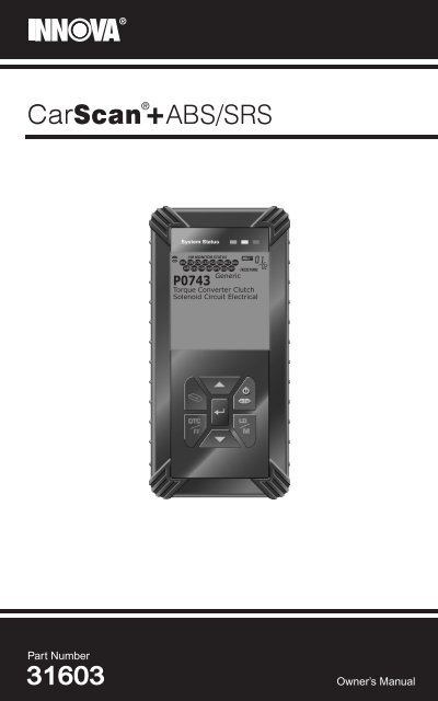
31603 - Innova Pro
31603 - Innova Pro
31603 - Innova Pro

Create successful ePaper yourself
Turn your PDF publications into a flip-book with our unique Google optimized e-Paper software.
Table of ContentsINTRODUCTIONWHAT IS OBD? ............................................................................. 1YOU CAN DO IT! .................................................................................... 2SAFETY PRECAUTIONSSAFETY FIRST! ............................................................................. 3ABOUT THE SCAN TOOLVEHICLES COVERED .................................................................. 5BATTERY REPLACEMENT .......................................................... 6SCAN TOOL CONTROLSCONTROLS AND INDICATORS ................................................... 7DISPLAY FUNCTIONS .................................................................. 8ONBOARD DIAGNOSTICSCOMPUTER ENGINE CONTROLS ............................................... 11DIAGNOSTIC TROUBLE CODES (DTCs) ..................................... 16OBD2 MONITORS ......................................................................... 19PREPARATION FOR TESTINGPRELIMINARY VEHICLE DIAGNOSTIC WORKSHEET................ 28BEFORE YOU BEGIN ................................................................... 31VEHICLE SERVICE MANUALS .................................................... 32USING THE SCAN TOOLCODE RETRIEVAL PROCEDURE ................................................ 33THE ENHANCED MAIN MENU ..................................................... 39VIEWING ENHANCED DTCs ........................................................ 40VIEWING ABS DTCs ...................................................................... 48VIEWING SRS DTCs ..................................................................... 51ERASING DIAGNOSTIC TROUBLE CODES (DTCs) .................... 53I/M READINESS TESTING ............................................................ 55ABOUT REPAIRSOLUTIONS® ..................................................... 60LIVE DATA MODEVIEWING LIVE DATA .................................................................... 62CUSTOMIZING LIVE DATA (PIDs) ............................................... 63RECORDING (CAPTURING) LIVE DATA ..................................... 64LIVE DATA PLAYBACK.................................................................. 68ADDITIONAL TESTSSPECIAL TEST MENU .................................................................. 70VIEWING VEHICLE INFORMATION ............................................. 74ADJUSTMENTS AND SETTINGS ................................................. 76GENERIC (GLOBAL) OBD2 PID LIST .................................................. 81VEHICLE APPLICATIONS - MAKES COVERED (ABS)DOMESTIC MAKES ...................................................................... 86ASIAN MAKES (OPTIONAL UPGRADE) ...................................... 86EUROPEAN MAKES (OPTIONAL UPGRADE) ............................. 86VEHICLE APPLICATIONS - MAKES COVERED (SRS)DOMESTIC MAKES ...................................................................... 87ASIAN MAKES (OPTIONAL UPGRADE) ...................................... 87EUROPEAN MAKES (OPTIONAL UPGRADE) ............................. 87GLOSSARYGLOSSARY OF TERMS AND ABBREVIATIONS .......................... 88WARRANTY AND SERVICINGLIMITED ONE YEAR WARRANTY ................................................ 93SERVICE PROCEDURES ............................................................. 93iCarScan+ ABS/SRS
IntroductionWHAT IS OBD?WHAT IS OBD?The Scan Tool is designed to work on all OBD2 compliant vehicles.All 1996 and newer vehicles (cars, light trucks and SUVs) sold inthe United States are OBD2 compliant.One of the most exciting improvements in theautomobile industry was the addition of onboarddiagnostics (OBD) on vehicles, or in morebasic terms, the computer that activates thevehicle’s “CHECK ENGINE” light. OBD1 wasdesigned to monitor manufacturer-specificsystems on vehicles built from 1981 to 1995.Then came the development of OBD2, which ison all 1996 cars and light trucks sold in the U.S. Like its predecessor,OBD2 was adopted as part of a government mandate to lower vehicleemissions. But what makes OBD2 unique is its universal application forall late model cars and trucks - domestic and import. This sophisticatedprogram in the vehicle’s main computer system is designed to detectfailures in a range of systems, and can be accessed through a universalOBD2 port, which is usually found under the dashboard. For all OBDsystems, if a problem is found, the computer turns on the “CHECKENGINE” light to warn the driver, and sets a Diagnostic Trouble Code(DTC) to identify where the problem occurred. A special diagnostic tool,such as the Scan Tool, is required to retrieve these codes, whichconsumers and professionals use as a starting point for repairs.The Scan Tool provides the additional ability to retrieve enhanced DTCsfrom most Chrysler/Jeep, Ford/Mazda, GM/Isuzu, Honda/Acura andToyota/Lexus vehicles, as well as Anti-Lock Brake System (ABS) DTCs,Supplemental Restraint System (SRS) DTCs and vehicle information.The types of enhanced data available depends on the vehicle make.CarScan+ ABS/SRS 1
You Can Do It!EASY TO USE - EASY TO VIEW - EASY TO DEFINEEasy To Use . . . .• Connect the Scan Tool to the vehicle’s testconnector.• Turn the ignition key "On.”• The Scan Tool will automatically link to thevehicle’s computer.Easy To View . . . .• The Scan Tool retrieves stored codes,Freeze Frame data and I/M Readinessstatus.• Codes, I/M Readiness status and FreezeFrame data are displayed on the ScanTool’s display screen. System status isindicated by LED indicators.Easy To Define . . . .• Read code definitions from the Scan Tool’sdisplay.• View Freeze Frame data.• View Live Data.• View Anti-Lock Braking System (ABS) DTCs• View Supplemental Restraint System (SRS)DTCs2 CarScan+ ABS/SRS
Safety PrecautionsSAFETY FIRST!SAFETY FIRST!To avoid personal injury, instrument damage and/ordamage to your vehicle; do not use the Scan Tool beforereading this manual.This manual describes common test procedures usedby experienced service technicians. Many test proceduresrequire precautions to avoid accidents that can result inpersonal injury, and/or damage to your vehicle or testequipment. Always read your vehicle's service manual andfollow its safety precautions before and during any test orservice procedure. ALWAYS observe the following generalsafety precautions:When an engine is running, it produces carbon monoxide,a toxic and poisonous gas. To prevent serious injury ordeath from carbon monoxide poisoning, operate thevehicle ONLY in a well-ventilated area.To protect your eyes from propelled objects as well as hotor caustic liquids, always wear approved safety eyeprotection.When an engine is running, many parts (such as thecoolant fan, pulleys, fan belt etc.) turn at high speed. Toavoid serious injury, always be aware of moving parts.Keep a safe distance from these parts as well as otherpotentially moving objects.Engine parts become very hot when the engine is running.To prevent severe burns, avoid contact with hot engineparts.PRNDLBefore starting an engine for testing or troubleshooting,make sure the parking brake is engaged. Put thetransmission in park (for automatic transmission) orneutral (for manual transmission). Block the drive wheelswith suitable blocks.Connecting or disconnecting test equipment when theignition is ON can damage test equipment and thevehicle's electronic components. Turn the ignition OFFbefore connecting the Scan Tool to or disconnecting theScan Tool from the vehicle’s Data Link Connector (DLC).CarScan+ ABS/SRS 3
Safety PrecautionsSAFETY FIRST!To prevent damage to the on-board computer when takingvehicle electrical measurements, always use a digitalmultimeter with at least 10 MegOhms of impedance.Fuel and battery vapors are highly flammable. To preventan explosion, keep all sparks, heated items and openflames away from the battery and fuel / fuel vapors. DONOT SMOKE NEAR THE VEHICLE DURING TESTING.Don't wear loose clothing or jewelry when working on anengine. Loose clothing can become caught in the fan,pulleys, belts, etc. Jewelry is highly conductive, and cancause a severe burn if it makes contact between a powersource and ground.4 CarScan+ ABS/SRS
About the Scan ToolVEHICLES COVEREDVEHICLES COVEREDThe Scan Tool is designed to work on all OBD2 compliant vehicles. All1996 and newer vehicles (cars and light trucks) sold in the United Statesare OBD2 compliant.Federal law requires that all 1996 and newer cars and lighttrucks sold in the United States must be OBD2 compliant; thisincludes all Domestic, Asian and European vehicles.Some 1994 and 1995 vehicles are OBD2 compliant. To find out if a1994 or 1995 vehicle is OBD2 compliant, check the following:1. The Vehicle Emissions Control Information (VECI) Label. Thislabel is located under the hood or by the radiator of most vehicles. Ifthe vehicle is OBD2 compliant, the label will state “OBD IICertified.”VEHICLE EMISSION CONTROL INFORMATIONVEHICLEMANUFACTURERENGINE FAMILY EFN2.6YBT2BADISPLACEMENT 2.6LOBD IICERTIFIEDTHIS VEHICLE CONFORMS TO U.S. EPA AND STATEOF CALIFORNIA REGULATIONS APPLICABLE TO1999 MODEL YEAR NEW TLEV PASSENGER CARS.REFER TO SERVICE MANUAL FOR ADDITIONAL INFORMATIONTUNE-UP CONDITIONS: NORMAL OPERATING ENGINE TEMPERATURE,ACCESSORIES OFF, COOLING FAN OFF, TRANSMISSION IN NEUTRALEXHAUST EMISSIONS STANDARDS STANDARD CATEGORYCERTIFICATIONIN-USETLEVTLEV INTERMEDIATEOBD IICERTIFIEDSPARK PLUGTYPE NGK BPRE-11GAP: 1.1MMCATALYST2. Government Regulations require that allOBD2 compliant vehicles must have a“common” sixteen-pin Data LinkConnector (DLC).1 2 3 4 5 6 7 89 10111213141516Some 1994 and 1995 vehicles have 16-pin connectors but arenot OBD2 compliant. Only those vehicles with a VehicleEmissions Control Label stating “OBD II Certified” are OBD2compliant.Data Link Connector (DLC) LocationThe 16-pin DLC is usuallylocated under the instrumentpanel (dash), within 12 inches(300 mm) of center of the panel,on the driver’s side of mostvehicles. It should be easilyaccessible and visible from akneeling position outside thevehicle with the door open.LEFT CORNEROF DASHNEARCENTEROF DASHBEHINDASHTRAYCarScan+ ABS/SRS 5
About the Scan ToolBATTERY REPLACEMENTOn some Asian and European vehicles the DLC is locatedbehind the “ashtray” (the ashtray must be removed toaccess it) or on the far left corner of the dash. If the DLCcannot be located, consult the vehicle’s service manual forthe location.BATTERY REPLACEMENTReplace batteries when the battery symbol is visible on displayand/or the 3 LEDS are all lit and no other data is visible on screen.1. Locate the battery cover on the back of the Scan Tool.2. Slide the battery cover off (use your fingers).3. Replace batteries with three AA-size batteries (for longer life, useAlkaline-type batteries).4. Reinstall the battery cover on the back of the Scan Tool.Adjustments After Battery InstallationThe first time the Scan Tool is turned on, you must select the desireddisplay language (English, French or Spanish) and unit of measurement(USA or Metric) as follows:1. Press the POWER/LINK button toturn the Scan Tool “ON.”• The Select Language screen displays.2. Use the UP and DOWN buttons,as necessary, to highlight the desireddisplay language.3. When the desired display language isselected, press the ENTER button toconfirm your selection.• The Select Unit screen displays.4. Use the UP and DOWN buttons,as necessary, to highlight the desired unitof measurement.5. When the desired unit of measurement isselected, press the ENTER button toconfirm your selection.After the initial language and unit of measurement selectionsare performed, these, as well as other settings, can bechanged as desired. <strong>Pro</strong>ceed to “ADJUSTMENTS ANDSETTINGS” on page 76 for further instructions.6 CarScan+ ABS/SRS
Scan Tool ControlsCONTROLS AND INDICATORSCONTROLS AND INDICATORS812910117123456Figure 1. Controls and IndicatorsSee Figure 1 for the locations of items 1 through 12, below.1. ERASE button - Erases Diagnostic Trouble Codes (DTCs),and “Freeze Frame” data from your vehicle’s computer, and resetsMonitor status.2. ENTER button - When in MENU mode, confirms the selectedoption or value.3. button - Displays the DTC View screen and/or scrolls theLCD display to view DTCs and Freeze Frame data.4. POWER/LINK button - When the Scan Tool IS NOTconnected to a vehicle, turns the Scan Tool “On” and “Off”. Whenthe Scan Tool is connected to a vehicle, links the Scan Tool to thevehicle’s PCM to retrieve diagnostic data from the computer’smemory.To turn the Scan Tool "On", you must press and hold thePOWER/LINK button for approximately 3 seconds.5. button – When pressed while linked to a vehicle, places theScan Tool in "Live Data" mode. When pressed and held while linkedto a vehicle, displays the “Mode Selection Menu.”CarScan+ ABS/SRS 7
Scan Tool ControlsDISPLAY FUNCTIONS6. DOWN button - When in MENU mode, scrolls DOWN throughthe menu and submenu selection options. When LINKED to avehicle, scrolls DOWN through the current display screen to displayany additional data.7. UP button - When in MENU mode, scrolls UP through themenu and submenu selection options. When LINKED to a vehicle,scrolls UP through the current display screen to display anyadditional data.8. GREEN LED - Indicates that all engine systems are runningnormally (all Monitors on the vehicle are active and performing theirdiagnostic testing, and no DTCs are present).9. YELLOW LED - Indicates there is a possible problem. A “Pending”DTC is present and/or some of the vehicle’s emission monitors havenot run their diagnostic testing.10. RED LED - Indicates there is a problem in one or more of thevehicle’s systems. The red LED is also used to show that DTC(s)are present. DTCs are shown on the Scan Tool’s display. In thiscase, the Malfunction Indicator (“Check Engine”) lamp on thevehicle’s instrument panel will light steady on.11. Display - Displays settings Menu and submenus, test results, ScanTool functions and Monitor status information. See DISPLAYFUNCTIONS, following, for more details.12. CABLE - Connects the Scan Tool to the vehicle’s Data LinkConnector (DLC).DISPLAY FUNCTIONS21 11 12 1334567814109Figure 2. Display FunctionsSee Figure 2 for the locations of items 1 through 14, following.1. I/M MONITOR STATUS field - Identifies the I/M Monitor status area.8 CarScan+ ABS/SRS
Scan Tool ControlsDISPLAY FUNCTIONS2. Monitor icons - Indicate which Monitors are supported by thevehicle under test, and whether or not the associated Monitor hasrun its diagnostic testing (Monitor status). When a Monitor icon issolid, it indicates that the associated Monitor has completed itsdiagnostic testing. When a Monitor icon is flashing, it indicates thatthe vehicle supports the associated Monitor, but the Monitor has notyet run its diagnostic testing.3. Vehicle icon - Indicates whether or not the Scan Tool is beingproperly powered through the vehicle’s Data Link Connector (DLC).A visible icon indicates that the Scan Tool is being powered throughthe vehicle’s DLC connector.4. Link icon - Indicates whether or not the Scan Tool iscommunicating (linked) with the vehicle’s on-board computer. Whenvisible, the Scan Tool is communicating with the computer. If theLink icon is not visible, the Scan Tool is not communicating with thecomputer.5. Computer icon - When this icon is visible it indicates that theScan Tool is linked to a personal computer. Optional software isavailable that makes it possible to upload retrieved data to apersonal computer.6. Scan Tool Internal Battery icon - When visible, indicates theScan Tool batteries are “low” and should be replaced. If thebatteries are not replaced when the battery symbol is "on", all 3LEDs will light up as a last resort indicator to warn you that thebatteries need replacement. No data will be displayed on screenwhen all 3 LEDs are lit.7. DTC Display Area - Displays the Diagnostic Trouble Code (DTC)number. Each fault is assigned a code number that is specific to thatfault.8. Test Data Display Area - Displays DTC definitions, Freeze Framedata, Live Data and other pertinent test information messages.9. FREEZE FRAME icon - Indicates that there is Freeze Frame datafrom “Priority Code” (Code #1) stored in the vehicle’s computermemory.10. PERMANENT icon - Indicates the currently displayed DTC is a“Permanent” code.11. PENDING icon - Indicates the currently displayed DTC is a“Pending” code.12. MIL icon - Indicates the status of the Malfunction Indicator Lamp(MIL). The MIL icon is visible only when a DTC has commanded theMIL on the vehicle’s dashboard to light.13. Code Number Sequence - The Scan Tool assigns a sequencenumber to each DTC that is present in the computer’s memory,starting with “01.” This number indicates which code is currentlydisplayed. Code number “01” is always the highest priority code,and the one for which “Freeze Frame” data has been stored.CarScan+ ABS/SRS 9
Scan Tool ControlsDISPLAY FUNCTIONSIf “01” is a “Pending” code, there may or may not be “FreezeFrame” data stored in memory.14. Code Enumerator - Indicates the total number of codes retrievedfrom the vehicle’s computer.10 CarScan+ ABS/SRS
Onboard DiagnosticsCOMPUTER ENGINE CONTROLSCOMPUTER ENGINE CONTROLSThe Introduction of Electronic Engine ControlsElectronic Computer Control Systems make it possiblefor vehicle manufacturers to comply with the tougheremissions and fuel efficiency standards mandated byState and Federal Governments.As a result of increased air pollution (smog) in large cities,such as Los Angeles, the California Air Resources Board(CARB) and the Environmental <strong>Pro</strong>tection Agency (EPA)set new regulations and air pollution standards to deal withthe problem. To further complicate matters, the energy crisis ofthe early 1970s caused a sharp increase in fuel prices over ashort period. As a result, vehicle manufacturers were not onlyrequired to comply with the new emissions standards, they alsohad to make their vehicles more fuel-efficient. Most vehicleswere required to meet a miles-per-gallon (MPG) standard set by the U.S.Federal Government.Precise fuel delivery and spark timing are needed to reduce vehicleemissions. Mechanical engine controls in use at the time (such asignition points, mechanical spark advance and the carburetor)responded too slowly to driving conditions to properly control fueldelivery and spark timing. This made it difficult for vehicle manufacturersto meet the new standards.A new Engine Control System had to be designed and integrated withthe engine controls to meet the stricter standards. The new system hadto:• Respond instantly to supply the proper mixture of air and fuel for anydriving condition (idle, cruising, low-speed driving, high-speeddriving, etc.).• Calculate instantly the best time to “ignite” the air/fuel mixture formaximum engine efficiency.• Perform both these tasks without affecting vehicle performance orfuel economy.Vehicle Computer Control Systems can perform millions of calculationseach second. This makes them an ideal substitute for the slowermechanical engine controls. By switching from mechanical to electronicengine controls, vehicle manufacturers are able to control fuel deliveryand spark timing more precisely. Some newer Computer ControlSystems also provide control over other vehicle functions, such astransmission, brakes, charging, body, and suspension systems.CarScan+ ABS/SRS 11
Onboard DiagnosticsCOMPUTER ENGINE CONTROLSThe Basic Engine Computer Control SystemThe Computer Control System consists of an on-boardcomputer and several related control devices (sensors,switches, and actuators).The on-board computer is the heart of the ComputerControl System. The computer contains several programswith preset reference values for air/fuel ratio, spark orignition timing, injector pulse width, engine speed, etc.Separate values are provided for various driving conditions,such as idle, low speed driving, high-speed driving, low load,or high load. The preset reference values represent the idealair/fuel mixture, spark timing, transmission gear selection,etc., for any driving condition. These values are programmedby the vehicle manufacturer, and are specific to each vehicle model.Most on-board computers are located inside the vehicle behind the dashboard,under the passenger’s or driver’s seat, or behind the right kick panel. However,some manufacturers may still position it in the engine compartment.Vehicle sensors, switches, and actuators are located throughout theengine, and are connected by electrical wiring to the on-board computer.These devices include oxygen sensors, coolant temperature sensors,throttle position sensors, fuel injectors, etc. Sensors and switches areinput devices. They provide signals representing current engineoperating conditions to the computer. Actuators are output devices. Theyperform actions in response to commands received from the computer.The on-board computer receives information inputs from sensors andswitches located throughout the engine. These devices monitor criticalengine conditions such as coolant temperature, engine speed, engineload, throttle position, air/fuel ratio etc.The computer compares the values received from these sensors with itspreset reference values, and makes corrective actions as needed sothat the sensor values always match the preset reference values for thecurrent driving condition. The computer makes adjustments bycommanding other devices such as the fuel injectors, idle air control,EGR valve or Ignition Module to perform these actions.OUTPUT DEVICESFuel InjectorsIdle Air ControlEGR ValveIgnition ModuleTYPICAL COMPUTERCONTROL SYSTEMOn-BoardComputerINPUT DEVICESCoolant Temperature SensorThrottle Position SensorFuel InjectorsINPUT DEVICESOxygen Sensors12 CarScan+ ABS/SRS
Onboard DiagnosticsCOMPUTER ENGINE CONTROLSVehicle operating conditions are constantly changing. The computercontinuously makes adjustments or corrections (especially to the air/fuelmixture and spark timing) to keep all the engine systems operatingwithin the preset reference values.On-Board Diagnostics - First Generation (OBD1)With the exception of some 1994 and 1995 vehicles,most vehicles from 1982 to 1995 are equipped withsome type of first generation On-Board Diagnostics.Beginning in 1988, California’s Air Resources Board(CARB), and later the Environmental <strong>Pro</strong>tection Agency (EPA)required vehicle manufacturers to include a self-diagnosticprogram in their on-board computers. The program would becapable of identifying emissions-related faults in a system. Thefirst generation of Onboard Diagnostics came to be known asOBD1.OBD1 is a set of self-testing and diagnostic instructionsprogrammed into the vehicle’s on-board computer. Theprograms are specifically designed to detect failures in the sensors,actuators, switches and wiring of the various vehicle emissions-relatedsystems. If the computer detects a failure in any of these components orsystems, it lights an indicator on the dashboard to alert the driver. Theindicator lights only when an emissions-related problem is detected.The computer also assigns a numeric code for each specific problemthat it detects, and stores these codes in its memory for later retrieval.These codes can be retrieved from the computer’s memory with the useof a “Code Reader” or a “Scan Tool.”On-Board Diagnostics - Second Generation (OBD2)In addition to performing all thefunctions of the OBD1 System, the The OBD2 System isOBD2 System has been enhanced withan enhancement of thenew Diagnostic <strong>Pro</strong>grams. Theseprograms closely monitor the functionsOBD1 System.of various emissions-related componentsand systems (as well as othersystems) and make this information readily available (withthe proper equipment) to the technician for evaluation.The California Air Resources Board (CARB) conductedstudies on OBD1 equipped vehicles. The information that wasgathered from these studies showed the following:• A large number of vehicles had deteriorating or degradedemissions-related components. These components werecausing an increase in emissions.CarScan+ ABS/SRS 13
Onboard DiagnosticsCOMPUTER ENGINE CONTROLS• Because OBD1 systems only detect failed components, thedegraded components were not setting codes.• Some emissions problems related to degraded components onlyoccur when the vehicle is being driven under a load. The emissionchecks being conducted at the time were not performed undersimulated driving conditions. As a result, a significant number ofvehicles with degraded components were passing Emissions Tests.• Codes, code definitions, diagnostic connectors, communicationprotocols and emissions terminology were different for eachmanufacturer. This caused confusion for the technicians working ondifferent make and model vehicles.To address the problems made evident by this study, CARB and theEPA passed new laws and standardization requirements. These lawsrequired that vehicle manufacturers to equip their new vehicles withdevices capable of meeting all of the new emissions standards andregulations. It was also decided that an enhanced on-board diagnosticsystem, capable of addressing all of these problems, was needed. Thisnew system is known as “On-Board Diagnostics Generation Two(OBD2).” The primary objective of the OBD2 system is to comply withthe latest regulations and emissions standards established by CARBand the EPA.The Main Objectives of the OBD2 System are:• To detect degraded and/or failed emissions-related components orsystems that could cause tailpipe emissions to exceed by 1.5 timesthe Federal Test <strong>Pro</strong>cedure (FTP) standard.• To expand emissions-related system monitoring. This includes a setof computer run diagnostics called Monitors. Monitors performdiagnostics and testing to verify that all emissions-relatedcomponents and/or systems are operating correctly and within themanufacturer’s specifications.• To use a standardized Diagnostic Link Connector (DLC) in allvehicles. (Before OBD2, DLCs were of different shapes and sizes.)• To standardize the code numbers, code definitions and languageused to describe faults. (Before OBD2, each vehicle manufacturerused their own code numbers, code definitions and language todescribe the same faults.)• To expand the operation of the Malfunction Indicator Lamp (MIL).• To standardize communication procedures and protocols betweenthe diagnostic equipment (Scan Tools, Code Readers, etc.) and thevehicle’s on-board computer.OBD2 TerminologyThe following terms and their definitions are related to OBD2 systems.Read and reference this list as needed to aid in the understanding ofOBD2 systems.14 CarScan+ ABS/SRS
Onboard DiagnosticsCOMPUTER ENGINE CONTROLS• Powertrain Control Module (PCM) - The PCM is the OBD2accepted term for the vehicle’s “on-board computer.” In additionto controlling the engine management and emissions systems,the PCM also participates in controlling the powertrain(transmission) operation. Most PCMs also have the ability tocommunicate with other computers on the vehicle (ABS, ridecontrol, body, etc.).• Monitor - Monitors are “diagnostic routines” programmed into thePCM. The PCM utilizes these programs to run diagnostic tests, andto monitor operation of the vehicle’s emissions-related componentsor systems to ensure they are operating correctly and within thevehicle’s manufacturer specifications. Currently, up to fifteenMonitors are used in OBD2 systems. Additional Monitors will beadded as the OBD2 system is further developed.Not all vehicles support all fifteen Monitors.• Enabling Criteria - Each Monitor is designed to test and monitorthe operation of a specific part of the vehicle’s emissions system(EGR system, oxygen sensor, catalytic converter, etc.). A specificset of “conditions” or “driving procedures” must be met before thecomputer can command a Monitor to run tests on its related system.These “conditions” are known as “Enabling Criteria.” Therequirements and procedures vary for each Monitor. Some Monitorsonly require the ignition key to be turned “On” for them to run andcomplete their diagnostic testing. Others may require a set ofcomplex procedures, such as, starting the vehicle when cold,bringing it to operating temperature, and driving the vehicle underspecific conditions before the Monitor can run and complete itsdiagnostic testing.• Monitor Has/Has Not Run - The terms “Monitor has run” or“Monitor has not run” are used throughout this manual. “Monitorhas run,” means the PCM has commanded a particular Monitor toperform the required diagnostic testing on a system to ensure thesystem is operating correctly (within factory specifications). The term“Monitor has not run” means the PCM has not yet commanded aparticular Monitor to perform diagnostic testing on its associated partof the emissions system.• Trip - A Trip for a particular Monitor requires that the vehicle isbeing driven in such a way that all the required “Enabling Criteria”for the Monitor to run and complete its diagnostic testing are met.The “Trip Drive Cycle” for a particular Monitor begins when theignition key is turned “On.” It is successfully completed when all the“Enabling Criteria” for the Monitor to run and complete its diagnostictesting are met by the time the ignition key is turned “Off.” Sinceeach of the fifteen monitors is designed to run diagnostics andtesting on a different part of the engine or emissions system, the“Trip Drive Cycle” needed for each individual Monitor to run andcomplete varies.CarScan+ ABS/SRS 15
Onboard DiagnosticsDIAGNOSTIC TROUBLE CODES (DTCs)• OBD2 Drive Cycle - An OBD2 Drive Cycle is an extended set ofdriving procedures that takes into consideration the various types ofdriving conditions encountered in real life. These conditions mayinclude starting the vehicle when it is cold, driving the vehicle at asteady speed (cruising), accelerating, etc. An OBD2 Drive Cyclebegins when the ignition key is turned “On” (when cold) and endswhen the vehicle has been driven in such a way as to have all the“Enabling Criteria” met for all its applicable Monitors. Only thosetrips that provide the Enabling Criteria for all Monitors applicable tothe vehicle to run and complete their individual diagnostic testsqualify as an OBD2 Drive Cycle. OBD2 Drive Cycle requirementsvary from one model of vehicle to another. Vehicle manufacturersset these procedures. Consult your vehicle’s service manual forOBD2 Drive Cycle procedures.Do not confuse a “Trip” Drive Cycle with an OBD2 Drive Cycle. A“Trip” Drive Cycle provides the “Enabling Criteria” for one specificMonitor to run and complete its diagnostic testing. An OBD2 DriveCycle must meet the “Enabling Criteria” for all Monitors on aparticular vehicle to run and complete their diagnostic testing.• Warm-up Cycle - Vehicle operation after an engine off period whereengine temperature rises at least 40°F (22°C) from its temperaturebefore starting, and reaches at least 160°F (70°C). The PCM useswarm-up cycles as a counter to automatically erase a specific codeand related data from its memory. When no faults related to theoriginal problem are detected within a specified number of warm-upcycles, the code is erased automatically.DIAGNOSTIC TROUBLE CODES (DTCs)Diagnostic Trouble Codes (DTCs) aremeant to guide you to the properservice procedure in the vehicle’sservice manual. DO NOT replace partsbased only on DTCs without firstconsulting the vehicle’s service manualfor proper testing procedures for thatparticular system, circuit or component.Diagnostic TroubleCodes (DTCs) arecodes that identify aspecific problem area.DTCs are alphanumeric codes that are used to identify aproblem that is present in any of the systems that aremonitored by the on-board computer (PCM). Each troublecode has an assigned message that identifies the circuit,component or system area where the problem was found.OBD2 diagnostic trouble codes are made up of five characters:• The 1st character is a letter (B, C, P or U). It identifies the “main system”where the fault occurred (Body, Chassis, Powertrain, or Network).• The 2nd character is a numeric digit (0 thru 3). It identifies the“type” of code (Generic or Manufacturer-Specific).Generic DTCs are codes that are used by all vehicle manufacturers.The standards for generic DTCs, as well as theirdefinitions, are set by the Society of Automotive Engineers (SAE).16 CarScan+ ABS/SRS
Onboard DiagnosticsDIAGNOSTIC TROUBLE CODES (DTCs)Manufacturer-Specific DTCs are codes that are controlled bythe vehicle manufacturers. The Federal Government does notrequire vehicle manufacturers to go beyond the standardizedgeneric DTCs in order to comply with the new OBD2 emissionsstandards. However, manufacturers are free to expand beyondthe standardized codes to make their systems easier todiagnose.• The 3rd character is a letter or a numeric digit (0 thru 9, A thru F).It identifies the specific system or sub-system where the problem islocated.• The 4th and 5th characters are letters or numeric digits (0 thru 9, Athru F). They identify the section of the system that is malfunctioning.OBD2 DTC EXAMPLEP0201 - Injector Circuit Malfunction, Cylinder 1BCPU- Body---ChassisPowertrainNetworkP 0 2 0 1012---3 -GenericManufacturer SpecificGeneric ("P" Codes) and ManufacturerSpecific ("B", "C" and "U" Codes)Includes both Generic and ManufacturerSpecific CodesIdentifies the system where the problem islocated. "P" Code systems are listed below."B", "C" and "U" Code systems will vary.0 - Fuel and Air Metering; Auxiliary EmissionControls1 - Fuel and Air Metering2 -345---Fuel and Air Metering (injector circuitmalfunction only)Ignition System or MisfireAuxiliary Emission Control SystemVehicle Speed Control and Idle ControlSystemComputer Output CircuitsTransmission6 -7 -8 - Transmission9 - TransmissionA - Hybrid <strong>Pro</strong>pulsionB - Hybrid <strong>Pro</strong>pulsionC - Hybrid <strong>Pro</strong>pulsionIdentifies what section of the systemis malfunctioningCarScan+ ABS/SRS 17
Onboard DiagnosticsDIAGNOSTIC TROUBLE CODES (DTCs)DTCs and MIL StatusWhen the vehicle’s on-board computer detectsa failure in an emissions-related component orsystem, the computer’s internal diagnosticprogram assigns a diagnostic trouble code(DTC) that points to the system (and subsystem)where the fault was found. The diagnosticprogram saves the code in the computer’smemory. It records a “Freeze Frame” ofconditions present when the fault was found, and lights the MalfunctionIndicator Lamp (MIL). Some faults require detection for two trips in a rowbefore the MIL is turned on.The “Malfunction Indicator Lamp” (MIL) is the accepted termused to describe the lamp on the dashboard that lights to warnthe driver that an emissions-related fault has been found.Some manufacturers may still call this lamp a “Check Engine”or “Service Engine Soon” light.There are two types of DTCs used for emissions-related faults: Type “A”and Type “B.” Type “A” codes are “One-Trip” codes; Type “B” DTCs areusually Two-Trip DTCs.When a Type “A” DTC is found on the First Trip, the following eventstake place:• The computer commands the MIL “On” when the failure is first found.• If the failure causes a severe misfire that may cause damage to thecatalytic converter, the MIL “flashes” once per second. The MILcontinues to flash as long as the condition exists. If the conditionthat caused the MIL to flash is no longer present, the MIL will light“steady” On.• A DTC is saved in the computer’s memory for later retrieval.• A “Freeze Frame” of the conditions present in the engine or emissionssystem when the MIL was ordered “On” is saved in the computer’smemory for later retrieval. This information shows fuel system status(closed loop or open loop), engine load, coolant temperature, fuel trimvalue, MAP vacuum, engine RPM and DTC priority.When a Type “B” DTC is found on the First Trip, the following eventstake place:• The computer sets a Pending DTC, but the MIL is not ordered “On.”“Freeze Frame” data may or may not be saved at this timedepending on manufacturer. The Pending DTC is saved in thecomputer’s memory for later retrieval.• If the failure is found on the second consecutive trip, the MIL isordered “On.” “Freeze Frame” data is saved in the computer’smemory.• If the failure is not found on the second Trip, the Pending DTC iserased from the computer’s memory.The MIL will stay lit for both Type “A” and Type “B” codes until one ofthe following conditions occurs:18 CarScan+ ABS/SRS
Onboard DiagnosticsOBD2 MONITORS• If the conditions that caused the MIL to light are no longer presentfor the next three trips in a row, the computer automatically turns theMIL “Off” if no other emissions-related faults are present. However,the DTCs remain in the computer’s memory as a history code for 40warm-up cycles (80 warm-up cycles for fuel and misfire faults). TheDTCs are automatically erased if the fault that caused them to beset is not detected again during that period.• Misfire and fuel system faults require three trips with “similarconditions” before the MIL is turned “Off.” These are trips where theengine load, RPM and temperature are similar to the conditionspresent when the fault was first found.After the MIL has been turned off, DTCs and Freeze Framedata stay in the computer’s memory.• Erasing the DTCs from the computer’s memory can also turn off theMIL. See ERASING DIAGNOSTIC TROUBLE CODES (DTCs) onpage 53, before erasing codes from the computer’s memory. If aDiagnostic Tool or Scan Tool is used to erase the codes, FreezeFrame data will also be erased.OBD2 MONITORSTo ensure the correct operation of the various emissions-relatedcomponents and systems, a diagnostic program was developed andinstalled in the vehicle’s on-board computer. The program has severalprocedures and diagnostic strategies. Each procedure or diagnosticstrategy is made to monitor the operation of, and run diagnostic tests on,a specific emissions-related component or system. These tests ensurethe system is running correctly and is within the manufacturer’sspecifications. On OBD2 systems, these procedures and diagnosticstrategies are called “Monitors.”Currently, fifteen Monitors are supported by OBD2 systems. Additionalmonitors may be added as a result of Government regulations as theOBD2 system grows and matures. Not all vehicles support all fifteenMonitors. Additionally, some Monitors are supported by “spark ignition”vehicles only, while others are supported by “compression ignition”vehicles only.Monitor operation is either “Continuous” or “Non-Continuous,”depending on the specific monitor.Continuous MonitorsThree of these Monitors are designed to constantly monitor theirassociated components and/or systems for proper operation.Continuous Monitors run constantly when the engine is running. TheContinuous Monitors are:Comprehensive Component Monitor (CCM)Misfire MonitorFuel System MonitorCarScan+ ABS/SRS 19
Onboard DiagnosticsOBD2 MONITORSNon-Continuous MonitorsThe other twelve Monitors are “non-continuous” Monitors. “Noncontinuous”Monitors perform and complete their testing once per trip.The “non-continuous” Monitors are:Oxygen Sensor MonitorOxygen Sensor Heater MonitorCatalyst MonitorHeated Catalyst MonitorEGR System MonitorEVAP System MonitorSecondary Air System MonitorThe following Monitors became standard beginning in 2010.The majority of vehicles produced before this time will notsupport these MonitorsNMHC MonitorNOx Adsorber MonitorBoost Pressure System MonitorExhaust Gas Sensor MonitorPM Filter MonitorThe following provides a brief explanation of the function of each Monitor:Comprehensive Component Monitor (CCM) - This Monitorcontinuously checks all inputs and outputs from sensors,actuators, switches and other devices that provide a signal to thecomputer. The Monitor checks for shorts, opens, out of range value,functionality and “rationality.”Rationality: Each input signal is compared against all otherinputs and against information in the computer’s memory to seeif it makes sense under the current operating conditions.Example: The signal from the throttle position sensor indicatesthe vehicle is in a wide-open throttle condition, but the vehicle isreally at idle, and the idle condition is confirmed by the signalsfrom all other sensors. Based on the input data, the computerdetermines that the signal from the throttle position sensor is notrational (does not make sense when compared to the otherinputs). In this case, the signal would fail the rationality test.The CCM is supported by both “spark ignition” vehicles and“compression ignition” vehicles. The CCM may be either a “One-Trip” ora “Two-Trip” Monitor, depending on the component.20 CarScan+ ABS/SRS
Onboard DiagnosticsOBD2 MONITORSFuel System Monitor - This Monitor uses a Fuel SystemCorrection program, called Fuel Trim, inside the on-boardcomputer. Fuel Trim is a set of positive and negative values thatrepresent adding or subtracting fuel from the engine. This program isused to correct for a lean (too much air/not enough fuel) or rich (toomuch fuel/not enough air) air-fuel mixture. The program is designed toadd or subtract fuel, as needed, up to a certain percent. If the correctionneeded is too large and exceeds the time and percent allowed by theprogram, a fault is indicated by the computer.The Fuel System Monitor is supported by both “spark ignition” vehiclesand “compression ignition” vehicles. The Fuel System Monitor may be a“One-Trip” or “Two-Trip” Monitor, depending on the severity of theproblem.Misfire Monitor - This Monitor continuously checks for engine misfires.A misfire occurs when the air-fuel mixture in the cylinder does not ignite.The misfire Monitor uses changes in crankshaft speed to sense an enginemisfire. When a cylinder misfires, it no longer contributes to the speed of theengine, and engine speed decreases each time the affected cylinder(s) misfire.The misfire Monitor is designed to sense engine speed fluctuations anddetermine from which cylinder(s) the misfire is coming, as well as how bad themisfire is. There are three types of engine misfires, Types 1, 2, and 3.- Type 1 and Type 3 misfires are two-trip monitor faults. If a fault is sensedon the first trip, the computer temporarily saves the fault in its memory asa Pending Code. The MIL is not commanded on at this time. If the fault isfound again on the second trip, under similar conditions of engine speed,load and temperature, the computer commands the MIL “On,” and thecode is saved in its long term memory.- Type 2 misfires are the most severe type of misfire. When a Type 2misfire is sensed on the first trip, the computer commands the MIL tolight when the misfire is sensed. If the computer determines that aType 2 misfire is severe , and may cause catalytic converter damage,it commands the MIL to “flash” once per second as soon as themisfire is sensed. When the misfire is no longer present, the MILreverts to steady “On” condition.The Misfire Monitor is supported by both “spark ignition” vehicles and“compression ignition” vehicles.Catalyst Monitor - The catalytic converter is a device that isinstalled downstream of the exhaust manifold. It helps to oxidize(burn) the unburned fuel (hydrocarbons) and partially burned fuel(carbon monoxide) left over from the combustion process. Toaccomplish this, heat and catalyst materials inside the converter reactwith the exhaust gases to burn the remaining fuel. Some materialsinside the catalytic converter also have the ability to store oxygen, andrelease it as needed to oxidize hydrocarbons and carbon monoxide. Inthe process, it reduces vehicle emissions by converting the pollutinggases into carbon dioxide and water.The computer checks the efficiency of the catalytic converter bymonitoring the oxygen sensors used by the system. One sensor is locatedbefore (upstream of) the converter; the other is located after (downstreamof) the converter. If the catalytic converter loses its ability to store oxygen,CarScan+ ABS/SRS 21
Onboard DiagnosticsOBD2 MONITORSthe downstream sensor signal voltage becomes almost the same as theupstream sensor signal. In this case, the monitor fails the test.The Catalyst Monitor is supported by “spark ignition” vehicles only. TheCatalyst Monitor is a “Two-Trip” Monitor. If a fault is found on the firsttrip, the computer temporarily saves the fault in its memory as aPending Code. The computer does not command the MIL on at this time.If the fault is sensed again on the second trip, the computer commandsthe MIL “On” and saves the code in its long-term memory.Heated Catalyst Monitor - Operation of the “heated” catalyticconverter is similar to the catalytic converter. The main differenceis that a heater is added to bring the catalytic converter to its operatingtemperature more quickly. This helps reduce emissions by reducing theconverter’s down time when the engine is cold. The Heated CatalystMonitor performs the same diagnostic tests as the catalyst Monitor, andalso tests the catalytic converter’s heater for proper operation.The Heated Catalyst Monitor is supported by “spark ignition” vehiclesonly. This Monitor is also a “Two-Trip” Monitor.Exhaust Gas Recirculation (EGR) Monitor - The Exhaust GasRecirculation (EGR) system helps reduce the formation ofOxides of Nitrogen during combustion. Temperatures above 2500°Fcause nitrogen and oxygen to combine and form Oxides of Nitrogen inthe combustion chamber. To reduce the formation of Oxides of Nitrogen,combustion temperatures must be kept below 2500°F. The EGR systemrecirculates small amounts of exhaust gas back into the intake manifold,where it is mixed with the incoming air/fuel mixture. This reducescombustion temperatures by up to 500°F. The computer determineswhen, for how long, and how much exhaust gas is recirculated back tothe intake manifold. The EGR Monitor performs EGR system functiontests at preset times during vehicle operation.The EGR Monitor is supported by both “spark ignition” vehicles and“compression ignition” vehicles. The EGR Monitor is a “Two-Trip”Monitor. If a fault is found on the first trip, the computer temporarilysaves the fault in its memory as a Pending Code. The computer doesnot command the MIL on at this time. If the fault is sensed again on thesecond trip, the computer commands the MIL “On,” and saves the codein its long-term memory.Evaporative System (EVAP) Monitor - OBD2 vehicles areequipped with a fuel Evaporative system (EVAP) that helpsprevent fuel vapors from evaporating into the air. The EVAP systemcarries fumes from the fuel tank to the engine where they are burnedduring combustion. The EVAP system may consist of a charcoalcanister, fuel tank cap, purge solenoid, vent solenoid, flow monitor, leakdetector and connecting tubes, lines and hoses.Fumes are carried from the fuel tank to the charcoal canister by hosesor tubes. The fumes are stored in the charcoal canister. The computercontrols the flow of fuel vapors from the charcoal canister to the enginevia a purge solenoid. The computer energizes or de-energizes the purgesolenoid (depending on solenoid design). The purge solenoid opens avalve to allow engine vacuum to draw the fuel vapors from the canister22 CarScan+ ABS/SRS
Onboard DiagnosticsOBD2 MONITORSinto the engine where the vapors are burned. The EVAP Monitor checksfor proper fuel vapor flow to the engine, and pressurizes the system totest for leaks. The computer runs this Monitor once per trip.The EVAP Monitor is supported by “spark ignition” vehicles only. TheEVAP Monitor is a “Two-Trip” Monitor. If a fault is found on the first trip,the computer temporarily saves the fault in its memory as a PendingCode. The computer does not command the MIL on at this time. If thefault is sensed again on the second trip, the PCM commands the MIL“On,” and saves the code in its long-term memory.Oxygen Sensor Heater Monitor - The Oxygen Sensor HeaterMonitor tests the operation of the oxygen sensor’s heater. Thereare two modes of operation on a computer-controlled vehicle: “openloop”and “closed-loop.” The vehicle operates in open-loop when theengine is cold, before it reaches normal operating temperature. Thevehicle also goes to open-loop mode at other times, such as heavy loadand full throttle conditions. When the vehicle is running in open-loop, theoxygen sensor signal is ignored by the computer for air/fuel mixturecorrections. Engine efficiency during open-loop operation is very low,and results in the production of more vehicle emissions.Closed-loop operation is the best condition for both vehicle emissionsand vehicle operation. When the vehicle is operating in closed-loop, thecomputer uses the oxygen sensor signal for air/fuel mixture corrections.In order for the computer to enter closed-loop operation, the oxygensensor must reach a temperature of at least 600°F. The oxygen sensorheater helps the oxygen sensor reach and maintain its minimumoperating temperature (600°F) more quickly, to bring the vehicle intoclosed-loop operation as soon as possible.The Oxygen Sensor Heater Monitor is supported by “spark ignition”vehicles only. The Oxygen Sensor Heater Monitor is a “Two-Trip”Monitor. If a fault is found on the first trip, the computer temporarilysaves the fault in its memory as a Pending Code. The computer doesnot command the MIL on at this time. If the fault is sensed again on thesecond trip, the computer commands the MIL “On,” and saves the codein its long-term memory.Oxygen Sensor Monitor - The Oxygen Sensor monitors howmuch oxygen is in the vehicle’s exhaust. It generates a varyingvoltage of up to one volt, based on how much oxygen is in the exhaustgas, and sends the signal to the computer. The computer uses thissignal to make corrections to the air/fuel mixture. If the exhaust gas hasa large amount of oxygen (a lean air/fuel mixture), the oxygen sensorgenerates a “low” voltage signal. If the exhaust gas has very littleoxygen (a rich mixture condition), the oxygen sensor generates a “high”voltage signal. A 450mV signal indicates the most efficient, and leastpolluting, air/fuel ratio of 14.7 parts of air to one part of fuel.The oxygen sensor must reach a temperature of at least 600-650°F,and the engine must reach normal operating temperature, for thecomputer to enter into closed-loop operation. The oxygen sensor onlyfunctions when the computer is in closed-loop. A properly operatingoxygen sensor reacts quickly to any change in oxygen content in theCarScan+ ABS/SRS 23
Onboard DiagnosticsOBD2 MONITORSexhaust stream. A faulty oxygen sensor reacts slowly, or its voltagesignal is weak or missing.The Oxygen Sensor Monitor is supported by “spark ignition” vehiclesonly. The Oxygen Sensor Monitor is a “Two-Trip” monitor. If a fault isfound on the first trip, the computer temporarily saves the fault in itsmemory as a Pending Code. The computer does not command the MILon at this time. If the fault is sensed again on the second trip, thecomputer commands the MIL “On,” and saves the code in its long-termmemory.Secondary Air System Monitor - When a cold engine is firststarted, it runs in open-loop mode. During open-loop operation,the engine usually runs rich. A vehicle running rich wastes fuel andcreates increased emissions, such as carbon monoxide and somehydrocarbons. A Secondary Air System injects air into the exhauststream to aid catalytic converter operation:1. It supplies the catalytic converter with the oxygen it needs to oxidizethe carbon monoxide and hydrocarbons left over from thecombustion process during engine warm-up.2. The extra oxygen injected into the exhaust stream also helps thecatalytic converter reach operating temperature more quickly duringwarm-up periods. The catalytic converter must heat to operatingtemperature to work properly.The Secondary Air System Monitor checks for component integrity andsystem operation, and tests for faults in the system. The computer runsthis Monitor once per trip.The Secondary Air System Monitor is a “Two-Trip” monitor. If a fault isfound on the first trip, the computer temporarily saves this fault in itsmemory as a Pending Code. The computer does not command the MILon at this time. If the fault is sensed again on the second trip, thecomputer commands the MIL “On,” and saves the code in its long-termmemory.Non-Methane Hydrocarbon Catalyst (NMHC) Monitor - Thenon-methane hydrocarbon catalyst is a type of catalytic converter.It helps to remove non-methane hydrocarbons (NMH) left over from thecombustion process from the exhaust stream. To accomplish this, heatand catalyst materials react with the exhaust gases to convert NMH toless harmful compounds. The computer checks the efficiency of thecatalyst by monitoring the quantity of NMH in the exhaust stream. Themonitor also verifies that sufficient temperature is present to aid inparticulate matter (PM) filter regeneration.The NMHC Monitor is supported by “compression ignition” vehicles only.The NMHC Monitor is a “Two-Trip” Monitor. If a fault is found on the firsttrip, the computer temporarily saves the fault in its memory as aPending Code. The computer does not command the MIL on at this time.If the fault is sensed again on the second trip, the computer commandsthe MIL “On,” and saves the code in its long-term memory.24 CarScan+ ABS/SRS
Onboard DiagnosticsOBD2 MONITORSNOx Aftertreatment Monitor - NOx aftertreatment is based on acatalytic converter support that has been coated with a specialwashcoat containing zeolites. NOx Aftertreatment is designed to reduceoxides of nitrogen emitted in the exhaust stream. The zeolite acts as amolecular "sponge" to trap the NO and NO2 molecules in the exhauststream. In some implementations, injection of a reactant before theaftertreatment purges it. NO2 in particular is unstable, and will join withhydrocarbons to produce H2O and N2. The NOx Aftertreatment Monitormonitors the function of the NOx aftertreatment to ensure that tailpipeemissions remain within acceptable limits.The NOx Aftertreatment Monitor is supported by “compression ignition”vehicles only. The NOx Aftertreatment Monitor is a “Two-Trip” Monitor. Ifa fault is found on the first trip, the computer temporarily saves the faultin its memory as a Pending Code. The computer does not command theMIL on at this time. If the fault is sensed again on the second trip, thecomputer commands the MIL “On,” and saves the code in its long-termmemory.Boost Pressure System Monitor - The boost pressure systemserves to increase the pressure produced inside the intakemanifold to a level greater than atmospheric pressure. This increase inpressure helps to ensure compete combustion of the air-fuel mixture.The Boost Pressure System Monitor checks for component integrity andsystem operation, and tests for faults in the system. The computer runsthis Monitor once per trip.The Boost Pressure System Monitor is supported by “compressionignition” vehicles only. The Boost Pressure System Monitor is a “Two-Trip” Monitor. If a fault is found on the first trip, the computer temporarilysaves the fault in its memory as a Pending Code. The computer doesnot command the MIL on at this time. If the fault is sensed again on thesecond trip, the computer commands the MIL “On,” and saves the codein its long-term memory.Exhaust Gas Sensor Monitor - The exhaust gas sensor is usedby a number of systems/monitors to determine the content of theexhaust stream. The computer checks for component integrity, systemoperation, and tests for faults in the system, as well as feedback faultsthat may affect other emission control systems.The Exhaust Gas Sensor Monitor is supported by “compression ignition”vehicles only. The Exhaust Gas Sensor Monitor is a “Two-Trip” Monitor.If a fault is found on the first trip, the computer temporarily saves thefault in its memory as a Pending Code. The computer does notcommand the MIL on at this time. If the fault is sensed again on thesecond trip, the computer commands the MIL “On,” and saves the codein its long-term memory.CarScan+ ABS/SRS 25
Onboard DiagnosticsOBD2 MONITORSPM Filter Monitor - The particulate matter (PM) filter removesparticulate matter from the exhaust stream by filtration. The filterhas a honeycomb structure similar to a catalyst substrate, but with thechannels blocked at alternate ends. This forces the exhaust gas to flowthrough the walls between the channels, filtering the particulate matterout. The filters are self-cleaning by periodic modification of the exhaustgas concentration in order to burn off the trapped particles (oxidizing theparticles to form CO2 and water). The computer monitors the efficiencyof the filter in trapping particulate matter, as well as the ability of the filterto regenerate (self-clean).The PM Filter Monitor is supported by “compression ignition” vehiclesonly. The PM Filter Monitor is a “Two-Trip” Monitor. If a fault is found onthe first trip, the computer temporarily saves the fault in its memory as aPending Code. The computer does not command the MIL on at this time.If the fault is sensed again on the second trip, the computer commandsthe MIL “On,” and saves the code in its long-term memory.OBD2 Reference TableThe table below lists current OBD2 Monitors, and indicates the followingfor each Monitor:A. Monitor Type (how often does the Monitor run; Continuous orOnce per trip)B. Number of trips needed, with a fault present, to set a pending DTCC. Number of consecutive trips needed, with a fault present, tocommand the MIL “On” and store a DTCD. Number of trips needed, with no faults present, to erase a PendingDTCE. Number and type of trips or drive cycles needed, with no faultspresent, to turn off the MILF. Number of warm-up periods needed to erase the DTC from thecomputer’s memory after the MIL is turned off26 CarScan+ ABS/SRS
Onboard DiagnosticsOBD2 MONITORSName ofMonitor A B C D E FComprehensiveComponent MonitorContinuous 1 2 1 3 40Misfire Monitor(Type 1 and 3)Misfire Monitor(Type 2)Fuel System MonitorCatalytic ConverterMonitorOxygen SensorMonitorOxygen SensorHeater MonitorExhaust GasRecirculation (EGR)MonitorEvaporativeEmissions ControlsMonitorSecondary AirSystem (AIR) MonitorNMHC MonitorNOx AdsorberMonitorBoost PressureSystem MonitorExhaust Gas SensorMonitorPM Filter MonitorContinuous 1 2 1Continuous 1Continuous 1 1 or 2 1Once pertripOnce pertripOnce pertripOnce pertripOnce pertripOnce pertripOnce pertripOnce pertripOnce pertripOnce pertripOnce pertrip3 - similarconditions3 - similarconditions3 - similarconditions8080801 2 1 3 trips 401 2 1 3 trips 401 2 1 3 trips 401 2 1 3 trips 401 2 1 3 trips 401 2 1 3 trips 401 2 1 3 trips 401 2 1 3 trips 401 2 1 3 trips 401 2 1 3 trips 401 2 1 3 trips 40CarScan+ ABS/SRS 27
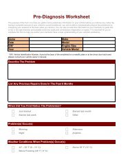
Preparation for TestingPRELIMINARY VEHICLE DIAGNOSTIC WORKSHEETPRELIMINARY VEHICLE DIAGNOSTIC WORKSHEETThe purpose of this form is to help you gather preliminary information onyour vehicle before you retrieve codes. By having a complete account ofyour vehicle's current problem(s), you will be able to systematicallypinpoint the problem(s) by comparing your answers to the fault codesyou retrieve. You can also provide this information to your mechanic toassist in diagnosis and help avoid costly and unnecessary repairs. It isimportant for you to complete this form to help you and/or yourmechanic have a clear understanding of your vehicle's problems.NAME:DATE:VIN*:YEAR:MAKE:MODEL:ENGINE SIZE:VEHICLE MILEAGE:*VIN: Vehicle Identification Number, found at the base of the windshieldon a metallic plate, or at the driver door latch area (consult your vehicleowner's manual for location).TRANSMISSION:❏❏AutomaticManualPlease check all applicable items in each category.DESCRIBE THE PROBLEM:28 CarScan+ ABS/SRS
Preparation for TestingPRELIMINARY VEHICLE DIAGNOSTIC WORKSHEETWHEN DID YOU FIRST NOTICE THE PROBLEM:❏ Just Started❏ Started Last Week❏ Started Last Month❏ Other:LIST ANY REPAIRS DONE IN THE PAST SIX MONTHS:mPROBLEMS STARTING❏ No symptoms❏Will not crankENGINE QUITS OR STALLS❏ No symptoms❏❏❏Right after startingWhen shifting into gearDuring steady-speeddrivingIDLING CONDITIONS❏ No symptoms❏❏Is too slow at all timesIs too fastRUNNING CONDITIONS❏ No symptoms❏❏❏❏❏Runs roughLacks powerBucks and jerksPoor fuel economyHesitates or stumbles onaccelerations❏❏❏❏❏❏❏❏❏❏❏❏❏❏Cranks, but will not startStarts, but takes a longtimeRight after vehiclecomes to a stopWhile idlingDuring accelerationWhen parkingIs sometimes too fast ortoo slowIs rough or unevenFluctuates up and downBackfiresMisfires or cuts outEngine knocks, pings orrattlesSurgesDieseling or run-onCarScan+ ABS/SRS 29
Preparation for TestingPRELIMINARY VEHICLE DIAGNOSTIC WORKSHEETAUTOMATIC TRANSMISSION PROBLEMS (if applicable)❏ No symptoms❏ Vehicle does not move❏ Shifts too early or too latewhen in gear❏ Changes gear incorrectly❏ Jerks or bucksPROBLEM OCCURS❏ Morning ❏ Afternoon ❏ AnytimeENGINE TEMPERATURE WHEN PROBLEM OCCURS❏ Cold ❏ Warm ❏ HotDRIVING CONDITIONS WHEN PROBLEM OCCURS❏ Short - less than 2 miles❏ With headlights on❏ 2 - 10 miles❏ During acceleration❏ Long - more than 10 miles❏ Mostly driving downhill❏ Stop and go❏ Mostly driving uphill❏ While turning❏ Mostly driving level❏ While braking❏ Mostly driving curvy❏ At gear engagementroads❏ With A/C operating❏ Mostly driving roughroadsDRIVING HABITS❏ Mostly city driving❏ Drive less than 10 miles per day❏ Highway❏ Drive 10 to 50 miles per day❏ Park vehicle inside❏ Drive more than 50 miles per❏ Park vehicle outsidedayGASOLINE USED❏ 87 Octane❏ 89 Octane❏❏91 OctaneMore than 91 OctaneWEATHER CONDITIONS WHEN PROBLEM OCCURS❏ 32 - 55° F (0 - 13° C)❏ Above 55° F (13° C)❏ Below freezing (32° F / 0° C)CHECK ENGINE LIGHT / DASH WARNING LIGHT❏ Sometimes ON ❏ Always ON ❏ Never ONPECULIAR SMELLS❏ "Hot"❏ Sulfur ("rotten egg")❏ Burning rubberSTRANGE NOISES❏ Rattle❏ Knock❏❏❏❏❏GasolineBurning oilElectricalSqueakOther30 CarScan+ ABS/SRS
Preparation for TestingBEFORE YOU BEGINBEFORE YOU BEGINThe Scan Tool aids in monitoringelectronic- and emissionsrelatedfaults in your vehicle andretrieving fault codes related tomalfunctions in these systems.Mechanical problems such aslow oil level or damaged hoses,wiring or electrical connectors can cause poor engine performance andmay also cause a fault code to set. Fix any known mechanical problemsbefore performing any test. See your vehicle’s service manual or amechanic for more information.Check the following areas before starting any test:• Check the engine oil, power steering fluid, transmission fluid (ifapplicable), engine coolant and other fluids for proper levels. Top offlow fluid levels if needed.• Make sure the air filter is clean and in good condition. Make sure allair filter ducts are properly connected. Check the air filter ducts forholes, rips or cracks.• Make sure all engine belts are in good condition. Check for cracked,torn, brittle, loose or missing belts.• Make sure mechanical linkages to engine sensors (throttle, gearshiftposition, transmission, etc.) are secure and properly connected. Seeyour vehicle’s service manual for locations.• Check all rubber hoses (radiator) and steel hoses (vacuum/fuel) forleaks, cracks, blockage or other damage. Make sure all hoses arerouted and connected properly.• Make sure all spark plugs are clean and in good condition. Checkfor damaged, loose, disconnected or missing spark plug wires.• Make sure the battery terminals are clean and tight. Check forcorrosion or broken connections. Check for proper battery andcharging system voltages.• Check all electrical wiring and harnesses for proper connection.Make sure wire insulation is in good condition, and there are no barewires.• Make sure the engine is mechanically sound. If needed, perform acompression check, engine vacuum check, timing check (ifapplicable), etc.CarScan+ ABS/SRS 31
Preparation for TestingVEHICLE SERVICE MANUALSVEHICLE SERVICE MANUALSAlways refer to the manufacturer’s service manual for your vehiclebefore performing any test or repair procedures. Contact your local cardealership, auto parts store or bookstore for availability of thesemanuals. The following companies publish valuable repair manuals:• Haynes Publications861 Lawrence DriveNewbury Park, California 91320Phone: 800-442-9637Web: www.haynes.com• Mitchell 114145 Danielson StreetPoway, California 92064Phone: 888-724-6742Web: www.m1products.com• Motor Publications5600 Crooks Road, Suite 200Troy, Michigan 48098Phone: 800-426-6867Web: www.motor.comFACTORY SOURCESFord, GM, Chrysler, Honda, Isuzu, Hyundai and Subaru ServiceManuals• Helm Inc.14310 Hamilton AvenueHighland Park, Michigan 48203Phone: 800-782-4356Web: www.helminc.com32 CarScan+ ABS/SRS
Using the Scan ToolCODE RETRIEVAL PROCEDURECODE RETRIEVAL PROCEDURERetrieving and using Diagnostic Trouble Codes (DTCs) fortroubleshooting vehicle operation is only one part of anoverall diagnostic strategy.Never replace a part based only on the DTC definition.Each DTC has a set of testing procedures, instructions andflow charts that must be followed to confirm the location ofthe problem. This information is found in the vehicle'sservice manual. Always refer to the vehicle's service manualfor detailed testing instructions.Check your vehicle thoroughly before performingany test. See BEFORE YOU BEGIN on page 31 fordetails.ALWAYS observe safety precautions whenever working on avehicle. See SAFETY PRECAUTIONS on page 3 for moreinformation.1. Turn the ignition off.2. Locate the vehicle's 16-pin Data LinkConnector (DLC). See page 5 forconnector location.Some DLCs have a plastic cover thatmust be removed before connectingthe Scan Tool cable connector.If the Scan Tool is ON, turn it OFF bypressing the POWER/LINKbutton BEFORE connecting the ScanTool to the DLC.3. Connect the Scan Tool cable connector to the vehicle’s DLC. Thecable connector is keyed and will only fit one way.• If you have problems connecting the cable connector to the DLC,rotate the connector 180° and try again.• If you still have problems, check the DLC on the vehicle and onthe Scan Tool. Refer to your vehicle’s service manual to properlycheck the vehicle’s DLC.4. Turn the ignition on. DO NOT start the engine.5. When the Scan Tool’s cable connector is properly connected to thevehicle’s DLC, the unit automatically turns ON.CarScan+ ABS/SRS 33
Using the Scan ToolCODE RETRIEVAL PROCEDURE• If the unit does not power on automatically when connected tothe vehicle’s DLC connector, it usually indicates there is nopower present at the vehicle’s DLC connector. Check your fusepanel and replace any burned-out fuses.• If replacing the fuse(s) does not correct the problem, consultyour vehicle’s repair manual to identify the proper computer(PCM) fuse/circuit, and perform any necessary repairs beforeproceeding.6. The Scan Tool will automatically start acheck of the vehicle’s computer todetermine which type of communicationprotocol it is using. When the Scan Toolidentifies the computer’s communicationprotocol, a communication link isestablished. The protocol type used by thevehicle’s computer is shown on the display.A PROTOCOL is a set of rules andprocedures for regulating datatransmission between computers,and between testing equipmentand computers. As of this writing,five different types of protocols(ISO 9141, Keyword 2000, J1850PWM, J1850 VPW and CAN) are inuse by vehicle manufacturers. TheScan Tool automatically identifiesthe protocol type and establishes acommunication link with the vehicle’scomputer.7. After approximately 10~60 seconds, the Scan Tool will retrieve anddisplay any Diagnostic Trouble Codes, Monitor Status and FreezeFrame Data retrieved from the vehicle’s computer memory.• If the Scan Tool fails to link to thevehicle’s computer a “Linking Failed”message shows on the Scan Tool’sdisplay.- Verify the connection at the DLC,and verify the ignition is ON.- Turn the ignition OFF, wait 5seconds, then turn back ON to resetthe computer.- Ensure your vehicle is OBD2 compliant. See VEHICLESCOVERED on page 5 for vehicle compliance verificationinformation.34 CarScan+ ABS/SRS
Using the Scan ToolCODE RETRIEVAL PROCEDURE• The Scan Tool will display a code onlyif codes are present in the vehicle’scomputer memory. If no codes arepresent, the message “No PowertrainDTCs or Freeze Frame Data presentlystored in the vehicle’s computer. Pressthe DTC button to view your EnhancedDTC’s display. Press thebutton to enter the “enhanced” mode(see THE ENHANCED MAIN MENUon page 39).• The Scan Tool is capable of retrieving and storing up to 32codes in memory, for immediate or later viewing.8. To read the display:Refer to DISPLAY FUNCTIONS on page 8 for a description ofdisplay elements.• A visible icon indicates that the Scan Tool is being poweredthrough the vehicle’s DLC connector.• A visible icon indicates that the Scan Tool is linked to(communicating with) the vehicle’s computer.• The I/M Monitor Status icons indicate the type and number ofMonitors the vehicle supports, and provides indications of thecurrent status of the vehicle’s Monitors. A solid Monitor iconindicates the associated Monitor has run and completed itstesting. A blinking Monitor icon indicates the associated Monitorhas not run and completed its testing.• The upper right hand corner of thedisplay shows the number of the codecurrently being displayed, the totalnumber of codes retrieved, and whetheror not the displayed code commandedthe MIL on. If the code being displayedis a PENDING code, the PENDING iconis shown. If the code being displayed isa PERMANENT code, the PERMA-NENT icon is shown.• The Diagnostic Trouble Code (DTC) and related code definitionare shown in the lower section of the display.In the case of long code definitions, a small arrow is shown in theupper/lower right-hand corner of the Scan Tool display area toindicate the presence of additional information. Use the andbuttons, as necessary, to view the additional information.If a definition for the currently displayed code is not available,an advisory message shows on the Scan Tool’s display.9. Read and interpret Diagnostic Trouble Codes/system conditionusing the display and the green, yellow and red LEDs.CarScan+ ABS/SRS 35
Using the Scan ToolCODE RETRIEVAL PROCEDUREThe green, yellow and red LEDs are used (with the display) asvisual aids to make it easier to determine engine systemconditions.• Green LED – Indicates that all enginesystems are “OK” and operatingnormally. All monitors supported by thevehicle have run and performed theirdiagnostic testing, and no troublecodes are present. All Monitor iconswill be solid.• Yellow LED – Indicates one of thefollowing conditions:A. A PENDING CODE IS PRESENT – Ifthe yellow LED is illuminated, it mayindicate a Pending code is present.Check the Scan Tool’s display forconfirmation. A Pending code isconfirmed by the presence of anumeric code and the word PENDINGon the Scan Tool’s display.B. MONITOR NOT RUN STATUS – Ifthe Scan Tool’s display shows a zero(indicating there are no DTC’s presentin the vehicle’s computer memory),but the yellow LED is illuminated, itmay be an indication that some of theMonitors supported by the vehiclehave not yet run and completed theirdiagnostic testing. Check the ScanTool’s display for confirmation. AllMonitor icons that are blinking havenot yet run and completed theirdiagnostic testing; all Monitor iconsthat are solid have run andcompleted their diagnostic testing.• Red LED – Indicates there is aproblem with one or more of thevehicle’s systems. The red LED is alsoused to indicate that DTC(s) arepresent (displayed on the Scan Tool’sscreen). In this case, the MalfunctionIndicator (Check Engine) lamp on thevehicle’s instrument panel will beilluminated.• DTC’s that start with “P0”, “P2” andsome “P3” are considered Generic (Universal). All GenericDTC definitions are the same on all OBD2 equipped vehicles.The Scan Tool automatically displays the code definitions (ifavailable) for Generic DTC’s.36 CarScan+ ABS/SRS
Using the Scan ToolCODE RETRIEVAL PROCEDURE• DTC’s that start with “P1” and some “P3”are Manufacturer specific codes and theircode definitions vary with each vehiclemanufacturer. When a Manufacturerspecific DTC is retrieved, the LCDdisplay shows a list of vehiclemanufacturers. Use the UP andDOWN buttons, as necessary, tohighlight the appropriate manufacturer,then press the ENTER button todisplay the correct code definition foryour vehicle. A confirmation messageshows on the LCD display.- If the correct manufacturer is shown,press the ENTER button tocontinue.- If the correct manufacturer is not shown, press thebutton to return to the list of vehicle manufacturers.If the manufacturer for your vehicle is not listed, use the UPand DOWN buttons, as necessary, to select Othermanufacturer and press the ENTER button for additionalDTC information.If the definition for the currentlydisplayed code is not available, anadvisory message shows on theScan Tool’s LCD display.10. If more than one DTC was retrieved, andto view Freeze Frame Data, press andrelease the button, as necessary.• Each time the button is pressed and released, the ScanTool will scroll and display the next DTC in sequence until allDTCs in its memory have displayed.• Freeze Frame Data (if available) will display after DTC #1.Whenever the Scroll function is used to view additionalDTCs and Freeze Frame Data, the Scan Tool'scommunication link with the vehicle's computerdisconnects. To re-establish communication, press thePOWER/LINK button again.• In OBD2 systems, when an emissionsrelatedengine malfunction occurs thatcauses a DTC to set, a record orsnapshot of engine conditions at the timethat the malfunction occurred is alsosaved in the vehicle’s computer memory.The record saved is called Freeze Framedata. Saved engine conditions include,but are not limited to: engine speed,CarScan+ ABS/SRS 37
Using the Scan ToolCODE RETRIEVAL PROCEDUREopen or closed loop operation, fuel system commands, coolanttemperature, calculated load value, fuel pressure, vehicle speed, airflow rate, and intake manifold pressure.If more than one malfunction is present that causes more thanone DTC to be set, only the code with the highest priority willcontain Freeze Frame data. The code designated “01” on theScan Tool display is referred to as the PRIORITY code, andFreeze Frame data always refers to this code. The prioritycode is also the one that has commanded the MIL on.Retrieved information can be uploaded to a Personal Computer(PC) with the use of optional software (see instructions includedwith the software for more information).11. When the last retrieved DTC has been displayed and thebutton is pressed, the Scan Tool enters the “enhanced” mode.• See VIEWING ENHANCED DTCs on page 40 to view enhancedDTCs for your vehicle.• If you do not wish to view enhanced DTCs, press thebutton to return to the OBD2 DTC screen.If a Manufacturer specific DTC was retrieved during thecode retrieval process, and the manufacturer selected forthe code was not Chrysler/Jeep, Ford/Mazda, GM/Isuzu,Honda/Acura, or Toyota/Lexus, pressing thebutton after display of the last retrieved DTC returns thescreen to the first retrieved DTC (the Enhanced DTCmenu is not displayed).12. Determine engine system(s) condition by viewing the Scan Tool’sdisplay for any retrieved Diagnostic Trouble Codes, code definitions,Freeze Frame data and Live Data, interpreting the green, yellow andred LEDs.• If DTC’s were retrieved and you are going to perform the repairsyourself, proceed by consulting the Vehicle’s Service RepairManual for testing instructions, testing procedures, and flowcharts related to retrieved code(s).• If you plan to take the vehicle to a professional to have itserviced, complete the PRELIMINARY VEHICLE DIAGNOSTICWORKSHEET on page 28 and take it together with the retrievedcodes, freeze frame data and LED information to aid in thetroubleshooting procedure.• To prolong battery life, the Scan Tool automatically shuts “Off”approximately three minutes after it is disconnected from thevehicle. The DTCs retrieved, captured Live Data Information,Monitor Status and Freeze Frame data (if any) will remain in theScan Tool’s memory, and may be viewed at any time by turningthe unit “On”. If the Scan Tool’s batteries are removed, or if theScan Tool is re-linked to a vehicle to retrieve codes/data, anyprior codes/data in its memory are automatically cleared.38 CarScan+ ABS/SRS
Using the Scan ToolTHE ENHANCED MAIN MENUTHE ENHANCED MAIN MENUFollowing the code retrieval procedure (see CODE RETRIEVALPROCEDURE on page 33), when the last retrieved DTC has beendisplayed and the button is pressed, the Scan Tool enters the“enhanced” mode. The “enhanced” mode provides the ability to retrieveenhanced DTCs from most Chrysler/Jeep, Ford/Mazda, GM/Isuzu,Honda/Acura and Toyota/Lexus vehicles. The types of enhanced dataavailable depends on the vehicle make.You can also retrieve Anti-Lock Brake System (ABS) DTCs, andSupplemental Restraint System (SRS) DTCs.The screen shown when the Scan Tool enters the “enhanced” modedepends on the type(s) of DTC(s) returned during the code retrieval process:• When the last retrieved DTC has beendisplayed and the button is pressed,the Enhanced Menu displays. Use the UPand DOWN buttons, as necessary,to highlight the desired option, then pressthe ENTER button to view the selectedinformation, or, press the button toreturn to the DTC screen.- If no DTCs were retrieved, or onlygeneric DTCs were retrieved, and ViewABS DTCs, View SRS DTCs or ViewEnhanced DTCs is selected, the SelectManufacturer screen displays. Use theUP and DOWN buttons, asnecessary, to highlight the appropriatemanufacturer, then press the ENTERbutton to view the selectedinformation.If the manufacturer of the vehiclefrom which codes were retrieved isnot listed, press the buttonto return to the DTC screen.Enhanced data is not available foryour vehicle.• If a Manufacturer specific DTC was retrieved,and the manufacturer selected for the codewas Chrysler, Jeep, Ford, Mazda, GeneralMotors, Isuzu, Honda, Acura, Toyota orLexus, the Select Data menu displays, asappropriate. Use the UP and DOWNbuttons, as necessary, to highlight thedesired option, the press the ENTERbutton to view the selected information, or,press the button to return to the DTCscreen.CarScan+ ABS/SRS 39
Using the Scan ToolVIEWING ENHANCED DTCs• If a Manufacturer specific DTC was retrieved,and the manufacturer selected for the codewas not Chrysler, Jeep, Ford, Mazda,General Motors, Isuzu, Honda, Acura,Toyota or Lexus, the message “This vehicledoes not support Enhanced communication”displays. Press the button to return tothe Enhanced Menu. Enhanced data is notavailable for your vehicle.To view Enhanced DTCs: Select EnhancedDTCs from the Enhanced Main Menu (thenchoose the appropriate manufacturer ifprompted). Refer to VIEWING ENHANCEDDTCs on page 40 to view enhanced DTCs foryour vehicle.To view ABS DTCs: Select ABS DTCs fromthe Enhanced Main Menu (then choose theappropriate manufacturer if prompted). Referto VIEWING ABS DTCs on page 48 to viewABS DTCs for your vehicle.To view SRS DTCs: Select SRS DTCs fromthe Enhanced Main Menu (then choose theappropriate manufacturer if prompted). Referto VIEWING SRS DTCs on page 51 to viewSRS DTCs for your vehicle.VIEWING ENHANCED DTCsRefer to the appropriate paragraph to view enhanced data for yourvehicle:• Chrysler/Jeep......................................... page 40• Ford/Mazda............................................ page 42• GM/Isuzu................................................ page 44• Honda/Acura .......................................... page 45• Toyota/Lexus ......................................... page 47Chrysler/Jeep Enhanced DTCsWhen the Scan Tool enters the “enhanced” mode (and Chrysler/Jeepis selected, if prompted), the Chrysler Enhanced menu displays. Youmay view either “Engine DTCs” or “Transmission DTCs.”1. Use the UP and DOWN buttons, as necessary, to highlightthe desired option, then press the ENTER button.40 CarScan+ ABS/SRS
Using the Scan ToolVIEWING ENHANCED DTCsTransmission DTCs are not supportedon most Chrysler/Jeep vehiclesmanufactured prior to 2002.• A “One moment please” messagedisplays while the Scan Tool retrievesthe selected DTCs.• If the Scan Tool fails to link to thevehicle’s computer, a “Linking Failed”message shows on the Scan Tool’sdisplay.- Verify the ignition is ON, then pressthe POWER/LINK button tocontinue.2. To read the display:Refer to DISPLAY FUNCTIONS onpage 8 for a description of LCDdisplay elements.• A visible icon indicates that theScan Tool is being powered throughthe vehicle’s DLC connector.• The upper right hand corner of thedisplay shows the number of the codecurrently being displayed, the totalnumber of codes retrieved.• The Diagnostic Trouble Code (DTC)and related code definition are shownin the lower section of the LCD display.I/M MONITOR STATUS icons are not displayed whenviewing enhanced DTCs.In the case of long code definitions, or when viewingFreeze Frame data, a small arrow is shown in theupper/lower right-hand corner of the code display areato indicate the presence of additional information. Usethe and buttons, as necessary, to view theadditional information.• The Scan Tool will display a code only ifcodes are present in the vehicle’scomputer memory. If no codes arepresent, a “No Enhanced DTC’s arepresently stored in the vehicle’scomputer” is displayed. Press thebutton to return to the Chrysler Enhancedmenu.3. If more than one code was retrieved press the button, asnecessary, to display additional codes one at a time.CarScan+ ABS/SRS 41
Using the Scan ToolVIEWING ENHANCED DTCs• Whenever the Scroll function is used to view additional codes,the Scan Tool’s communication link with the vehicle’s computerdisconnects. To re-establish communication, press thePOWER/LINK button again.4. When the last retrieved DTC has been displayed and thebutton is pressed, the Scan Tool returns to the Chrysler Enhancedmenu.• To view additional enhanced DTCs, repeat steps 1 through 4, above.• To exit the enhanced mode, press the button. The ScanTool returns to the Main Menu.Ford/Mazda Enhanced DTCsMazda Enhanced DTCs are available for Mazda-brandedFord vehicles only.When the Scan Tool enters the “enhanced” mode (and Ford/Mazda isselected, if prompted), the Ford/Mazda Enhanced menu displays. Youmay view DTCs for either the “Continuous Memory Test”, “KOEO (KeyOn Engine Off) Test” or “KOER (Key On Engine Running) Test.”1. Use the UP and DOWN buttons,as necessary, to highlight the desiredoption, then press the ENTER button.When choosing to view KOERTest DTCs, start the vehicle’sengine before making yourselection.• A “One moment please” messagedisplays, while the Scan Tool retrievesthe selected DTCs.• If the Scan Tool fails to link to thevehicle’s computer, a “Linking Failed”message shows on the Scan Tool’sDisplay.- Verify the ignition is ON, then pressthe POWER/LINK button tocontinue.• If the KOER Test was selected, andthe vehicle’s engine is not running, anadvisory message shows on the ScanTool’s display.- Press the ENTER button toreturn to the Ford/Mazda Enhancedmenu.2. An “instructional” message shows on the Scan Tool’s display.Perform test procedures as appropriate.42 CarScan+ ABS/SRS
Using the Scan ToolVIEWING ENHANCED DTCs• If the Continuous Memory or KOEOtest was selected, turn the ignition OFF,then back ON. Press the ENTERbutton to start the test.- A “One moment please” messagedisplays while the test is in progress.• If the KOER test was selected, pressthe ENTER button to continue.- A “One moment please” messagedisplays while the test is in progress.- Turn the steering wheel to the right,then release.- Press and release the brake pedal.- Cycle the overdrive switch (ifequipped).3. To read the display:Refer to DISPLAY FUNCTIONS on page 8 for a description ofLCD display elements.• A visible icon indicates that theScan Tool is being powered throughthe vehicle’s DLC connector.• The upper right hand corner of thedisplay shows the number of the codecurrently being displayed, the totalnumber of codes retrieved.• The Diagnostic Trouble Code (DTC)and related code definition are shownin the lower section of the LCD display.I/M MONITOR STATUS icons are not displayed whenviewing enhanced DTCs.In the case of long code definitions, or when viewingFreeze Frame data, a small arrow is shown in theupper/lower right-hand corner of the code display areato indicate the presence of additional information. Usethe and buttons, as necessary, to view theadditional information.• The Scan Tool will display a code onlyif codes are present in the vehicle’scomputer memory. If no codes arepresent, a “No Enhanced DTC’s arepresently stored in the vehicle’scomputer” is displayed. Press thebutton to return to theFord/Mazda Enhanced menu.CarScan+ ABS/SRS 43
Using the Scan ToolVIEWING ENHANCED DTCs4. If more than one code was retrieved press the button, asnecessary, to display additional codes one at a time.• Whenever the Scroll function is used to view additional codes,the Scan Tool’s communication link with the vehicle’s computerdisconnects. To re-establish communication, press thePOWER/LINK button again.5. When the last retrieved DTC has been displayed and thebutton is pressed, the Scan Tool returns to the Ford/MazdaEnhanced menu.• To view additional enhanced DTCs, repeat steps 1 through 5,above.• To exit the enhanced mode, press the button. The ScanTool returns to the Main Menu.General Motors/Isuzu Enhanced DTCsWhen the Scan Tool enters the “enhanced” mode (and GeneralMotors/Isuzu is selected, if prompted), the GM/Isuzu Enhanced menudisplays. You may view the “MIL DTC”, “Current DTC”, “Fail Since ClearDTC” or “History DTC.”1. Use the UP and DOWN buttons,as necessary, to highlight the desiredoption, then press the ENTER button.• A “One moment please” messagedisplays while the Scan Tool retrievesthe selected DTCs.• If the Scan Tool fails to link to thevehicle’s computer, a “Linking Failed”message shows on the Scan Tool’sdisplay.- Verify the ignition is ON, then pressthe POWER/LINK button tocontinue.2. To read the display:Refer to DISPLAY FUNCTIONS on page 8 for a description ofLCD display elements.• A visible icon indicates that theScan Tool is being powered throughthe vehicle’s DLC connector.• The upper right hand corner of thedisplay shows the number of the codecurrently being displayed, the totalnumber of codes retrieved.44 CarScan+ ABS/SRS
Using the Scan ToolVIEWING ENHANCED DTCs• The Diagnostic Trouble Code (DTC) and related code definitionare shown in the lower section of the LCD display.I/M MONITOR STATUS icons are not displayed whenviewing enhanced DTCs.In the case of long code definitions, or when viewingFreeze Frame data, a small arrow is shown in theupper/lower right-hand corner of the code display areato indicate the presence of additional information. Usethe and buttons, as necessary, to view theadditional information.• The Scan Tool will display a code onlyif codes are present in the vehicle’scomputer memory. If no codes arepresent, a “No Enhanced DTC’s arepresently stored in the vehicle’scomputer” is displayed. Press thebutton to return to the GMEnhanced menu.3. If more than one code was retrieved press the button, asnecessary, to display additional codes one at a time.• Whenever the Scroll function is used to view additional codes,the Scan Tool’s communication link with the vehicle’s computerdisconnects. To re-establish communication, press thePOWER/LINK button again.4. When the last retrieved DTC has been displayed and thebutton is pressed, the Scan Tool returns to the GM/Isuzu Enhancedmenu.• To view additional enhanced DTCs, repeat steps 1 through 4,above.• To exit the enhanced mode, press the button. The ScanTool returns to the Main Menu.Honda/Acura Enhanced DTCsWhen the Scan Tool enters the “enhanced”mode (and Honda/Acura is selected, ifprompted), the Honda Acura Enhanced menudisplays. Depending on the protocol used tocommunicate with your vehicle, the Honda/AcuraEnhanced menu provides options to view:• Confirmed DTCs or Temporary DTCs• Confirmed DTCs or Pending DTCs1. Use the UP and DOWN buttons,as necessary, to highlight the desiredoption, then press the ENTER button.CarScan+ ABS/SRS 45
Using the Scan ToolVIEWING ENHANCED DTCs• A “One moment please” message displays while the Scan Toolretrieves the selected DTCs.• If the Scan Tool fails to link to thevehicle’s computer, a “Linking Failed”message shows on the Scan Tool’sdisplay.- Verify the ignition is ON, then pressthe POWER/LINKbutton tocontinue.2. To read the display:Refer to DISPLAY FUNCTIONS on page 8 for a description ofLCD display elements.• A visible icon indicates that theScan Tool is being powered throughthe vehicle’s DLC connector.• The upper right hand corner of thedisplay shows the number of the codecurrently being displayed, the totalnumber of codes retrieved.• The Diagnostic Trouble Code (DTC)and related code definition are shownin the lower section of the LCD display.I/M MONITOR STATUS icons are not displayed whenviewing enhanced DTCs.In the case of long code definitions, or when viewingFreeze Frame data, a small arrow is shown in theupper/lower right-hand corner of the code display areato indicate the presence of additional information. Usethe and buttons, as necessary, to view theadditional information.• The Scan Tool will display a code only ifcodes are present in the vehicle’scomputer memory. If no codes arepresent, a “No Enhanced DTC’s arepresently stored in the vehicle’scomputer” is displayed. Press thebutton to return to the Honda/AcuraEnhanced menu.3. If more than one code was retrieved press the button, asnecessary, to display additional codes one at a time.• Whenever the Scroll function is used to view additional codes,the Scan Tool’s communication link with the vehicle’s computerdisconnects. To re-establish communication, press thePOWER/LINK button again.46 CarScan+ ABS/SRS
Using the Scan ToolVIEWING ENHANCED DTCs4. When the last retrieved DTC has been displayed and thebutton is pressed, the Scan Tool returns to the Honda/AcuraEnhanced menu.• To view additional enhanced DTCs, repeat steps 1 through 4, above.• To exit the enhanced mode, press the button. The ScanTool returns to the Main Menu.Toyota/Lexus Enhanced DTCsWhen the Scan Tool enters the “enhanced”mode (and Toyota/Lexus is selected, ifprompted), the Toyota/Lexus Enhanced menudisplays. Depending on the protocol used tocommunicate with your vehicle, theToyota/Lexus Enhanced menu providesoptions to view:• Current DTCs, History DTCs or PendingDTCs• Current DTCs, Historical DTCs orReadiness DTCs1. Use the UP and DOWN buttons,as necessary, to highlight the desiredoption, then press the ENTER button.• A “One moment please” messagedisplays, while the Scan Tool retrievesthe selected DTCs.• If the Scan Tool fails to link to thevehicle’s computer, a “Linking Failed”message shows on the Scan Tool’sDisplay.- Verify the ignition is ON, then pressthe POWER/LINKbutton tocontinue.2. To read the display:Refer to DISPLAY FUNCTIONS on page 8 for a description ofLCD display elements.• A visible icon indicates that the Scan Tool is being poweredthrough the vehicle’s DLC connector.• The upper right hand corner of thedisplay shows the number of the codecurrently being displayed, the totalnumber of codes retrieved.• The Diagnostic Trouble Code (DTC) andrelated code definition are shown in thelower section of the LCD display.CarScan+ ABS/SRS 47
Using the Scan ToolVIEWING ABS DTCsI/M MONITOR STATUS icons are not displayed whenviewing enhanced DTCs.In the case of long code definitions, or when viewingFreeze Frame data, a small arrow is shown in theupper/lower right-hand corner of the code display areato indicate the presence of additional information. Usethe and buttons, as necessary, to view theadditional information.• The Scan Tool will display a code only ifcodes are present in the vehicle’scomputer memory. If no codes arepresent, a “No Enhanced DTC’s arepresently stored in the vehicle’scomputer” is displayed. Press thebutton to return to the Toyota/LexusEnhanced menu.3. If more than one code was retrieved press the button, asnecessary, to display additional codes one at a time.• Whenever the Scroll function is used to view additional codes,the Scan Tool’s communication link with the vehicle’s computerdisconnects. To re-establish communication, press thePOWER/LINK button again.4. When the last retrieved DTC has been displayed and thebutton is pressed, the Scan Tool returns to the Toyota/LexusEnhanced menu.• To view additional enhanced DTCs, repeat steps 1 through 4,above.• To exit the enhanced mode, press the button. The ScanTool returns to the Main Menu.VIEWING ABS DTCsRefer to Vehicle Applications - Makes Covered (ABS) on page86 for vehicle makes covered. Please visit pro.innova.com fora complete list of vehicles covered.Reading ABS DTCs1. The screen shown when View ABS DTCs is selected from theEnhanced Main Menu (and the appropriate vehicle manufacturer isselected, if prompted) depends on the vehicle make.• For Chrysler/Jeep vehicles ONLY:The Chrysler/Jeep ABS Menu displays.Use the UP and DOWNbuttons, as necessary, to highlightRead ABS DTCs, then press theENTER button. <strong>Pro</strong>ceed to step 2.48 CarScan+ ABS/SRS
Using the Scan ToolVIEWING ABS DTCs• For GM/Isuzu vehicles ONLY: TheGM/Isuzu ABS Menu displays. Use theUP and DOWN buttons, asnecessary, to highlight the desiredoption, Current DTC or History DTC,then press the ENTER button.<strong>Pro</strong>ceed to step 2.• For Ford/Mazda, Honda/Acura andToyota/Lexus vehicles: <strong>Pro</strong>ceed tostep 2.2. A "One moment please" message displays while the Scan Toolretrieves the selected DTCs.• If the Scan Tool fails to link to thevehicle’s computer, a "Linking Failed"message shows on the Scan Tool’sdisplay.- Verify the ignition is ON, then pressthe POWER/LINK button tocontinue.• If the vehicle does not support ABScommunication, an advisory messageshows on the Scan Tool’s display. Pressthe button to return to theEnhanced Main Menu.3. To read the display:Refer to DISPLAY FUNCTIONS onpage 8 for a description of LCDdisplay elements.• A visible icon indicates that the Scan Tool is being poweredthrough the vehicle’s DLC connector.• A visible icon indicates that the Scan Tool is linked to(communicating with) the vehicle’s computer.• The upper right hand corner of thedisplay shows the number of the codecurrently being displayed, the totalnumber of codes retrieved.• The Diagnostic Trouble Code (DTC)and related code definition are shownin the lower section of the LCD display.I/M MONITOR STATUS icons are notdisplayed when viewing ABS DTCs.CarScan+ ABS/SRS 49
Using the Scan ToolVIEWING ABS DTCsIn the case of long code definitions, a small arrow is shown inthe upper/lower right-hand corner of the code display area toindicate the presence of additional information. Use the UPand DOWN buttons, as necessary, to view theadditional information.• The Scan Tool will display a code only ifcodes are present in the vehicle’scomputer memory. If no codes arepresent, a "No ABS DTC’s are presentlystored in the vehicle’s computer" isdisplayed. Press the button toreturn to the Enhanced Main Menu.4. If more than one code was retrieved pressthe button, as necessary, todisplay additional codes one at a time.• Whenever the Scroll function is used to view additional codes,the Scan Tool’s communication link with the vehicle’s computerdisconnects. To re-establish communication, press thePOWER/LINK button again.5. When the last retrieved DTC has been displayed and thebutton is pressed, the Scan Tool returns to the Enhanced Main Menu.• To exit the enhanced mode, press the button. The ScanTool returns to the Main Menu.Erasing ABS DTCsIf you plan to take the vehicle to a Service Center for repair, DO NOTerase the ABS DTCs from the vehicle’s computer. If the codes areerased, valuable information that might help the technician troubleshootthe problem will be erased.1. With the Scan Tool in ”ABS Mode” (see Reading ABS DTCs onpage 48 for details), press the ERASE button.2. A confirmation message shows on theLCD display.• If you are sure you want to proceed,press the ERASE button to erasethe ABS DTCs from the vehicle’scomputer.• If you do not want to continue with theerase process, press the buttonto exit the erase mode and return tothe Enhanced Main Menu.3. If you chose to erase ABS DTCs, a progress screen displays whilethe erase function is in progress.50 CarScan+ ABS/SRS
Using the Scan ToolVIEWING SRS DTCs• If the erase was successful, aconfirmation message shows on theLCD display. Press the POWER/LINK button to re-link the ScanTool to the vehicle.• If the erase was not successful, anadvisory message shows on the LCDdisplay. Verify that the Scan Tool isproperly connected to the vehicle’s DLCand that the ignition is on, then repeatsteps 2 and 3, above.Erasing ABS DTCs does not fix theproblem(s) that caused the code(s) tobe set. If proper repairs to correct theproblem(s) that caused the code(s) tobe set are not made, the code(s) willappear again as soon as the vehicleis driven long enough for the problemto recur.VIEWING SRS DTCsRefer to Vehicle Applications - Makes Covered (SRS) on page87 for vehicle makes covered. Please visit pro.innova.com fora complete list of vehicles covered.Reading SRS DTCs1. The screen shown when View SRS DTCs is selected from theEnhanced Main Menu (and the appropriate vehicle manufacturer isselected, if prompted) depends on the vehicle make.• For GM/Isuzu vehicles ONLY: TheGM/Isuzu ABS Menu displays. Use theUP and DOWN buttons, asnecessary, to highlight the desired option,Current DTC or History DTC, thenpress the ENTER button. <strong>Pro</strong>ceedto step 2.• For Chrysler/Jeep, Ford/Mazda,Honda/Acura and Toyota/Lexusvehicles: <strong>Pro</strong>ceed to step 2.2. A "One moment please" message displayswhile the Scan Tool retrieves the selectedDTCs.• If the Scan Tool fails to link to the vehicle’scomputer, a "Linking Failed" messageshows on the Scan Tool’s display.- Verify the ignition is ON, then press the POWER/LINKbutton to continue.CarScan+ ABS/SRS 51
Using the Scan ToolVIEWING SRS DTCs• If the vehicle does not support SRScommunication, an advisory messageshows on the Scan Tool’s display. Pressthe button to return to theEnhanced Main Menu.3. To read the display:Refer to DISPLAY FUNCTIONS onpage 8 for a description of LCDdisplay elements.• A visible icon indicates that the Scan Tool is being poweredthrough the vehicle’s DLC connector.• A visible icon indicates that theScan Tool is linked to (communicatingwith) the vehicle’s computer.• The upper right hand corner of thedisplay shows the number of the codecurrently being displayed, the totalnumber of codes retrieved.• The Diagnostic Trouble Code (DTC)and related code definition are shownin the lower section of the LCD display.I/M MONITOR STATUS icons are not displayed when viewingSRS DTCs.In the case of long code definitions, a small arrow is shown inthe upper/lower right-hand corner of the code display area toindicate the presence of additional information. Use the UPand DOWN buttons, as necessary, to view theadditional information.• The Scan Tool will display a code only ifcodes are present in the vehicle’scomputer memory. If no codes arepresent, a "No SRS DTC’s are presentlystored in the vehicle’s computer" isdisplayed. Press the button toreturn to the Enhanced Main Menu.4. If more than one code was retrieved press the button, asnecessary, to display additional codes one at a time.• Whenever the Scroll function is used to view additional codes,the Scan Tool’s communication link with the vehicle’s computerdisconnects. To re-establish communication, press the POWER/LINK button again.5. When the last retrieved DTC has been displayed and thebutton is pressed, the Scan Tool returns to the Enhanced Main Menu.• To exit the enhanced mode, press the button. The ScanTool returns to the Main Menu.52 CarScan+ ABS/SRS
Using the Scan ToolERASING DIAGNOSTIC TROUBLE CODES (DTCs)Erasing SRS DTCsIf you plan to take the vehicle to a Service Center for repair, DO NOTerase the SRS DTCs from the vehicle’s computer. If the codes areerased, valuable information that might help the technician troubleshootthe problem will be erased.1. With the Scan Tool in ”SRS Mode” (seeReading SRS DTCs on page 51 fordetails), press the ERASE button.2. A confirmation message shows on theLCD display.• If you are sure you want to proceed,press the ERASE button to erasethe SRS DTCs from the vehicle’scomputer.• If you do not want to continue with the erase process, press thebutton to exit the erase mode and return to the EnhancedMain Menu.3. If you chose to erase SRS DTCs, a progress screen displays whilethe erase function is in progress.• If the erase was successful, aconfirmation message shows on theLCD display. Press the POWER/LINK button to re-link the ScanTool to the vehicle.• If the erase was not successful, anadvisory message shows on the LCDdisplay. Verify that the Scan Tool isproperly connected to the vehicle’sDLC and that the ignition is on, thenrepeat steps 2 and 3, above.Erasing SRS DTCs does not fix theproblem(s) that caused the code(s) tobe set. If proper repairs to correct theproblem(s) that caused the code(s) tobe set are not made, the code(s) will appear again as soon as thevehicle is driven long enough for the problem to recur.ERASING DIAGNOSTIC TROUBLE CODES (DTCs)When the Scan Tool’s ERASE function is used to eraseDTCs from the vehicle's on-board computer, "FreezeFrame" data and manufacturer-specific enhanced data arealso erased.CarScan+ ABS/SRS 53
Using the Scan ToolERASING DIAGNOSTIC TROUBLE CODES (DTCs)If you plan to take the vehicle to a Service Center for repair, DO NOTerase the codes from the vehicle's computer. If the codes are erased,valuable information that might help the technician troubleshoot theproblem will also be erased.Erase DTCs from the computer's memory as follows:When DTCs are erased from the vehicle's computer memory,the I/M Readiness Monitor Status program resets the status ofall Monitors to a not run "flashing" condition. To set all of theMonitors to a DONE status, an OBD2 Drive Cycle must beperformed. Refer to your vehicle's service manual forinformation on how to perform an OBD2 Drive Cycle for thevehicle under test.The Scan Tool must be connected tothe vehicle’s DLC to erase the codesfrom the computer’s memory. If youpress the ERASE button whenthe Scan Tool is not connected to thevehicle’s DLC, the erase instructionscreen displays.The Erase function can be performedonly from the OBD2 DTC screen.The Erase function cannot beperformed while the Scan Tool is in“enhanced” mode.1. If not connected already, connect the ScanTool to the vehicle's DLC, and turn theignition "On.” (If the Scan Tool is alreadyconnected and linked to the vehicle'scomputer, proceed directly to step 4. If not,continue to step 2.)2. Turn the ignition on. DO NOT start theengine. Press and release thePOWER/LINK button to establishcommunication with the vehicle's computer.3. Press and release the ERASE button.A confirmation message shows on thedisplay.• If you are sure you want to proceed,press the ERASE button to eraseDTCs from the vehicle’s computer.• If you do not want to continue with theerase process, press the buttonto exit the erase mode.54 CarScan+ ABS/SRS
Using the Scan ToolI/M READINESS TESTING4. If you chose to erase DTCs, a progressscreen displays while the erase function isin progress.• If the erase was successful, aconfirmation message shows on thedisplay. Press the POWER/LINKbutton to return to the DTCscreen.• If the erase was not successful, anadvisory message shows on thedisplay. Verify that the Scan Tool isproperly connected to the vehicle’sDLC and that the ignition is on, thenrepeat steps 2 and 3, above.Erasing DTCs does not fix the problem(s) that caused thecode(s) to be set. If proper repairs to correct the problem thatcaused the code(s) to be set are not made, the code(s) willappear again (and the check engine light will illuminate) assoon as the vehicle is driven long enough for its Monitors tocomplete their testing.I/M READINESS TESTINGI/M is an Inspection and Maintenance program legislated by theGovernment to meet federal clean-air standards.The program requires that a vehicle be taken periodically to anEmissions Station for an "Emissions Test" or "Smog Check,” where theemissions-related components and systems are inspected and testedfor proper operation. Emissions Tests are generally performed once ayear, or once every two years.On OBD2 systems, the I/M program is enhanced by requiring vehiclesto meet stricter test standards. One of the tests instituted by the FederalGovernment is called I/M 240. On I/M 240, the vehicle under test isdriven under different speeds and load conditions on a dynamometer for240 seconds, while the vehicle's emissions are measured.Emissions tests vary depending on the geographic or regionalarea in which the vehicle is registered. If the vehicle isregistered in a highly urbanized area, the I/M 240 is probablythe type of test required. If the vehicle is registered in a ruralarea, the stricter “dynamometer type” test may not be required.I/M Readiness MonitorsI/M Readiness shows whether the various emissions-related systems onthe vehicle are operating properly and are ready for Inspection andMaintenance testing.CarScan+ ABS/SRS 55
Using the Scan ToolI/M READINESS TESTINGState and Federal Governments enacted Regulations, <strong>Pro</strong>cedures andEmission Standards to ensure that all emissions-related componentsand systems are continuously or periodically monitored, tested anddiagnosed whenever the vehicle is in operation. It also requires vehiclemanufacturers to automatically detect and report any problems or faultsthat may increase the vehicle's emissions to an unacceptable level.The vehicle's emissions control system consists of several componentsor sub-systems (Oxygen Sensor, Catalytic Converter, EGR, FuelSystem, etc.) that aid in reducing vehicle emissions.To have an efficient Vehicle Emission Control System, all the emissionsrelatedcomponents and systems must work correctly whenever thevehicle is in operation.To comply with State and Federal Government regulations, vehiclemanufacturers designed a series of special computer programs called"Monitors" that are programmed into the vehicle's computer. Each ofthese Monitors is specifically designed to run tests and diagnostics on aspecific emissions-related component or system (Oxygen Sensor,Catalytic Converter, EGR Valve, Fuel System, etc.) to ensure theirproper operation. Currently, there are a maximum of fifteen Monitorsavailable for use.Each Monitor has a specific function to test and diagnose onlyits designated emissions-related component or system. Thenames of the Monitors (Oxygen Sensor Monitor, CatalystMonitor, EGR Monitor, Misfire Monitor, etc.) describe whichcomponent or system each Monitor is designed to test anddiagnose.Emissions Inspection and Maintenance (I/M) ReadinessMonitor Status InformationI/M Readiness Monitor Status shows which of the vehicle's Monitorshave run and completed their diagnosis and testing, and which oneshave not yet run and completed testing and diagnosis of theirdesignated sections of the vehicle's emissions system.• If a Monitor was able to meet all the conditions required to enable itto perform the self-diagnosis and testing of its assigned enginesystem, it means the monitor "HAS RUN.”• If a Monitor has not yet met all the conditions required for it toperform the self-diagnosis and testing of its assigned engine system;it means the Monitor "HAS NOT RUN.”The Monitor Run/Not Run status does not show whetheror not a problem exists in a system. Monitor status onlyindicates whether a particular Monitor has or has not runand performed the self-diagnosis and testing of itsassociated system.56 CarScan+ ABS/SRS
Using the Scan ToolI/M READINESS TESTINGPerforming I/M Readiness Quick CheckWhen a vehicle first comes from the factory, all Monitorsindicate a “HAVE RUN” status. This indicates that all Monitorshave run and completed their diagnostic testing. The “HAVERUN” status remains in the computer's memory, unless theDiagnostic Trouble Codes are erased or the vehicle'scomputer memory is cleared.The Scan Tool allows you to retrieve Monitor/System Status Informationto help you determine if the vehicle is ready for an Emissions Test(Smog Check). In addition to retrieving Diagnostic Trouble Codes, theScan Tool also retrieves Monitor Run/Not Run status. This information isvery important since different areas of the state/country have differentemissions laws and regulations concerning Monitor Run/Not Run status.Before an Emissions Test (Smog Check) can be performed, yourvehicle must meet certain rules, requirements and procedures legislatedby the Federal and state (country) governments where you live.1. In most areas, one of the requirements that must be met before avehicle is allowed to be Emissions Tested (Smog Checked) is thatthe vehicle does not have any Diagnostic Trouble Codes present(with the exception of PENDING Diagnostic Trouble Codes).2. In addition to the requirement that no Diagnostic Trouble Codes bepresent, some areas also require that all the Monitors that aparticular vehicle supports indicate a "Has Run" status conditionbefore an Emissions Check may be performed.3. Other areas may only require that some (but not all) Monitorsindicate a "Has Run" status before an Emissions Test (Smog Check)may be performed.Monitors with a "Has Run" status indicate that all therequired conditions they needed to perform diagnosis andtesting of their assigned engine area (system) have beenmet, and all diagnostic testing has completed successfully.Monitors with a "Has Not Run" status have not yet met theconditions they need to perform diagnosis and testing oftheir assigned engine area (system), and have not beenable to perform diagnostic testing on that system.The green, yellow and red LEDs provide a quick way to help youdetermine if a vehicle is ready for an Emissions Test (Smog Check).Follow the instructions below to perform the Quick Check.Perform the CODE RETRIEVAL PROCEDURE as described on page33, then interpret the LED indications as follows:CarScan+ ABS/SRS 57
Using the Scan ToolI/M READINESS TESTINGInterpreting I/M Readiness Test Results1. GREEN LED - Indicates that all enginesystems are "OK" and operating normally(all Monitors supported by the vehicle haverun and performed their self-diagnostictesting). The vehicle is ready for anEmissions Test (Smog Check), and thereis a good possibility that it can be certified.2. YELLOW LED - Determine from theCODE RETRIEVAL PROCEDURE (page33) which of the two possible conditions iscausing the yellow LED to light.• If a "PENDING" Diagnostic TroubleCode is causing the yellow LED to light,it is possible that the vehicle will beallowed to be tested for emissions andcertified. Currently, most areas (states/ countries) will allow an EmissionsTest (Smog Check) to be performed ifthe only code in the vehicle's computeris a "PENDING" Diagnostic TroubleCode.• If the illumination of the Yellow LED isbeing caused by monitors that “havenot run” their diagnostic testing, thenthe issue of the vehicle being ready foran Emissions Test (Smog Check)depends on the emissions regulationsand laws of your local area.- Some areas require that all Monitorsindicate a "Has Run" status beforethey allow an Emissions Test (SmogCheck) to be performed. Otherareas only require that some, but not all, Monitors have runtheir self-diagnostic testing before an Emissions Test (SmogCheck) may be performed.- From the code retrieval procedure, determine the status ofeach Monitor (a solid Monitor icon shows Monitor "Has Run"status, a flashing Monitor icon indicates "Has Not Run" status).Take this information to an emissions professional todetermine (based on your test results) if your vehicle is readyfor an Emissions Test (Smog Check).58 CarScan+ ABS/SRS
Using the Scan ToolI/M READINESS TESTING3. RED LED - Indicates there is a problemwith one or more of the vehicle's systems.A vehicle displaying a red LED is definitelynot ready for an Emissions Test (SmogCheck). The red LED is also an indicationthat there are Diagnostic Trouble Code(s)present (displayed on the Scan Tool'sscreen). The Malfunction Indicator (CheckEngine) Lamp on the vehicle's instrumentpanel will light steady. The problem that iscausing the red LED to light must berepaired before an Emissions Test (SmogCheck) can be performed. It is also suggested that the vehicle beinspected/repaired before driving the vehicle further.If the Red LED was obtained, there is a definite problem present inthe system(s). In these cases, you have the following options.• Repair the vehicle yourself. If you are going to perform therepairs yourself, proceed by reading the vehicle service manualand following all its procedures and recommendations.• Take the vehicle to a professional to have it serviced. Theproblem(s) causing the red LED to light must be repaired beforethe vehicle is ready for an Emissions Test (Smog Check).Using the I/M Readiness Monitor Status to Confirm a RepairThe I/M Readiness Monitor Status function can be used (after repair of afault has been performed) to confirm that the repair has been performedcorrectly, and/or to check for Monitor Run Status. Use the followingprocedure to determine I/M Readiness Monitor Status:1. Using retrieved Diagnostic Trouble Codes (DTCs) and codedefinitions as a guide, and following manufacturer's repairprocedures, repair the fault or faults as instructed.2. After the fault or faults have been repaired, connect the Scan Tool tothe vehicle's DLC and erase the code or codes from the vehicle'scomputer memory.• See page 53 for procedures for ERASING DIAGNOSTICTROUBLE CODES (DTCs) from the vehicle's on-boardcomputer.• Write the codes down on a piece of paper for reference beforeerasing.3. After the erase procedure is performed, most of the Monitor icons onthe Scan Tool’s display will be flashing. Leave the Scan Toolconnected to the vehicle, and perform a Trip Drive Cycle for each"flashing" Monitor:Misfire, Fuel and Comprehensive Component Monitors runcontinuously and their icons will always be on solid, even afterthe erase function is performed.CarScan+ ABS/SRS 59
Using the Scan ToolABOUT REPAIRSOLUTIONS®• Each DTC is associated with a specific Monitor. Consult thevehicle's service manual to identify the Monitor (or Monitors)associated with the faults that were repaired. Follow themanufacturer's procedures to perform a Trip Drive Cycle for theappropriate Monitors.• While observing the Monitor icons on the Scan Tool’s display,perform a Trip Drive Cycle for the appropriate Monitor orMonitors.If the vehicle needs to be driven in order to perform a TripDrive Cycle, ALWAYS have a second person help you.One person should drive the vehicle while the otherperson observes the Monitor icons on the Scan Tool forMonitor RUN status. Trying to drive and observe the ScanTool at the same time is dangerous, and could cause aserious traffic accident.4. When a Monitor's Trip Drive Cycle is performed properly, the Monitoricon on the Scan Tool’s display changes from "flashing" to "solid,”indicating that the Monitor has run and finished its diagnostic testing.• If, after the Monitor has run, the MIL on the vehicle's dash is not lit, andno stored or pending codes associated with that particular Monitor arepresent in the vehicle's computer, the repair was successful.• If, after the Monitor has run, the MIL on the vehicle's dash lightsand/or a DTC associated with that Monitor is present in thevehicle's computer, the repair was unsuccessful. Refer to thevehicle's service manual and recheck repair procedures.ABOUT REPAIRSOLUTIONS®RepairSolutions® is a web-based service created to assist professionaltechnicians in quickly and accurately diagnosing and repairing today’svehicles. RepairSolutions® allows you to view, save, and email thediagnostic data retrieved from a vehicle’s on-board computer(s) usingan <strong>Innova</strong> <strong>Pro</strong> Scan Tool. RepairSolutions® also provides access to anextensive knowledge database including:• Verified Fixes – Find the most likely fixes reported and verified byASE Technicians for the retrieved DTCs.• Step-By-Step Repair Instructions – View available repairinstructions to properly perform the fix.• How-To-Repair Videos – Watch repair video tutorials for valuablerepair tips.• Technical Service Bulletins – Research known problems reportedby vehicle manufacturers.• Safety Recalls – Research known safety concerns applicable to avehicle.And much more. Please visit www.pro.innova.com for additionalinformation.60 CarScan+ ABS/SRS
Using the Scan ToolABOUT REPAIRSOLUTIONS®Hardware Requirements:• <strong>Innova</strong> <strong>Pro</strong> Scan Tool• Mini USB Cable (included with tool)Minimum System Operating Requirements:• Windows® PC System• Windows® XP, Windows® Vista, or Windows® 7• 128 MD Ram• Pentium III <strong>Pro</strong>cessor• One available USB port• Internet Connection• Internet Explorer 5.5, Netscape 7.0 or Firefox 1.0 browserAccessing RepairSolutions®1. Link your Scan Tool to a vehicle and retrieve diagnostic data.2. Visit pro.innova.com, download and install the latest RepairSolutions®software for your Scan Tool. Select the Support tab, then chooseTroubleshoot/Download.3. Connect the Scan Tool to your PC using a Mini USB cable (cableincluded).• Your default web browser launches automatically and connectsto the pro.innova.com website.4. Login to your RepairSolutions® account using your registered EmailAddress and Password.If you have not yet established an account, you mustregister for a FREE RepairSolutions® account beforeproceeding.CarScan+ ABS/SRS 61
Live Data ModeVIEWING LIVE DATAThe Scan Tool is a special diagnostic tool that communicates with thevehicle's computer. The Scan Tool lets you view and/or "capture"(record) "real-time" Live Data. This information includes values (volts,rpm, temperature, speed etc.) and system status information (open loop,closed loop, fuel system status, etc.) generated by the various vehiclesensors, switches and actuators.In effect the Scan Tool lets you view, in "real time", the same signalvalues generated by the sensors, actuators, switches and/or vehiclesystem status information used by the vehicle's computer whencalculating and conducting system adjustments and corrections.The real time (Live Data) vehicle operating information (values/status)that the computer supplies to the Scan Tool for each sensor, actuator,switch, etc. is called Parameter Identification (PID) Data.Each PID (sensor, actuator switch, status, etc.) has a set of operatingcharacteristics and features (parameters) that serve to identify it. TheScan Tool displays this information for each sensor, actuator, switch orstatus that is supported by the vehicle under test.WARNING: If the vehicle must be driven in order to perform atroubleshooting procedure, ALWAYS have a second personhelp you. One person should drive the vehicle while the otherperson observes the Scan Tool data. Trying to drive andoperate the Scan Tool at the same time is dangerous, andcould cause a serious traffic accident.VIEWING LIVE DATA1. While linked to the vehicle, start the engine,then press and release the button.• The “Main Menu” displays.2. Use the UP and DOWN buttons,as necessary, to highlight View Live Data,then press the ENTER button.3. Real-time Live Data (PID) informationsupported by the vehicle under testdisplays.Remember, what you are viewing is"real-time" Live Data. The values (volts,rpm, temperature, vehicle speed,system status etc) for the various PIDSdisplayed may change as the vehicle'soperating conditions change.4. A vehicle usually supports several PIDs, however, only a limitedamount of PID data can be displayed on the screen at one time. Ifadditional PID data is available, a small arrow will be shown on thedisplay. Use the the UP and DOWN buttons, as necessary,to scroll up or down to view all available PID data.62 CarScan+ ABS/SRS
Live Data ModeCUSTOMIZING LIVE DATA (PIDs)• If communication with the vehicle islost while viewing Live Data, aCommunication Lost" message showson the Scan Tool's display.5. Press and release the ENTER buttonto view the currently selected PID in “graph”mode. Press and release the ENTERbutton again to return to the PID list.6. Press and hold the ENTER button toview the “expanded” definition for thecurrently selected PID. Press and release theENTER button again to return to thePID list.7. If you experience vehicle problems, viewand/or compare the Live Data (PID)information displayed on the Scan Tool tospecifications in the vehicle's repairmanual.If desired, you can "customize" the Live Data display to show onlythose PIDs you are interested in viewing. See Customizing LiveData (PIDs) below for details. You may also choose to "capture"(record) Live Data for later viewing. See RECORDING(CAPTURING) LIVE DATA on page 64 for details.CUSTOMIZING LIVE DATA (PIDs)This feature lets you customize the Scan Tool display to show onlythose PIDs that are of interest at the current time. You can customizethe Live Data display by placing the Scan Tool in "Custom Live Data"mode and selecting only the PIDs that you wish to display. To customizethe Live Data display, proceed as follows:1. While linked to the vehicle, start the engine,then press and release the button.• The “Main Menu” displays.2. Use the UP and DOWN buttons,as necessary, to highlight Live Data Menu,then press the ENTER button.• The “Live Data” menu displays.3. Use the UP and DOWN buttons,as necessary, to highlight “Custom LiveData”, then press the ENTER button.CarScan+ ABS/SRS 63
Live Data ModeRECORDING (CAPTURING) LIVE DATA• The "Custom Live Data" menu displays,with the first PID in the menuhighlighted.4. Use the UP and DOWN buttonsto scroll through the available PIDs. Whenthe PID you wish to display is highlighted,press the ENTER button to select it (a"checkmark" will show in the checkbox tothe right of the PID to confirm yourselection). Repeat the procedure until onlythe PIDs you want to display have all been selected.• To deselect a currently selected PID, highlight the PID, thenpress the ENTER button. The checkmark will be removedfrom the checkbox.5. When you are finished making your selection(s), scroll to the end ofthe PID list and highlight the word DONE, then press the ENTERbutton.• The Scan Tool is now in "Custom Live Data" mode. Only thePIDs you selected are shown on the Scan Tools display.6. To exit the "Custom Live Data" mode, press the button untilthe “Main Menu” displays.RECORDING (CAPTURING) LIVE DATAYou can record and save several frames of Live Data information foreach PID supported by the vehicle in the Scan Tool's memory.Recorded Live Data can serve as valuable information to help you in thetroubleshooting of vehicle problems.There are two ways that the Scan Tool can "record" Live Data:• Record by DTC Trigger• Record by Manual TriggerIf the POWER/LINK button is pressed at any time whilein Live Data mode, any stored (recorded) Live Data will becleared (erased) from the Scan Tool’s memory.Record by DTC TriggerThis function automatically records (captures) Live Data informationwhen a DTC sets and saves it in the Scan Tool’s memory. The recorded(captured) data can be a valuable troubleshooting aid, particularly if youare experiencing a fault that is causing a DTC to set.1. While linked to the vehicle, start the engine,then press and release the button.• The “Main Menu” displays.64 CarScan+ ABS/SRS
Live Data ModeRECORDING (CAPTURING) LIVE DATA2. Use the UP and DOWN buttons,as necessary, to highlight Live DataMenu, then press the ENTER button.• The “Live Data” menu displays.3. Use the UP and DOWN buttons,as necessary, to highlight “Record LiveData”, then press the ENTER button.4. Use the UP and DOWN buttons,as necessary, to highlight “Record by DTCtrigger”, then press the ENTER button.• If DTCs are presently stored in thevehicle’s computer, an advisorymessage displays. Use the UPand DOWN buttons, as necessary,to highlight Erase DTCs, then pressthe ENTER button to erase DTCsfrom the vehicle’s computer. When theErase process is complete, the“Record by DTC Trigger” screendisplays.5. When the "Record by DTC Trigger" screen displays, select thedesired trigger point as follows:The Scan Tool is capable of recording approximately 100 framesof Live Data. Record by DTC trigger lets you select the point intime at which you wish the Scan Tool to begin recording Live Data.You can set the trigger point to record the 100 frames of databefore an event (when the DTC sets), after the event, or in themiddle (50 frames before and 50 frames after the event.• Beginning - records approximately100 frames of Live Data after the DTCsets.• Middle - records approximately 50frames of Live Data before and 50frames after the DTC sets.• End - records approximately 100frames of Live Data before the DTCsets.6. Use the UP and DOWN buttons,as necessary, to select the desired triggerpoint, then press the ENTER button.• A "One moment please. . ." messageshows on the display. When the ScanTool is ready to record Live Data, the"Record Live Data" screen displays.CarScan+ ABS/SRS 65
Live Data ModeRECORDING (CAPTURING) LIVE DATA7. Put the engine in the operating condition that causes the DTC to set.• If necessary, drive the vehicle until you reach the vehicle speedat which the problem occurs.8. When the Scan Tool detects a fault thatcauses a DTC to set, it automaticallyrecords and saves approximately 20frames of Live Data information in itsmemory (according to your triggerselection) for each PID supported by thevehicle.• All three LEDs will blink for threeseconds to indicate that Live Data isbeing recorded, and a "One momentplease..." message shows on thedisplay, along with the number of theframe being recorded.• When recording is complete, aconfirmation screen displays, asking ifyou would like to view the recordeddata. Use the UP and DOWNbuttons, as necessary, to select Yes orNo, as desired, then press the ENTERbutton.If Yes is selected, the Scan Tool enters "Playback" mode fromwhich you can view a frame-by-frame playback of recordedLive Data (see LIVE DATA PLAYBACK on page 68 for details).If No is selected, the display returns to the "Main Menu".9. You can exit the "Record Live Data Mode" at any time by pressingthe button until the "Main Menu" displays.If desired, you can transfer the recorded Live Data informationto a personal computer with the use of optional software (seeinstructions included with the software for more information).Record by Manual TriggerThis option lets you select the precise time at which the Live Datarecording will occur. Record by Manual Trigger can be a very valuablediagnostic tool when troubleshooting intermittent problems that do notmeet the requirements for a DTC to set. Even though a DTC is notpresent, the intermittent problems will sometimes manifest themselvesbriefly, for a few fractions of a second and/or only at certain vehiclespeeds or vehicle operating conditions.1. While linked to the vehicle, start the engine,then press and release the button.• The “Main Menu” displays.2. Use the UP and DOWN buttons,as necessary, to highlight Live DataMenu, then press the ENTER button.66 CarScan+ ABS/SRS
Live Data ModeRECORDING (CAPTURING) LIVE DATA• The “Live Data” menu displays.3. Use the UP and DOWN buttons,as necessary, to highlight “Record LiveData”, then press the ENTER button.• The "Record Live Data Menu" displays.4. Use the UP and DOWN buttons,as necessary, to highlight “Record bymanual trigger”, then press the ENTERbutton.5. When the "Record by Manual Trigger"screen displays, select the desired triggerpoint as follows:The Scan Tool is capable of recording approximately 100frames of Live Data. Record by DTC trigger lets you select thepoint in time at which you wish the Scan Tool to beginrecording Live Data. You can set the trigger point to record the100 frames of data before an event (when the DTC was set),after the event, or in the middle (50 frames before and 50frames after the event.• Beginning - records approximately100 frames of Live Data after theENTER button was pressed.• Middle - records approximately 50frames of Live Data before and 50frames after the ENTER buttonwas pressed.• End - records approximately 100frames of Live Data before the ENTERbutton was pressed.6. Use the UP and DOWN buttons,as necessary, to select the desired triggerpoint, then press the ENTER button.• A "One moment please. . ." messageshows on the display. When the ScanTool is ready to record Live Data, the"Record Live Data" screen displays.7. Put the engine in the operating condition where the problemmanifests itself.• If necessary, drive the vehicle until you reach the vehicle speedat which the problem occurs.8. When the problem occurs, press and release the ENTER button.CarScan+ ABS/SRS 67
Live Data ModeLIVE DATA PLAYBACK• All three LEDs will blink for threeseconds to indicate that Live Data isbeing recorded, and a "One momentplease. . ." message shows on thedisplay, along with the number of theframe being recorded.• When recording is complete, aconfirmation screen displays, asking ifyou would like to view the recordeddata. Use the UP and DOWNbuttons, as necessary, to select Yes orNo, as desired, then press the ENTERbutton.If Yes is selected, the Scan Tool enters "Playback" mode fromwhich you can view a frame-by-frame playback of recorded LiveData (see LIVE DATA PLAYBACK on page 68 for details). If Nois selected, the display returns to the "Main Menu".9. You can exit the "Record Live Data Mode" at any time by pressing thebutton until the "Main Menu" displays.If desired, you can transfer the recorded Live Data informationto a personal computer with the use of optional software (seeinstructions included with the software for more information).Important Information1. When Live Data capture is initiated, the green, yellow and red LEDson the Scan Tool will flash three times to indicate that Live Data isbeing saved to the Scan Tool's memory.LIVE DATA PLAYBACKOnce Live Data has been recorded, it is saved in the Scan Tool'smemory. You can view recorded Live Data immediately after recordingby selecting Yes from the Record Live Data confirmation screen (seeRECORDING (CAPTURING) LIVE DATA on page 64 for moreinformation), or you can view it later using the "Playback" function.1. With the Scan Tool not connected to a vehicle, press thePOWER/LINK button.• The "To Link" screen shows on theScan Tool's display.2. Press the button to place the ScanTool in "Live Data Playback" mode.• The display shows the recorded LiveData, beginning with the "trigger" frame.68 CarScan+ ABS/SRS
Live Data ModeLIVE DATA PLAYBACKWhen you select Yes from the Record Live Data confirmationscreen, the Scan Tool enters the "Live Data Playback" mode,and the display shows the recorded Live Data, beginning withthe "trigger" frame.• A vehicle usually supports several PIDs, however, only a limitedamount of PID data can be displayed on the screen at one time.If additional PID data is available, a small arrow will be shown onthe display. Use the UP and DOWN buttons, asnecessary, to scroll up or down to view all available PID data.• When viewing recorded Live Data, look for any irregularities in anyof the PID values/signal information (LTFT %, RPM, MAP, TEMP,etc.). If any PIDs are not within specification, or irregularities aredetected, follow the procedures in the vehicle's service repairmanual to perform additional troubleshooting and repair.When recorded Live Data is played back, all available PIDsare shown, even if you have customized the Live Dataselections.If there is no Live Data currently stored in the Scan Tool'smemory, an advisory message shows on the display. Pressthe button to exit the "Live Data Playback" mode.3. When you have viewed all PID information for the current frame ofLive Data, use the DOWN button to scroll to the end of the PIDlist. Highlight Next Frame or Previous Frame, as desired, thenpress the ENTER button.4. When you have finished viewing the recorded Live Data, exit the“Live Data Playback” mode using the appropriate procedure shownbelow:• If the Scan Tool is connected to a vehicle, use the DOWNbutton to scroll to the end of the PID list, highlight Exit Playback,then press the ENTER button.• If the Scan Tool is not connected to a vehicle, press thebutton.CarScan+ ABS/SRS 69
Additional TestsSPECIAL TEST MENUIn addition to retrieving Diagnostic Trouble Codes (DTCs) and viewing LiveData, you can use the Scan Tool to perform additional diagnostic tests, toview diagnostic and vehicle information stored in your vehicle's on-boardcomputer, and to configure the Scan Tool for your particular needs.SPECIAL TEST MENUAdditional tests are accessed through the“Special Test Menu.” The following functionsare available from the "Special Test Menu:"• O2 Sensor Test - Retrieves and displaysO2 sensor monitor test results from yourvehicle's on-board computer.• Non-Continuous Test - Retrieves anddisplays test results for emission-relatedpowertrain components and systems thatare not continuously monitored.• EVAP Leak Test - Performs a leak test forthe vehicle's EVAP system.1. Start the engine.2. Press and release the button.• The “Main Menu” displays.3. Use the UP and DOWN buttons,as necessary, to highlight Special Test,then press the ENTER button.• The “Special Test Menu” displays.O2 Sensor TestOBD2 regulations require that applicable vehicles monitor and test operationof the oxygen (O2) sensors to identify problems that can affect fuelefficiency and vehicle emissions. These tests are performed automaticallywhen engine operating conditions are within predefined limits. Results ofthese tests are stored in the on-board computer's memory.The O2 Sensor Test function lets you retrieve and view O2 sensormonitor test results for the most recently completed tests from yourvehicle's on-board computer.Vehicles are equipped with multiple O2 sensors. O2 sensors areinstalled both upstream of (before) and downstream of (after) theexhaust system Catalytic Converters. The name of an O2 sensoridentifies its location in the exhaust system. The name of each O2sensor is made up of three parts:O2S XX YY -or- O2S X Y• O2S - this is the basic designation for all O2 sensors.70 CarScan+ ABS/SRS
Additional TestsSPECIAL TEST MENU• X or XX - These characters identify the location of the O2 sensor inrelation to a cylinder bank. An O2 sensor for cylinder bank 1 isidentified by the designation “1” or "B1"; a sensor for cylinder bank 2is identified as “2” or "B2."”Bank One” indicates the side of the engine where cylindernumber one is located (V-type engines). Bank Two is oppositeof Bank One.• Y or YY - These characters identity the location of the O2 sensor inrelation to the exhaust system catalyst. An O2 sensor located upstreamof the catalyst is identified by the designation”1” or "S1", a sensor locateddownstream of the Catalytic Converter is identified as “2” or "S2."For example, O2S12 or O2SB1S2 is the designation for thedownstream O2 sensor for cylinder bank 1.The Scan Tool does not perform O2 sensor tests, but retrievesresults from the most recently performed O2 sensor tests fromthe on-board computer's memory. You may retrieve O2 sensortest results for only one test of one sensor at any given time.1. From the "Special Test Menu", use the UPand DOWN buttons, asnecessary, to highlight O2 Sensor Test,then press the ENTER button.2. A "One moment please..." messagedisplays while the request is sent to thevehicle's on-board computer.• The "Select Sensor" screen displays.The screen shows all O2 sensorsapplicable to the vehicle under test.If O2 sensor tests are not supportedby the vehicle under test, an advisorymessage shows on the Scan Tool'sdisplay. Press the button toreturn to the “System Test Menu.”3. Use the UP and DOWN buttons,as necessary, to highlight the O2 sensorfor which you wish to view test results,then press the ENTER button.4. When test results have been retrieved,data for the selected sensor test will showon the Scan Tool's display.5. When you have finished viewing theretrieved test data, press the buttonto return to the "Select sensor" screen.CarScan+ ABS/SRS 71
Additional TestsSPECIAL TEST MENU6. Repeat steps 3 through 5 to view test results for additional sensors.When you have finished viewing the retrieved test data, press thebutton to return to the “Main Menu” screen.Non-Continuous TestThe Non-Continuous Test function retrieves and displays test resultsfor emission-related powertrain components and systems that are notcontinuously monitored. The tests available are determined by thevehicle manufacturer.The Scan Tool does not perform non-continuous test, butretrieves results from the most recently performed tests fromthe on-board computer’s memory. You may retrieve noncontinuoustest results for only one test at any given time.1. From the "Special Test Menu", use the UPand DOWN buttons, asnecessary, to highlight Non-ContinuousTest, then press the ENTER button.2. A “One moment please. . .” messagedisplays while the request is sent to thevehicle’s on-board computer.• The “Select Test” screen displays. Thescreen shows all tests applicable to thevehicle under test. Refer to thevehicle’s service repair manual forinformation related to non-continuoustests.If non-continuous tests are notsupported by the vehicle under test,an advisory message shows on theScan Tool's display. Press thebutton to return to the Special Testmenu.3. Use the UP and DOWN buttons,as necessary, to highlight the desired test,then press the ENTER button.4. When test results have been retrieved,data for the selected test will show on theScan Tool’s display. The display shows thefollowing information:• Test ID number• Module ID number• Component ID number• Min or Max test limit72 CarScan+ ABS/SRS
Additional TestsSPECIAL TEST MENUOnly one test limit, either Min or Max, is shown for anygiven test.• Test Value and statusStatus is calculated by the Scan Tool by comparing the TestValue against the displayed test limit (either Min or Max).Status is shown as either Low, High or OK.5. Press the button to return to the “Select Test” screen. Whenyou have finished viewing the retrieved test data, press thebutton to return to the “Main Menu” screen.6. Repeat steps 3 through 5 to view test results for additional tests.EVAP Leak TestThe EVAP Leak Test function lets you initiate a leak test for thevehicle's EVAP system.The Scan Tool does not perform the leak test, but signals tovehicle's on-board computer to initiate the test. The vehiclemanufacturer determines the criteria and method for stoppingthe test once it has been started. BEFORE using the EVAPLeak Test function, refer to the vehicle's service repair manualto determine the procedures necessary to stop the test.1. From the "Special Test Menu", use the UPand DOWN buttons as necessary,to highlight System Test, then press theENTER button.2. A "One moment please..." messagedisplays while the request is sent to thevehicle's on-board computer.Some vehicle manufacturers do notallow Scan Tools or other externaldevices to control vehicle systems. Ifthe EVAP Leak Test is not supportedby the vehicle under test, an advisorymessage shows on the Scan Tool'sdisplay. Press the button toreturn to the System Test menu.3. When the EVAP leak test has beeninitiated by the vehicle's on-boardcomputer, a confirmation message showson the Scan Tool's display. Press thebutton to return to the “Main Menu.”CarScan+ ABS/SRS 73
Additional TestsVIEWING VEHICLE INFORMATIONVIEWING VEHICLE INFORMATIONThe Vehicle Info function offers three options for retrieving referenceinformation for the vehicle under test; Vehicle ID, Available Modulesand IPT (In-Use Performance Tracking).Retrieving Vehicle ID InformationThe Vehicle ID function is applicable to model year 2000 andnewer OBD2-compliant vehicles.The Scan Tool can retrieve a list of information (provided by the vehiclemanufacturer), unique to the vehicle under test, from the vehicle's onboardcomputer. This information may include:• The vehicle's VIN number• The control module identification number• The vehicle's calibration ID(s). These IDs uniquely identify thesoftware version(s) for the vehicle's control module(s).• The Vehicle's Calibration Verification Number(s) (CVNs) required byODB2 regulations. CVNs are used to determine if emission-relatedcalibrations for the vehicle under test have been changed. One ormore CVNs may be returned by the vehicle's computer.1. While linked to the vehicle, press andrelease the button.• The “Main Menu” displays.2. Use the UP and DOWN buttons,as necessary, to highlight Vehicle Info,then press the ENTER button.• The Vehicle Info Menu displays.3. Use the UP and DOWN buttons,as necessary, to highlight Vehicle ID, thenpress the ENTER button.4. A "One moment please..." messagedisplays while the requested information isretrieved from the vehicle's computer.The first time the Vehicle ID function isused, it may take several minutes toretrieve the information from thevehicle's computer.5. When the retrieval process is completed,the vehicle ID information is shown on theScan Tool's display. Use the UP andDOWN buttons, as necessary, to viewthe entire list.6. When you have finished viewing the retrieved vehicle ID information,press the button to exit.74 CarScan+ ABS/SRS
Additional TestsVIEWING VEHICLE INFORMATIONViewing Available ModulesThe Scan Tool can retrieve a list of modules supported by the vehicleunder test.1. While linked to the vehicle, press andrelease the button.• The “Main Menu” displays.2. Use the UP and DOWN buttons,as necessary, to highlight Vehicle Info,then press the ENTER button.• The Vehicle Info Menu displays.3. Use the UP and DOWN buttons,as necessary, to highlight AvailableModules, then press the ENTERbutton.4. A "One moment please..." messagedisplays while the requested information isretrieved from the vehicle's computer.5. When the retrieval process is completed, acomplete list of modules supported by thevehicle under test is shown on the ScanTool's display. Use the UP andDOWN buttons, as necessary, to viewthe entire list.6. When you have finished viewing the list ofavailable modules, press the buttonto return to exit.Viewing In-use Performance Tracking (IPT)The Scan Tool can retrieve In-use Performance Tracking (IPT) statisticsfor monitors supported by the vehicle under test. Two values arereturned for each monitor; the number of times that all conditionsnecessary for a specific monitor to detect a malfunction have beenencountered (XXXCOND), and the number of times that the vehicle hasbeen operated under the specific conditions for the monitor (XXXCOMP).Statistics are also provided for the number of times the vehicle has beenoperated in OBD monitoring conditions (OBDCOND), and the number oftimes the vehicle’s engine has been started (IGNCNTR).1. While linked to the vehicle, press andrelease the button.• The “Main Menu” displays.CarScan+ ABS/SRS 75
Additional TestsADJUSTMENTS AND SETTINGS2. Use the UP and DOWN buttons,as necessary, to highlight Vehicle Info,then press the ENTER button.• The Vehicle Info Menu displays.3. Use the UP and DOWN buttons,as necessary, to highlight IPT, then pressthe ENTER button.4. A “One moment please . . .” messagedisplays while the requested information isretrieved from the vehicle’s computer.• If In-use Performance Tracking is notsupported by the vehicle under test, anadvisory message shows on the ScanTool’s display. Press the buttonto exit.5. When the retrieved process is completed,In-use Performance Tracking statistics formonitors supported by the vehicle undertest are shown on the Scan Tool’s display.Use the UP and DOWN buttons,as necessary, to view the entire list.6. When you have finished viewing thestatistics, press the button to exit.ADJUSTMENTS AND SETTINGSThe Scan Tool lets you make several adjustments and settings toconfigure the Scan Tool to your particular needs. It also contains anOBD2 DTC Library that allows you to search for DTC definitions. Thefollowing functions, adjustments and settings can be performed whenthe Scan Tool is in “Tool Setting Menu Mode”:• Adjust Brightness: Adjusts the brightness of the display screen.• Audible Tone: Turns the Scan Tool’s audible tone “on” and “off.”When turned “on,” a tone sounds each time a button is pressed.• Display Backlight: Turns the display backlight on and off.• DTC Library - Library of OBD2 DTC definitions.• Firmware Version: Displays the Scan Tool’s firmware version.• Select Language: Sets the display language for the Scan Tool toEnglish, French or Spanish.• Unit of Measurement: Sets the Unit of Measurement for the ScanTool’s display to USA or Metric.Adjustments and settings can be made only when the ScanTool is NOT connected to a vehicle.76 CarScan+ ABS/SRS
Additional TestsADJUSTMENTS AND SETTINGSTo enter the Tool Setting Menu Mode:1. With the Scan Tool on the Code Retrievalscreen, press and release thebutton.• The “Main Menu” displays.2. Use the UP and DOWN buttons,as necessary, to highlight Tool Settings,then press the ENTER button.• The Tool Setting Menu displays.3. Make adjustments and settings asdescribed in the following paragraphs.Adjusting Display Brightness1. Use the UP and DOWN buttons,as necessary, to highlight AdjustBrightness in the Tool Setting Menu, thenpress the ENTER button.• The Adjust Brightness screen displays.• The Brightness field shows the currentbrightness setting, from 1 to 4.2. Press the UP button to decrease thebrightness of the display (make the displaydarker).3. Press the DOWN button to increasethe brightness of the display (make thedisplay lighter).4. When the desired brightness is obtained, press the ENTERbutton to save your changes and return to the Tool Setting Menu.Enabling the Audible Tone1. Use the UP and DOWN buttons,as necessary, to highlight Audible Tone inthe Tool Setting Menu, then press theENTER button.• The Audible Tone screen displays.2. Press the UP or DOWN button,as necessary, to highlight ON or OFF asdesired.3. When the desired option is selected, pressthe ENTER button to save yourchanges and return to the Tool SettingMenu.CarScan+ ABS/SRS 77
Additional TestsADJUSTMENTS AND SETTINGSUsing the Backlight1. Use the UP and DOWN buttons,as necessary, to highlight DisplayBacklight in the Tool Setting Menu, thenpress the ENTER button.• The Display Backlight screen displays.2. Press the UP and DOWN button,as necessary, to select the desiredbacklight mode, either ON or OFF.3. When the desired backlight mode isselected, press the ENTER button tosave your changes.• The display returns to the Tool SettingMenu, and the backlight turns “on” or“off” as selected.Searching for a DTC Definition Using the DTC Library1. Use the UP and DOWN buttons,as necessary, to highlight DTC Library inthe Tool Setting Menu, then press theENTER button.• The Enter DTC screen displays. Thescreen shows the code “P0001”, withthe “P” highlighted.2. Use the UP and DOWN buttons,as necessary, to scroll to the desired DTCtype (P=Powertrain, U=Network, B=Body,C=Chassis), then press the button.• The selected character displays “solid”,and the next character is highlighted.3. Select the remaining characters in theDTC in the same way, pressing thebutton to confirm each character.When you have selected all the DTCcharacters, press the ENTER buttonto view the DTC definition.• If you entered a “Generic” DTC (DTCsthat start with “P0”, “P2” and some“P3”):- The selected DTC and DTCdefinition (if available) show on theScan Tool’s display.78 CarScan+ ABS/SRS
Additional TestsADJUSTMENTS AND SETTINGSIf a definition for the DTC you entered is not available, an advisorymessage shows on the Scan Tool’s display.• If you entered a “Manufacturer-Specific” DTC (DTCs that start with“P1” and some “P3”):- The “Select Manufacturer” screendisplays.- Use the UP and DOWNbuttons, as necessary, to highlightthe appropriate manufacturer, thenpress the ENTER button todisplay the correct DTC for yourvehicle.If a definition for the DTC youentered is not available, an advisorymessage shows on the Scan Tool’sdisplay.4. If you wish to view definitions for additionalDTCs, press the ENTER button toreturn to the Enter DTC screen, and repeatsteps 2 and 3.5. When all desired DTCs have been viewed, press the buttonto exit the DTC Library.Viewing the Firmware Version1. Use the UP and DOWN buttons,as necessary, to highlight FirmwareVersion in the Tool Setting Menu, thenpress the ENTER button.• The Firmware Version screen displays.• The screen shows the Scan Tool’scurrent firmware version.2. Press the ENTER button to return tothe Tool Setting Menu.Selecting the Display Language1. Use the UP and DOWN buttons,as necessary, to highlight SelectLanguage in the Tool Setting Menu, thenpress the ENTER button.CarScan+ ABS/SRS 79
Additional TestsADJUSTMENTS AND SETTINGS• The Select Language screen displays.• The currently selected display Languageis highlighted.2. Press the UP or DOWN button,as necessary, to highlight the desireddisplay language.3. When the desired display language ishighlighted, press the ENTER buttonto save your changes and return to theTool Setting Menu (shown in the selecteddisplay language).Setting the Unit of Measurement1. Use the UP and DOWN buttons,as necessary, to highlight Unit ofMeasurement in the Tool Setting Menu,then press the ENTER button.2. Press the UP or DOWN button,as necessary, to highlight the desired Unitof Measurement.3. When the desired Unit of Measurementvalue is selected, press the ENTERbutton to save your changes and return to theTool Setting Menu.Exiting the Tool Setting Menu Mode1. Press the button.• The LCD display returns to the DTC screen (if data is currentlystored in the Scan Tool’s memory) or the “To Link” screen (if nodata is stored).80 CarScan+ ABS/SRS
Generic (Global) OBD2 PID ListThe following is a list of Generic (Global) PIDs and their descriptions.ToolDisplay Unit Value PID DescriptionACC Pedal D % XXX.X Accelerator Pedal Position DACC Pedal E % XXX.X Accelerator Pedal Position EACC Pedal F % XXX.X Accelerator Pedal Position FAir Status - UPS, DNS, Commanded Secondary Air StatusOFFAmbient *C / XXX Ambient Air Temperature*FAux Input - On / Off Auxiliary Input StatusStatusBAROkPa XXX / Barometric Pressure/inHg XX.XCalc LOAD % XXX.X Calculated LOAD ValueCAT Temp 11 *C /*FXXXX.X Catalyst Temperature Bank 1-Sensor 1CAT Temp 12 *C /*FXXXX.X Catalyst Temperature Bank 1-Sensor 2CAT Temp 21 *C /*FXXXX.X Catalyst Temperature Bank 2-Sensor 1CAT Temp 22 *C /*FXXXX.X Catalyst Temperature Bank 2-Sensor 2Command % XXX.X Commanded EGREGRCommand % XXX.X Commanded Evaporative PurgeEVAPCommand % XXX.X Commanded Throttle ActuatorTACDist DTC Clr km XXXXX Distance since DTC Cleared/mileDist MIL ON km XXXXX Distance Traveled while MIL ON/milesECT *C / XXX / XXX Engine Coolant Temp*FECU Volts V XX.XXX Control Module VoltageEGR Error % XXX.X EGR ErrorEng RPM min XXXXX Engine RPMEQ Ratio - X.XXX Commanded Equivalence RatioEQ Ratio 11 - X.XXX Bank 1 - Sensor 1 EquivalenceRatioEQ Ratio 12 - X.XXX Bank 1 - Sensor 2 EquivalenceRatioEQ Ratio 13 - X.XXX Bank 1 - Sensor 3 EquivalenceRatioEQ Ratio 14 - X.XXX Bank 1 - Sensor 4 EquivalenceRatioCarScan+ ABS/SRS 81
Generic (Global) OBD2 PID ListToolDisplay Unit Value PID DescriptionEQ Ratio 21 - X.XXX Bank 2 - Sensor 1 EquivalenceRatioEQ Ratio 22 - X.XXX Bank 2 - Sensor 2 EquivalenceRatioEQ Ratio 23 - X.XXX Bank 2 - Sensor 3 EquivalenceRatioEQ Ratio 24 - X.XXX Bank 2 - Sensor 4 EquivalenceRatioEVAP PressPa/inH2OXXXX.XX/XX.XXXEvap System Vapor PressureFP / Vac kPa/PSIXXXX.XXX/XXX.XFuel Rail Pressure relativetoVacuumFuel Level % XXX.X Fuel Level InputFuel Press kPa XXX / Fuel Rail Pressure/PSI XX.XFuel Press kPa XXXXX Fuel Rail Pressure/PSI /XXXX.XFuel Sys 1 - OL Fuel System 1 StatusFuel Sys 1 - CL Fuel System 1 StatusFuel Sys 1 - OL-Drive Fuel System 1 StatusFuel Sys 1 - OL-Fault Fuel System 1 StatusFuel Sys 1 - CL-Fault Fuel System 1 StatusFuel Sys 2 - OL Fuel System 2 StatusFuel Sys 2 - CL Fuel System 2 StatusFuel Sys 2 - OL-Drive Fuel System 2 StatusFuel Sys 2 - OL-Fault Fuel System 2 StatusFuel Sys 2 - CL-Fault Fuel System 2 StatusIAT *C / XXX / XXX Intake Air Temperature*FLOAD Value % XXX.X Absolute Load ValueLTFT B1 % XXX.X Long Term Fuel Trim-Bank 1LTFT B2 % XXX.X Long Term Fuel Trim-Bank 2LTFT B3 % XXX.X Long Term Fuel Trim-Bank 3LTFT B4 % XXX.X Long Term Fuel Trim-Bank 4MAF g/s ;lb/minXXX.XX/XXXX.XAir Flow Rate from Mass Air FlowSensorMAPkPa XXX / Intake Manifold Absolute Pressure/PSI XX.XMIL On Time hrs, XXXX, XX Engine Run Time while MIL ONminMonitor Status - ICONS on Monitor Status this Driving CycleDisplayO2S B1 S1 V X.XXX Bank 1 - Sensor 1O2S B1 S1mAmA X.XXX Bank 1 - Sensor 1 O2S Current82 CarScan+ ABS/SRS
Generic (Global) OBD2 PID ListToolDisplay Unit Value PID DescriptionO2S B1 S1 V V X.XXX Bank 1 - Sensor 1 O2S VoltageO2S B1 S2 V X.XXX Bank 1 - Sensor 2O2S B1 S2 mA X.XXX Bank 1 - Sensor 2 O2S CurrentmAO2S B1 S2 V V X.XXX Bank 1 - Sensor 2 O2S VoltageO2S B1 S3 V X.XXX Bank 1 - Sensor 3O2S B1 S3 mA X.XXX Bank 1 - Sensor 3 O2S CurrentmAO2S B1 S3 V V X.XXX Bank 1 - Sensor 3 O2S VoltageO2S B1 S4 V X.XXX Bank 1 - Sensor 4O2S B1 S4 mA X.XXX Bank 1 - Sensor 4 O2S CurrentmAO2S B1 S4 V V X.XXX Bank 1 - Sensor 4 O2S VoltageO2S B2 S1 V X.XXX Bank 2 - Sensor 1O2S B2 S1 mA X.XXX Bank 2 - Sensor 1 O2S CurrentmAO2S B2 S1 V V X.XXX Bank 2 - Sensor 1 O2S VoltageO2S B2 S2 V X.XXX Bank 2 - Sensor 2O2S B2 S2 mA X.XXX Bank 2 - Sensor 2 O2S CurrentmAO2S B2 S2 V V X.XXX Bank 2 - Sensor 2 O2S VoltageO2S B2 S3 V X.XXX Bank 2 - Sensor 3O2S B2 S3 mA X.XXX Bank 2 - Sensor 3 O2S CurrentmAO2S B2 S3 V V X.XXX Bank 2 - Sensor 3 O2S VoltageO2S B2 S4 V X.XXX Bank 2 - Sensor 4O2S B2 S4 mA X.XXX Bank 2 - Sensor 4 O2S CurrentmAO2S B2 S4 V V X.XXX Bank 2 - Sensor 4 O2S VoltageO2S Location - O2S11 Oxygen Sensor, Bank 1, Sensor 1O2S Location - O2S12 Oxygen Sensor, Bank 1, Sensor 2O2S Location - O2S13 Oxygen Sensor, Bank 1, Sensor 3O2S Location - O2S14 Oxygen Sensor, Bank 1, Sensor 4O2S Location - O2S21 Oxygen Sensor, Bank 2, Sensor 1O2S Location - O2S22 Oxygen Sensor, Bank 2, Sensor 1O2S Location - O2S23 Oxygen Sensor, Bank 2, Sensor 3O2S Location - O2S24 Oxygen Sensor, Bank 2, Sensor 4O2S Location - O2S11 Oxygen Sensor, Bank 1, Sensor 1O2S Location - O2S12 Oxygen Sensor, Bank 1, Sensor 2O2S Location - O2S21 Oxygen Sensor, Bank 2, Sensor 1O2S Location - O2S22 Oxygen Sensor, Bank 2, Sensor 2O2S Location - O2S31 Oxygen Sensor, Bank 3, Sensor 1O2S Location - O2S32 Oxygen Sensor, Bank 3, Sensor 2O2S Location - O2S41 Oxygen Sensor, Bank 4, Sensor 1O2S Location - O2S42 Oxygen Sensor, Bank 4, Sensor 2OBD Support - OBD2 OBD RequirementsCarScan+ ABS/SRS 83
Generic (Global) OBD2 PID ListToolDisplay Unit Value PID DescriptionOBD Support - OBD OBD RequirementsOBD Support - OBD and OBD RequirementsOBD2OBD Support - OBD1 OBD RequirementsOBD Support - No OBD OBD RequirementsOBD Support - EOBD OBD RequirementsOBD Support - EOBD and OBD RequirementsOBD2OBD Support - EOBD and OBD RequirementsOBDOBD Support - EOBD, OBD RequirementsOBD andOBD2OBD Support - JOBD OBD RequirementsOBD Support - JOBD and OBD RequirementsOBD2OBD Support - JOBD and OBD RequirementsEOBDOBD Support - JOBD, OBD RequirementsEOBD andOBD2PTO Status - On / Off Power Take Off StatusRel TPS % XXX.X Relative Throttle PositionSpark Adv deg XX Ignition Timing Advance #1CylinderSTFT B1 % XXX.X Short Term Fuel Trim-Bank 1STFT B1 S1 % XXX.X Bank 1 - Sensor 1STFT B1 S2 % XXX.X Bank 1 - Sensor 2STFT B1 S3 % XXX.X Bank 1 - Sensor 3STFT B1 S4 % XXX.X Bank 1 - Sensor 4STFT B2 % XXX.X Short Term Fuel Trim-Bank 2STFT B2 S1 % XXX.X Bank 2 - Sensor 1STFT B2 S2 % XXX.X Bank 2 - Sensor 2STFT B2 S3 % XXX.X Bank 2 - Sensor 3STFT B2 S4 % XXX.X Bank 2 - Sensor 4STFT B3 % XXX.X Short Term Fuel Trim-Bank 3STFT B4 % XXX.X Short Term Fuel Trim-Bank 4Time DTC Clr hrs, XXXX, XX Time since DTC ClearedminTime Since sec XXXX Time Since Engine StartStartTPS % XXX.X Absolute Throttle PositionTPS B % XXX.X Absolute Throttle Position BTPS C % XXX.X Absolute Throttle Position C84 CarScan+ ABS/SRS
Generic (Global) OBD2 PID ListToolDisplay Unit Value PID DescriptionVeh Speed km/h XXX / XXX Vehicle Speed Sensor/mphWarm-up DTCClr- XXX # Warm-ups since DTC ClearedCarScan+ ABS/SRS 85
Vehicle Applications - Makes Covered (ABS)The Scan Tool has the ability to retrieve and erase ABS codes. Vehiclemakes supported by the Scan Tool are shown below. Please visitpro.innova.com for a complete list of vehicles covered.DOMESTIC MAKESBUICKCADILLACCHEVROLETCHRYSLERDODGEFORDGMCHUMMERJEEPLEXUSLINCOLNMERCURYOLDSMOBILEPONTIACSCIONTOYOTAASIAN MAKES (OPTIONAL UPGRADE)ACURAHONDAHYUNDAIINFINITIKIANISSANEUROPEAN MAKES (OPTIONAL UPGRADE)AUDIBMWMERCEDES-BENZMINIVOLKSWAGEN86 CarScan+ ABS/SRS
Vehicle Applications - Makes Covered (SRS)The Scan Tool has the ability to retrieve and erase SRS codes. Vehiclemakes supported by the Scan Tool are shown below. Please visitpro.innova.com for a complete list of vehicles covered.DOMESTIC MAKESBUICKCADILLACCHEVROLETCHRYSLERDODGEFORDGMCHUMMERJEEPLEXUSLINCOLNMERCURYOLDSMOBILEPONTIACSCIONTOYOTAASIAN MAKES (OPTIONAL UPGRADE)ACURAHONDAHYUNDAIINFINITIKIANISSANEUROPEAN MAKES (OPTIONAL UPGRADE)AUDIBMWMERCEDES-BENZMINIVOLKSWAGENCarScan+ ABS/SRS 87
GlossaryGLOSSAY OF TERMS AND ABBREVIATIONSGLOSSARY OF TERMS AND ABBREVIATIONSCARB – California Air Resources BoardCCM – Central Control ModuleComputer Control System – An electronic control system, consistingof an on-board computer and related sensors, switches and actuators,used to ensure peak performance and fuel efficiency while reducingpollutants in the vehicle’s emissions.DIY – Do-It-YourselfDLC – Data Link ConnectorDrive Cycle – An extended set of driving procedures that takes intoconsideration the various types of driving conditions encountered in reallife.Driving Condition – A specific environmental or operation conditionunder which a vehicle is operated; such as starting the vehicle whencold, driving at steady speed (cruising), accelerating, etc.DTC(s) – Diagnostic Trouble Code(s)EGR – Exhaust Gas RecirculationEPA – Environmental <strong>Pro</strong>tection AgencyEVAP – Evaporative Emissions SystemFault Code – See DTCsFreeze Frame – A digital representation of engine and/or emissionssystem conditions present when a fault code was recorded.FTP – Fuel Tank PressureGeneric Code – A DTC that applies to all OBD2 compliant vehicles.I/M Readiness – An indication of whether or not a vehicle’s emissionsrelatedsystem are operating properly and are ready for Inspection andMaintenance testing.I/M Test / Emissions Test / Smog Check – A functional test of avehicle to determine if tailpipe emissions are within Federal/State/Localrequirements.LCD – Liquid Crystal DisplayLED – Light Emitting DiodeLTFT – Long Term Fuel Trim, is a program in the vehicle’s computerdesigned to add or subtract fuel from the vehicle to compensate foroperating conditions that vary from the ideal A/F ratio (long term).Manufacturer Specific Code – A DTC that applies only to OBD2compliant vehicles made by a specific manufacturer.MIL – Malfunction Indicator Lamp (also referred to as “Check Engine”lightOBD1 – On-Board Diagnostics Version 1 (also referred to as “OBD I”)88 CarScan+ ABS/SRS
GlossaryGLOSSAY OF TERMS AND ABBREVIATIONSOBD2 – On-Board Diagnostics Version 2 (also referred to as “OBD II”)On-Board Computer – The central processing unit in the vehicle’scomputer control system.PCM – Powertrain Control ModulePending Code – A code recorded on the “first trip” for a “two-trip” code.If the fault that caused the code to be set is not detected on the secondtrip, the code is automatically erased.PID – Parameter IdentificationSTFT – Short Term Fuel Trim, is a program in the vehicle’s computerdesigned to add or subtract fuel from the vehicle to compensate foroperating conditions that vary from the ideal A/F ratio. The vehicle usesthis program to make minor fuel adjustments (fine tune) on a short-termbasis.Trip Drive Cycle – Vehicle operation that provides the necessarydriving condition to enable a vehicle Monitor to run and complete itsdiagnostic testing.VECI – Vehicle Emission Control Information DecalCarScan+ ABS/SRS 89
Notes90 CarScan+ ABS/SRS
NotesCarScan+ ABS/SRS 91
Notes92 CarScan+ ABS/SRS
Warranty and ServicingLIMITED ONE YEAR WARRANTYThe Manufacturer warrants to the original purchaser that this unit is freeof defects in materials and workmanship under normal use andmaintenance for a period of one (1) year from the date of originalpurchase.If the unit fails within the one (1) year period, it will be repaired orreplaced, at the Manufacturer’s option, at no charge, when returnedprepaid to the Service Center with <strong>Pro</strong>of of Purchase. The sales receiptmay be used for this purpose. Installation labor is not covered under thiswarranty. All replacement parts, whether new or remanufactured,assume as their warranty period only the remaining time of this warranty.This warranty does not apply to damage caused by improper use,accident, abuse, improper voltage, service, fire, flood, lightning, or otheracts of God, or if the product was altered or repaired by anyone otherthan the Manufacturer’s Service Center.The Manufacturer, under no circumstances shall be liable for anyconsequential damages for breach of any written warranty of this unit.This warranty gives you specific legal rights, and you may also haverights, which vary from state to state. This manual is copyrighted with allrights reserved. No portion of this document may be copied orreproduced by any means without the express written permission of theManufacturer. THIS WARRANTY IS NOT TRANSFERABLE. Forservice, send via U.P.S. (if possible) prepaid to Manufacturer. Allow 3-4weeks for service/repair.SERVICE PROCEDURESIf you have any questions, require technical support or information onUPDATES and OPTIONAL ACCESSORIES, please contact your localstore, distributor or the Service Center.USA & Canada:(877) 227-7226 (6:00 AM-6:00 PM PST, 7 days a week)All others: (714) 241-6802 (6:00 AM-6:00 PM PST, 7 days a week)FAX: (714) 432-3979 (24 hr.)Web: pro.innova.comCarScan+ ABS/SRS 93