Rear Coil-Over 4-Link w/Panhard Bar - Total Cost Involved
Rear Coil-Over 4-Link w/Panhard Bar - Total Cost Involved
Rear Coil-Over 4-Link w/Panhard Bar - Total Cost Involved

Create successful ePaper yourself
Turn your PDF publications into a flip-book with our unique Google optimized e-Paper software.
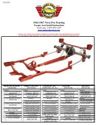
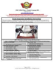
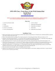
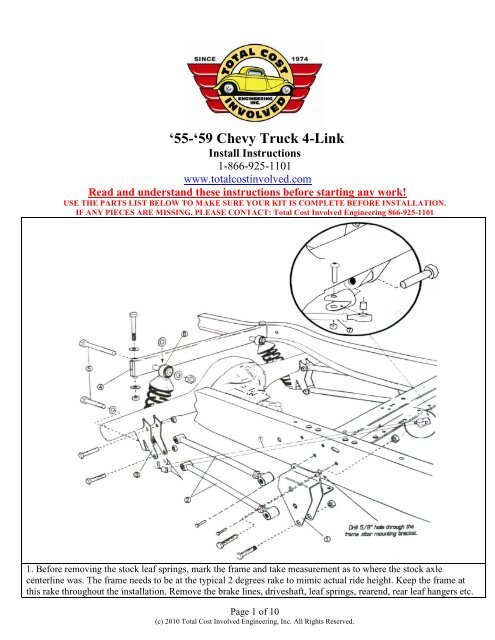
‘55-‘59 Chevy Truck 4-<strong>Link</strong>Install Instructions1-866-925-1101www.totalcostinvolved.comRead and understand these instructions before starting any work!USE THE PARTS LIST BELOW TO MAKE SURE YOUR KIT IS COMPLETE BEFORE INSTALLATION.IF ANY PIECES ARE MISSING, PLEASE CONTACT: <strong>Total</strong> <strong>Cost</strong> <strong>Involved</strong> Engineering 866-925-11011. Before removing the stock leaf springs, mark the frame and take measurement as to where the stock axlecenterline was. The frame needs to be at the typical 2 degrees rake to mimic actual ride height. Keep the frame atthis rake throughout the installation. Remove the brake lines, driveshaft, leaf springs, rearend, rear leaf hangers etc.Page 1 of 10(c) 2010 <strong>Total</strong> <strong>Cost</strong> <strong>Involved</strong> Engineering, Inc. All Rights Reserved.
The new bracket will be using the holes that were justdrilled out on the bottom and two more per side shown inthe picture to the left. Drill out all rivet holes to 7/16”.There are two on the side of the frame and twounderneath (on both passenger & driver sides).Determining left and right side brackets:The lower 4-link bar hole on the frame brackets will befurther forward than the upper holes and the brackets siton the outside of the frame rail.Place the 4-link frame brackets onto the frame where theoriginal front spring perch used to be. Make sure theexisting holes line up and install the 7/16” hardware withthe nuts on the inside of the frame. Torque to 55 ft lbsTorque these 4 bolts to 55 ft lbsLocate the 5/8” upper 4-link bar hole within the newbracket. Using a 5/8” bit, drill through the frame using theexisting 5/8” hole on the bracket as a guide.This will be for the attachment point for the upper linkbar.Page 3 of 10(c) 2010 <strong>Total</strong> <strong>Cost</strong> <strong>Involved</strong> Engineering, Inc. All Rights Reserved.
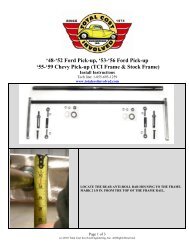
Here is a shot from inside the frame after the 5/8” holehas been drilled.Welding the Axle brackets onto the housing:The factory leaf spring pads must first be removed from the housing and the area cleaned up. The axle brackets areinstalled at 36” Center to center. Make sure that they are centered on the housing. Also, make sure the pinion ispointed up one degree in comparison to the flat area at the backside of the brackets (where the three holes for thecoil-overs are located). Use the 3 rd member mounting face on a Ford 9” or the differential cover on a GM housing asreference.Adjust all the 4-link bars to 24.25” center to center andtighten the jam nuts.*NOTE* It might be necessary to adjust the 4-link barslater to center the tires in the wheel wells.Page 4 of 10(c) 2010 <strong>Total</strong> <strong>Cost</strong> <strong>Involved</strong> Engineering, Inc. All Rights Reserved.
Install the 4-link bars with the adjuster side onto theframe using the provided 5/8” hardware. The bolts go infrom the outside of the frame which will place the nylockon the inboard side.*NOTE* The driver’s side front lower link bar does notuse a nylock nut, rather a clevis for attaching the trackbar. Install the clevis onto this bolt at this time.Torque all 5/8” hardware to 125 ft lbs(the clevis can beleft hand tight for now)Place the lower 4-link bars onto the lower hole of the axlebracket using the provided 5/8” hardware.*NOTE* The passenger side rear lower link bar does notuse a nylock nut, rather a clevis for attaching the trackbar. Install the clevis onto this bolt at this time.Leave bolts & the clevis hand tight for nowPlace the upper 4-link bars onto the upper hole of the axlebracket using the provided 5/8” hardware.*NOTE* If you purchased the optional anti-sway pleaseuse the provided shoulder bolt within the anti-sway barbolt kit. *Pictures of the anti-sway bar installation arelater in this manualLeave bolts loose for nowPage 5 of 10(c) 2010 <strong>Total</strong> <strong>Cost</strong> <strong>Involved</strong> Engineering, Inc. All Rights Reserved.
Install the offset axle brackets onto the axle bracketsusing the provided 5/8” hardware. These are designed tokeep the coil-overs from making contact with the framerail as the suspension compresses. The flat area of theplate will sit parallel to the ground and the shock holewill sit inboard of the bracket when properly installed.*NOTE* You may need to run a 5/8” bit through theholesTorque to 125 ft lbsRemove the factory shock cross member using the sameprocess as before with the leaf spring brackets.Place the new coil-over cross member into the frame railwith the extended tube for the shock mount pointingforward.*NOTE* The new cross member will be positioned intothe same holes that the factory cross member used.Page 6 of 10(c) 2010 <strong>Total</strong> <strong>Cost</strong> <strong>Involved</strong> Engineering, Inc. All Rights Reserved.
Drill out the factory holes with a 1/2” bit. Place the crossmember into place and install the 1/2” hardware.You can now install the coil-overs using the provided5/8” hardware. The threaded side goes down as per thepicture.*NOTE* The springs were left off the shock for thispicture to show the threaded end more clearly. Yourshocks will come preassembled.Torque the 1/2” cross member bolts to 65 ft lbsTorque the 5/8” shock bolts to 125 ft lbsInstall one rod end of the track bar onto either clevis anduse it as leverage to tighten it down. Remove the rod endfrom that clevis and repeat this process on the otherclevis. You may need to rotate the clevis so that the 9/16”bolts holding the rod end are sitting vertical. Install thetrack bar completely onto the clevises. Make sure the rearend is centered in the frame and that the wheel base iscorrect by adjusting the <strong>Link</strong> & Track bars accordingly.Tighten down the jam nuts on the Track and 4-link bars.Torque the 9/16” bolts to 75 ft lbsIf you purchased the optional anti-sway bar proceed to the next step.If not, reinstall the driveshaft, brake lines etc and drop the vehicle down onto its full weight. Adjust ride height asneeded with the coil-over shocks. Double check all hardware and make sure the pinion angle is still one degree up.Adjust the link bars accordingly.Installing the optional Anti-Sway bar:Page 7 of 10(c) 2010 <strong>Total</strong> <strong>Cost</strong> <strong>Involved</strong> Engineering, Inc. All Rights Reserved.
LOCATING THE REAR ANTI-ROLL BAR HOUSING TOTHE FRAME:*NOTE* The pictured frame has been boxedMark the frame 2 1/4” from the rear face of the coilover crossmember.Measure down 2 1/8” down from the top of the rail at the markyou just made. Use a center punch to mark the frame where thesetwo measurements intersect. This is the anti-roll bar housingcenterline.Duplicate the last two steps for the opposite side of the vehicle.Use a 1 ¼” hole saw to drill through the frame at the markedlocation.Place the housing through the frame making sure it protrudes thesame distance on both sides.Once it is centered, it can be welded into place.Page 8 of 10(c) 2010 <strong>Total</strong> <strong>Cost</strong> <strong>Involved</strong> Engineering, Inc. All Rights Reserved.
Place the splined bar into the housing.SEQUENCE OF INSTALLATION PER SIDE:1. Nyliner2. Washer3. Aluminum armDuplicate these steps for the other side of the vehicle making surethe aluminum arms are clocked the same. Tighten down the pinchbolts on the splined end of the bar.*NOTE* Make sure the countersunk side of the aluminum arm isfacing the frame. *SEE BELOWInstall flat head bolt and provided spacer.Install the 3/8” rod ends and extension rod onto the aluminumarm.The lower 3/8” rod end connects to the upper 4-link bolt. This iswhere the special shoulder bolt should be installed. If you haven’tinstalled this bolt already during the 4-link process you will needto remove the upper link bolt and replace it with the providedshoulder bolt. The shoulder side should face out towards thewheel. Install the short 5/8” nylock and then tighten it down. Therod end goes on next and the the 3/8” nylock onto the small end ofshoulder bolt.Duplicate the process for the other side of the vehicle making surethe extension rods are sitting vertical. Adjust the extension rod asneeded to have zero preload.Page 9 of 10(c) 2010 <strong>Total</strong> <strong>Cost</strong> <strong>Involved</strong> Engineering, Inc. All Rights Reserved.
Here is how the finalized installation will look.No returns or exchanges without a RMA#.Packages must be inspected upon receipt & be reported within 10 days.If you are missing parts from your kit, TCI Engineering will send the missing parts via FedEx or U.S. mail ground.Returned packages are subject to inspection before replacement/refund is given.(Some items will be subject to a15% restocking fee)Thank you for your business!Page 10 of 10(c) 2010 <strong>Total</strong> <strong>Cost</strong> <strong>Involved</strong> Engineering, Inc. All Rights Reserved.