Bathroom Fan/Light Combination MODEL: 667RN - NuTone
Bathroom Fan/Light Combination MODEL: 667RN - NuTone
Bathroom Fan/Light Combination MODEL: 667RN - NuTone

You also want an ePaper? Increase the reach of your titles
YUMPU automatically turns print PDFs into web optimized ePapers that Google loves.
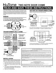
IMPORTANT SAFETY INSTRUCTIONS<br />
WARNING: TO REDUCE THE RISK OF FIRE. ELECTRIC<br />
SHOCK, OR INJURY TO PERSONS, OBSERVE THE<br />
FOLLOWING:<br />
A. Use this unit only in the manner intended by the manufacturer.<br />
If you have questions, contact the manufacturer.<br />
B. Before servicing or cleaning unit, switch power off at service<br />
panel and lock service panel to prevent power from being<br />
switched on accidentally.<br />
When the service disconnecting means cannot be locked, securely<br />
fasten a prominent warning device, such as a tag, to the service panel.<br />
CAUTION:<br />
For general ventilating use only. Do not use to exhaust<br />
hazardous or explosive materials and vapors.<br />
INSTALLATION INSTRUCTIONS<br />
WARNING: TO REDUCE THE RISK OF FIRE, ELECTRIC<br />
SHOCK, OR INJURY TO PERSONS, OBSERVE THE<br />
FOLLOWING:<br />
A. Installation work and electrical wiring must be done by qualified<br />
person(s) in accordance with all applicable codes and standards,<br />
including fire-rated construction.<br />
B. Sufficient air is needed for proper combustion and exhausting of<br />
gases through the flue (chimney) of fuel burning equipment to<br />
prevent back drafting. Follow the heating equipment<br />
manufacturer's guideline and safety standards such as those<br />
published by the National Fire Protection Association<br />
(NFPA),and the American Society for Heating, Refrigeration and<br />
Air Conditioning Engineers (ASHRAE), and the local code<br />
authorities.<br />
C. When cutting or drilling into wall or ceiling, do not damage<br />
electrical wiring and other hidden utilities.<br />
D. Ducted fans must always be vented to the outdoors.<br />
E. If this unit is to be installed over a tub or shower, it must be<br />
marked as appropriate for the application.<br />
F. NEVER place a switch where it can be reached from a tub<br />
or shower.<br />
• U.L. listed “Type IC” for installation in insulated ceilings.<br />
• WARNING: To reduce the risk of fire or electrical shock,<br />
do not use this fan with any solid-state speed control.<br />
• Not for use in kitchens.<br />
• NOTE: Suitable for use over tub or shower when connected<br />
to a GFI protected branch circuit.<br />
• For installation in sloped ceilings up to 12/12 pitch.<br />
• Ductwork must point up.<br />
When installing the <strong>Fan</strong>-<strong>Light</strong> in a new construction site, install the<br />
housing during rough-in construction. <strong>Fan</strong> unit and light assembly<br />
should be installed after the finished ceiling is in place.<br />
To install the <strong>Fan</strong>-<strong>Light</strong> in an existing home, an accessible area<br />
above the proposed installation location (attic or crawl space) is<br />
required. The housing must be installed to a finished ceiling from<br />
above.<br />
LOCATION<br />
The <strong>Fan</strong>-<strong>Light</strong> is intended for installation in a bathroom<br />
or laundry room. Choose a location appropriate for a light.<br />
CAUTION: When installed over a tub or shower,<br />
the unit must be connected to a GFI protected branch circuit.<br />
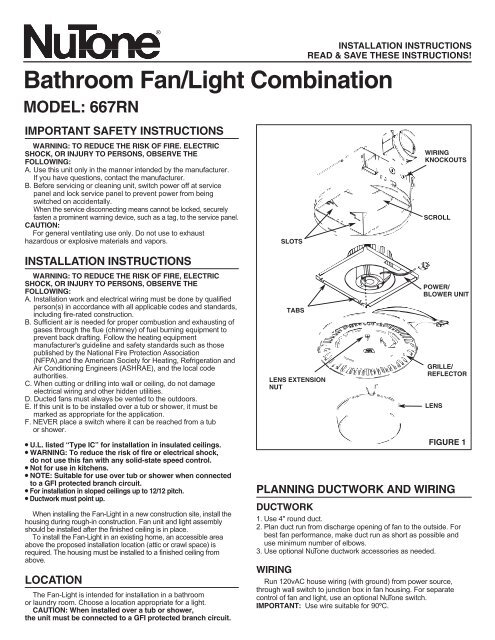
INSTALLATION INSTRUCTIONS<br />
READ & SAVE THESE INSTRUCTIONS!<br />
<strong>Bathroom</strong> <strong>Fan</strong>/<strong>Light</strong> <strong>Combination</strong><br />
<strong>MODEL</strong>: <strong>667RN</strong><br />
SLOTS<br />
TABS<br />
LENS EXTENSION<br />
NUT<br />
WIRING<br />
KNOCKOUTS<br />
SCROLL<br />
POWER/<br />
BLOWER UNIT<br />
GRILLE/<br />
REFLECTOR<br />
LENS<br />
FIGURE 1<br />
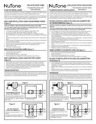
PLANNING DUCTWORK AND WIRING<br />
DUCTWORK<br />
1. Use 4" round duct.<br />
2. Plan duct run from discharge opening of fan to the outside. For<br />
best fan performance, make duct run as short as possible and<br />
use minimum number of elbows.<br />
3. Use optional <strong>NuTone</strong> ductwork accessories as needed.<br />
WIRING<br />
Run 120vAC house wiring (with ground) from power source,<br />
through wall switch to junction box in fan housing. For separate<br />
control of fan and light, use an optional <strong>NuTone</strong> switch.<br />
IMPORTANT: Use wire suitable for 90ºC.
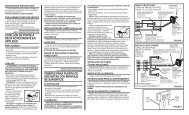
INSTALLATION IN<br />
A NEW CONSTRUCTION SITE<br />
PREPARATION<br />
1. Refer to Figure 1. Remove power unit/blower assembly<br />
from housing.<br />
A. Unplug power unit.<br />
B. Remove screw (located next to plug-in receptacle) which<br />
holds power/blower unit mounting plate in place. Save<br />
this screw.<br />
C. Lift mounting plate at end near the plug-in receptacle until<br />
blower wheel clears the scroll.<br />
D. Remove plate by pulling its tabs out of slots in housing. Set<br />
power/blower unit aside until needed.<br />
2. Remove one of the wiring knockouts from housing.<br />
MOUNTING THE HOUSING<br />
Note: When installing in existing construction, refer to page 3<br />
Mounting Using Mounting Tabs<br />
Refer to Figure 2.<br />
1. Locate fan housing next to ceiling joist.<br />
2. Use wood screws (not provided) to loosely attach housing to<br />
ceiling joist through the keyhole slots in mounting tabs.<br />
3. Adjust housing so that it will be flush with finished ceiling. For the<br />
grille to fit properly, the housing's rim must not extend beyond the<br />
finished ceiling surface.<br />
4. When housing is properly adjusted, tighten screws in slots.<br />
Mounting Using Hanger Bars<br />
(Hanger bars sold separately, order model HB4)<br />
Refer to Figure 3.<br />
1. Insert hanger bars in slots provided in housing.<br />
2. Locate fan housing between joists so that the bottom of the<br />
housing is even with the planned finished ceiling.<br />
3. Use screws or nails (not provided) to secure hanger bars to<br />
ceiling joists.<br />
INSTALLING DUCTWORK<br />
1. Refer to Figure 2. Place duct collar over flanges at discharge<br />
opening of fan. Secure collar by snapping tabs into slots in flanges.<br />
2. Run 4" round duct from fan's discharge opening to the outside and<br />
terminate as illustrated.<br />
3. Connect duct to fan's duct collar.<br />
WIRING<br />
All wiring must comply with local codes and unit must be<br />
properly grounded.<br />
1. Run 120vAC house wiring (with ground) from wall switch<br />
to fan location.<br />
2. Insert and secure an approved box connector into wiring<br />
entrance hole.<br />
3. Pull wires through box connector and into junction box. Tighten<br />
box connector.<br />
4. Refer to Figure 4. If a single switch will be used to control both the<br />
fan and the light, make wiring connections. As shown.<br />
Refer to Figure 5. If a double switch will be used for separate<br />
control of the fan and light, make connections. As shown.<br />
NOTE: If a double switch is used, the wiring connections<br />
determine which receptacle will be used for the fan motor<br />
plug and which receptacle will be used for the light plug.<br />
5. Connect the green (or bare) ground wire to the green ground lead.<br />
POWER/BLOWER INSTALLATION<br />
1. Place power/blower unit into housing so that mounting plate's<br />
tabs insert into slots in housing.<br />
2. Press other end of mounting plate down until it is firmly<br />
seated over scroll and plug-in receptacles.<br />
3. Secure mounting plate to housing with provided screw.<br />
4. Insert motor plug into junction box receptacle.<br />
FLANGES<br />
HANGER BARS<br />
DUCT COLLAR<br />
BOTTOM RIM<br />
BOTTOM RIM<br />
FAN LIGHT FAN<br />
120vAC, 60 Hz<br />
HOUSE POWER<br />
SWITCH<br />
BOX<br />
EARTH<br />
GROUND<br />
HOUSING<br />
FAN LIGHT<br />
WIRING<br />
KNOCKOUTS<br />
MOUNTING<br />
TABS<br />
LIGHT<br />
120vAC, 60 Hz<br />
HOUSE POWER<br />
FIGURE 2<br />
HANGER BARS<br />
(SOLD SEPARATELY)<br />
FIGURE 3<br />
SWITCH<br />
BOX<br />
EARTH<br />
GROUND<br />
FIGURE 4 FIGURE 5
COMPLETING INSTALLATION<br />
1. Insert lamp plug into junction box receptacle and secure<br />
reflector/grille assembly to motor frame with extension nut<br />
provided. Turn extension nut until grille is flush to ceiling.<br />
2. Install lamp (100 watt maximum) into socket.<br />
3. Squeezing the mounting spring of the lens, insert springs<br />
into slots on both sides of reflector.<br />
4. Press lens flush against reflector/grille assembly.<br />
CLEANING AND RELAMPING<br />
1. Pull lens away from reflector/grille assembly.<br />
2. Squeezing the mounting springs together, remove lens<br />
to expose socket for relamping.<br />
3. Use only a mild soap and water solution to clean grille and lens.<br />
Do not use strong, abrasive cleaners.<br />
4. After cleaning or relamping, reinstall reflector/grille assembly<br />
and lens as previously instructed.<br />
INSTALLATION IN<br />
EXISTING CONSTRUCTION<br />
PLANNING<br />
Review “INSTALLATION IN A NEW CONSTRUCTION SITE”<br />
and follow all instructions which apply to your installation.<br />
LOCATION: Locate fan between ceiling joists.<br />
WIRING AND DUCTING: Refer to Figures 4 and 5 for wiring.<br />
Plan ducting and wiring before proceeding with installation.<br />
CAUTION: Check area above planned location to be sure that:<br />
(1) Ducting can be installed or that area is sufficient for<br />
proper venting.<br />
(2) Wiring can be run to the planned location.<br />
(3) No wiring or other obstruction might interfere with installation.<br />
INSTALLATION FROM ACCESSIBLE<br />
AREA ABOVE<br />
1. After determining desired location for fan, drill a small hole in the<br />
ceiling. Place a coat hanger or other still wire up through hole to<br />
help in locating from above.<br />
2. Place fan housing on top of ceiling surface against a ceiling joist<br />
and use the housing as a template to mark area to be cut out.<br />
3. After cutting out opening, mount housing in the opening.<br />
A. Position housing in opening so that bottom of housing is<br />
flush with ceiling.<br />
B. Use screws or nails (not provided) to secure housing<br />
to ceiling joists.<br />
4. Install ducting and wiring as described above.<br />
INSTALLATION FROM AREA BELOW CEILING<br />
NOTE: If you do not have access to the area above to installation<br />
location, make sure that the installation will not interfere with existing<br />
wiring, plumbing, etc. and that wiring and ducting can be run to the<br />
desired location. It will be necessary to use flexible duct when<br />
installing the unit from below.<br />
4" FLEXIBLE<br />
DUCT<br />
MOUNTING<br />
HOLES<br />
11 1 ⁄2"<br />
9 1 ⁄8" - 10"<br />
JOIST<br />
5 3 ⁄4"<br />
2"<br />
4"<br />
FIGURE 6<br />
120vAC HOUSE<br />
WIRING<br />
DUCT COLLAR<br />
WIRING<br />
KNOCKOUT<br />
BEND MOUNTING<br />
TABS FLUSH TO<br />
SIDE OF HOUSING<br />
FIGURE 7
INSTALLATION<br />
1. The fan must be mounted between ceiling joists. Decide where you want to locate the fan, and then<br />
determine where the nearest joists are.<br />
LOCATING JOISTS: <strong>Light</strong>ly tap the ceiling. A hollow sound means no joist; a solid sound means a<br />
joist is present. To be sure you have located a joist, drill a small hole ( 1 ⁄16") and probe into the ceiling<br />
with a wire.<br />
2. Locate the joists. Drill a starter hole in the ceiling between<br />
the joists.<br />
3. To exactly locate edge of joist, saw a line from hole to joist.<br />
4. Remove power/blower unit from housing (see page 2.)<br />
5. Use the housing pan as a template to mark cutout: place pan centered between joist and trace<br />
around pan.<br />
6. Make cutout along outside of marked line.<br />
7. Refer to Figure 6. Install 2 x 4 cleats to both ceiling joists.<br />
In some cases it may be necessary to use more than a single cleat on one side. The distance<br />
between cleats must be<br />
at least 9 1 ⁄8" but no more than 10".<br />
8. Remove side wiring knockout. Insert and secure an approved box connector into the wiring<br />
entrance hole.<br />
9. Use pliers to bend both mounting tabs as flush as possible<br />
to the side of the housing.<br />
10. Install duct collar.<br />
11. Refer to Figure 7. String wiring through box connector<br />
and connect 4" flexible duct to duct collar.<br />
12. Carefully push ductwork and wiring back into cutout. Place housing into cutout.<br />
13. Use wood screws to secure housing to cleats through four holes in housing's pan. Make sure pan<br />
is flush to finished ceiling.<br />
14. Install power/blower unit and complete installation as described above.<br />
One Year Limited Warranty<br />
WARRANTY OWNER: <strong>NuTone</strong> warrants to the original consumer purchaser of its products that such products will be free from defects in materials or workmanship for a period<br />
of one (1) year from the date of original purchase. THERE ARE NO OTHER WARRANTIES, EXPRESS OR IMPLIED, INCLUDING, BUT NOT LIMITED TO, IMPLIED<br />
WARRANTIES OF MERCHANTABILITY OR FITNESS FOR A PARTICULAR PURPOSE.<br />
During this one year period, <strong>NuTone</strong> will, at its option, repair or replace, without charge, any product or part which is found to be defective under normal use and service.<br />
THIS WARRANTY DOES NOT EXTEND TO FLUORESCENT LAMP STARTERS OR TUBES, FILTERS, DUCT, ROOF CAPS, WALL CAPS AND OTHER ACCESSORIES<br />
FOR DUCTING. This warranty does not cover (a) normal maintenance and service or (b) any products or parts which have been subject to misuse, negligence, accident,<br />
improper maintenance or repair (other than by <strong>NuTone</strong>), faulty installation or installation contrary to recommended installation instructions.<br />
The duration of any implied warranty is limited to the one year period as specified for the express warranty. Some states do not allow limitation on how long an implied warranty<br />
lasts, so the above limitation may not apply to you.<br />
NUTONE’S OBLIGATION TO REPAIR OR REPLACE, AT NUTONE’S OPTION, SHALL BE THE PURCHASER’S SOLE AND EXCLUSIVE REMEDY UNDER THIS<br />
WARRANTY. NUTONE SHALL NOT BE LIABLE FOR INCIDENTAL, CONSEQUENTIAL OR SPECIAL DAMAGES ARISING OUT OF OR IN CONNECTION WITH<br />
PRODUCT USE OR PERFORMANCE. Some states do not allow the exclusion or limitation of incidental or consequential damages, so the above limitation or exclusion may<br />
not apply to you. This warranty gives you specific legal rights, and you may also have other rights, which vary from state to state. This warranty supersedes all prior warranties.<br />
WARRANTY SERVICE: To qualify for warranty service, you must (a) notify <strong>NuTone</strong> at the address stated below or telephone 1/800-543-8687, (b) give the model<br />
number and part identification and (c) describe the nature of any defect in the product or part. At the time of requesting warranty service, you must present<br />
evidence of the original purchase date.<br />
Date of Installation Builder or Installer<br />
Model No. and Product Description<br />
IF YOU NEED ASSISTANCE OR SERVICE:<br />
For the location of your nearest <strong>NuTone</strong> Independent Authorized Service Center:<br />
Residents of the contiguous United States Dial Free 1-800-543-8687<br />
Please be prepared to provide:<br />
Product model number • Date and Proof of purchase • The nature of the difficulty<br />
Residents of Alaska or Hawaii should write to: <strong>NuTone</strong> Inc. Attn: Department of National Field Service, 4820 Red Bank Road, Cincinnati Ohio 45227-1599.<br />
Residents of Canada should write to: Broan-<strong>NuTone</strong> Canada, 1140 Tristar Drive, Mississauga, Ontario, Canada L5T 1H9.<br />
Rev. 03/2001<br />
Product specifications subject to change without notice.<br />
4820 Red Bank Road, Cincinnati, Ohio 45227<br />
Printed in U.S.A., Rev. 4/2003, Part No. 87574
PARTS LIST<br />
3<br />
2<br />
1<br />
9<br />
6<br />
10<br />
EFFECTIVE<br />
DATE<br />
Revised<br />
APRIL<br />
2003<br />
<strong>MODEL</strong> NUMBER<br />
<strong>667RN</strong><br />
PRODUCT<br />
GROUP<br />
REF.<br />
ORIGINAL<br />
PART NO.<br />
*PART DESCRIPTION <strong>MODEL</strong> USED ON<br />
CURRENT<br />
REPLACEMENT<br />
PART NO.<br />
1 0685B POWER UNIT ASSEMBLY <strong>667RN</strong> 0685B-000<br />
2 86677 MOTOR <strong>667RN</strong> 86677-000<br />
3 89914 BLOWER WHEEL <strong>667RN</strong> 89914-000<br />
4 86308 REFLECTOR ASSEMBLY <strong>667RN</strong> 86308-000<br />
5 85979 LAMPSOCKET <strong>667RN</strong> 85979-000<br />
6 30652 DUCT ADAPTER ASSEMBLY <strong>667RN</strong> 30652-000<br />
7 86312 RETAINING RING/LENS/SPRING ASSY <strong>667RN</strong> 86312-000<br />
8 16133 WING NUT <strong>667RN</strong> 16133-000<br />
9 10034 FAN RECEPTACLE <strong>667RN</strong> 10034-000<br />
10 82304 LIGHT RECEPTACLE <strong>667RN</strong> 82304-000<br />
11 85943 LENS ONLY <strong>667RN</strong> 85943-000<br />
12 57889 RETAINING RING <strong>667RN</strong> 57889-206<br />
13 36919 REFLECTOR <strong>667RN</strong> 36919-206<br />
<strong>NuTone</strong><br />
Attn: Parts Department<br />
4820 Red Bank Road<br />
Cincinnati, OH 45227-1599<br />
148<br />
58<br />
9<br />
11 7<br />
13<br />
12 12<br />
FAN<br />
NOTE: Always order by<br />
current part number<br />
<strong>667RN</strong> I.I.<br />
13<br />
11<br />
4