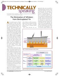
IPC 2009thickness and <strong>for</strong>med wirings of 0.05, 0.1, 0.5, and 1.0 mmin width on them by etching. We used these substrates <strong>for</strong>bending tests and MIT tests. For plating, we usedcommercially available plating chemicals from C. Uemura& Co., Ltd.. Table-1 shows this plating process. We used theNPG-1 from this company <strong>for</strong> a bath <strong>for</strong>ming coating thatbreaks into columnar shapes (herein after referred to as the“ductility-compatible bath) to make comparisons <strong>with</strong> a bath<strong>for</strong>ming coating that breaks into layer shapes (hereinafterreferred to as the “conventional bath”).Table-1. Ni-P/Au plating processProcess Chemical Temp. Time.Cleaner ACL-839 40 deg.C 5 min.rinceSoft etching SPS type 25 deg.C 1 min.rinceAcid rinse 10% H 2 SO 4 r.t. 1 min.rincePre-dipping 3% H 2 SO 4 r.t. 1 min.Activator MNK-4 30 deg.C 2 min.rince<strong>Electroless</strong> Ni (C) Conventional 80 deg.C *<strong>Electroless</strong> Ni (N) NPG-1 82 deg.C *rince<strong>Electroless</strong> Au TAM-LC 80 deg.C 10 min.* : Different thickness was made by changed the dipping time.We verified all assessments by changing the nickel coatingthickness and adjusted the nickel coating thickness bychanging plating time.We standardized the gold plating thickness to 0.05m.3. Precipitated ShapesWe plated the flexible substrates in the two types of baths;the conventional and ductility-compatible bath so that Ni/Aucoating thickness will come to 5/0.05m, cut the substratesphysically using a cutter, and then observed theircross-section using a SEM.As shown in Fig.-1, the results indicate that theconventional bath <strong>for</strong>ms coating that breaks into layer shapes,while the ductility-compatible bath <strong>for</strong>ms coating that breaksinto columnar shapes. We considered that the results wererelated to the properties of elctroless nickel coating, andconsequently conducted a variety of ductility testsConventionalNPG-1CuCuNiNiFig.-1 SEM photographs of cross-section of electrolessnickel coatingTop: Conventional bath, Bottom: Ductility-compatiblebath4. Bending Tests and MIT TestsWe conducted bending tests on flexible substrates afterplating using wiring of 1 mm in width. To make comparison,we plated the flexible substrates <strong>with</strong> nickel to coatingthickness of 2 and 5μm in the two types of nickel platingbaths; the conventional and ductility-compatible baths. Forbending tests, we wound the flexible substrate around astainless steel rod of 1 mm in diameter in accordance <strong>with</strong>ISO 7438 and made assessments.As shown in Table-2, the test results indicate that theflexible substrate plated in the conventional bath to 2-μmthickness did not break but substrate plated in the same to5-μm thickness caused cracks, and that the flexible substratesplated in the ductility-compatible bath to 2-μm and 5-μmthickness caused no cracks.On the other hand, <strong>for</strong> MIT tests, we used the sameflexible substrates as those <strong>for</strong> the bending tests and madeassessments using wiring of 0.5 mm in width. We plated thesubstrates <strong>with</strong> nickel to thickness of 1, 2, 3, 4, 5, and 6μm,respectively, and conducted the MIT tests in accordance <strong>with</strong>ASTM D2176. Table-3 summarizes the MIT test method.As shown in Fig.-2, the test results indicate that thesubstrates plated in the conventional bath showed reductionin the number of cycles conducted until they caused brokenwires as the coating thickness became thicker, but thesubstrates plated in the ductility-compatible bath showed noreduction in the number of cycles until they caused broken2/5
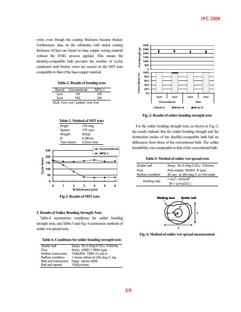
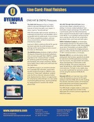
IPC 2009wires even though the coating thickness became thicker.Furthermore, data on the substrates <strong>with</strong> nickel coatingthickness of 0μm are based on base copper wiring material<strong>with</strong>out the <strong>ENIG</strong> process applied. This means theductility-compatible bath provides the number of cyclesconducted until broken wires are caused on the MIT testscompatible to that of the base copper material.Table-2. Results of bending testsResult Conventional NPG-12m OK OK5m NG OKSUS 1mm rod / plated 1mm lineFailure Mode (%) Pull Strength (g)300025002000150010005000100%80%60%40%20%0%2um 5um 2um 5umConventionalNewMode A Mode B Mode DCycle times250200150100500Table-3. Method of MIT testsAngleSpeedWeightRTest board135 deg.175 cpm500gf0.38mm0.5mm lineConventionalNPG-10 1 2 3 4 5 6Ni thickness [um]Fig-2. Results of MIT testsFig.-3. Results of solder bonding strength testsFor the solder bonding strength tests, as shown in Fig.-3,the results indicate that the solder bonding strength and thedestruction modes of the ductility-compatible bath had nodifferences from those of the conventional bath. The solderbondability was comparable to that of the conventional bath.Solder ballTable-5. Method of solder wet spread testsFluxReflow conditionWetting rateSenju Sn-3.0Ag-0.5Cu 0.6mmArfa metals R5003 R type45 sec. at 260 deg.C on Hot plate= 4r 2 / (4/3)R 3[R = (a+b)/2/2 ]Wetting areaSolder ball5. Results of Solder Bonding Strength TestsTable-4 summarizes conditions <strong>for</strong> solder bondingstrength tests, and Table-5 and Fig.-4 summarize methods ofsolder wet spread tests.Table-4. Conditions <strong>for</strong> solder bonding strength testsSolder ball Senju Sn-3.0Ag-0.5Cu 0.6mmFluxSenju 529D-1 RMA typeReflow instrument TAMURA TMR-15-22LHReflow condition 1 times reflow at 240 deg.C top.Ball pull instrument Dage series 4000Ball pull speed 1000m/secRarbFig.-4. Method of solder wet spread measurement3/5