Geovision Fisheye IP Camera User Manual - Use-IP
Geovision Fisheye IP Camera User Manual - Use-IP
Geovision Fisheye IP Camera User Manual - Use-IP

Create successful ePaper yourself
Turn your PDF publications into a flip-book with our unique Google optimized e-Paper software.
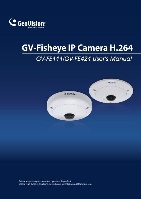
GV-<strong>Fisheye</strong> <strong>IP</strong> <strong>Camera</strong> H.264<br />
GV-FE111/GV-FE421 <strong><strong>Use</strong>r</strong>'s <strong>Manual</strong><br />
Before attempting to connect or operate this product,<br />
please read these instructions carefully and save this manual for future use.
© 2010 GeoVision, Inc. All rights reserved.<br />
Under the copyright laws, this manual may not be copied, in whole or in part,<br />
without the written consent of GeoVision.<br />
Every effort has been made to ensure that the information in this manual is<br />
accurate. GeoVision, Inc. makes no expressed or implied warranty of any kind<br />
and assumes no responsibility for errors or omissions. No liability is assumed<br />
for incidental or consequential damages arising from the use of the information<br />
or products contained herein. Features and specifications are subject to<br />
change without notice.<br />
GeoVision, Inc.<br />
9F, No. 246, Sec. 1, Neihu Rd.,<br />
Neihu District, Taipei, Taiwan<br />
Tel: +886-2-8797-8377<br />
Fax: +886-2-8797-8335<br />
http://www.geovision.com.tw<br />
Trademarks used in this manual: GeoVision, the GeoVision logo and GV<br />
series products are trademarks of GeoVision, Inc. Windows and Windows XP<br />
are registered trademarks of Microsoft Corporation.<br />
December 2010
Preface<br />
Welcome to the GV-<strong>Fisheye</strong> <strong>IP</strong> <strong>Camera</strong> <strong><strong>Use</strong>r</strong>’s <strong>Manual</strong>.<br />
The GV-<strong>Fisheye</strong> <strong>IP</strong> <strong>Camera</strong> has two models with different resolutions. This <strong>Manual</strong> is<br />
designed for the following models and firmware versions:<br />
Model Model Number Firmware Version<br />
<strong>Fisheye</strong> <strong>Camera</strong><br />
GV-FE111<br />
GV-FE421<br />
V1.06<br />
V1.01<br />
i
Contents<br />
Naming and Definition .............................................................1<br />
Note for Recording...................................................................2<br />
Note for Firmware Upgrade .....................................................3<br />
1.1 Key Features ............................................................................................................4<br />
1.2 Packing List ..............................................................................................................5<br />
1.3 System Requirement ................................................................................................6<br />
1.4 Options .....................................................................................................................6<br />
1.5 Physical Description .................................................................................................7<br />
1.6 Lens Adjustment.......................................................................................................8<br />
1.7 Installation ................................................................................................................9<br />
1.7.1 Hard Ceiling Mount ......................................................................................9<br />
1.7.2 In-Ceiling Mount .........................................................................................10<br />
1.7.3 Wall Mount and Ground Mount ..................................................................12<br />
1.8 Connecting the Data Cable ....................................................................................13<br />
Chapter 2 Getting Started ...................................................15<br />
2.1 Installing on a Network ...........................................................................................15<br />
2.2 Assigning an <strong>IP</strong> Address ........................................................................................15<br />
2.3 Configuration Basics...............................................................................................17<br />
Chapter 3 Accessing the <strong>Camera</strong>.......................................18<br />
ii<br />
3.1 Accessing Your Surveillance Images .....................................................................18<br />
3.2 Functions Featured on the Main Page ...................................................................19<br />
3.2.1 The Live View Window...............................................................................20<br />
3.2.2 <strong>Fisheye</strong> View..............................................................................................22<br />
3.2.3 The Control Panel of the Live View Window ..............................................26<br />
3.2.3 The Control Panel of the Live View Window ..............................................26<br />
3.2.4 Snapshot of a Live Video ...........................................................................29<br />
3.2.5 Video Recording.........................................................................................30<br />
3.2.6 Picture-in-Picture and Picture-and-Picture View ........................................30<br />
3.2.7 Alarm Notification .......................................................................................33<br />
3.2.8 Video and Audio Configuration ..................................................................34
3.2.9 Remote Configuration ................................................................................34<br />
3.2.10 <strong>Camera</strong> Name Display .............................................................................35<br />
3.2.11 Image Enhancement ................................................................................35<br />
3.2.12 I/O Control................................................................................................36<br />
3.2.13 Visual Automation ....................................................................................37<br />
3.2.14 Network Status.........................................................................................37<br />
Chapter 4 Administrator Mode ...........................................38<br />
4.1 Video & Motion .......................................................................................................40<br />
4.1.1 Video Settings ............................................................................................40<br />
4.1.2 Motion Detection ........................................................................................43<br />
4.1.3 Privacy Mask..............................................................................................44<br />
4.1.4 Tampering Alarm........................................................................................45<br />
4.1.5 Visual Automation ......................................................................................47<br />
4.2 I/O Control ..............................................................................................................48<br />
4.2.1 Input Settings .............................................................................................48<br />
4.2.2 Output Settings ..........................................................................................49<br />
4.3 Events & Alerts.......................................................................................................50<br />
4.3.1 E-mail .........................................................................................................50<br />
4.3.2 FTP ............................................................................................................52<br />
4.3.3 Center V2 ...................................................................................................54<br />
4.3.4 VSM ...........................................................................................................56<br />
4.3.5 ViewLog Server..........................................................................................58<br />
4.3.6 RTSP..........................................................................................................59<br />
4.4 Monitoring...............................................................................................................60<br />
4.5 Recording Schedule ...............................................................................................61<br />
4.5.1 Recording Schedule Settings.....................................................................61<br />
4.5.2 I/O Monitoring Settings...............................................................................62<br />
4.6 Remote ViewLog ....................................................................................................63<br />
4.7 Network ..................................................................................................................64<br />
4.7.1 LAN ............................................................................................................64<br />
4.7.2 Advanced TCP/<strong>IP</strong>.......................................................................................66<br />
4.7.3 <strong>IP</strong> Filtering ..................................................................................................69<br />
4.7.4 SNMP Setting.............................................................................................70<br />
4.8 Management...........................................................................................................71<br />
4.8.1 Date and Time Settings..............................................................................71<br />
4.8.2 GPS Maps Settings....................................................................................73<br />
4.8.3 Storage Settings.........................................................................................75<br />
iii
4.8.4 <strong><strong>Use</strong>r</strong> Account..............................................................................................77<br />
4.8.5 Log Information ..........................................................................................78<br />
4.8.6 Tools ..........................................................................................................79<br />
Chapter 5 Recording and Playback ...................................80<br />
5.1 Recording ...............................................................................................................80<br />
5.2 Playback.................................................................................................................80<br />
5.2.1 Playback Using the Memory Card..............................................................81<br />
5.2.2 Playback over Network ..............................................................................82<br />
5.2.3 Access to the Recorded Files through FTP Server....................................83<br />
5.2.4 Playback of Daylight Saving Time Events..................................................84<br />
Chapter 6 Advanced Applications .....................................85<br />
6.1 Upgrading System Firmware ..................................................................................85<br />
6.1.1 Using the Web Interface.............................................................................86<br />
6.1.2 Using the <strong>IP</strong> Device Utility..........................................................................87<br />
6.2 Backing Up and Restoring Settings........................................................................89<br />
6.2.1 Backing Up the Settings.............................................................................89<br />
6.2.2 Restoring the Settings................................................................................90<br />
6.3 Restoring to Factory Default Settings.....................................................................91<br />
6.4 Verifying Watermark ...............................................................................................92<br />
6.4.1 Accessing AVI Files ...................................................................................92<br />
6.4.2 Running Watermark Proof..........................................................................92<br />
6.4.3 The Watermark Proof Window ...................................................................93<br />
Chapter 7 DVR Configurations ...........................................94<br />
iv<br />
7.1 Setting Up <strong>IP</strong> <strong>Camera</strong>s...........................................................................................95<br />
7.1.1 Previewing Video and Setting Audio ..........................................................97<br />
7.2 Remote Monitoring with Multi View ........................................................................99<br />
7.2.1 Connecting to the <strong>IP</strong> <strong>Camera</strong>.....................................................................99<br />
7.3 Remote Monitoring with E-Map ............................................................................100<br />
7.3.1 Creating an E-Map for the <strong>IP</strong> <strong>Camera</strong>......................................................100<br />
7.3.2 Connecting to the <strong>IP</strong> <strong>Camera</strong>...................................................................101
Chapter 8 CMS Configurations.........................................102<br />
8.1 Center V2 .............................................................................................................102<br />
8.2 VSM......................................................................................................................104<br />
8.3 Dispatch Server ....................................................................................................105<br />
Specifications .......................................................................106<br />
<strong>Camera</strong> .........................................................................................................................106<br />
Optics Lens ...................................................................................................................106<br />
Operation ......................................................................................................................107<br />
Network.........................................................................................................................107<br />
Mechanical....................................................................................................................108<br />
General .........................................................................................................................108<br />
Power over Ethernet .....................................................................................................108<br />
Web Interface................................................................................................................109<br />
Application.....................................................................................................................109<br />
Appendix ...............................................................................110<br />
A. Settings for Internet Explore 8 ..................................................................................110<br />
B. RTSP Protocol Support ............................................................................................111<br />
v
Naming and Definition<br />
1<br />
Introduction<br />
GV-System GeoVision Analog and Digital Video Recording Software. The GV-<br />
System also refers to Multicam System, GV-NVR System, GV-<br />
Hybrid DVR System and GV-DVR System at the same time.<br />
1
Note for Recording<br />
The GV-<strong>Fisheye</strong> <strong>IP</strong> <strong>Camera</strong> is designed to work with GV-System, a hybrid or digital video<br />
management system. Normally, the images are recorded to the memory card inserted in the<br />
camera. Once the camera is connected to GV-System for video management or its Live<br />
View (Figure 3-3) is accessed through the Web browser, recording to the memory card will<br />
be stopped and GV-System will take over the recording. When the connection between the<br />
camera and GV-System is interrupted, the recording to the memory card will be resumed to<br />
back up the images on the camera.<br />
When connecting from the GV-System, GV-FE421 is only supported on 64-bit operating<br />
systems.<br />
2
Note for Firmware Upgrade<br />
Before you upgrade the firmware, please follow these instructions:<br />
1. The firmware upgrade must be performed on the LAN.<br />
2. Stop monitoring of the camera.<br />
3. Stop all the remote connections including Center V2, VSM and ViewLog Server.<br />
4. Stop the connection to GV-System.<br />
1<br />
Introduction<br />
Failure to follow the above instructions may cause damages to the camera. For details on<br />
firmware upgrade, see 6.1 Upgrading System Firmware in the <strong><strong>Use</strong>r</strong>’s <strong>Manual</strong>.<br />
If firmware upgrade fails, you will need to restore the camera to the default settings. For<br />
details, see 6.3 Restoring to Factory Default Settings in the <strong><strong>Use</strong>r</strong>’s <strong>Manual</strong>.<br />
3
Chapter 1 Introduction<br />
The GV-FE111/GV-FE421 is a fisheye camera that allows you to monitor all angles of a<br />
location using just one camera. The distorted hemispherical image of the fisheye camera will<br />
be converted into the conventional rectilinear projection.<br />
Without installing any software, you can watch live view and utilize functions such as motion<br />
detection, privacy mask, and alert notification through the Web interface using an IE browser.<br />
In addition, the GV-<strong>Fisheye</strong> <strong>IP</strong> <strong>Camera</strong> seamlessly integrates with the GV-System, providing<br />
advanced monitoring and video management features.<br />
1.1 Key Features<br />
• 360 degree fisheye view<br />
• 1/3” progressive scan CMOS for GV-FE111 and 1/2.5” progressive scan CMOS for GV-<br />
FE421<br />
• Built-in Web server for monitoring through IE browser<br />
• Different angle of view controllable by multiple users at the same time<br />
• H.264, MPEG4 and MJPEG video compression for GV-FE111 and H.264 and MJPEG<br />
video compression for GV-FE421<br />
• Up to 15 frames per second at 1280 x 1024 for GV-FE111 and 2048 x 1944 for GV-<br />
FE421<br />
• Built-in microphone and speaker<br />
• Motion detection triggering actions, e.g. image upload and output trigger<br />
• Privacy mask to cover parts of the image that should not be viewable.<br />
• <strong>IP</strong> address filtering<br />
• PoE (Power over Ethernet)<br />
• 16 languages on web interface<br />
4
1.2 Packing List<br />
• <strong>Camera</strong> Body<br />
• <strong>Camera</strong> Cover (Hard Ceiling Mount)<br />
• Screw (Hard Ceiling Mount) x 3<br />
• Security Torx<br />
• 3-Pin Terminal Block<br />
• GV-FE421 Software DVD<br />
• GV-NVR Software DVD<br />
• Support Bracket x 3<br />
• <strong>Camera</strong> Cover (In-Ceiling Mount)<br />
• Screw (In-Ceiling Mount) x 3<br />
• Plastic Screw Anchor x 3<br />
• DC 12V Power Adapter<br />
• Installation Sticker<br />
• GV-NVR Quick Start Guide<br />
1<br />
Introduction<br />
5
1.3 System Requirement<br />
To operate the camera through a web browser, make sure your PC has good network<br />
connection, and meet this system requirement:<br />
• Microsoft Internet Explorer 7.x or later<br />
Note: If you are using Microsoft Internet Explorer 8.0, additional settings are required.<br />
Please refer to Settings for Internet Explorer 8 in Appendix A.<br />
1.4 Options<br />
Optional devices can expand your camera’s capabilities and versatility. Contact your dealer<br />
for more information.<br />
6<br />
GV-PA191<br />
The GV-PA191 is a Power over Ethernet (PoE) adapter designed to<br />
provide power to the <strong>IP</strong> device through a single Ethernet cable.
1.5 Physical Description<br />
1<br />
Introduction<br />
To access the Default button, LED indicators and micro SD card slot, unscrew the three<br />
screws indicated below and then remove the outer shell of the camera.<br />
Figure 1-1<br />
You can now access the Default button, LED indicators, and the micro SD card slot.<br />
No. Name Function<br />
5<br />
6<br />
7<br />
8<br />
Figure 1-2<br />
1 Lens Rotates the lens to adjust focus.<br />
2 Speaker Talks to the surveillance area from the local computer.<br />
3 Microphone Receives the sound from the camera.<br />
4 Default Button<br />
Resets all configurations to default factory settings. See 6.3<br />
Restoring to Factory Default Settings.<br />
5 Micro SD Card Slot Inserts a micro SD/SDHC memory card to store recorded data.<br />
6 Network status LED Indicates the network status.<br />
7 Power status LED Indicates whether the camera is powered on or off.<br />
8 System status LED Indicates whether the system is booted successfully or not.<br />
1<br />
2<br />
3<br />
4<br />
7
1.6 Lens Adjustment<br />
By default, the lens should already be adjusted to produce clear image. If not, you can adjust<br />
the focus by removing the outer shell of the camera and then rotating the lens (No.1, Figure<br />
1-2). To see how to remove the outer shell of the camera, refer to 1.5 Physical Description.<br />
Set an object about 50 cm (19.7 in) in front of the camera and rotate the lens until the image<br />
becomes clear. You can access the live images of the camera by connecting to its Web<br />
interface. Refer to Chapter 2 to see how to install the camera on the network and refer to<br />
Chapter 3 to see how to access the Web interface.<br />
8
1.7 Installation<br />
1<br />
Introduction<br />
The GV-FE111/GV-FE421 is designed to be mounted on the ceiling, wall or ground. There<br />
are two ways to mount the camera on the ceiling, Hard Ceiling Mount and In-Ceiling<br />
Mount. Make sure the ceiling has enough strength to support the fisheye camera.<br />
Hard Ceiling Mount In-Ceiling Mount<br />
Wall Mount Ground Mount<br />
Note: The fisheye camera is designed for indoor use only.<br />
1.7.1 Hard Ceiling Mount<br />
1. Place the installation sticker on the ceiling board. The 3 red dots indicate the location of<br />
the screws.<br />
Figure 1-5<br />
9
2. At the 3 red dots, drill a hole slightly smaller than the plastic screw anchors provided.<br />
3. Insert the 3 plastic screw anchors in the drilled holes.<br />
4. Secure the fisheye camera with the 3 hard ceiling mount screws provided.<br />
10<br />
Figure 1-6<br />
5. Place the camera cover for hard ceiling mount on top of the camera and tighten the<br />
screws with the security torx provided.<br />
Figure 1-7<br />
1.7.2 In-Ceiling Mount<br />
In-Ceiling Mount allows the camera to be mounted into the ceiling, revealing a small portion<br />
of the camera. In-Ceiling Mount requires the ceiling board to be between 0.5 – 3.0 cm (0.2 –<br />
1.18 in) thick.<br />
1. Place the installation sticker on the ceiling board, and cut the circle part out of the ceiling.<br />
Figure 1-8
Introduction<br />
2. Align the 3 support brackets with the holes on the back of the camera as shown below<br />
and secure using the in-ceiling mount screws provided.<br />
Figure 1-9<br />
3. Place the fisheye camera into the ceiling opening as shown below.<br />
Figure 1-10<br />
4. On the back side, make sure the black plastic clips are slightly above the ceiling board<br />
and pointing outward.<br />
Figure 1-11<br />
1<br />
11
5. From the front side of the camera, tighten the screws.<br />
12<br />
Figure 1-12<br />
6. Place the camera cover for in-ceiling mount on top of the camera and tighten the 3<br />
screws.<br />
Figure 1-13<br />
1.7.3 Wall Mount and Ground Mount<br />
To mount the camera on a wall, follow the instructions in Hard Ceiling Mount. For ground<br />
mount, simply place the camera on a flat surface such as a conference table.<br />
Hint: Mount the fisheye camera in the middle of the wall to have an excellent overview. Or<br />
ensure the camera is focused on the most important areas of the room as directly as<br />
possible to have the desired detailed recognition.
1.8 Connecting the Data Cable<br />
1<br />
Introduction<br />
The fisheye camera comes with a 5-pin data cable that allows you to connect to the power<br />
and any I/O devices.<br />
Wire Definition<br />
Figure 1-14<br />
No. Wire Color Definition<br />
1 Yellow AC 24V+ / DC 12V+<br />
2 Orange AC 24V- / DC 12V-<br />
3 Brown Digital Input<br />
4 Red Digital Output<br />
5 Black GND<br />
13
Connecting to Power<br />
You can connect to power using either the power adapter provided or a Power over Ethernet<br />
(PoE) adapter. See “Power over Ethernet” in Specifications later in this manual before<br />
purchasing a PoE adapter. To connect to power using the power adapter, follow the steps<br />
below to connect the orange and yellow wires of the camera to the 3-pin terminal block<br />
provided.<br />
1. Insert the yellow wire to the pin on the right-side of the terminal block and the orange<br />
wire to the pin on the left-side of the terminal block.<br />
2. <strong>Use</strong> a small flat-tip screwdriver to secure the screws above the pins.<br />
14<br />
Figure 1-15<br />
3. Connect the DC 12V Power Adapter to the 3-Pin Terminal Block.<br />
Figure 1-16<br />
Note:<br />
1. A DC 12V power adapter has been provided, but both AC 24V power adapter and DC<br />
12V power adapter are compatible.<br />
2. The power status LED will not visible unless the outer shell of the camera body is<br />
removed.
Chapter 2 Getting Started<br />
This section provides basic information to get the camera working on the network.<br />
2.1 Installing on a Network<br />
2<br />
Getting Started<br />
These instructions describe the basic connections to install the camera on the network.<br />
1. Using a standard network cable, connect the camera to your network.<br />
2. Connect power using one of the methods:<br />
• Using the supplied power adapter, connect to power. For details, see 1.7<br />
Connecting the Data Cable.<br />
• <strong>Use</strong> the Power over Ethernet (PoE) function. The power will be provided over the<br />
network cable.<br />
3. Set the <strong>IP</strong> address for the unit.<br />
Note: See “Power over Ethernet” in Specifications later in this manual before purchasing a<br />
PoE adapter.<br />
2.2 Assigning an <strong>IP</strong> Address<br />
Designed for use on the network, the camera must be assigned an <strong>IP</strong> address to make it<br />
accessible.<br />
Note: The camera has a default <strong>IP</strong> address of 192.168.0.10. The computer used to set<br />
the <strong>IP</strong> address must be under the same network assigned to the unit.<br />
15
1. Open your web browser, and type the default <strong>IP</strong> address http://192.168.0.10<br />
2. In both Login and Password fields, type the default value admin. Click Apply.<br />
3. In the left menu, select Network and then LAN to begin the network settings.<br />
Figure 2-2<br />
4. Select Static <strong>IP</strong> address. Type <strong>IP</strong> Address, Subnet Mask, Router/Gateway, Primary DNS<br />
and Secondary DNS in the Configure connection parameters section.<br />
5. Click Apply. The camera is now accessible by entering the assigned <strong>IP</strong> address on the<br />
16<br />
web browser.<br />
IMPORTANT:<br />
• Dynamic <strong>IP</strong> Address and PPPoE should only be enabled if you know which <strong>IP</strong><br />
address the camera will get from the DHCP server or ISP. Otherwise, you must<br />
use the Dynamic DNS service to obtain a domain name linked to the camera’s<br />
changing <strong>IP</strong> address first.<br />
For details on Dynamic DNS Server settings, see 4.7.2 Advanced TCP/<strong>IP</strong>.<br />
• If Dynamic <strong>IP</strong> Address and PPPoE is enabled and you cannot access the unit,<br />
you may have to reset it to the factory default settings and then perform the<br />
network settings again.<br />
To restore the factory settings, see 6.3 Restoring to Factory Default Settings.
2.3 Configuration Basics<br />
2<br />
Getting Started<br />
Once the camera is properly installed, the following important features can be configured<br />
using the browser-based configuration page and are discussed in the following sections in this<br />
manual:<br />
• Date and time adjustment: see 4.8.1 Date and Time Settings.<br />
• Login and privileged passwords: see 4.8.4 <strong><strong>Use</strong>r</strong> Account.<br />
• Network gateway: see 4.7 Network.<br />
• <strong>Camera</strong> image adjustment: see 3.2.3 The Control Panel of the Live View Window.<br />
• Video format, resolution and frame rate: see 4.1.1 Video Settings.<br />
17
Chapter 3 Accessing the <strong>Camera</strong><br />
Two types of users are allowed to log in to the camera: Administrator and Guest. The<br />
Administrator has unrestricted access to all system configurations, while the Guest has the<br />
access to live view and network status only.<br />
3.1 Accessing Your Surveillance Images<br />
Once installed, your camera is accessible on a network. Follow these steps to access your<br />
surveillance images:<br />
1. Start the Internet Explorer browser.<br />
2. Type the <strong>IP</strong> address or domain name of the camera in the Location/Address field of<br />
your browser.<br />
Figure 3-1<br />
3. Enter the login name and password.<br />
• The default login name and password for Administrator are admin.<br />
• The default login name and password for Guest are guest.<br />
4. A video image, similar to the example in Figure 3-2, is now displayed in your browser.<br />
18<br />
Note: To enable the updating of images in Microsoft Internet Explorer, you must set your<br />
browser to allow ActiveX Controls and perform a one-time installation of GeoVision’s<br />
ActiveX component onto your computer.
3.2 Functions Featured on the Main Page<br />
3<br />
Accessing the <strong>Camera</strong><br />
This section introduces the features of the Live View window and Network Status on the<br />
main page. The two features are accessible by both Administrator and Guest.<br />
Main Page of Guest Mode<br />
▼ Video and Motion<br />
▼ Live View<br />
► <strong>Camera</strong><br />
▼ Network<br />
► Status<br />
Figure 3-2<br />
19
3.2.1 The Live View Window<br />
1<br />
2<br />
3<br />
No. Name Function<br />
20<br />
4<br />
1 Play Plays live video.<br />
5<br />
6<br />
7<br />
Figure 3-3<br />
2 Stop Stops playing video.<br />
3 Microphone Talks to the surveillance area from the local computer.<br />
4 Speaker Listens to the audio around the camera.<br />
5 Snapshot Takes a snapshot of live video. --- See 3.2.4 Snapshot of a Live Video.<br />
6 File Save Records live video to the local computer. --- See 3.2.5 Video Recording.<br />
7 Full Screen<br />
Switches to full screen view. Right-click the image to have these<br />
options: Snapshot, Resolution, P<strong>IP</strong>, PAP, Geo <strong>Fisheye</strong>, Google<br />
Maps, Zoom In and Zoom Out.<br />
--- See 3.2.6 Picture-in-Picture and Picture-and-Picture View<br />
--- See 3.2.2 <strong>Fisheye</strong> View<br />
--- See 4.8.2 GPS Maps Settings<br />
9<br />
8
8 I/O Control<br />
3<br />
Accessing the <strong>Camera</strong><br />
Enables the I/O Control Panel or the Visual Automation.<br />
--- See 3.2.12 I/O Control.<br />
Brings up these functions: Alarm Notify, Video and Audio<br />
Configuration, Remote Config, Show <strong>Camera</strong> Name and Image<br />
9 Show System Menu Enhance. --- See 3.2.7 Alarm Notification, 3.2.8 Video and Audio<br />
Configuration, 3.2.9 Remote Configuration, 3.2.10 <strong>Camera</strong> Name<br />
Display and 3.2.11 Image Enhancement respectively.<br />
21
3.2.2 <strong>Fisheye</strong> View<br />
To enable the fisheye options, right-click the live view and select Geo <strong>Fisheye</strong>. Right-click<br />
the image again and select <strong>Fisheye</strong> Option to see the following options.<br />
� Image Alignment: By default, the image should be properly aligned already. If not,<br />
follow the steps below to align the image for each model:<br />
22<br />
� GV-FE111 (Firmware V1.06): Align the dotted circle with the outer edge of the<br />
camera image, and then align it with the inner edge of the image frame to achieve<br />
optimal results.<br />
Figure 3-4<br />
Outer Edge<br />
Inner Edge<br />
� GV-FE421: Align the white circle with the edge of the camera image. You can<br />
eliminate the darker areas toward the edge of the image by making the white circle<br />
smaller, but the field of view will be slightly reduced.<br />
Figure 3-5
3<br />
Accessing the <strong>Camera</strong><br />
Note:<br />
The circular source image of GV-FE421 should be centered and slightly cropped on all four<br />
edges. If the image is not centered, please contact your sales representative and send your<br />
device back to GeoVision for adjustment.<br />
To determine whether your device needs adjustment, measure the length of a longer<br />
cropped edge and the length of that entire edge. Divide the length of the cropped edge by<br />
the length of the entire edge. The ratio for left and right edges should be less than or equal<br />
to 5/9 and the ratio for the top and bottom edges should be less than or equal to 5/8.<br />
23
� <strong>Camera</strong> Modes: You can choose among four view modes.<br />
� Quad view: Composed of four PTZ views.<br />
� 360 degree: Composed of two PTZ view and one 360º panoramic view.<br />
� Dual 180 degree: Composed of two 180º views.<br />
� Single view: Composed of one PTZ view.<br />
Quad view: 4 PTZ views 360 degree: 2 PTZ views &1 360º view<br />
Dual 180 degree: 2 180º views Single view: 1 PTZ view<br />
Figure 3-5<br />
Note: When wall mount is selected for <strong>Camera</strong> Position, only one 180º view will be<br />
displayed.<br />
� <strong>Camera</strong> Position: Select Ceiling, Wall or Ground according to where the camera is<br />
mounted.<br />
� Adjust AutoPan Speed At Top-Left Channel: Select low, medium, or high speed to<br />
enable Auto Pan for one PTZ view at the rotation speed of your choice. This option<br />
applies to Quad view, 360º degree and Single view.<br />
24
� Zoom: Select Zoom In or Zoom Out and then click on the image.<br />
3<br />
Accessing the <strong>Camera</strong><br />
� Show Source Video at Top-Right Channel: Shows the circular source image in the<br />
top-right quadrant when Quad view is selected.<br />
� <strong>Fisheye</strong> Settings: The following settings are available.<br />
� Frame Rate Control: You can set the frame rate of the live view image.<br />
� Show Original Video in Low Resolution: Shows circular source image when the<br />
resolution is low. This option only works on the GV-System when the fisheye camera<br />
is connected to a GV-System.<br />
� Screen Ratio Setting: Select a ratio that best fits the display ratio of your computer.<br />
You can drag and drop PTZ view or 180º view to adjust the viewing angle.<br />
25
3.2.3 The Control Panel of the Live View Window<br />
To open the control panel of the Live View window, click the arrow button on top of the<br />
viewer. You can access the following functions by using the left and right arrow buttons on<br />
the control panel.<br />
Click the arrow button to display the control panel.<br />
Figure 3-6<br />
Click the right and left<br />
arrow buttons to change<br />
the page of the control<br />
panel.<br />
[Information] Displays the version of the camera, local time of the local computer, host time<br />
of the camera, and the number of users logging in to the camera.<br />
[Video] Displays the current video codec, resolution and data.<br />
[Audio] Displays the audio data rates when the microphone and speaker devices are<br />
enabled.<br />
[I/O Control] Provides a real-time graphic display of the input and output status. You can<br />
force the output to be triggered by double-clicking its icon.<br />
[Alarm Notify] Displays the captured images by sensor triggers and/or motion detection. For<br />
this function to work, you must configure the Alarm Notify settings first. See 3.2.7 Alarm<br />
Notification.<br />
26
[<strong>Camera</strong> Adjustment] Allows you to adjust the image quality.<br />
Figure 3-7<br />
� Brightness: Adjusts the brightness of the image.<br />
� Contrast: Adjusts the relative differences between one pixel and the next.<br />
� Saturation: Adjusts the saturation of the image.<br />
� Sharpness: Adjusts the sharpness of the image.<br />
� Gamma: Adjusts the relative proportions of bright and dark areas.<br />
3<br />
Accessing the <strong>Camera</strong><br />
� White balance: The camera automatically adjusts the color to be closest to the image<br />
you are viewing. You can choose one of the three presets: Indoor, Fluorescent, and<br />
Outdoor. You can also choose <strong>Manual</strong> to adjust the white balance manually.<br />
� Flicker less: The camera automatically matches the frequency of your camera’s imager<br />
to the frequency of indoor light sources, e.g. fluorescent lighting. You can also select 50<br />
Hz or 60 Hz manually. If these don’t match, faint light and dark bars may appear in your<br />
images. Check the power utility to determine which frequency is used.<br />
� Image Orientation: Changes the image orientation on the Live View window.<br />
27
� Shutter Speed: Determines how long the image sensor is exposed to light. The range<br />
28<br />
of shutter speed is from 1/5 to 1/8000 sec.<br />
Shutter Speed Balanced Quality<br />
Image Brightness Poor Good Excellent<br />
Image Clarity Poor Good Excellent<br />
Image Smoothness Excellent Good Poor<br />
[GPS] For details see 4.8.2. GPS Maps Setting.<br />
[Temperature] Click the Monitor button to see the current temperature of the chipset in<br />
Celsius and Fahrenheit.<br />
[Download] Allows you to install the programs from the hard drive.
3.2.4 Snapshot of a Live Video<br />
To take a snapshot of live video, follow these steps:<br />
3<br />
Accessing the <strong>Camera</strong><br />
1. Click the Snapshot button (No. 5, Figure 3-3). The Save As dialog box appears.<br />
2. Specify Save in, type the File name, and select JPEG or BMP as Save as Type. You<br />
may also choose whether to display the name and date stamps on the image.<br />
3. Click the Save button to save the image in the local computer.<br />
29
3.2.5 Video Recording<br />
You can record live video for a certain period of time to your local computer.<br />
1. Click the File Save button (No. 6, Figure 3-3). The Save As dialog box appears.<br />
2. Specify Save in, type the File name, and move the Time period scroll bar to specify the<br />
time length of the video clip from 1 to 5 minutes.<br />
3. Click the Save button to start recording.<br />
4. To stop recording, click the Stop button (No. 2, Figure 3-3).<br />
3.2.6 Picture-in-Picture and Picture-and-Picture View<br />
Two types of close-up views are available to provide clear and detailed images of the<br />
surveillance area: Picture-in-Picture (P<strong>IP</strong>) and Picture-and Picture (PAP). After entering<br />
the live view window, the image is displayed in P<strong>IP</strong> mode by default. The P<strong>IP</strong> and PAP views<br />
can only be displayed on the hemispherical source image.<br />
To enable this feature:<br />
• Click the Full Screen button (No. 7, Figure 3-3). Right-click the full screen to have the<br />
options of P<strong>IP</strong> and PAP.<br />
• Right-click the live view to have the options of P<strong>IP</strong> and PAP.<br />
30
Picture-in-Picture View<br />
3<br />
Accessing the <strong>Camera</strong><br />
With the Picture in Picture (P<strong>IP</strong>) view, you can crop the video to get a close-up view or zoom<br />
in on the video.<br />
1. Select P<strong>IP</strong>. An inset window appears.<br />
Figure 3-8<br />
2. Click the inset window. A navigation box appears.<br />
Inset window<br />
Navigation box<br />
3. Move the navigation box around in the inset window to have a close-up view of the<br />
selected area.<br />
4. To adjust the navigation box size, move the cursor to any of the box corners, and enlarge<br />
or diminish the box.<br />
5. To exit the P<strong>IP</strong> view, right-click the image and click P<strong>IP</strong> again.<br />
31
Picture-and-Picture View<br />
With the Picture and Picture (PAP) view, you can create a split video effect with multiple<br />
close-up views on the image. A total of 7 close-up views can be defined.<br />
Figure 3-9<br />
1. Select PAP. A row of three inset windows appears at the bottom.<br />
2. Draw a navigation box on the image, and this selected area is immediately reflected in<br />
one inset window. Up to seven navigation boxes can be drawn on the image.<br />
3. To adjust a navigation box size, move the cursor to any of the box corners, and enlarge<br />
or diminish the box.<br />
4. To move a navigation box to another area on the image, drag it to that area.<br />
5. To change the frame color of the navigation box or hide the box, right-click the image,<br />
select Mega Pixel Setting and click one of these options:<br />
� Display Focus Area of PAP Mode: Displays or hides the navigation boxes on the<br />
image.<br />
� Set Color of Focus Area: Changes the color of the box frames.<br />
6. To delete a navigation box, right-click the desired box, select Focus Area of PAP Mode<br />
and click Delete.<br />
7. To exit the PAP view, right-click the image and click PAP again.<br />
32
3.2.7 Alarm Notification<br />
3<br />
Accessing the <strong>Camera</strong><br />
After input triggers and motion detection, you can be alerted by a pop-up live video and view<br />
up to four captured images.<br />
Figure 3-10<br />
To configure this function, click the Show System Menu button (No. 11, Figure 3-3), and<br />
select Alarm Notify. This dialog box appears.<br />
Figure 3-11<br />
� Motion Notify: Once motion is detected, the captured images are displayed on the<br />
control panel of the Live View window.<br />
� I/O Alarm Notify: Once the input device is triggered, the captured images are displayed<br />
on the control panel of the Live View window. For this function to work, the Administrator<br />
needs to install the input device properly. See 4.2.1 Input Settings.<br />
� Alert Sound: Activates the computer alarm on motion and input-triggered detection.<br />
� IE Window Pops up: The minimized Live View window pops up on motion and inputtriggered<br />
detection.<br />
33
� Auto Snapshot: The snapshot of live video is taken every 5 seconds on motion and<br />
input-triggered detection.<br />
� File Path: Assigns a file path to save the snapshots.<br />
Note: The Administrator can adjust the motion detection area by using the Motion<br />
Detection function. See 4.1.3 Motion Detection for more details.<br />
3.2.8 Video and Audio Configuration<br />
You can enable the microphone and speaker for two-way audio communication and adjust<br />
the audio volume. To change audio configuration, click the Show System Menu button (No.<br />
9, Figure 3-3), and select Video and Audio Configuration.<br />
Figure 3-12<br />
3.2.9 Remote Configuration<br />
You can view the connection status of the central monitoring stations and upgrade firmware<br />
over the Internet. Click the Show System Menu button (No. 9, Figure 3-3), and select<br />
Remote Config. The Remote Config dialog box will appear.<br />
[Firmware Upgrade] In this tab, you can upgrade the firmware over the network. For details,<br />
see Chapter 6 Advanced Applications.<br />
34
3.2.10 <strong>Camera</strong> Name Display<br />
3<br />
Accessing the <strong>Camera</strong><br />
To display the camera name on the image, click the Show System Menu button (No. 9,<br />
Figure 3-3), and select Show <strong>Camera</strong> Name.<br />
3.2.11 Image Enhancement<br />
To enhance the image quality of live video, click the Show System Menu button (No. 9,<br />
Figure 3-3), and select Image Enhance. This dialog box appears.<br />
Figure 3-13<br />
� De-Interlace: Coverts the interlaced video into non-interlaced video.<br />
� De-Block: Removes the block-like artifacts from low-quality and highly compressed<br />
video.<br />
� Enable DirectDraw: Activates the DirectDraw function.<br />
35
3.2.12 I/O Control<br />
The I/O Control window provides real-time graphic displays of camera status, I/O status, and<br />
alarm events. Additionally, you can remotely force output to be triggered.<br />
Figure 3-14<br />
• To display the I/O control window, click the I/O Control button (No. 8, Figure 3-3).<br />
• The Alarm List is displayed in three levels. The first level indicates date, the second<br />
indicates time, and the third indicates alarm ID. Clicking the Reset button will clear the list.<br />
• To trigger an output device, highlight an output and then click the Output button.<br />
36
3.2.13 Visual Automation<br />
3<br />
Accessing the <strong>Camera</strong><br />
The Visual Automation allows you to change the current state of the electronic device by<br />
simply clicking on its image, e.g. turning the light ON. This feature is only available when the<br />
Visual Automation is set ahead by the Administrator. For details, see 4.1.5 Visual Automation.<br />
Figure 3-15<br />
� To access this feature, click the I/O Control button (No. 8, Figure 3-3) and select Visual<br />
Automation.<br />
� To change the style of the set areas, right-click the image and select Visual<br />
Automation. Right-click the image again to see these options:<br />
� Show All: Displays all set areas.<br />
� Rect Float: Embosses all set areas.<br />
� Set Color: Changes the frame color of all set areas.<br />
3.2.14 Network Status<br />
To view the network status, in the left menu, click Network and select Status.<br />
Figure 3-16<br />
37
Chapter 4 Administrator Mode<br />
The Administrator can access the system configuration through the network. Eight categories<br />
of configurations are involved in the system configuration: Video and Motion, I/O Control,<br />
Events and Alerts, Monitoring, Recording Schedule, Remote ViewLog, Network and<br />
Management.<br />
38<br />
Figure 4-1
4<br />
Administrator Mode<br />
List of Menu Options<br />
Find the topic of interest by referring to the section number prefixed to each option.<br />
4.1 Video and Motion<br />
4.2 I/O Control<br />
4.3 Events and Alerts<br />
4.4 Monitoring<br />
4.5 Recording Schedule<br />
4.6 Remote Viewlog<br />
4.7 Network<br />
4.8 Management<br />
4.1.1 Video Settings<br />
4.1.2 Motion Detection<br />
4.1.3 Privacy Mask<br />
4.1.4 Tampering Alarm<br />
4.1.5 Visual Automation<br />
4.2.1 Input Setting<br />
4.2.2 Output Setting<br />
4.3.1 Email<br />
4.3.2 FTP<br />
4.3.3 Center V2<br />
4.3.4 VSM<br />
4.3.5 ViewLog<br />
4.3.6 RTSP<br />
4.5.1 Recording Schedule Settings<br />
4.5.2 I/O Monitor Settings<br />
4.7.1 LAN<br />
4.7.2 Advanced TCP/<strong>IP</strong><br />
4.7.3 <strong>IP</strong> Filtering<br />
4.7.4 SNMP Setting<br />
4.8.1 Date and Time Settings<br />
4.8.2 GPS Maps Settings<br />
4.8.3 Storage Settings<br />
4.8.4 <strong><strong>Use</strong>r</strong> Account<br />
4.8.5 Log Information<br />
4.8.6 Tools<br />
39
4.1 Video & Motion<br />
This section includes the video image settings and how the images can be managed by<br />
using Motion Detection, Privacy Mask, Tampering Alarm and Visual Automation.<br />
4.1.1 Video Settings<br />
40<br />
Figure 4-2
4<br />
Administrator Mode<br />
[Name]<br />
Rename the video stream. The camera name will appear on the Live View. To display the<br />
name of the video stream on the Live View window, see 3.2.10 <strong>Camera</strong> Name Display.<br />
[Connection Template]<br />
Select the type of your network connection. Unless you select Customized, this option will<br />
automatically bring up the recommended video resolution, frame rate, bandwidth and GOP<br />
size.<br />
[Video Signal Type]<br />
The codec options, resolution and maximum frame rate available for GV-FE111 and GV-<br />
FE421 are listed as below:<br />
GV-FE111 GV-FE421<br />
Codec Options H.264, MPEG4, MJPEG H. 264, MJPEG<br />
Image Resolution 1280 x 1024 2048 x 1944<br />
Maximum Frame Rate 15 fps 15 fps<br />
[Bandwidth Management]<br />
When using MPEG-4 or H.264, it is possible to control the bitrate, which in turn allows the<br />
amount of bandwidth usage to be controlled.<br />
� VBR (Variable Bitrate): The quality of the video stream is kept as constant as possible<br />
at the cost of a varying bitrate. The bandwidth is used much more efficiently than a<br />
comparable CBR. You can set a limit to the bit rate by specifying a Maximal Bit Rate.<br />
Set the image quality to one of the 5 standards: Poor, Fair, Good, Great, and Excellent.<br />
� CBR (Constant Bitrate): CBR is used to achieve a specific bitrate by varying the quality<br />
of the stream. <strong>Use</strong> the Maximal Bit Rate drop-down list to select a bitrate.<br />
[GOP Structure and Length]<br />
<strong>Use</strong> the Group of Picture(GOP) Size drop-down list to set the number of frames between<br />
every key frame. This option is only available when H.264 or MPEG-4 is selected for codec.<br />
The limit is 1 key frame for every 30 frames.<br />
41
[Alarm Settings]<br />
The alarm settings allow you to capture images before and/or after the motion or I/O event<br />
happens.<br />
� Pre-alarm recording time: Activates video recording before an event occurs. Set the<br />
recording time to 1 or 2 seconds. The recording is saved in the buffer of the camera.<br />
� Post-alarm recording time: Activates video recording onto the inserted memory card<br />
after an event occurs. Set the recording time from 1 to 30 seconds.<br />
� Split Interval: Sets the time length of each event file from 1 to 5 minutes.<br />
� Record Audio: Activates audio recording when an event occurs.<br />
� Overlaid with camera name: Includes camera names on live and recorded videos.<br />
� Overlaid with date stamps: Includes date stamps on live and recorded videos.<br />
� Overlaid with time stamps: Includes time stamps on live and recorded videos.<br />
� Overlaid with digital input description name: Includes the names of selected inputs<br />
on live and recorded videos.<br />
[Watermark] Enable this option to watermark all recordings. The watermark allows you to<br />
verify whether the recorded video has been tampered with. See 6.4 Verifying Watermark.<br />
[Ready LED] You can select to enable or disable the Ready LED.<br />
[BLC] Enable backlight compensation to adjust the exposure when the subject is positioned<br />
in front of a bright light source.<br />
42
4.1.2 Motion Detection<br />
4<br />
Administrator Mode<br />
Motion detection is used to generate an alarm whenever movement occurs in the video<br />
image. You can configure up to 8 areas with different sensitivity values for motion detection.<br />
Figure 4-3<br />
1. The default detection area is set to the entire camera view with a sensitivity level of 2.<br />
To define a different detection area, click Reset.<br />
2. Select the desired sensitivity level by moving the slider. The higher the value, the more<br />
sensitive the camera is to motion.<br />
3. Drag an area on the image. Click Add when you are prompted to confirm the setting.<br />
4. To create several areas with different sensitivity values, repeat Steps 2 and 3.<br />
5. Click Save to save the above settings.<br />
6. To trigger the alarm output when motion is detected, select Output1 and click the Apply<br />
button. To activate the output settings, you must also start Input monitoring manually or<br />
by schedule. For related settings, see 4.4 Monitoring.<br />
Note: Since the area of the moving subject needs to exceed a certain percentage of the<br />
selected detection area to be counted as motion detection, it is recommended to set one or<br />
multiple small motion detection areas instead of selecting the entire camera view as one<br />
detection area for better detection results.<br />
43
4.1.3 Privacy Mask<br />
The Privacy Mask can block out sensitive areas from view, covering the areas with dark<br />
boxes in both live view and recorded clips. This feature is ideal for locations where displays,<br />
keyboard sequences (e.g. passwords), and confidential information might be visible.<br />
1. Select the Enable option.<br />
Figure 4-4<br />
2. Drag the area(s) where you want to block out on the image. Click Add when you are<br />
prompted to confirm the setting.<br />
3. Click the Save button to save the settings.<br />
44
4.1.4 Tampering Alarm<br />
4<br />
Administrator Mode<br />
The Tampering Alarm is used to detect when the camera is being physically tampered with.<br />
An alarm can be generated when the camera is moved, covered up, or out of focus. The<br />
alarm methods include triggering the output device and e-mail alert. To enable the tampering<br />
alarm, first set up these alarm methods properly:<br />
• To trigger the output device when a tampering event occurs, enable the output setting<br />
and select Tampering Alarm. See Output Setting in 4.2.2 Output Settings.<br />
• To trigger the e-mail alert when a tampering event occurs, enable the e-mail setting and<br />
select Tampering Alarm. See 4.3.1 E-Mail.<br />
Figure 4-5<br />
45
To configure the tampering alarm:<br />
1. Select Enable.<br />
2. If you want the camera to ignore any movement or scene change in certain areas, click<br />
the button to drag areas on the camera view.<br />
3. Select the desired detection sensitivity by moving the slider. The higher the value, the<br />
more sensitive the camera is to scene changes.<br />
4. In the Tolerance Time of Alarm field, specify the time length allowed for scene changes<br />
before an alarm is generated.<br />
5. In the Duration of Alarm field, specify the duration of the alarm after which the triggered<br />
output device will be turned off.<br />
6. To trigger an alarm when the scene turns dark, e.g. the lens of camera has been covered,<br />
select Alarm for Dark Images.<br />
7. Click Apply to save all the settings.<br />
8. Start monitoring to enable the function. To have output alarm, it is required to start Input<br />
monitoring. See 4.4 Monitoring.<br />
When the camera has been tampered with, the output device can be activated. To turn off<br />
the output device immediately, return to this setting page, and click Restart Detection.<br />
46
4.1.5 Visual Automation<br />
4<br />
Administrator Mode<br />
This intuitive feature helps you automate any electronic device by triggering the connected<br />
output device. When you click on the image of the electronic device, you can change its<br />
current state, e.g. turning the light on.<br />
1. Select the Enable option.<br />
Figure 4-6<br />
2. Drag an area on the image of the electronic device. This dialog box appears.<br />
Figure 4-10<br />
3. Assign the connected module and output device. In the Note filed, type a note to help<br />
you identify the device. Click OK to save the settings.<br />
4. To change the frame color of the set area, click the Set Color button.<br />
5. To emboss the set area, select Float Up; or keep it flat by selecting Normal.<br />
6. Click the Save Set button to apply the settings.<br />
To perform the function, see 3.2.13 Visual Automation.<br />
47
4.2 I/O Control<br />
The I/O wires connected to the camera provide the interface for one input device and one<br />
output device.<br />
4.2.1 Input Settings<br />
To activate the sensor input, select Enable.<br />
Figure 4-7<br />
� Normal State: You can set the input state to trigger actions by selecting Open Circuit<br />
(N/O) or Grounded Circuit (N/C).<br />
� Latch Mode: Enable this option to have a momentary output alarm.<br />
� Trigger digital output relay: When this option is enabled, the output will be triggered<br />
once the input is activated.<br />
� Record: Enable this option to start recording when the input is triggered.<br />
� Send Video to Center V2: Enable this option to send the images to Center V2 when the<br />
input is triggered.<br />
Note: Triggering the output, recording the images and sending video to Center V2 are<br />
enabled only after you start Input monitoring manually or by schedule. To configure the<br />
input monitoring, see 4.4 Monitoring.<br />
48
4.2.2 Output Settings<br />
4<br />
Administrator Mode<br />
Select Enable to start the output device. Choose the output signal that best suits the device<br />
you are using: N/O (Open Circuit), N/C (Grounded Circuit), N/O Toggle, N/C Toggle, N/O<br />
Pulse or N/C Pulse. For Toggle output type, the output continues to be triggered until a new<br />
input trigger ends the output. For Pulse output type, the output is triggered for the amount of<br />
time you specify in the Trigger Pulse Mode for x Seconds field.<br />
[Alarm Settings] You can choose to automatically trigger the digital output under these<br />
conditions: tampering alarm, disk write error (Rec Error) and hard disk full (HD Full).<br />
Figure 4-8<br />
49
4.3 Events & Alerts<br />
The Administrator can set up the following alert methods to receive notifications when motion<br />
is detected or I/O devices are triggered:<br />
1. Send a captured still image by e-mail or FTP.<br />
2. Notify Center Monitoring Station, Center V2, VSM or GV-GIS, by video or text alerts.<br />
To activate the above alert methods, you must set the following functions in advance:<br />
• Motion Detection (See 4.1.2 Motion Detection)---optional<br />
• Input Setting (See 4.2.1 Input Settings)<br />
• For e-mail and FTP alerts, it is required to start monitoring (See 4.4 Monitoring).<br />
Note: Setting the Motion Detection function is optional since it is activated by default.<br />
4.3.1 E-mail<br />
After a trigger event, the camera can send an e-mail to a remote user containing a captured<br />
still image.<br />
50<br />
Figure 4-9<br />
[Enable] Select to enable the e-mail function.<br />
� Sever URL/<strong>IP</strong> Address: Type the SMTP Server’s URL address or <strong>IP</strong> address.<br />
� Server Port: Type the SMTP Server’s port number. Or keep the default value 25.
� From email address: Type the sender’s e-mail address.<br />
� Send to: Type the e-mail address(s) you want to send alerts to.<br />
4<br />
Administrator Mode<br />
� Alerts Interval Time: Specify the interval between e-mail alerts. The interval can be<br />
between 0 and 60 minutes. The option is useful for frequent event occurrence. Any<br />
event triggers during the interval period will be ignored.<br />
[Need authentication to login] If the SMTP Server needs authentication, select this<br />
option and type a valid username and password to log in the SMTP server.<br />
[This server requires a secure connection] If the SMTP Servers needs a secure<br />
connection (SSL), select this option.<br />
[Email-Alarm Settings] You can choose to automatically send an e-mail alert under these<br />
conditions: motion detection, digital input triggered, tampering alarm, disk write error (Rec<br />
Error) and hard disk full (HD Full).<br />
For related settings to send e-mail alerts, see 4.1.2 Motion Detection, 4.2.2 Output<br />
Settings and 4.4 Monitoring.<br />
51
4.3.2 FTP<br />
You can also send the captured still image to a remote FTP server for alerts.<br />
52<br />
Figure 4-10<br />
[Enable] Select to enable the FTP function.<br />
� Server URL/<strong>IP</strong> Address: Type the URL address or <strong>IP</strong> address of the FTP Server.<br />
� Server Port: Type the port number of the FTP Server. Or keep the default value 21.<br />
� <strong><strong>Use</strong>r</strong> Name: Type a valid user name to log into the FTP Server.<br />
� Password: Type a valid password to log into the FTP Server.<br />
� Remote Directory: Type the name of the storage folder on the FTP Server.<br />
� Alerts Interval time in minute: Specify the interval between FTP alerts. The interval<br />
can be between 0 and 60 minutes. The option is useful for frequent event occurrence.<br />
Any event triggers during the interval period will be ignored.
[FTP-Alarm Settings]<br />
4<br />
Administrator Mode<br />
� Motion Detection: Once motion is detected on the camera, a still image will be sent to<br />
the FTP Server.<br />
� Continuously send images upon trigger events (Motion): A sequence of<br />
snapshots is uploaded to the FTP Server when motion is detected on the camera.<br />
� Digital Input: When the input is triggered, a still image will be sent to the FTP Server.<br />
� Continuously send images upon trigger events (Input): A sequence of snapshots<br />
is uploaded to the FTP Server when the input is triggered.<br />
[Act as FTP Server]<br />
� Enable FTP access to GV-<strong>IP</strong>CAM: The camera acts as a FTP server, enabling users<br />
to download AVI files. The memory card must be inserted for the camera to act as an<br />
FTP server.<br />
� <strong>Use</strong> alternative port: The default port is set to 21.<br />
To access the internal FTP server through a web browser, type the <strong>IP</strong> address or the domain<br />
name of the camera in your browser like this:<br />
ftp://192.168.0.10<br />
When you are prompted for <strong><strong>Use</strong>r</strong>name and Password, type the default value ftpuser in both<br />
fields. Then you should find the AVI files recorded after trigger events.<br />
To change login information of the internal FTP server, see 4.8.4 <strong><strong>Use</strong>r</strong> Account. For the<br />
related settings to send FTP alerts, see 4.1.2 Motion Detection, 4.2.1 Input Settings and 4.4<br />
Monitoring.<br />
53
4.3.3 Center V2<br />
After a motion or an I/O triggered event, the central monitoring station Center V2 can be<br />
notified by live videos and text alerts. For the live monitoring through Center V2, you must<br />
already have a subscriber account on Center V2. The camera can connect with up to two<br />
Center V2.<br />
54<br />
Figure 4-11
To enable the Center V2 connection:<br />
1. Activate Link: Enable the monitoring through Center V2.<br />
4<br />
Administrator Mode<br />
2. Host Name or <strong>IP</strong> Address: Type the host name or <strong>IP</strong> address of Center V2.<br />
3. Port Number: Match the port to Port 2 on Center V2. Or keep the default value 5551.<br />
For details, see 8.1 Center V2.<br />
4. <strong><strong>Use</strong>r</strong> Name: Type a valid user name to log into Center V2.<br />
5. Password: Type a valid password to log into Center V2.<br />
6. Click Apply. The Connection Status should display “Connected” and the connected<br />
time.<br />
These options can also be found on this Center V2 setting page:<br />
� Cease motion detection messages from: Stops notifying Center V2 of motiontriggered<br />
events.<br />
� Cease input trigger messages from: Stops notifying Center V2 of input-triggered<br />
events.<br />
� Enable schedule mode: Starts the monitoring through Center V2 based on the<br />
schedule you set in the Select Schedule Time section. Refer to 4.5 Recording<br />
Schedule for the same settings.<br />
For related settings to activate the monitoring through Center V2, see 4.1.2 Motion<br />
Detection, 4.2.1 Input Settings, and 8.1 Center V2.<br />
55
4.3.4 VSM<br />
After a motion detection or an I/O triggered event, the central monitoring station VSM can get<br />
notified by text alerts. For the live monitoring through VSM, you must already have a<br />
subscriber account on VSM. The camera can be connected with up to two VSM.<br />
56<br />
To enable the VSM connection:<br />
Figure 4-12<br />
1. Activate Link: Enable the monitoring through VSM.<br />
2. Host Name or <strong>IP</strong> Address: Type the host name or <strong>IP</strong> address of VSM.
4<br />
Administrator Mode<br />
3. Port Number: Match the port to Port 2 on VSM. Or keep the default value 5609. For<br />
details, see 8.2 VSM.<br />
4. <strong><strong>Use</strong>r</strong> Name: Type a valid user name to log into VSM.<br />
5. Password: Type a valid password to log into VSM.<br />
6. Click Apply. The Connection Status should display “Connected” and connected time.<br />
These options you can also find on this VSM setting page:<br />
� Cease motion detection messages from: Stops notifying VSM of motion-triggered<br />
events.<br />
� Cease input trigger messages from: Stops notifying VSM of input-triggered events.<br />
� Enable schedule mode: Starts the monitoring through VSM based on the schedule<br />
you set in the Select Schedule Time section. Refer to 4.5 Recording Schedule for the<br />
same settings.<br />
For related settings to activate the monitoring through VSM, see 4.1.2 Motion Detection,<br />
4.2.1 Input Settings, and 8.2 VSM.<br />
57
4.3.5 ViewLog Server<br />
The ViewLog Server is designed for remote playback function. This server allows you to<br />
remotely access the recorded files saved in the camera and play back video with the player<br />
ViewLog.<br />
Select Enable to activate the built-in server. Keep the default port 5552 or modify it if<br />
necessary. For details on the remote playback, see 5.2.2 Playback over Network.<br />
58<br />
Figure 4-13
4.3.6 RTSP<br />
The RTSP Server enables RTSP protocol for video streaming.<br />
Figure 4-14<br />
� Activate Link: Enable the RTSP protocol.<br />
� RTSP/TCP Port: Keep the default value 8554, or modify it if necessary.<br />
4<br />
Administrator Mode<br />
� RTP/UDP Port: Keep the default range from 17300 to 17319, or modify it if necessary.<br />
The number of ports for use is limited to 20.<br />
� Max Connection: Set the maximum number of connections to the camera.<br />
For details on the RTSP command, see RTSP Protocol Support in Appendix B.<br />
59
4.4 Monitoring<br />
You can start recording manually, by schedule or by input trigger.<br />
Note: See Note for Recording at the beginning of the manual.<br />
Figure 4-15<br />
[<strong>Manual</strong>] <strong>Manual</strong>ly activates motion detection and I/O monitoring. Select one of the following<br />
options and then click the Start button.<br />
� Select all: <strong>Manual</strong>ly starts both motion detection and I/O monitoring.<br />
� <strong>Camera</strong> x: <strong>Manual</strong>ly starts recording. Select the desired recording mode for recording.<br />
� Input: <strong>Manual</strong>ly starts I/O monitoring. When the sensor input is triggered, the camera<br />
and output will also be activated for recording and alerting. For input settings, see 4.2.1<br />
Input Settings.<br />
[Schedule] The system starts recording and input monitoring based on the schedule you set.<br />
For schedule settings, see 4.5 Recording Schedule.<br />
[<strong>Camera</strong> Status Icon]<br />
60<br />
: On standby<br />
: Enabled for motion detection and input trigger
4.5 Recording Schedule<br />
4<br />
Administrator Mode<br />
The schedule is provided to activate recording and I/O monitoring on a specific time each<br />
day.<br />
4.5.1 Recording Schedule Settings<br />
You can set up the schedule for recording.<br />
Figure 4-16<br />
� Span 1- Span 3: Set a different recording mode for each time span during the day.<br />
Each day can be divided into 3 time spans, shown as Span 1, Span2, and Span 3. The<br />
time span settings will apply to Monday through Sunday.<br />
� Weekend: Enable this option to start monitoring all day on the weekend and select a<br />
recording mode to be used. Define whether your weekend includes Saturday and<br />
Sunday or Only Sunday.<br />
� Special Day: Set the recording mode on a specified day.<br />
61
4.5.2 I/O Monitoring Settings<br />
You can set the schedule for I/O monitoring to start.<br />
Figure 4-17<br />
� Span 1-3: Set different time spans during the day to enable I/O monitoring. Each day<br />
can be divided into 3 time spans, shown as Span 1, Span2, and Span 3. The time<br />
span settings will work from Monday through Sunday.<br />
� Weekend: Enable this option to start I/O monitoring all day on the weekend and select<br />
whether your weekend includes Saturday and Sunday or Only Sunday.<br />
� Special Day: Enable I/O monitoring on a specified day.<br />
Note: In Recording Schedule and I/O Monitoring Schedule, if the settings for Special<br />
Day conflict with those for Span 1-3 or Weekend, the Special Day settings will get<br />
priority.<br />
62
4.6 Remote ViewLog<br />
4<br />
Administrator Mode<br />
With the Remote ViewLog function, you can play back the files recorded at the camera over<br />
TCP/<strong>IP</strong> network.<br />
For first-time users, you need to install the Remote ViewLog program from the Software DVD<br />
to the local computer. For remote access to the camera, the ViewLog Server built in the unit<br />
must be enabled. See 4.3.5 ViewLog Server.<br />
For details on connecting to the camera for playback, see 5.2.2 Playback over Network.<br />
63
4.7 Network<br />
The Network section includes some basic but important network configurations that enable<br />
the camera to be connected to a TCP/<strong>IP</strong> network.<br />
4.7.1 LAN<br />
According to your network environment, select among Static <strong>IP</strong>, DHCP and PPPoE.<br />
[LAN Configuration]<br />
Figure 4-18<br />
� Dynamic <strong>IP</strong> address: The network environment has a DHCP server. This option should<br />
only be enabled if you know which <strong>IP</strong> address the camera will get from the DHCP server,<br />
or you have obtained a domain name from the DDNS service provider that always links<br />
to the camera’s changing <strong>IP</strong> address.<br />
� Static <strong>IP</strong> address: Assign a static <strong>IP</strong> or fixed <strong>IP</strong> to the camera. Type the camera’s<br />
TCP/<strong>IP</strong> and DNS parameters in the Configure connection parameters section.<br />
� PPPoE: The network environment is xDSL connection. Type the <strong><strong>Use</strong>r</strong>name and<br />
Password provided by ISP to establish the connection. If you use the xDSL connection<br />
with dynamic <strong>IP</strong> addresses, first use the DDNS function to obtain a domain name linking<br />
to the camera’s changing <strong>IP</strong> address.<br />
64
[Configure connection parameters]<br />
4<br />
Administrator Mode<br />
Type the camera’s <strong>IP</strong> address, Subnet Mask, Router/Gateway, Primary DNS server and<br />
Secondary DNS server.<br />
Parameters Default<br />
<strong>IP</strong> address 192.168.0.10<br />
Subnet Mask 255.255.255.0<br />
Router/Gateway 192.168.0.1<br />
Primary DNS server 192.168.0.1<br />
Secondary DNS server 192.168.0.2<br />
For details on Dynamic DNS Server Settings, see 4.7.2 Advanced TCP/<strong>IP</strong>.<br />
65
4.7.2 Advanced TCP/<strong>IP</strong><br />
This section introduces the advanced TCP/<strong>IP</strong> settings, including DDNS Server, HTTP port,<br />
streaming port and UPnP.<br />
66<br />
Figure 4-19
[Dynamic DNS Server Settings]<br />
4<br />
Administrator Mode<br />
DDNS (Dynamic Domain Name System) provides a convenient way of accessing the camera<br />
when using a dynamic <strong>IP</strong>. DDNS assigns a domain name to the camera, so that the<br />
Administrator does not need to go through the trouble of checking if the <strong>IP</strong> address assigned<br />
by DHCP Server or ISP (in xDSL connection) has changed.<br />
Before enabling the following DDNS function, the Administrator should have applied for a<br />
Host Name from the DDNS service provider’s website. There are 2 providers listed in the<br />
camera: GeoVision DDNS Server and DynDNS.org.<br />
To enable the DDNS function:<br />
1. Enable: Enable the DDNS function.<br />
2. Service Provider: Select the DDNS service provider you have registered with.<br />
3. Host Name: Type the host name used to link to the camera. For users of GeoVision<br />
DDNS Server, it is unnecessary to fill the field because the system will detect the host<br />
name automatically.<br />
4. <strong><strong>Use</strong>r</strong> Name: Type the user name used to enable the service from the DDNS.<br />
5. Password: Type the password used to enable the service from the DDNS.<br />
6. Click Apply.<br />
[HTTP Port Settings]<br />
The HTTP port enables connecting the camera to the web. For security integration, the<br />
Administrator can hide the server from the general HTTP port by changing the default HTTP<br />
port of 80 to a different port number within the range of 1024 thru 65535.<br />
[HTTPS Settings]<br />
By enabling the HTTPS settings, you can access the camera through a secure protocol. You<br />
can use your own generated Certificate and Private Key or ones verified by the SSL authority.<br />
Click Browse to locate the Certificate file and Private Key file, and type the password if<br />
the .pem files are protected by a password. Click Apply. The Web interface will be restarted<br />
automatically and you will need to log in again.<br />
Note: Only .pem file format is supported for Certification and Private Key.<br />
67
[GV-<strong>IP</strong>CAM Streaming Port Settings]<br />
The VSS port enables connecting the camera to the GV-System. The default setting is<br />
10000.<br />
[UPnP Settings]<br />
UPnP (Universal Plug & Play) is a networking architecture that provides compatibility among<br />
networking equipment, software and peripherals of the 400+ vendors that are part of the<br />
Universal Plug and Play Forum. It means that they are listed in the network devices table for<br />
the operating system (such as Windows XP) supported by this function. Enabling this<br />
function, you can connect to the camera directly by clicking on the camera listed in the<br />
network devices table.<br />
68
4.7.3 <strong>IP</strong> Filtering<br />
The Administrator can set <strong>IP</strong> filtering to restrict access to the camera.<br />
To enable the <strong>IP</strong> Filter function:<br />
Figure 4-20<br />
1. Enable <strong>IP</strong> Filtering: Enable the <strong>IP</strong> Filtering function.<br />
2. Filtered <strong>IP</strong>: Type the <strong>IP</strong> address you want to restrict the access.<br />
4<br />
Administrator Mode<br />
3. Action to take: Select to Allow or Deny the <strong>IP</strong> address(es) you have specified.<br />
4. Click Apply.<br />
69
4.7.4 SNMP Setting<br />
The Simple Network Management Protocol (SNMP) allows you to monitor the status of the<br />
camera with SNMP network management software.<br />
Figure 4-21<br />
To set up the SNMP settings:<br />
1. Select Enable SNMPv1 SNMPv2c to enable the function.<br />
2. To enable access to Read/Write community, type a community string. This will serve as<br />
a password to allow read and write access to the camera from the SNMP software.<br />
3. To enable Read only community, type a community string to allow read only access to<br />
the camera from the SNMP software.<br />
4. For a more secured connection, select Enable SNMPv3 to enable SNMP version 3.<br />
5. To enable access to SNMPv3 Read/Write community, type a Read/Write Security name.<br />
6. Select an Authentication Type to use for SNMP requests.<br />
7. Type the Authentication Password and Encryption Password. You will need to type<br />
these passwords in the SNMP software to be able to access the camera.<br />
8. To enable access to SNMPv3 Read only community, type a Read only Security name<br />
and follow steps 6 – 7.<br />
9. Click Apply to save the settings.<br />
70
4.8 Management<br />
4<br />
Administrator Mode<br />
The Management section includes the settings of data and time, GPS maps, storage device<br />
and user account. Also you can view the firmware version and execute certain system<br />
operations.<br />
4.8.1 Date and Time Settings<br />
The date and time settings are used for date and time stamps on the image.<br />
Figure 4-22<br />
71
[Date & Time on GV-<strong>IP</strong>CAM] Displays the current date and time on the camera.<br />
[Time Zone] Sets the time zone for local settings. Select Enable Daylight Saving Time to<br />
automatically adjust the camera for daylight saving time. Type the Start Time and End Time<br />
to enable the daylight saving function. Also see 5.2.4 Playback of Daylight Saving Time<br />
Events.<br />
[Synchronized with a Time Server] By default, the camera uses the timeserver of<br />
time.windows.com to automatically update its internal clock every 24 hours. You can also<br />
change the host name or <strong>IP</strong> setting to the timeserver of interest.<br />
[Synchronized with your computer or manually] <strong>Manual</strong>ly changes the camera’s date<br />
and time. Or, synchronize the camera’s date and time with those of the local computer.<br />
[Date and time overlay setting] Select the display format of date and time stamps on the<br />
image. For this function to work, you must also enable the Overlaid with date stamps and<br />
Overlaid with time stamps options in Figure 4-2.<br />
72
4.8.2 GPS Maps Settings<br />
4<br />
Administrator Mode<br />
The Maps Settings allows you to see the location of your camera on Google maps, without a<br />
GPS device.<br />
To see the location of your camera on maps:<br />
1. It is required to sign up for a Google Maps API key before using the Google Maps. Click<br />
Link to the Google Maps API.<br />
Figure 4-23<br />
2. Enter the registered Maps API Key, the longitude and latitude of your camera, and<br />
location name. Click Apply to enable this function.<br />
3. Open the control panel of the Live View window.<br />
Figure 4-24<br />
73
4. Click Open. A warning message appears.<br />
Figure 4-25<br />
5. Right-click the warning message and select Allow Blocked Content. The map will be<br />
74<br />
displayed. The icon indicates the location of your camera. At the upper right corner you<br />
have options to view different map formats, such as Satellite and Hybrid.<br />
Figure 4-26
4.8.3 Storage Settings<br />
4<br />
Administrator Mode<br />
Based on Linux ext3 file system, the camera supports memory cards for video and audio<br />
recordings. You need to format the memory card by using the following Storage Settings.<br />
After being formatted, the memory card will be ready to use by Linux OS of the camera.<br />
Figure 4-27<br />
[Storage Settings]<br />
If the Enable recycling option is selected, when the space of the storage device is lower<br />
than the specified space, the system will either write the data to another device or<br />
overwrite the oldest recorded files.<br />
If the Enable recycling option is not selected, the system will stop recording when the<br />
specified space is reached.<br />
� Keep days (1-255): Specify the number of days to keep the files from 1 day to 255<br />
days. When both Keep days and Enable recycling are selected, the system applies<br />
whichever condition comes first. For example, if the specified smallest amount of<br />
storage space comes earlier than the designated keep days, then recycle is applied<br />
first.<br />
[Disk Information]<br />
This section shows the details of the attached storage devices.<br />
75
76<br />
[Partition Information]<br />
This section shows the partition details of the attached storage devices.<br />
To add a memory card:<br />
1. Insert the memory card to the camera.<br />
2. Click the Format button.<br />
3. After the format is complete, the partition information will display. The maximum space<br />
for one partition is 200 GB.<br />
To remove a memory card:<br />
1. Click the Remove button.<br />
2. When you are prompted to confirm the action, click Yes. The page will be refreshed<br />
and the partition information will be cleaned.<br />
3. Remove the memory card from the camera.<br />
Note:<br />
1. If Enable Recycle is selected, the available space of the storage device must be<br />
higher than the space you specified at the Stop recording or recycle disk when<br />
free space of disk is smaller than x option. Otherwise no video will be recoded.<br />
2. The recording data may be lost if you remove the storage device during recording.<br />
3. If you do not remove the storage device properly, the data cannot be read in<br />
another computer. In this case, re-plug the storage device back to the camera. The<br />
system will repair the data automatically. When the system is repairing the data, the<br />
Remove field will display “Repairing”.
4.8.4 <strong><strong>Use</strong>r</strong> Account<br />
4<br />
Administrator Mode<br />
You can change the login name and password of Administrator, Guest and FTP Server <strong><strong>Use</strong>r</strong>.<br />
• The default Administrator login name and password are admin.<br />
• The default Guest login name and password are guest. To allow a Guest user log in<br />
without entering name and password, select Disable authentication for guest account.<br />
• The default FTP Server login name and password are ftpuser.<br />
Figure 4-28<br />
77
4.8.5 Log Information<br />
The log information contains dump data that is used by service personnel for analyzing<br />
problems.<br />
78<br />
Figure 4-29
4.8.6 Tools<br />
4<br />
Administrator Mode<br />
This section allows you to execute certain system operations and view the firmware version.<br />
Figure 4-30<br />
[Host Settings] Type a descriptive name for the camera.<br />
[Firmware Update] This field displays the firmware version of the camera.<br />
[System Settings] Clicking the Load Default button will restore the camera to factory<br />
default settings. You can also see the Current chipset temperature inside the camera.<br />
Note: After applying the default function, you will need to configure the camera’s<br />
network setting again.<br />
[Reboot]<br />
Clicking the Reboot button will make the camera perform software reset.<br />
79
Chapter 5 Recording and Playback<br />
The camera can record video and audio directly to the memory card. You can play back the<br />
recorded files on the GV-System or over the TCP/<strong>IP</strong> network.<br />
Note: See Note for Recording at the beginning of the manual.<br />
5.1 Recording<br />
To enable the recording function:<br />
1. Insert the memory card to the camera. See “To add a memory card,” 4.8.3 Storage<br />
Settings.<br />
2. If you like to set up pre-recording, post-recording or audio recording, see 4.1.1 Video<br />
Settings.<br />
3. If you like to set up the schedule for video recording or I/O monitoring, see 4.5 Recording<br />
Schedule.<br />
4. If you like to configure the areas and sensitivity values for motion detection, see 4.1.2<br />
Motion Detection.<br />
5. If you want the recording to be triggered by input device, configure the operation of I/O<br />
devices. See 4.2.1 Input Settings.<br />
6. To start recording and I/O monitoring, see 4.4 Monitoring.<br />
The camera will start recording in case of motion detection, I/O trigger, or during the<br />
scheduled time.<br />
5.2 Playback<br />
These methods are available to play back the video files recorded at the camera:<br />
• Playback using the memory card by connecting it directly to the GV-System through a<br />
memory card reader<br />
• Playback using the Remote ViewLog function over the TCP/<strong>IP</strong> network<br />
• Playback using the recorded files downloaded from built-in FTP Server<br />
80
5.2.1 Playback Using the Memory Card<br />
5<br />
Recording and Playback<br />
You can play back the files recorded at the camera by attaching the memory card to the GV-<br />
System. However, the GV-System is run on Windows system while the files recorded at<br />
camera is of Linux file system. To enable Windows to recognize the files, you need to install<br />
the program Ext2 Installable File System included on the Software DVD.<br />
1. Insert the Software DVD, select IFS Drives and follow the onscreen instructions for<br />
installation.<br />
2. Run IFS Drives from Control Panel and assign the drive name(s) to each available<br />
partition in the storage device.<br />
3. Run ViewLog.<br />
Figure 5-1<br />
4. Click the Advanced button , select Reload Database and click Video<br />
Server/Compact DVR. This dialog box appears.<br />
Figure 5-2<br />
5. Click Add to assign the hard drive.<br />
6. Click OK to load the data to the ViewLog<br />
for playback.<br />
Note: IFS Driver supports Windows NT/2000/XP/Windows 7. For Windows 7, refer to<br />
ftp://geo-demo-japan.dipmap.com/Technotice/GV_<strong>IP</strong>_Devices/Run_IFS_Driver_Win7. pdf<br />
to see how to configure the settings.<br />
81
5.2.2 Playback over Network<br />
With the Remote ViewLog function, you can play back the files recorded at the camera over<br />
TCP/<strong>IP</strong> network.<br />
1. The camera must<br />
allow remote access with ViewLog Server activated. See 4.3.5<br />
ViewLog Server.<br />
2. For first time users, run the Remote ViewLog program from the Software DVD. Next<br />
time whenever you<br />
would like to use this function, access this option from the camera’s<br />
Web interface.<br />
3. When this dialog box appears, type the camera’s <strong>IP</strong> address, login ID and password.<br />
Keep the default port 5552 or modify it if necessary.<br />
Figure 5-3<br />
3. In the Host Type field, select GV <strong>IP</strong>-Device.<br />
4. Click Connect to access the files of the camera for playback.<br />
82
5.2.3 Access to the Recorded Files through FTP Server<br />
5<br />
Recording and Playback<br />
The built-in FTP Server allows you to download the recorded files saved on the memory card.<br />
You can play back the downloaded files of AVI format with any multimedia player. For details<br />
to download files, see [Act as FTP Server], 4.3.2 FTP.<br />
83
5.2.4 Playback of Daylight Saving Time Events<br />
On GV-System, you can retrieve the events recorded during the Daylight Saving Time (DST)<br />
period from the camera for playback. You can also connect the memory card with the<br />
recorded files to GV-System for playback.<br />
The following instructions describe how to retrieve the recorded files from the camera over<br />
Internet. If you like to use the memory card for playback, first follow the instructions in 5.2.1<br />
Playback Using the Memory Card to load the recorded files to ViewLog, and then follow<br />
Steps 4-5 below to play back DST events.<br />
1. The camera must allow the remote access with ViewLog Server activated. See 4.3.5<br />
ViewLog Server.<br />
2. To remotely connect to the camera from GV-System, click the Tools button and select<br />
Remote ViewLog Service. The Connect to Remote ViewLog Service dialog box appears.<br />
3. Enter the connection information of the camera, and click Connect. Once the connection<br />
is established, the video events will be displayed on the Video Event list.<br />
4. On the Date Tree, select the date of Daylight Saving Time. A separate DST subfolder will<br />
be displayed as illustrated below.<br />
Figure 5-6<br />
5. On the Video Event list, select desired events, and click the Play button to start.<br />
84<br />
Note:<br />
1. The playback function is only compatible with GV-System version 8.4 or later.<br />
2. The AVI file recorded during the DST period is named with the prefix “GvDST”, e.g.<br />
GvDST20081022xxxxxxxxx.avi, to differentiate from the regular AVI file named with<br />
the prefix “Event”, e.g. Event20081022xxxxxxxxx.avi.
6<br />
Advanced Applications<br />
Chapter 6 Advanced Applications<br />
This chapter introduces more advanced applications.<br />
6.1 Upgrading System Firmware<br />
GeoVision will periodically release the updated firmware on the website. The new firmware<br />
can be simply loaded into the camera using the Web interface or the <strong>IP</strong> Device Utility<br />
included on the Software DVD.<br />
Important Notes before You Start<br />
Before you start updating the firmware, please read these important notes:<br />
1. While the firmware is being updated,<br />
A. the power supply must not be interrupted, and<br />
B. do not unplug the Ethernet cable if the cable is the source of power supply (Power<br />
over Ethernet or PoE supported).<br />
2. Do not turn the power off for 10 minutes after the firmware is updated.<br />
3. If you use the <strong>IP</strong> Device Utility for firmware upgrade, the computer used to upgrade<br />
firmware must be under the same network of the camera.<br />
WARNING: The interruption of power supply during updating causes not only update<br />
failures but also damages to your camera. In this case, please contact your sales<br />
representative and send your device back to GeoVision for repair.<br />
85
6.1.1 Using the Web Interface<br />
1. In the Live View window, click the Show System Menu button (No. 9, Figure 3-3) and<br />
select Remote Config. This dialog box appears.<br />
Figure 6-1<br />
2. Click the Browser button to locate the firmware file (.img) saved at your local computer.<br />
3. Click the Upgrade button to process the upgrade.<br />
86
6.1.2 Using the <strong>IP</strong> Device Utility<br />
6<br />
Advanced Applications<br />
The <strong>IP</strong> Device Utility provides a direct way to upgrade the firmware for multiple cameras Note<br />
the computer used to upgrade firmware must be under the same network of the camera.<br />
1. Insert the Software DVD, select <strong>IP</strong> Device Utility, and follow the onscreen instructions to<br />
install the program.<br />
2. Double-click the GV <strong>IP</strong> Device Utility icon created on your desktop. This dialog box<br />
appears.<br />
Figure 6-2<br />
3. Click the Search button to locate the available cameras on the same LAN. Or click<br />
the New button and assign the <strong>IP</strong> address to locate the camera over the Internet. Or<br />
highlight a camera in the list and click the Delete button to remove it.<br />
4. Double-click a camera in the list. This dialog box appears.<br />
Figure 6-3<br />
87
5. Click the Firmware Upgrade tab. This dialog box appears.<br />
Figure 6-4<br />
6. Click the Browse button to locate the firmware file (.img) saved at your local computer.<br />
7. If you like to upgrade all cameras of the same model in the list, check Upgrade all<br />
devices.<br />
8. Type Password, and click Upgrade to process the upgrade.<br />
88
6.2 Backing Up and Restoring Settings<br />
6<br />
Advanced Applications<br />
With the <strong>IP</strong> Device Utility included on the Software DVD, you can back up the configurations<br />
in the camera, and restore the backup data to the current unit or import it to another unit.<br />
6.2.1 Backing Up the Settings<br />
1. Run <strong>IP</strong> Device Utility and locate the desired camera. See Steps 1-3 in 6.1.2 Using the <strong>IP</strong><br />
Device Utility.<br />
2. Double-click the camera in the list. Figure 6-3 appears.<br />
3. Click the Export Settings button. This dialog box appears.<br />
Figure 6-5<br />
4. Click the Browse button to assign a file path.<br />
5. Type Password, and click Export Settings to save the backup file.<br />
89
6.2.2 Restoring the Settings<br />
1. In Figure 6-3, click the Import Settings tab. This dialog box appears.<br />
Figure 6-6<br />
2. Click the Browse button to locate the backup file (.dat).<br />
3. Click the Update Settings button to start restoring.<br />
90
6.3 Restoring to Factory Default Settings<br />
6<br />
Advanced Applications<br />
You can restore the camera to factory default settings using the Web interface or directly on<br />
the camera.<br />
To restore to default settings using the Web interface:<br />
1. In the left menu, select Management and select Tools.<br />
2. Under the System Settings section, click the Load Default button.<br />
To restore to default settings directly on the camera:<br />
1. Unplug the power cable and the network cable.<br />
2. To access the Load default button, first remove the outer shell of the camera. Refer to<br />
1.6 Physical Description for details.<br />
3. <strong>Use</strong> a pointy object such as the tip of a pen to hold down the Load default button (No. 3,<br />
Figure 1-2) while plugging the power cable and the network cable.<br />
4. Wait until the network status LED turns off momentarily to release the Load default<br />
button. This may take about 40 seconds.<br />
5. The system status LED should turn back on.<br />
91
6.4 Verifying Watermark<br />
The watermark is an encrypted and digital signature embedded in the video stream during<br />
the compression stage, protecting the video from the moment of its creation. Watermarking<br />
ensures that an image is not edited or damaged after it is recorded. To enable the watermark<br />
function, see [Watermark], 4.1.1 Video Settings.<br />
The Watermark Proof is a watermark-checking program. It can verify the authenticity of the<br />
recording before you present it in court.<br />
6.4.1 Accessing AVI Files<br />
To verify watermark, first you have to access the recorded AVI files by one of these methods:<br />
1. <strong>Use</strong> the File Save function on the Live View window (Figure 3-3) to start recording on the<br />
local computer.<br />
2. <strong>Use</strong> the Act as FTP Server function to download AVI files from the camera. See 4.3.2<br />
FTP.<br />
3. <strong>Use</strong> the files recorded on the memory card. Since the files saved on the memory card<br />
are of Linux file system, remember to run IFS Drives from the Software DVD to convert<br />
the Linux-based files to Windows-based files. For the instructions, see Steps 1 to 2 in<br />
5.2.1 Playback Using the Memory Card.<br />
6.4.2 Running Watermark Proof<br />
1. Install Watermark Proof from the Software DVD. After installation, a WMProof icon is<br />
created on your desktop.<br />
2. Double-click the created icon. The Water Mark Proof window appears.<br />
3. Click File from the menu bar, select Open and locate the recording (.avi). The selected<br />
recording is then listed on the window. Alternatively, you can drag the recording directly<br />
from the storage folder to the window.<br />
4. If the recording is unmodified, a check will appear in the Pass column. On the contrary, if<br />
the recording is modified or does not contain watermark during recording, a check mark<br />
will appear in the Failed column. To review the recording, double-click the listed file on<br />
the window.<br />
92
6.4.3 The Watermark Proof Window<br />
The controls in the window:<br />
Figure 6-8<br />
No. Name Description<br />
1 Open File Opens the recorded file.<br />
2 First Frame Goes to the first frame of the file.<br />
3 Play Plays the file.<br />
4 Previous Frame Goes to the previous frame of the file.<br />
5 Next Frame Goes to the next frame of the file.<br />
6<br />
Previous Watermarked<br />
Frame<br />
6<br />
Advanced Applications<br />
Goes to the previous frame that contains watermark.<br />
7 Next Watermarked Frame Goes to the next frame that contains watermark.<br />
8 Original vs. Extracted<br />
9 File List Displays the proof results.<br />
The Extracted icon should be identical to the Original<br />
icon. If not, it indicates the recording has been<br />
tampered with.<br />
93
Chapter 7 DVR Configurations<br />
The GV-System provides hybrid solution, integrating the digital videos from <strong>IP</strong> cameras with<br />
other analog videos. For digital videos, the GV-System provides complete video<br />
management, such as video viewing, recording, playback, alert settings and almost every<br />
feature of the system. The integration specifications are listed below:<br />
• GV-System version 8.4 or later is required (For GV-FE421, GV-System version 8.4 and<br />
an additional patch file are required).<br />
• The maximum number of connections to the fisheye camera is 7 for GV-FE111 and 5 for<br />
GV-FE421. When one GV-System connects to one fisheye camera, it takes up 2<br />
connections. When one user connects to the fisheye camera via browser, it takes up 1<br />
connection. When users operate the <strong>Camera</strong>/Audio Control on Center V2 to connect<br />
the fisheye camera, it takes up 1 connection.<br />
94<br />
GV-FE111 GV-FE421<br />
Maximum number of connections 7 5<br />
Connection from one GV-System Takes up 2 connections<br />
One connection to Web interface Takes up 1 connection<br />
Connection from one Center V2 Takes up 1 connection<br />
• When connecting from the GV-System, GV-FE421 is only supported on 64-bit operating<br />
systems.<br />
• The hardware compression and the “Pre-Recording Using RAM” feature cannot work on<br />
the videos from the fisheye camera.<br />
Figure 7-1
7.1 Setting Up <strong>IP</strong> <strong>Camera</strong>s<br />
To set up the camera on the GV-System, follow these steps:<br />
7<br />
DVR Configurations<br />
1. On the main screen, click the Configure button, select General Setting, select <strong>Camera</strong><br />
/ Audio Install and click <strong>IP</strong> <strong>Camera</strong> Install. This dialog box appears.<br />
Figure 7-2<br />
• To automatically set up the camera, click Scan <strong>Camera</strong> to detect any GV <strong>IP</strong> devices<br />
on the LAN.<br />
• To manually set up the camera, click Add <strong>Camera</strong>.<br />
The following steps are the example of manual setup.<br />
2. Click Add <strong>Camera</strong>. This dialog box appears.<br />
Figure 7-3<br />
95
3. Type the <strong>IP</strong> address, username and password of the camera. Modify the default HTTP<br />
port if necessary. Select GeoVision from the Brand drop-down list and select<br />
GeoVision_GV-FE111 or GeoVision_GV-FE421 from the Device drop-down list. This<br />
dialog box appears.<br />
Figure 7-4<br />
4. Click Query to acquire the information from the <strong>IP</strong> camera. You can change the video<br />
streaming port number if needed.<br />
5. Click Apply. The <strong>IP</strong> camera is added to the connection list.<br />
6. Click the listed camera and select Display position to map the <strong>IP</strong> camera to a channel<br />
on the GV-System.<br />
Figure 7-5<br />
7. The Statue column should display “Connected”. Click OK.<br />
96
7.1.1 Previewing Video and Setting Audio<br />
7<br />
DVR Configurations<br />
To preview video and activate audio, click the desired camera (see Figure 7-5) on the<br />
connection list and select Preview & Audio Setting. This dialog box appears.<br />
[Preview selected camera]<br />
Figure 7-6<br />
� Drop-down List: Select the desired camera for live preview.<br />
[Audio Setting]<br />
� Monitor Sensitivity: Adjust the sensitivity of the audio that will be detected. The<br />
higher the value, the more sensitive the system is to the surrounding sound.<br />
� Gain Control: Increase or decrease the gain of the microphone.<br />
� Round-the-Clock Audio: Enables round-the-clock audio recording. The Rec Audio<br />
option must also be selected to enable this function.<br />
� Wave Out: Select this option to listen to live audio from the camera.<br />
� Rec Audio: Select this option to activate the audio recording.<br />
[Image Orientation] You can adjust the image orientation of the camera according to your<br />
preference.<br />
� Normal: Select to view the camera image as it is.<br />
� Horizontal Mirror: Select to view the mirror image of the camera image.<br />
97
� Vertical Flip: Select to view the camera image flipped vertically.<br />
� Rotate 180: Select to view the camera image rotated by 180 degrees.<br />
[Live-view Frame Rate Control] Set the frame rate of live view to reduce the CPU usage.<br />
� Maximum live-view frame rate: This option is available when the recording codec of<br />
the <strong>IP</strong> camera is set to JPEG. Select the frame rate of live view from 1 to 15 fps.<br />
� Live-view key frame only: This option is available when the recording codec of the <strong>IP</strong><br />
camera is set to MPEG4 or H.264. Select this option to see the video of key frames<br />
only on the live view to reduce the CPU usage. This option is related to the GOP<br />
setting of the <strong>IP</strong> camera. For example, if the GOP value is set to 30, there is only one<br />
key frame among 30 frames. For the GOP setting, see 4.1.2 Video Settings.<br />
[GV-GIS Setting]<br />
Receive the GPS data from the <strong>IP</strong> device. To receive the GPS data, remember to also<br />
enable the GIS function of the GV-System (Configure button < Accessories < Enable Local<br />
GIS).<br />
98
7.2 Remote Monitoring with Multi View<br />
You can use the Multi View to monitor and manage the camera.<br />
7.2.1 Connecting to the <strong>IP</strong> <strong>Camera</strong><br />
7<br />
DVR Configurations<br />
1. On the Multi View window, click the Edit Host button. The Edit Host window appears.<br />
2. To create a host, click the New button. You need to create a group before creating a<br />
host.<br />
3. Select GV-<strong>IP</strong> <strong>Camera</strong>, GV-<strong>IP</strong> Speed Dome from the Device drop-down list. Type the<br />
host name, <strong>IP</strong> address, user name and password of the camera. Modify the default VSS<br />
port 10000 if necessary.<br />
Figure 7-7<br />
4. Click Save to establish connection.<br />
For details on the Multi View functions, see “Multi View Viewer”, Remote Viewing, DVR<br />
<strong><strong>Use</strong>r</strong>’s <strong>Manual</strong> on the Surveillance System Software DVD.<br />
99
7.3 Remote Monitoring with E-Map<br />
You can use the Remote E-Map to monitor and manage the camera.<br />
7.3.1 Creating an E-Map for the <strong>IP</strong> <strong>Camera</strong><br />
With the E-Map Editor, you can create an E-Map for the camera. The E-Map Editor is<br />
available in the two applications: Main System and E-Map Server. The following is an<br />
example of running the E-Map Editor included in the Main System.<br />
1. Go to Windows Start menu, point to Programs, select GV folder and click E-Map Editor.<br />
2. To create an E-Map, click the Add Map button on the toolbar. A New Map file appears.<br />
3. Double-click the New Map file, and click the Load Map button on the toolbar to import a<br />
graphic file.<br />
3. To create a host, click the Add Host button on the toolbar and select Add <strong>Camera</strong>.<br />
4. Right-click the created New Host in the Host View, and select Host Settings. This dialog<br />
box appears.<br />
Figure 7-8<br />
4. Give the camera a location name, and type its <strong>IP</strong> address (or domain name). Modify the<br />
default VSS port 10000 if necessary.<br />
5. Click OK to save the settings.<br />
6. Expand the created host folder. Drag and drop the icons of cameras and I/O devices<br />
onto the imported E-Map.<br />
7. Close the E-Map Editor. Click Yes when you are promoted to save the file.<br />
For details on creating an E-Map file on the E-Map Server, see “E-Map Server”, E-Map<br />
Application, DVR <strong><strong>Use</strong>r</strong>’s <strong>Manual</strong> on the Surveillance System Software DVD.<br />
100
7.3.2 Connecting to the <strong>IP</strong> <strong>Camera</strong><br />
7<br />
DVR Configurations<br />
Depending on where you save the created E-Map file (DVR, E-Map Server or Control<br />
Center), the steps to open the Remote E-Map window for monitoring may vary slightly. The<br />
following is the connection example when you store the E-Map file on the DVR.<br />
1. To enable the remote access to the DVR, click the Network button, select WebCam<br />
Server to display the Server Setup dialog box, and click OK to start the WebCam server.<br />
2. At the local computer, open the web browser and type the address of the DVR. The<br />
Single View page appears.<br />
3. Select Emap. A valid user name and password are required for login. For the first-time<br />
user, you will be directed to the Download page. Install the E-Map program before you<br />
can run it.<br />
4. On the Remote E-Map window, click the Login button and select the camera host to<br />
access its videos and I/O devices. A valid user name and password are required to log<br />
in the camera.<br />
For details on the Remote E-Map functions, see “The Remote E-Map Window”, E-Map<br />
Application, DVR <strong><strong>Use</strong>r</strong>’s <strong>Manual</strong> on the Surveillance System Software DVD.<br />
101
Chapter 8 CMS Configurations<br />
This section introduces settings on connecting the camera in the central monitoring stations<br />
Center V2, VSM and Dispatch Server.<br />
8.1 Center V2<br />
The Center V2 can monitor and manage the camera and I/O devices connected to the<br />
camera.<br />
<strong>IP</strong> <strong>Camera</strong><br />
<strong>IP</strong> <strong>Camera</strong><br />
TCP/ <strong>IP</strong><br />
Video Data<br />
Text Data<br />
Figure 8-1<br />
Center V2<br />
• To set the appropriate port connecting to the <strong>IP</strong> camera, click the Preference Settings<br />
102<br />
button, select System Configure, click the Network tab, and check Accept connections<br />
from GV-Compact DVR, Video Server & <strong>IP</strong> Cam. Keep the default port 5551 for the Port<br />
2 option, or modify it to match the Center V2 port on the camera.<br />
Figure 8-2
8<br />
CMS Configurations<br />
• To define how to display the received video on motion detection and input trigger from the<br />
camera, click the Preference Setting button and select System Configure. This dialog<br />
box appears.<br />
Figure 8-3<br />
� <strong>Manual</strong> close channel: Closes the triggered camera view manually.<br />
� Close the camera view when motion stopped: Closes the triggered camera view<br />
automatically when motion stops.<br />
� Post Motion: Specify the duration of the camera view remaining on the monitoring<br />
window after motion stops.<br />
� <strong>Camera</strong> send by I/O trigger will monitor: Specify the duration of the camera view<br />
remaining on the monitoring window when an I/O device is triggered.<br />
To keep the camera view remaining on the monitoring window even after the alarm is<br />
finished, click the right-arrow button, and uncheck Latch Trigger. Then the camera view will<br />
keep remaining on the monitoring window for the specified time. For example, the alarm is<br />
triggered for 5 minutes and you set 10 minutes, which means the total display time will be 15<br />
minutes.<br />
For further information on how to manage the video received from the camera, see GV-CMS<br />
Series <strong><strong>Use</strong>r</strong>’s manual.<br />
103
8.2 VSM<br />
The VSM can monitor and manage the camera and I/O devices connected to the camera.<br />
<strong>IP</strong> <strong>Camera</strong><br />
<strong>IP</strong> <strong>Camera</strong><br />
TCP/ <strong>IP</strong><br />
Text Data<br />
Figure 8-4<br />
To set the appropriate port connecting to the camera, click Configure on the window menu,<br />
and select System Configure to display this dialog box. In the Connective Port field, keep<br />
the default value 5609 for the Port 2 option, or modify it to match the VSM port on the<br />
camera.<br />
Figure 8-5<br />
For further information on how to manage the video received from the camera, see GV-CMS<br />
Series <strong><strong>Use</strong>r</strong>’s manual.<br />
104<br />
VSM
8.3 Dispatch Server<br />
8<br />
CMS Configurations<br />
The Dispatch Server can manage the camera and I/O devices connected to the camera, and<br />
distribute them to the Center V2.<br />
<strong>IP</strong> <strong>Camera</strong><br />
<strong>IP</strong> <strong>Camera</strong><br />
TCP/ <strong>IP</strong><br />
Video Data<br />
Text Data<br />
Figure 8-6<br />
Dispatch Server<br />
Center V2<br />
Center V2<br />
To enable connecting to the camera, click the Server Setting button on the toolbar, and<br />
enable Allow GV <strong>IP</strong> devices to login as subscriber from port. Keep the default port 5551,<br />
or modify it to match the Center V2 port on the camera.<br />
Figure 8-7<br />
For further information on how to manage the video received from the camera, see GV-CMS<br />
Series <strong><strong>Use</strong>r</strong>’s manual.<br />
105
Specifications<br />
<strong>Camera</strong><br />
Image Sensor<br />
Picture Elements<br />
Minimum Illumination<br />
Shutter Speed<br />
White Balance<br />
GV-FE111 1/3" progressive scan CMOS<br />
GV-FE421 1/2.5" progressive scan CMOS<br />
GV-FE111 1280 (H) x 1024 (V)<br />
GV-FE421 2048 (H) x 1944 (V)<br />
GV-FE111<br />
GV-FE421<br />
GV-FE111<br />
1.5 Lux (1/60 sec), 0.1 Lux (1/5 sec), (30 IRE,<br />
F/2.0, AGC-ON, slow shutter-Off.)<br />
Color<br />
B/W<br />
4 Lux (1/30 sec), 2 Lux (1/5 sec)<br />
Automatic (Balanced, Speed Priority, Quality<br />
Priority), (1/5 ~ 1/4000 sec)<br />
GV-FE421 Automatic, <strong>Manual</strong> (1/5 ~ 1/8000 sec)<br />
GV-FE111 Automatic, <strong>Manual</strong> (2800K ~ 8500K)<br />
GV-FE421 Automatic, <strong>Manual</strong> (2800K ~ 8500K)<br />
Note: Although the GV-FE421 supports day/night function, it is not equipped with an IR-cut<br />
filter and therefore cannot work with infrared illuminators.<br />
Optics Lens<br />
106<br />
Megapixel Yes<br />
Iris Fixed Iris<br />
Focal Length<br />
Aperture<br />
GV-FE111 1.25 mm<br />
GV-FE421 1.27 mm<br />
GV-FE111 F/2.0<br />
GV-FE421 F/2.8<br />
Mount M12, Pitch 0.5 mm
Image Format<br />
Angle of View<br />
Operation<br />
Operation<br />
Video Codec<br />
Video Resolution<br />
Diagonal<br />
Horizontal<br />
Vertical<br />
GV-FE111 1/3”<br />
GV-FE421 1/2"<br />
GV-FE111 185°<br />
GV-FE421 180°<br />
GV-FE111 185°<br />
GV-FE421 180°<br />
GV-FE111 185°<br />
GV-FE421 180°<br />
Focus None<br />
Zoom None<br />
Iris Fixed<br />
GV-FE111 H.264, MPEG4, MJPEG<br />
GV-FE421 H.264, MJPEG<br />
GV-FE111 1280 x 1024<br />
GV-FE421 2048 x 1944<br />
Frame Rate 15 fps<br />
Image Setting<br />
Audio Codec G.711<br />
Digital Input 1 Input (Dry Contact)<br />
Digital Output 1 Output<br />
Network<br />
Interface 10/100 Ethernet<br />
Protocol<br />
Specifications<br />
Brightness, Contrast, Sharpness, Gamma,<br />
White Balance, Flicker-less, Image Orientation<br />
HTTP, TCP, UDP, SMTP, FTP, DHCP, NTP, UPnP,<br />
DynDNS, RTSP, PSIA<br />
107
Mechanical<br />
Connectors<br />
General<br />
Power Terminal block (3 pin)<br />
Ethernet Ethernet (10/100 Base-T), RJ-45 Connector<br />
Audio Built-in microphone and speaker<br />
Digital I/O I/O Wire<br />
Auto Iris None<br />
Local Storage Micro SD/SDHC memory card slot<br />
TV-Out None<br />
Operating Temperature 0°C ~ 50°C / 32 °F ~ 122 °F<br />
Humidity 10% to 90% (no condensation)<br />
Power Source 12V DC / 24V AC / PoE (IEEE802.3af)<br />
Power<br />
GV-FE111 7.2 W (max. 600mA at 12V DC)<br />
Consumption<br />
GV-FE421 4.1 W (max. 335mA at 12V DC)<br />
Regulatory CE, FCC, C-Tick, RoHS compliant<br />
Dimension (Diameter x Height) Ø 160 x 47.66 mm / 6.29 x 1.83 in<br />
Weight 650 g / 1.43 lb<br />
Power over Ethernet<br />
PoE Standard IEEE 802.3af Power over Ethernet / PSE<br />
PoE Power Supply Type End-Span<br />
PoE Power Output Per Port 48V DC, 350mA. Max. 15.4 watts<br />
108
Web Interface<br />
Installation Management Web-based configuration<br />
Maintenance Firmware upgrade through Web Browser or Utility<br />
Access from Web Browser<br />
Language<br />
Application<br />
Network Storage GV-NVR, GV-System<br />
Live Viewing IE<br />
Specifications<br />
<strong>Camera</strong> live view, video recording, change video quality,<br />
bandwidth control, image snapshot, digital I/O control,<br />
audio, picture in picture, picture and picture, motion<br />
detection, privacy mask, visual automation, tampering<br />
alarm, auto pan function, virtual PTZ<br />
Czech / Danish / English / French / German / Hebrew /<br />
Hungarian / Italian / Japanese / Polish / Portuguese /<br />
Russian / Serbian / Simplified Chinese / Spanish /<br />
Traditional Chinese<br />
CMS Server Support GV-Control Center, GV-Center V2, GV-VSM<br />
Note: All specifications are subject to change without notice.<br />
109
Appendix<br />
A. Settings for Internet Explore 8<br />
If you use Internet Explorer 8, it is required to complete the following setting.<br />
1. Set the Security to Medium-high (default).<br />
2. Enable Allow previously unused ActiveX controls to run without prompt.<br />
3. Disable Only allow approved domains to use ActiveX without prompt.<br />
110
B. RTSP Protocol Support<br />
The fisheye camera can support RTSP protocol for video streaming.<br />
For the RTSP command, enter:<br />
rtsp://