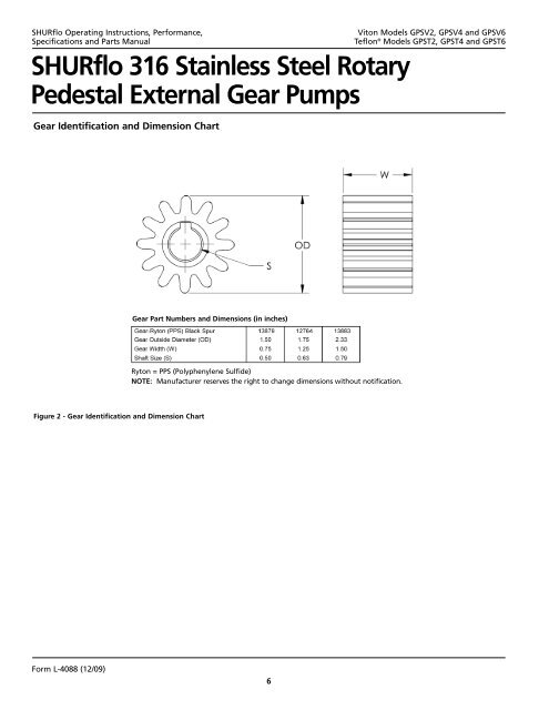
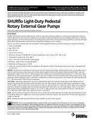
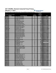
<strong>SHURflo</strong> Operating Instructions, Performance,Specifications and Parts Manual<strong>SHURflo</strong> 316 Stainless Steel RotaryPedestal External Gear PumpsGear Identification and Dimension ChartViton Models GPSV2, GPSV4 and GPSV6Teflon ® Models GPST2, GPST4 and GPST6Gear Part Numbers and Dimensions (in inches)Ryton = PPS (Polyphenylene Sulfide)NOTE: Manufacturer reserves the right to change dimensions without notification.Figure 2 - Gear Identification and Dimension ChartForm L-<strong>4088</strong> (12/09)6
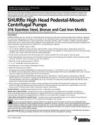
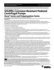
<strong>SHURflo</strong> Operating Instructions, Performance,Specifications and Parts ManualViton Models GPSV2, GPSV4 and GPSV6Teflon ® Models GPST2, GPST4 and GPST6Check motor.It may be equippedwith an automatic resetting thermalprotector and may restart unexpectedly(see specifications chart). Protector trippingis an indication of motor overloading as aresult of operating the pump at too high apressure (over 125 PSI), too high of viscosity,too high of specific gravity, excessively highor low voltage, inadequate wiring, incorrectmotor connections, too small a motor(sized incorrectly, not enough HP), or adefective motor or pump.Do not handle pump with wet handsor when standing in water. Failure tofollow the General Safety Informationand all warnings could result in fatalelectrical shock!InstallationIMPORTANT: In any installations whereproperty damage and/or personalinjury can occur when the pump isnot operating due to power outages,discharge line freezing, or any otherreason, a back-up system(s) and/orwarning system(s) should be used.In order to safely use this product,familiarize yourself with this pump andalso with the liquid (chemical, etc.) thatis going to be pumped through the unit.This pump is not suitable for manyliquids.1. Locate the pump as close to theliquid source as possible, makingthe suction line as short and directas possible.PIPINGSUCTION2. Avoid excessive lengths or number offittings and bends in the suction line.3. Attach suction line to suction inlet(See Figure 1 for proper rotation).4. It is recommended that same sizepipe as pump ports be used or, incases requiring lengthy piping, thenext larger size pipe be used.5. If suction lift is greater than what isindicated in the performance chart,attach a foot valve below liquidlevel at end of suction line toensure positive priming. Also note:If fluid specific gravity is greaterthan 1.4 or viscosity greaterthan 500 SSU, a foot valve is alsorecommended.NOTE: If a foot valve (or check valve) isnot used in the suction line, it may benecessary to refill the pump every timethe unit is stopped and you wish to restartthe pump. This depends on the length oftime between starts and whether or notthe gears are wet enough to close cavitiesto affect a prime.6. If solid contaminates are suspectedin a liquid, place a filter in thesuction line.7. Be certain all suction piping connectionsare airtight.NOTE: Assure airtight pipe connectionswith the use of a pipe joint sealant.DISCHARGE8. Attach discharge piping to thedischarge outlet.Support pump andpiping during assemblyand after installation. Failure to do so maycause piping to break, pump to fail, motorbearing failures, etc., all of whichcan result in property damage and/orpersonal injury.NOTE: Should the pump need to beself-draining, the pump head should bemounted in the vertical position withthe suction port facing down. Whenpumping high viscosity fluids, the verticalposition can be used with the suctionport facing up and the pumpmounted under the source. Increasingthe suction pipe size andeliminating bends and elbows alsoassists in pumping high viscosity fluids.Max. viscosity is 500 SSU at 1725 RPM.9. If a shut-off valve or handgun isrequired in discharge line, providea pressure relief valve for pumpprotection.Shutting offdischarge withoutproviding pressure relief can cause extremeoverpressure which can result in pumpand/or motor failure. Do not exceed 125 PSIpump or system pressure.10. Operation under shut-off dischargeconditions will overheat anddamage pump.NOTE: Globe valve or other restrictivevalves should not be used as shut-offmechanism as they are restrictive innature and will seriously affect pumpperformance.11. After all piping and controls (notsupplied with unit) have beeninstalled, unit is ready for operation.OperationDo not run pumpdry, as permanentdamage to the pump gears, seal, andbearings will result. Suction pressure shouldnever be greater than thedischarge pressure.1. All pumps must be primed beforestart-up and the seal chamber needsto be filled (See Figure 3). Neveroperate a pump unless it is securedto a solid foundation and all safetyshields are installed.Remove plug and fill seal chamberwith fluid and reinstall plugFigure 3 - Prime PlugUpon start-up, maintain a minimumof 15 PSI (1 BAR) operating pressureon the pump. This will allow anyremaining air to be driven from theForm L-<strong>4088</strong> (12/09)7