PS2 Controller Starter Kit SKPS User's Manual - Cytron Technologies
PS2 Controller Starter Kit SKPS User's Manual - Cytron Technologies
PS2 Controller Starter Kit SKPS User's Manual - Cytron Technologies

You also want an ePaper? Increase the reach of your titles
YUMPU automatically turns print PDFs into web optimized ePapers that Google loves.
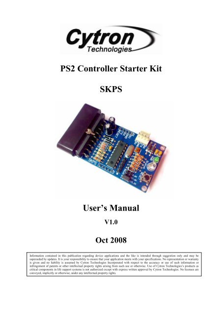
<strong>PS2</strong> <strong>Controller</strong> <strong>Starter</strong> <strong>Kit</strong><strong>SKPS</strong>User’s <strong>Manual</strong>V1.0Oct 2008Information contained in this publication regarding device applications and the like is intended through suggestion only and may besuperseded by updates. It is your responsibility to ensure that your application meets with your specifications. No representation or warrantyis given and no liability is assumed by <strong>Cytron</strong> <strong>Technologies</strong> Incorporated with respect to the accuracy or use of such information orinfringement of patents or other intellectual property rights arising from such use or otherwise. Use of <strong>Cytron</strong> <strong>Technologies</strong>’s products ascritical components in life support systems is not authorized except with express written approval by <strong>Cytron</strong> <strong>Technologies</strong>. No licenses areconveyed, implicitly or otherwise, under any intellectual property rights.
ROBOT . HEAD to TOEProduct User’s <strong>Manual</strong> – <strong>SKPS</strong>Index1. Introduction 12. System Overview 23. Packing List 34. Board Layout 45. Product Specification and Limitations 56. Hardware Interface 66.1 Microcontroller 66.2 Computer 86.3 <strong>PS2</strong> <strong>Controller</strong> 147. Protocol 197.1 Non-ASCII Mode (Microcontroller) 197.1.1 Button and <strong>PS2</strong> <strong>Controller</strong> Status 197.1.2 On Board Vibrator Motor Control 207.2 ASCII Mode (Computer) 217.2.1 Button and <strong>PS2</strong> <strong>Controller</strong> Status 217.2.2 Read Key Functions 227.2.3 On Board Vibrator Motor Control 238. Getting Started 249. Warranty 27Created by <strong>Cytron</strong> <strong>Technologies</strong> Sdn. Bhd. – All Rights Reserved
ROBOT . HEAD to TOEProduct User’s <strong>Manual</strong> – SK<strong>PS2</strong>. SYSTEM OVERVIEWSony <strong>PS2</strong><strong>Controller</strong>Created by <strong>Cytron</strong> <strong>Technologies</strong> Sdn. Bhd. – All Rights Reserved 2
ROBOT . HEAD to TOEProduct User’s <strong>Manual</strong> – <strong>SKPS</strong>3. PACKING LISTPlease check the parts and components according to the packing list. If there are any partsmissing, please contact us at sales@cytron.com.my immediately.1. 1 x <strong>SKPS</strong> board.2. 1 x mini jumper of <strong>SKPS</strong> board.3. 4 x 2510 iron pin.4. 1 x 2510 4 ways female connector.Note: <strong>SKPS</strong> does not come with <strong>PS2</strong> controller, please purchase separately from <strong>Cytron</strong><strong>Technologies</strong> website. It is advised to use <strong>PS2</strong> controller from <strong>Cytron</strong> <strong>Technologies</strong>because all <strong>PS2</strong> controller provided is tested before it is being shipped to costumer.Created by <strong>Cytron</strong> <strong>Technologies</strong> Sdn. Bhd. – All Rights Reserved 3
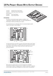
4. BOARD LAYOUTBROBOT . HEAD to TOEProduct User’s <strong>Manual</strong> – <strong>SKPS</strong>CADEFGLabelABCDEFGFunction<strong>PS2</strong> connector socket, please connect the <strong>PS2</strong> controller here5 ways header pin for external power and UART interface tomicrocontroller.4 ways 2510 header pin for external power and interface to PC ormicrocontroller also (depends to user).On board power indicator LED (Green)On board indicator LED (Blue) indicators for check connectionwith controller status.On board reset button for <strong>SKPS</strong>.Baud rate selector.A – Connector for <strong>PS2</strong> controllerB – 5 ways header pin for external power supply and UART interface.C – Alternative 4 ways 2510 header pin for external power supply and UART.D – On board power indicator LED. It should be ON if <strong>SKPS</strong> is powered by stable 5V.E – On board indicator LED, it indicators the connection status between <strong>SKPS</strong> and <strong>PS2</strong>controller.No controller connected: Blink<strong>Controller</strong> connected: On with 50% brightness<strong>Controller</strong> connected (button pressed): On with 100% brightnessF – Reset button for <strong>SKPS</strong> board.G – Baud rate selector. User may either choose 9600, 57600 or 115200 baud rate. Place thejumper to select the baud rate.Created by <strong>Cytron</strong> <strong>Technologies</strong> Sdn. Bhd. – All Rights Reserved 4
ROBOT . HEAD to TOEProduct User’s <strong>Manual</strong> – <strong>SKPS</strong>5. PRODUCT SPECIFICATION AND LIMITATIONS<strong>SKPS</strong> is designed to offer a compact and reliable <strong>PS2</strong> <strong>Controller</strong> Converter for user. Thespecifications are as listed below:Label Definition Function5VPower Input for<strong>SKPS</strong>External power source for <strong>SKPS</strong>, the typical voltage is5V. Please ensure this 5V source is a stable supply.Please do not use normal AC-DC adaptor to power it. It isrecommended to use linear regulator (7805) to provide5V supply.GND Ground or negative Ground of power and signal.RXTX<strong>SKPS</strong> UARTReceive signal<strong>SKPS</strong> UARTTransmit signalThis is <strong>SKPS</strong>’s receiver pin, it should be interfaced to 5Vlogic UART, no divider is necessary. This is an input pinto <strong>SKPS</strong>. It should be connected to microcontroller’stransmitter pin.This is <strong>SKPS</strong>’s transmitter pin; it should be interfaced to5V logic UART. This is an output pin from <strong>SKPS</strong>. Itshould be connected to microcontroller’s receiver pin.RESET <strong>SKPS</strong> Reset pinReset pin of <strong>SKPS</strong>. It should be connected to a pushbutton to Gnd, or NPN transistor.Absolute Maximum RatingSymbol Parameter Min Max Unit5V Power source for <strong>SKPS</strong> 4.5 5.5 VGND Operating voltage ground 0 0 VRX Receiver pin of <strong>SKPS</strong> 0 5.5 VTX Transmitter pin of <strong>SKPS</strong> 0 5.5 VRESET Reset pin of <strong>SKPS</strong> 0 5.5 VNOTE: <strong>SKPS</strong> can only be powered by either by PC through 4 way 2510 connector orexternal power (5V). The 5V must be a stable supply. Any ripple higher that 5.5V willspoil the controller on <strong>SKPS</strong> and it is not replaceable.Created by <strong>Cytron</strong> <strong>Technologies</strong> Sdn. Bhd. – All Rights Reserved 5
ROBOT . HEAD to TOEProduct User’s <strong>Manual</strong> – <strong>SKPS</strong>6. HARDWARE INTERFACEGenerally, there are 2 methods of using <strong>SKPS</strong>. It has been designed for interface toembedded system with 5V TTL (microcontroller) or connection to computer (normally forfunctionality test).6.1 MicrocontrollerOne of user’s main concerns when using <strong>SKPS</strong> is the interface with microcontroller.a. To begin, user may connect 5V and Gnd of <strong>SKPS</strong> to microcontroller board. Headersocket can be used to connect <strong>SKPS</strong> to microcontroller board.b. Once the 5V is supply to <strong>SKPS</strong>, the small green LED should light ON and Status LEDwill blink. After <strong>PS2</strong> is connected, it will stop blink and ON with half brightness.c. As 2 nd step, user might need to connect the RX and TX pin to microcontroller. Of course,these two pins should be cross connected to microcontroller. In other words, RX shouldbe connected to microcontroller’s Transmitter pin (TxD), while TX should be connectedto microcontroller’s Receiver pin (RxD). No extra component is necessary between theseconnections. For details connection, please refer to sample schematic.d. If configuration of UART is completed, <strong>SKPS</strong> is ready for embedded development.Sending and receiving data require software or firmware development on particularmicrocontroller.e. Finally, the RESET pin of <strong>SKPS</strong>. This is an optional pin for user as there is already areset button on <strong>SKPS</strong>. However, if user would like the microcontroller to reset <strong>SKPS</strong>during run time, a transistor is required for interface between microcontroller and <strong>SKPS</strong>.Please refer to following schematic for example of microcontroller interfacing with<strong>SKPS</strong>.Created by <strong>Cytron</strong> <strong>Technologies</strong> Sdn. Bhd. – All Rights Reserved 6
ROBOT . HEAD to TOEProduct User’s <strong>Manual</strong> – <strong>SKPS</strong>f. Any microcontroller with UART peripheral can be used to interface with <strong>SKPS</strong>.Example of connection to PIC16F877A microcontrollerCreated by <strong>Cytron</strong> <strong>Technologies</strong> Sdn. Bhd. – All Rights Reserved 7
ROBOT . HEAD to TOEProduct User’s <strong>Manual</strong> – <strong>SKPS</strong>6.2 Computer<strong>SKPS</strong> can be connected to PC for functionality test. Another main concern duringdevelopment using <strong>SKPS</strong> is to check the functionality. Normally, user will need to developRS232 level shifter for communication to serial port. This generates extra work just to checkthe functionality of <strong>SKPS</strong>. Furthermore, laptop and computer nowadays have phase-out theserial port, USB have replaced it. With these reasons, an USB to UART converter have beendeveloped. Now, no extra work is required to check the functionally of on board <strong>SKPS</strong>.Simply plug <strong>SKPS</strong> to UC00A and USB port of computer (PC or Laptop), install driver (1 sttime) and there is an extra virtual COM port ready for <strong>SKPS</strong>. Checking functionality issimple as 1, 2, 3.a. Simply connect UC00A to <strong>SKPS</strong>, another end (A type) of UC00A to PC as shown infollowing figure. User might need to connect the RX and TX pin toUC00A. Of course,these two pins should be cross connected to UC00A. In other words, RX should beconnected to UC00A’s Transmitter pin (Tx), while TX should be connected to UC00A’sReceiver pin (Rx). No extra component is necessary between these connections.Wires in pin 1 and 2 are crossed for the second connector.b. Please refer to document named “USB Driver Installation Guide” for driver installation.Created by <strong>Cytron</strong> <strong>Technologies</strong> Sdn. Bhd. – All Rights Reserved 8
ROBOT . HEAD to TOEProduct User’s <strong>Manual</strong> – <strong>SKPS</strong>c. After plug in the <strong>SKPS</strong> to computer and installation of driver, user is ready to test thefunctionality of <strong>SKPS</strong>. Open the HyperTerminal. Enter a name and choose an icon forconnection as picture below then click OK.d. Connect using USB Serial Port. If you are not sure which COM is it, please follow step(e) to (g).Created by <strong>Cytron</strong> <strong>Technologies</strong> Sdn. Bhd. – All Rights Reserved 9
e. Go to Start, right click on My Computer and choose Properties.ROBOT . HEAD to TOEProduct User’s <strong>Manual</strong> – <strong>SKPS</strong>Created by <strong>Cytron</strong> <strong>Technologies</strong> Sdn. Bhd. – All Rights Reserved 10
ROBOT . HEAD to TOEProduct User’s <strong>Manual</strong> – <strong>SKPS</strong>f. At System Properties Table, choose Hardware and click on Device Manager. DeviceManager Table will show out.g. At Device Manager Table, choose Ports (COM & LPT) and you can check your USBSerial Port COM. The Serial Port COM is “COM20” in this case.Created by <strong>Cytron</strong> <strong>Technologies</strong> Sdn. Bhd. – All Rights Reserved 11
ROBOT . HEAD to TOEProduct User’s <strong>Manual</strong> – <strong>SKPS</strong>h. Set the Port Setting as picture below. Bits per second must be same with <strong>SKPS</strong> Baud Rateand Flow control must be set to none. After finish setting, click Apply and then click OK.i. Go to File and select Properties. ‘skps’ Properties table will show. Choose Setting tab andclick ASCII Setup tab. Click on Echo typed characters locally and then click OK.Created by <strong>Cytron</strong> <strong>Technologies</strong> Sdn. Bhd. – All Rights Reserved 12
ROBOT . HEAD to TOEProduct User’s <strong>Manual</strong> – <strong>SKPS</strong>j. After all settings are complete, user may now check the functionality of <strong>SKPS</strong>. Pleaserefer ASCII Mode (PC) protocol in Section 6.2. Type “ae” to enable the return of any keypressed or changes of joystick automatically. Type “ad” to disable this feature.k. Make sure data is sent in correct protocol by <strong>SKPS</strong> when button or joystick is beingmanipulated (press or push). If the data can be obtained, the <strong>SKPS</strong> is working.Created by <strong>Cytron</strong> <strong>Technologies</strong> Sdn. Bhd. – All Rights Reserved 13
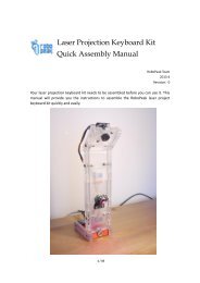
ROBOT . HEAD to TOEProduct User’s <strong>Manual</strong> – <strong>SKPS</strong>6.3 <strong>PS2</strong> <strong>Controller</strong>User may choose either wired or wireless <strong>PS2</strong> <strong>Controller</strong> to be connected to <strong>SKPS</strong>. Figurebelow shows the method to connect <strong>PS2</strong> controller to <strong>SKPS</strong> board. There are many types ofPS controller in the market and the sensitivity for each type also different. User is advised touse original <strong>PS2</strong> controller. <strong>Cytron</strong> <strong>Technologies</strong> does not guarantee compatibility for all <strong>PS2</strong>controllers.(a) Wireless Connection(b) Wired ConnectionCreated by <strong>Cytron</strong> <strong>Technologies</strong> Sdn. Bhd. – All Rights Reserved 14
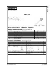
ROBOT . HEAD to TOEProduct User’s <strong>Manual</strong> – <strong>SKPS</strong>Figure below shows an example of <strong>PS2</strong> controller which can be used for <strong>SKPS</strong>. There are 16buttons that can be used as input button in <strong>PS2</strong> controller.L1, L2R1, R2TriangleUpLeftRightSelectStartSquareCircleDownCrossLeftJoystickRightJoystickAnalog value of Left Joystick and Right Joystick can be read from <strong>SKPS</strong>. There are 2 axesthat can be read which are Type 1 and Type 2. It will be mentioned briefly after this. User canuse either Type 1 or Type 2.Note: <strong>SKPS</strong> does not come with <strong>PS2</strong> controller, please purchase separately from <strong>Cytron</strong><strong>Technologies</strong> website. It is advised to use <strong>PS2</strong> controller from <strong>Cytron</strong> <strong>Technologies</strong>because all <strong>PS2</strong> controller provided is tested before it is being shipped to costumer.Created by <strong>Cytron</strong> <strong>Technologies</strong> Sdn. Bhd. – All Rights Reserved 15
ROBOT . HEAD to TOEProduct User’s <strong>Manual</strong> – <strong>SKPS</strong>For Type 1, there are 2 variables for each joystick which is axis X and axis Y. For exampleuser can move the joystick up, down for Y axis and left, right for X axis. For Y axis, whenusers move the joystick up, the value will change from 128 to 0; when user move the joystickdown, the value will change from 128 to 255. For X axis, when users move the joystick right,the value will change form 128 to 255; when user move the joystick left, the value willchange from 128 to 0. This axis is same for left joystick and right joystick on <strong>PS2</strong> controller.joy_lyjoy_ryjoy_lxjoy_rx(a) Type 1Let’s take an example on left joystick. Referring to the figure below, the left joystick ismoved a bit to the left and a bit to the up direction. So, the value of joy_lx and joy_ly willchanged, as in the figure joy_lx=70 and joy_ly=92.Created by <strong>Cytron</strong> <strong>Technologies</strong> Sdn. Bhd. – All Rights Reserved 16
ROBOT . HEAD to TOEProduct User’s <strong>Manual</strong> – <strong>SKPS</strong>For type 2, they are 4 variables for each joystick. The 4 variables are up, down, left and right.When users move the joystick up, down, left or right the value is at range 0-100. This axis issame for left joystick and right joystick on PS controller.(b) Type 2For example, when left joystick is being move 10% to left and 50% to down position, thevalue of joy_ll and joy_ld will change, as in figure below, joy_ll=10 and joy_ld=50. Howeverthe value of joy_lu=0 and joy_lr=0.Created by <strong>Cytron</strong> <strong>Technologies</strong> Sdn. Bhd. – All Rights Reserved 17
ROBOT . HEAD to TOEProduct User’s <strong>Manual</strong> – <strong>SKPS</strong>Please take note that the joy_lx, joy_ly, joy_rx and joy_ry is for type 1 axis; joy_lu, joy_ld,joy_ll, joy_lr, joy_ru, joy_rd, joy_rl and joy_rr is for type 2 axis. This variable is being nameaccording to a standard format.Created by <strong>Cytron</strong> <strong>Technologies</strong> Sdn. Bhd. – All Rights Reserved 18
ROBOT . HEAD to TOEProduct User’s <strong>Manual</strong> – <strong>SKPS</strong>7. PROTOCOL7.1 Non-ASCII Mode (Microcontroller)7.1.1 Button and <strong>PS2</strong> <strong>Controller</strong> StatusSend (decimal) Button of <strong>Controller</strong> Description0 select button1 left joystick center button2right joystick centerbutton3 start button <strong>SKPS</strong> will return the status of4 up buttoncorresponding button when the particulardecimal value is received5 right button 0 if the button is pressed6 down button 1 if button is not pressed7 left button8 L2 button9 R2 button10 L1 button11 R1 button12 triangle button13 circle button14 cross button15 square button16 left joystick x-axis17 left joystick y-axis18 right joystick x-axis19 right joystick y-axis20 left joystick up value21 left joystick down value22 left joystick left value23 left joystick right value24 right joystick up value25 right joystick down value26 right joystick left value27 right joystick right value28Example:If microcontroller sent 10 (decimal), <strong>SKPS</strong>will check L1 button status on <strong>PS2</strong><strong>Controller</strong>. <strong>SKPS</strong> will return0 if L1 button is pressed or1 if L1 is not pressed.<strong>SKPS</strong> will return the particular value ofcorresponding joystick in the selected axisExample :If microcontroller sent 20 (decimal), <strong>SKPS</strong>will read and return the value of leftjoystick up.<strong>SKPS</strong> will read controller status1 is return if controller is detectedCreated by <strong>Cytron</strong> <strong>Technologies</strong> Sdn. Bhd. – All Rights Reserved 19
ROBOT . HEAD to TOEProduct User’s <strong>Manual</strong> – <strong>SKPS</strong>7.1.2 On board Vibrator Motor Controlsend 1stbyte(decimal)send 2ndbyte(decimal)29 motor1 value<strong>Controller</strong>small vibrator placed on rightside30 motor2 value big vibrator placed on left sideDescriptionmotor1 = 1 or 0 (on or off)motor2 = 0 -> 255(adjustable vibration)(a) Example Communication of Circle Button Operation(b) Example Communication of Left Joystick Right Value OperationCreated by <strong>Cytron</strong> <strong>Technologies</strong> Sdn. Bhd. – All Rights Reserved 20
ROBOT . HEAD to TOEProduct User’s <strong>Manual</strong> – <strong>SKPS</strong>7.2 ASCII Mode (PC)7.2.1 Button and <strong>PS2</strong> <strong>Controller</strong> StatusSend 2byteupdwlfrgtrcrsqcistsejljrl1l2r1r2lxlyrxryluldlllrrurdrlrrcsunknownButton of <strong>Controller</strong>up buttondown buttonleft buttonright buttontriangle buttoncircle buttoncross buttonsquare buttonstart buttonselect buttonleft joystick center buttonright joystick center buttonL1 buttonL2 buttonR1 buttonR2 buttonleft joystick x-axisleft joystick y-axisright joystick x-axisright joystick y-axisleft joystick up valueleft joystick down valueleft joystick left valueleft joystick right valueright joystick up valueright joystick down valueright joystick left valueright joystick right valueDescription<strong>SKPS</strong> will return the status of correspondingbutton when the particular ASCII value isreceived‘0’ if the button is pressed‘1’ if button is not pressedExample:If microcontroller sent ‘r2’ (ASCII), <strong>SKPS</strong> willcheck R2 button status on <strong>PS2</strong> <strong>Controller</strong>. <strong>SKPS</strong>will return‘0’ if R2 button is pressed or‘1’ if R2 is not pressed.[“Enter” after every result]<strong>SKPS</strong> will return the particular value ofcorresponding joystick in the selected axis(3 byte, in ASCII).Example: ‘235’or ‘029’.[“Enter” after every result]<strong>SKPS</strong> will return the particular value ofcorresponding joystick in the selected axis(3 byte, in ASCII).Example: ‘039’or ‘027’.[“Enter” after every result]<strong>SKPS</strong> will read controller status‘1’ is return if controller is detected<strong>SKPS</strong> will return ‘x’ if unknown data is sent.Created by <strong>Cytron</strong> <strong>Technologies</strong> Sdn. Bhd. – All Rights Reserved 21
ROBOT . HEAD to TOEProduct User’s <strong>Manual</strong> – <strong>SKPS</strong>7.2.2 Read Key FunctionsSend 2byterkaeadReceived <strong>Controller</strong> Descriptionall key statusauto readenableauto readdisableany pressbutton/joystick valueany pressbutton/joystick valueany pressbutton/joystick value<strong>SKPS</strong> will return pressed key andchanged joystick value once.[“Enter” after result]<strong>SKPS</strong> will enable return pressedkey and changed joystickautomatically.[“Enter” after result]<strong>SKPS</strong> will disable return pressedkey and changed joystickautomatically.[“Enter” after result]Example communication of Auto Read Enable OperationCreated by <strong>Cytron</strong> <strong>Technologies</strong> Sdn. Bhd. – All Rights Reserved 22
ROBOT . HEAD to TOEProduct User’s <strong>Manual</strong> – <strong>SKPS</strong>7.2.3 On board Vibrator Motor ControlSend 2bytemeReceivedmotor enableDescription<strong>SKPS</strong> will enable vibrator motor (both motor1 andmotor2)md motor disable <strong>SKPS</strong> will disable vibrator motorExample Communication of Motor Enable Operation.Created by <strong>Cytron</strong> <strong>Technologies</strong> Sdn. Bhd. – All Rights Reserved 23
ROBOT . HEAD to TOEProduct User’s <strong>Manual</strong> – <strong>SKPS</strong>8. GETTING STARTEDFor this section, <strong>SKPS</strong> will be interfaced with PR23. Please refer PR23, DIY project from<strong>Cytron</strong> website for details example of interfacing to <strong>SKPS</strong>. PR23 shows the method of usingSKXBee, since <strong>SKPS</strong> UART pin is designed to be compatible to SKXBee, user may replaceSKXBee with <strong>SKPS</strong> on PR23. Please refer to http://www.cytron.com.my/PR23.asp for thedetails of PR23. For method of writing most simple program to use with <strong>SKPS</strong>, please refersteps below and for sample full version source code, user may get it from <strong>Cytron</strong> Website(same page as <strong>SKPS</strong>).a. Set the configuration for UART. Make sure the baud rate is correct.b. Definition of every button and joystick. For following example, “p_” is added in front of<strong>PS2</strong> controller label for easy understandable and avoid crash with other variable orinstructions.Created by <strong>Cytron</strong> <strong>Technologies</strong> Sdn. Bhd. – All Rights Reserved 24
ROBOT . HEAD to TOEProduct User’s <strong>Manual</strong> – <strong>SKPS</strong>c. Function to read <strong>SKPS</strong> and control the joystick. Below are examples of UART functionand <strong>SKPS</strong> function. Comments explain each command. UART function controls processof sending and receiving data via UART while <strong>SKPS</strong> function is to read information on<strong>PS2</strong> controller including function to read button and joystick and control the vibratormotor.d. Below are sample on how to use those function that mentioned above. For first command,when L1 is pressed, buzzer will beep. Second command is to test if there is any obstaclein front. For PR23 we use ultrasonic sensors to detect the obstacles. If obstacle isdetected, motor in <strong>PS2</strong> controller will vibrate.NOTE: User may download this sample source code from product page of <strong>SKPS</strong>.Created by <strong>Cytron</strong> <strong>Technologies</strong> Sdn. Bhd. – All Rights Reserved 25
ROBOT . HEAD to TOEProduct User’s <strong>Manual</strong> – <strong>SKPS</strong>e. After finish writing the program, user may compile it and load the source code. Pleaserefer to PR23 on the method to download the code.f. Upon loading the program, PR23 is now ready to operate with <strong>SKPS</strong>. User may test itusing <strong>PS2</strong> controller, try each button and function. Have fun!Created by <strong>Cytron</strong> <strong>Technologies</strong> Sdn. Bhd. – All Rights Reserved 26
ROBOT . HEAD to TOEProduct User’s <strong>Manual</strong> – <strong>SKPS</strong>9. WARRANTY‣ Product warranty is valid for 6 months.‣ Warranty only applies to manufacturing defect.‣ Damage caused by mis-use is not covered under warranty.‣ Warranty does not cover freight cost for both ways.Prepared by<strong>Cytron</strong> <strong>Technologies</strong> Sdn. Bhd.19, Jalan Kebudayaan 1A,Taman Universiti,81300 Skudai,Johor, Malaysia.Tel: +607-521 3178Fax: +607-521 1861URL: www.cytron.com.myEmail: support@cytron.com.mysales@cytron.com.myCreated by <strong>Cytron</strong> <strong>Technologies</strong> Sdn. Bhd. – All Rights Reserved 27