
You also want an ePaper? Increase the reach of your titles
YUMPU automatically turns print PDFs into web optimized ePapers that Google loves.
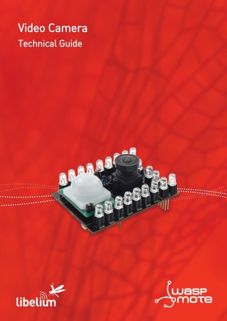
<strong>Video</strong> <strong>Camera</strong>Technical Guidewaspmote
IndexDocument version: v4.0 - 04/2013© <strong>Libelium</strong> Comunicaciones Distribuidas S.L.INDEX1. General.................................................................................................................................................. 41.1. General and safety information...............................................................................................................................................41.2. Conditions of use..........................................................................................................................................................................42. Hardware............................................................................................................................................... 52.1. Introduction....................................................................................................................................................................................52.2. General Description.....................................................................................................................................................................52.3. Specifications.................................................................................................................................................................................62.4. Electrical Characteristics.............................................................................................................................................................62.5. Assembling......................................................................................................................................................................................73. Sensors.................................................................................................................................................. 93.1. <strong>Camera</strong> Sensor...............................................................................................................................................................................93.1.1. Specifications..................................................................................................................................................................93.1.2. Measurement Process.................................................................................................................................................93.2. Luminosity sensor.........................................................................................................................................................................93.2.1. Specifications..................................................................................................................................................................93.2.2. Usage.................................................................................................................................................................................93.2.3. Measurement process.................................................................................................................................................93.2.4. Socket..............................................................................................................................................................................103.3. IR sensor........................................................................................................................................................................................103.3.1. Specifications................................................................................................................................................................103.3.2. Usage...............................................................................................................................................................................113.3.3. Measurement process...............................................................................................................................................113.3.4. Socket..............................................................................................................................................................................113.4. Presence sensor (PIR)................................................................................................................................................................113.4.1. Specifications................................................................................................................................................................113.4.2. Usage...............................................................................................................................................................................123.4.3. Measurement process...............................................................................................................................................123.4.4. Socket..............................................................................................................................................................................134. Night Vision......................................................................................................................................... 144.1. IR lighting......................................................................................................................................................................................154.1.1. Description...................................................................................................................................................................154.1.2. Specifications................................................................................................................................................................154.2. IR cut filter.....................................................................................................................................................................................174.2.1. Description....................................................................................................................................................................174.2.2. Specifications................................................................................................................................................................17-2- v4.0
Index5. Board configuration and programming........................................................................................... 185.1. Focusing the lens with microSD card.................................................................................................................................185.2. Focusing the lens via videocall.............................................................................................................................................195.3. Focusing the lens with calibration program (only for Windows)..............................................................................205.4. Battery............................................................................................................................................................................................225.5. API....................................................................................................................................................................................................225.5.1. Starting the camera....................................................................................................................................................225.5.2. Stoping the camera....................................................................................................................................................225.5.3. Configurating the resolution..................................................................................................................................235.5.4. Configurating the brightness.................................................................................................................................235.5.5. Configurating the rotation.......................................................................................................................................245.5.6. Configurating the FPS...............................................................................................................................................245.5.7. Configurating the picture name............................................................................................................................255.5.8. Adding time stamp on pictures.............................................................................................................................255.5.9. Taking pictures.............................................................................................................................................................255.5.10. Recording videos......................................................................................................................................................265.5.11. Making videocalls.....................................................................................................................................................265.5.12. Setting the video quality ......................................................................................................................................275.5.13. Sending DMTF tones ..............................................................................................................................................275.5.14. Managing IR LEDs.....................................................................................................................................................285.5.15. Managing IR cut filter..............................................................................................................................................285.5.16. Managing interrupts................................................................................................................................................285.6. Example code..............................................................................................................................................................................296. Sending the photos and videos......................................................................................................... 326.1. Sending photos and videos by 3G/GPRS..........................................................................................................................346.2. Sending photos and videos by XBee (DigiMesh)...........................................................................................................356.3. Sending photos and videos by WiFi....................................................................................................................................366.4. Sending time...............................................................................................................................................................................366.5. API....................................................................................................................................................................................................376.5.1. Sending pictures or videos to Meshlium with XBee DigiMesh..................................................................376.5.2. Sending pictures or videos to a FTP server with WiFi....................................................................................376.5.3. Sending pictures or videos to a FTP server with 3G/GPRS Board..............................................................386.5.4. Sending a picture as attachment of an email with 3G/GPRS Board.........................................................397. Consumption...................................................................................................................................... 408. Maintenance....................................................................................................................................... 419. Disposal and recycling....................................................................................................................... 42-3- v4.0
General1. General1.1. General and safety information••In this section, the term “Waspmote” encompasses both the Waspmote device itself and its modules and sensor boards.••Read through the document “General Conditions of <strong>Libelium</strong> Sale and Use”.••Do not allow contact of metallic objects with the electronic part to avoid injuries and burns.••NEVER submerge the device in any liquid.••Keep the device in a dry place and away from any liquid which may spill.••Waspmote consists of highly sensitive electronics which is accessible to the exterior, handle with great care and avoidbangs or hard brushing against surfaces.••Check the product specifications section for the maximum allowed power voltage and amperage range and consequentlyalways use a current transformer and a battery which works within that range. <strong>Libelium</strong> is only responsible for the correctoperation of the device with the batteries, power supplies and chargers which it supplies.••Keep the device within the specified range of temperatures in the specifications section.••Do not connect or power the device with damaged cables or batteries.••Place the device in a place only accessible to maintenance personnel (a restricted area).••Keep children away from the device in all circumstances.••If there is an electrical failure, disconnect the main switch immediately and disconnect that battery or any other powersupply that is being used.••If using a car lighter as a power supply, be sure to respect the voltage and current data specified in the “Power Supplies”section.••If using a battery in combination or not with a solar panel as a power supply, be sure to use the voltage and current dataspecified in the “Power supplies” section.••If a software or hardware failure occurs, consult the <strong>Libelium</strong> Web Development section.••Check that the frequency and power of the communication radio modules together with the integrated antennas areallowed in the area where you want to use the device.••Waspmote is a device to be integrated in a casing so that it is protected from environmental conditions such as light, dust,humidity or sudden changes in temperature. The board supplied “as is” is not recommended for a final installation as theelectronic components are open to the air and may be damaged.1.2. Conditions of use••Read the “General and Safety Information” section carefully and keep the manual for future consultation.••Use Waspmote in accordance with the electrical specifications and the environment described in the “Electrical Data”section of this manual.••Waspmote and its components and modules are supplied as electronic boards to be integrated within a final product. Thisproduct must contain an enclosure to protect it from dust, humidity and other environmental interactions. In the event ofoutside use, this enclosure must be rated at least IP-65.••Do not place Waspmote in contact with metallic surfaces; they could cause short-circuits which will permanently damage it.Further information you may need can be found at: http://www.libelium.com/development/waspmoteThe “General Conditions of <strong>Libelium</strong> Sale and Use” document can be found at:http://www.libelium.com/development/waspmote/technical_service-4- v4.0
Hardware2. Hardware2.1. IntroductionThe new <strong>Video</strong> <strong>Camera</strong> Sensor board in conjunction with the 3G module for Waspmote allows to take photos (VGA - 640x480)and record videos (QVGA - 320x240) and send them to the Cloud by using high speed WCDMA and HSPA cellular networks in thesame way as Smartphones do. This makes possible sensor nodes send not only discrete sensor information such as temperatureor humidity (which can be encoded using just a single number) but also complex streams of information such as photos andvideos. This new feature allows developers the creation of new Smart Security applications.The 3G module offers speed rates of 7.2Mbps in download mode and 5.5Mbps when uploading to the Cloud photos and videostaken by the <strong>Video</strong> <strong>Camera</strong> Sensor board, which makes possible to create a distributed photo/video network where hundredsof small sensor nodes send at the same time the information captured.The new <strong>Video</strong> <strong>Camera</strong> Sensor board includes 22 high power infrared (IR) LED’s to implement the night vision mode - allowingWaspmote take pictures and record videos in total darkness- . This mode is activated automatically changing the IR filter underthe lens by using the luminosity information given by two sensors integrated on the board, a LDR sensor to capture the visiblelight (400-600nm) and an infrared sensor to measure the IR levels (600-1000nm).Each Waspmote sensor node may integrate at the same time a medium range radio such as 802.15.4/ZigBee/Bluetooth/WiFiand one long range 3G radio. This way we can minimize costs by using the mobile network just when really needed.The 3G module comes with an internal SD Card of 2GB (extended up to 32GB) which is used to store the photos and videostaken by the <strong>Video</strong> <strong>Camera</strong> Sensor Board without the need of being handled by the node MCU. This ensures we get real speedranges (7.2Mbps download and 5.5Mbps upload) as the communication is direct between the SD and the 3G module.The 3G module counts also with an internal GPS that enables the location of the device outdoors and indoors combiningstandard NMEA frames with mobile cell ID triangulation using both assisted-mobile (A-GPS) and mobile-based (S-GPS) modes.By using the information given by the GPS we can add meta information to the multimedia files setting the geolocation ofwhere the pictures and videos are taken.2.2. General DescriptionThe <strong>Video</strong> <strong>Camera</strong> Sensor Board allows to Waspmote to take pictures and record video along with the Waspmote 3G/GPRSboard. The board includes 22 IR LEDs, divided in two blocks controlled each one by transistors, to give extra illumination andrecord with few light or in the night. To eliminate the IR distortion when the board is used with natural light, the board has afilter exchanger with a IR light filter.The board has two sockets for a LDR and a IR photodiode. With the information of these sensors the users can select the properfilter and, if is necessary, to use the IR LEDs.The <strong>Video</strong> <strong>Camera</strong> Sensor Board also includes a presence sensor (PIR), to generate an interruption on Waspmote and take apicture or record a video when a person passes by, this feature is specially designed for security and surveillance applications.-5- v4.0
Hardware2.3. SpecificationsWeight (with sensors): 43grDimensions: 73 x 53 x 1.3 mmTemperature Range: [-25ºC, 70ºC]Figure 1: <strong>Video</strong> <strong>Camera</strong> Sensor Board2.4. Electrical CharacteristicsIR LED power voltages:3,6V – 4,2V (from battery)IR cut filter exchanger power voltages:3,6V - 4,2V (from battery)Image Sensor Analog Voltage: 3,3VImage Sensor Digital I/O Voltage:2,8V (from Waspmote 3G/GPRS board)LDR and IR photodiode Sensor Voltage: 3,3VPIR Sensor Voltage: 3,3VMaximum admitted current (continuous) for sensors: 200mAIR LED maximum current (continuous) for block 1: 1AIR LED maximum current (continuous) for block 2: 1A-6- v4.0
Hardware2.5. AssemblingThe board needs to be assembled along with the 3G/GPRS board as the photos and video are handled and stored by it. Oncethey are stored in the internal SD of the 3G module, they can be sent using the 3G radio or passed to the Waspmote MCUand then sent by other radios such as the WiFi or the XBee 802.15.4 / ZigBee / DigiMesh. Read more about this in the section“Sending photos and videos”.Follow the next steps to assemble correctly the boards:••Connect the battery to Waspmote.••Insert the microSD card and the SIM card (if necessary).Figure 2: Inserts microSD card••Connect the FPC to the Waspmote <strong>Video</strong> <strong>Camera</strong> Sensor board. To do this, first pull carefully out the sides of the connector,inserts the FPC with metallic contacts facing up and, at the final step, push in the laterals of the connector to close it.1 2 3Figure 3: Connecting FPC bus to <strong>Video</strong> <strong>Camera</strong> Sensor Board-7- v4.0
Hardware••Follow the same steps to connect the FPC to the Waspmote 3G/GPRS board.••Connect the Waspmote 3G/GPRS board in the socket 1 on Waspmote.Figure 4: Mounting 3G/GPRS board in Waspmote••Insert the <strong>Video</strong> <strong>Camera</strong> Sensor board on Waspmote. Beware, the last two pins of the 2x12 connector (the nearest of thecorner) must be empty.Figure 5: Mounting <strong>Video</strong> <strong>Camera</strong> Sensor Board in Waspmote••Insert the PIR sensor, the luminosity sensor and the IR sensor. The IR sensor has polarity. Please, refer to chapter “IR sensor”for more information.Figure 6: Connecting sensors-8- v4.0
Sensors3. Sensors3.1. <strong>Camera</strong> Sensor3.1.1. SpecificationsWidth(min.): 24mmHeight: 24mmLength: 17mmMax resolution: 640x480 for pictures, 320x240 for videoImage Sensor Analog Voltage: 3,3VImage Sensor Digital I/O Voltage: 2,8V (from Waspmote 3G/GPRS board)Temperature range:operating: -30°C to 70°C junction temperaturestable image: 0°C to 50°C junction temperatureConsumption (active): 48 mAAngle of view: 70ºFigure 7: <strong>Camera</strong> sensor with IRcut filter and lens3.1.2. Measurement ProcessThe image sensor is fully managed by Waspmote 3G/GPRS board. Please, refer to API chapter for more information.3.2. Luminosity sensor3.2.1. SpecificationsResistance in darkness: 20MΩResistance in light (10lux): 5 ~ 20kΩSpectral range: 400 ~ 700nmOperating Temperature: -30ºC ~ +75ºCMinimum consumption: 0uA approximatelyFigure 8: Light sensor LDR3.2.2. UsageWith this sensor we can know the level of visible light and we can decide if switch on or switch off the blocks of IR LED.3.2.3. Measurement processThis is a resistive sensor whose conductivity varies depending on the intensity of light received on its photosensitive part. Themeasurement of the sensor is carried out through the analog-to-digital converter of the microcontroller, reading the resultingvoltage out of a voltage divider formed by the sensor itself and the load resistor of 10kΩ.The measurable spectral range (400nm – 700nm) coincides with the human visible spectrum so it can be used to detect light/darkness in the same way that a human eye would detect it.The sensor value can be read with the next function:{LDR_value = readAnalog(SENS_LDR);}-9- v4.0
Sensors3.2.4. SocketLuminosity sensorFigure 9: Socket for luminosity sensor3.3. IR sensor3.3.1. SpecificationsPeak sensitivity wavelength: 860nmCollector dark current (Ee=1mW/cm2): 100nAOperating Temperature: -25ºC ~ +85ºCFigure 10: IR sensorFigure 11: Photo Current vs. Irradiance taken from the Premier Farnell Group sensor data sheet-10- v4.0
Sensors3.3.2. UsageWith this sensor we can know the level of IR light and we can decide if enable the IR cut filter filtering the IR light or disable theIR cut filter allowing the pass to all light.3.3.3. Measurement processThis is a transistor in wich the current of this base varies depending on the intensity of the light received on its photoelectricpart. The current generated in base allow the conduction of current througth collector-emiter. The current produces a voltagein a resistance connected between the emmiter of the phototransistor and ground. The voltage of the resistance can be readthrough the analog-to-digital converter of the microcontroller.The sensor value can be read with the next function:{IR_value = readAnalog(SENS_IR);}3.3.4. SocketIR sensorPolarity sensitive. Flat side of thepackage (T-1 3mm) in this sideFigure 12: Socket for IR sensor3.4. Presence sensor (PIR)3.4.1. SpecificationsHeight: 25.4mmWidth: 24.3mmLength: 28.0mmConsumption: 100μARange of detection: 6 ~ 7mSpectral range: ~ 10μmFigure 13: PIR presence sensor-11- v4.0
Sensors3.4.2. UsageThis sensor allows to the <strong>Video</strong> <strong>Camera</strong> Sensor Board generate an interrupt in Waspmote when the presence sensor detects, forexample, a person or an animal.3.4.3. Measurement processThe PIR sensor (Passive Infra-Red) is a pyroelectric sensor mainly consisting of an infra-red receiver and a focusing lens that basesits operation on the monitoring of the variations in the levels of reception of detected infra-reds, reflecting this movement bysetting its output signal high.The 10μm spectrum corresponds to the radiation of heat from the majority of mammals as they emit temperatures around 36°C.The maximum detection direction goes perpendicular to the <strong>Video</strong> <strong>Camera</strong> Sensor Board.Figure 14: PIR maximun detection rangeFigure 15: Maximun range jumper configuration-12- v4.0
SensorsThe connection between Waspmote and the PIR sensor has been designed to generate an interruption. When the PIR detects achange of state, it changes his output from ‘0’ to ‘1’. This change generates an interruption in Waspmote by UART1. Before to usethe UART1, the monitorization pin (PIR_3G_PIN_MON) must be forced to ‘0’ to allow the connection with the Waspmote 3G/GPRS board. This can be done with the function disablePIRInterrupt(). Please, refer to API chapter for more information.3.4.4. SocketThe sensor must situated in the PIR socket (see figure below):Present sensorFigure 16: Socket for presence sensor-13- v4.0
Night Vision4.1. IR lighting4.1.1. DescriptionThe <strong>Video</strong> <strong>Camera</strong> Sensor Board have 22 IR LEDs divided in two blocks controlled each one by transistors, to give extra iluminationand record with few light or in the night. Block 1 can be controlled by pin DIGITAL6 (POWER_LED) and the block 2 by pinDIGITAL8 (POWER_LED2) or using the function powerIRLED(). Please, refer to API chapter for more information.Block 1Block 2Figure 24: IR LED blocksFigure 25: IR LEDs activated4.1.2. SpecificationsBlock 1Number of LEDs: 8Total current consumption: 200mA at 3,7V; 270mA at 4,2VCurrent for each LED: 50mA at 3,7V; 67,5mA at 4,2VBlock 2Number of LEDs: 14Total current consumption: 390mA at 3,7V;490mA at 4,2VCurrent for each LED: 48,75mA at 3,7V; 61,25mA at 4,2VLED descriptionModel: HIR7393CPeak wavelength: λp=850nmView Angle: 50º-15- v4.0
Night VisionFigure 26: Relative Intensity vs. Forward Current taken from the Everlight Electronics Co., Ltd.Figure 27: Relative Radiant Intensity vs. Angular Displacement taken from the Everlight Electronics Co., Ltd. data sheet-16- v4.0
5. Board configuration and programming5.1. Focusing the lens with microSD cardBoard configuration and programming1º Load the code “Focusing the lens with microSD” in Waspmote. The code is in the examples section.2º Open the serial monitor and wait for the picture3º Check the picture in the microSD card and if it is necessary, loosen the fixing screw of the lens and rotate the lens in little steps.Figure 30: Loosing the fixing screw4º Insert the microSD in Waspmote 3G/GPRS board and repeat the step 3 until focus the lens.5º Tighten the fixing screw of the lens and power off Waspmote.Figure 31: Tighten the fixing screw-18- v4.0
Board configuration and programming5.2. Focusing the lens via videocallA fast method to calibrate the lens is to make a videocall with Waspmote assembled and in the installation place.1º Open the code “Focusing the lens via videocall”, put your phone number in ‘phone_number’ variable and load the code inWaspmote. The code is in the 3G examples section of Waspmote IDE2º Wait the videocall in your phone.3º Loosen the fixing screw of the lens and rotate the lens until you can focus correctly.Figure 32: Loosing the fixing screw4º Tighten the fixing screw of the lens and hang the videocall in the phone.Figure 33: Tighten the fixing screw-19- v4.0
Board configuration and programming5.3. Focusing the lens with calibration program (only for Windows)1º Load the code “Focusing the lens with calibration program” in Waspmote from 3G examples of Waspmote IDE2º Connect the Waspmote 3G/GPRS board to your computer with the miniUSB connector. Then power on Waspmote.Figure 34: USB connector on Waspmote 3G/GPRS board3º Open the <strong>Camera</strong>Demo.exe and select SIM5218Figure 35: Select SIM5218 in <strong>Camera</strong>Demo program-20- v4.0
Board configuration and programming4º Loosen the fixing screw of the lens and rotate the lens until you can focus correctly.Figure 36: Loosing the fixing screw5º Tighten the fixing screw of the lens and press disconnect button in <strong>Camera</strong>Demo. Close <strong>Camera</strong>Demo and unplug the USBfrom Waspmote 3G/GPRS board.Figure 37: Tighten the fixing screwFigure 38: Disconnect the module and close <strong>Camera</strong>DemoNow, the <strong>Video</strong> <strong>Camera</strong> Sensor Board have the lens calibrated. You can load your code on Waspmote.-21- v4.0
Board configuration and programming5.5.3. Configurating the resolutionThe camera can be configurated with 6 differents resolutions. The next table shows the resolution, the number of horizontal andvertical pixels and the library parameter to use with the function.Resolution HxV(pixels) library parameterSTAMP 80x48 0QQVGA 160x120 1QCIF 176x144 2QVGA 320x240 3CIF 352x288 4VGA 640x480 5The highest resolution for pictures are VGA (5) and for videos are QVGA (3).Example of use:{// Sets QVGA resolution_3G.cameraResolution(3);}This function returns:••‘1’ on success••‘0’ if error••‘-2’ if camera not detected••‘-3’ if camera not started5.5.4. Configurating the brightnessThe camera have seven levels of brightness, from 0 to 6 (0 is the lowest, 6 is the highest).Example of use:{// Sets highest brightness_3G.cameraBrightness(6);}This function returns:••‘1’ on success••‘0’ if error••‘-2’ if camera not started••‘-3’ if camera is in invalid state-23- v4.0
Board configuration and programming5.5.7. Configurating the picture nameThe name of the pictures can be customized by the user. The name can have up to 20 characters. The name is only a part of thewhole name; the whole name is namexxxx.jpg where xxxx is an index of the picture after user defined name.Example of use:{// Sets the name of the pictures// The final name is → Test_name_xxxx.jpg_3G.pictureName(“Test_name_”);}This function returns:••‘1’ on success••‘0’ if error5.5.8. Adding time stamp on picturesThe function pictureTimeStamp() allows to add a time stamp with the date and time of the 3G module.Example of use:{// Adds time stamp_3G.pictureTimeStamp(1);// Don’t add time stamp_3G.pictureTimeStamp(0);}This function returns:••‘1’ on success••‘0’ if error5.5.9. Taking picturesThe function takePicture() takes a picture and stores it in the folder “Picture”. To select if store in the module memory orthe external microSD card use the function selectStorage().Example of use:{// Takes a picture:_3G.takePicture ();}This function returns:••‘1’ on success••‘0’ if error••‘-2’ if camera not started••‘-3’ if camera is in invalid state••‘-4’ if there isn’t memory enough-25- v4.0
Board configuration and programming5.5.10. Recording videosThere are 4 functions related with recording a video:••start<strong>Video</strong>(). Starts the recording of the video••pause<strong>Video</strong>(). Pauses the recording of the video••resume<strong>Video</strong>(). Resumes the recording of the video••stop<strong>Video</strong>(). Stops the recording of the videoExample of use:{}// Starts the recording:_3G.start<strong>Video</strong>();// Records 15 seconds and pauses:delay(15000);_3G.pause<strong>Video</strong>();// Waits 5 seconds and resumes the record:delay(5000);_3G.resume<strong>Video</strong>();// Records 15 seconds and stops:delay(15000);_3G.stop<strong>Video</strong>();The function start<strong>Video</strong>() returns:••‘1’ on success••‘0’ if error••‘-2’ if camera not started••‘-3’ if camera is in invalid state••‘-4’ if there isn’t memory enoughThe functions pause<strong>Video</strong>(), resume<strong>Video</strong>() and stop<strong>Video</strong>() return:••‘1’ on success••‘0’ if error••‘-2’ if camera not started••‘-3’ if camera is in invalid state5.5.11. Making videocallsIt makes a videocall to the given telephone number. To do this you can use the function make<strong>Video</strong>Call(phone_number,record). The input parameter ‘record’ allow to record the videocall. ‘0’ not record video, ‘1’ only record far-end video, ‘2’ onlyrecord near-end video and ‘3’ record both far-end and near-end, The video files have been saved in the folder <strong>Video</strong>Call/Example of use :{// Makes a videocall and record both far-end and near-end:_3G.make<strong>Video</strong>Call(“*********”, 3);}-26- v4.0
Board configuration and programmingThis function returns:••‘1’ if success••‘0’ if error••‘-1’ if error connecting to the other party,••‘-2’ if error with setup or the other party hangs the call••‘-3’ if error connecting the videocall••‘-4’ if error recording the call (videocall is active)To hang a videocall use the function hang<strong>Video</strong>Call().Example of use:{// Hangs the active videocall:_3G.hang<strong>Video</strong>Call();}This function returns:••‘1’ if success••‘0’ if error5.5.12. Setting the video qualityThe video quality can be selected with the function <strong>Video</strong>CallQuality(<strong>Video</strong>Quality). The parameter ‘<strong>Video</strong>Quality’can be between 5 for 5 for high quality image or 15 for high motion profile.Note: This function can be used only when videocall is in idle state, and the setting is available until power off.Example of use:{// Sets high quality image:_3G.<strong>Video</strong>CallQuality(5);}This function returns:••‘1’ if success••‘0’ if error5.5.13. Sending DMTF tonesDMTF tones can be sent during a videocall. Allowed tones are 0–9, * and #.Example of use:{// Sends an example string:_3G.<strong>Video</strong>CallDMTF(“0123456789*#);}This function returns:••‘1’ if success••‘0’ if error-27- v4.0
Board configuration and programming5.5.14. Managing IR LEDsThe IR LED blocks of the <strong>Video</strong> <strong>Camera</strong> Sensor Board can be managed with the function powerIRLED(IR_block). The inputparameter ‘IR_block’ selects the illumination level: ‘0’ powers off all LEDs, ‘1’ powers on block 1, ‘2’ powers on block 2 and ‘3’powers all LEDs.Example of use:{// Power on IR LED block 1_3G.powerIRLED(1);}This function returns nothing.5.5.15. Managing IR cut filterThe IR cut filter is managed with the function selectFilter(filter_state). The input parameter ‘filter_state’ selectsthe state of the filer: ‘0’ enables the IR cut filter and ‘1’ disables the filter.Example of use:{// Power on IR LED block 1_3G.powerIRLED(1);}This function returns nothing.5.5.16. Managing interruptsPresence sensor allows to generate interrupts in Waspmote. The function enablePIRInterrupt() sets the 3G/GPRS Boardin sleep mode, it activates the presence sensor and it waits until the sensor be ready.The function disablePIRInterrupt(PIR_state) must be used when an interrupt occurs. The parameter ‘PIR_state’selects if the presence sensor it’s power off (PIR_state is ‘0’) and still active (PIR_state is ‘1’). The function blocks presencesensor to generate interrupts and wake up the 3G/GPRS from sleep mode. When a new interrupt is required use the functionenableInterrupt().These functions return nothing.The example code showed below use the interrupts functions to take the picture.-28- v4.0
Board configuration and programming5.6. Example codeWe provide below with a code suitable for take a picture and send via FTP server. Take into account that to work with thisexample you need a FTP account./** This example shows how use the presence sensor interrupt taking a* picture and uploading it when the interrupt occurs. To use this example,* a <strong>Video</strong> <strong>Camera</strong> Sensor Board with presence sensor is required.** Copyright (C) 2013 <strong>Libelium</strong> Comunicaciones Distribuidas S.L.* http://www.libelium.com** This program is free software: you can redistribute it and/or modify* it under the terms of the GNU General Public License as published by* the Free Software Foundation, either version 3 of the License, or* (at your option) any later version.** This program is distributed in the hope that it will be useful,* but WITHOUT ANY WARRANTY; without even the implied warranty of* MERCHANTABILITY or FITNESS FOR A PARTICULAR PURPOSE. See the* GNU General Public License for more details.** You should have received a copy of the GNU General Public License* along with this program. If not, see .** Version: 1.0* Design: David Gascón* Implementation: Alejandro Gállego*/#include “Wasp3G.h”int count=0;int answer=0;char picture_name[30];void setup(){USB.ON();USB.println(F(“Starting”));// Activates the 3G module:while (_3G.ON() != 1){USB.println(F(“Waiting...”));}USB.println(F(“3G module ready...”));_3G.setTime();_3G.setMode(_3G_RF_OFF);USB.println(F(“RF circuits disabled”));// if there isn’t a name the 3G module use the date and time for the picture’s name_3G.pictureName(“”);// waits for SD and then selects as storageUSB.println(“Waiting for SD...”);while ((_3G.isSD() == 0));_3G.selectStorage(1);}intArray[PIR_3G_POS] = 0;-29- v4.0
Board configuration and programmingvoid loop(){USB.print(F(“Enabling PIR interrupt...”));_3G.enablePIRInterrupt();USB.println(F(“ready”));// waits the interruptdo{PWR.sleep(0);}while ( intFlag & PIR_3G_INT == 0);USB.println(F(“PIR interrupt detected”));// disables the interrupt and start communications with the 3G module_3G.disablePIRInterrupt(1);USB.println(F(“Changes power mode to full”));_3G.setMode(_3G_FULL);// starts the camera and configures itcount = 3;do{answer[0] = _3G.start<strong>Camera</strong>();// if the camera is started (before start<strong>Camera</strong> function), stops itif(answer[0]==-3){_3G.stop<strong>Camera</strong>();}count--;}while((answer[0] != 1) && (count > 0));if (answer == 1){// configures the camera_3G.cameraResolution(5);_3G.cameraBrightness(3);count = 3;do{// power on the LED light if its necesary_3G.autoLight();answer = _3G.takePicture();// power off the LEDs_3G.powerIRLED(0);count--;}while ((answer != 1) && (count > 0));// saves the name of the picturestrcpy(picture_name, _3G.buffer_3G);// stops the camera_3G.stop<strong>Camera</strong>();if (answer == 1){USB.println(F(“Picture captured!”));USB.print(F(“Connecting to the network...”));while (_3G.check() == 0);USB.println(F(“connected”));1, “I”);// configures 3G connection for FTPanswer = _3G.configureFTP(“server_name”, “server_port”, “user_name”, “password”,-30- v4.0
Board configuration and programmingif (answer == 1){USB.print(F(“Uploading the picture...”));USB.println(picture_name);// uploads file from SD card to the FTP server:answer = _3G.uploadFile(4, picture_name, 60);if (answer == 1){USB.println(F(“Upload done”));}else if(answer == -2){USB.print(F(“Upload failed. Error code: “));USB.println(answer, DEC);USB.print(F(“CME error code: “));USB.println(_3G.CME_CMS_code, DEC);}else{USB.print(F(“Upload failed. Error code: “));USB.println(answer, DEC);}}else{USB.print(F(“Configuration failed. Error code:”));USB.println(answer, DEC);}}else{USB.print(F(“Error taking the picture. Error code:”));USB.println(answer, DEC);}}else{USB.print(“Error starting the camera. Error code: “);USB.println(answer, DEC);}}_3G.setMode(_3G_RF_OFF);USB.println(F(“RF circuits disabled”));-31- v4.0
Sending the photos and videos6. Sending the photos and videosWaspmote can take pictures from two states. When Waspmote and the 3G/GPRS are in sleep mode it can wake up and takea photo or start recording a video in 1,3 or 1,7 seconds according to the configuration of the camera. If the module 3G/GPRSstarts from the OFF state, the time required increases to 11-15 seconds due to the initialization time required. The table belowcontains the time required to take a picture or to start recording a video in the different configurations.Initial state Configuration Time (s)Waspmote and 3G/GPRS board are in sleep mode (consumption: 1-1,5mA)Minimum 1,3Complete 1,7Waspmote is in sleep mode and 3G/GPRS board is off (consumption: 60µA)Minimum 13-17Complete 14-18Figure 40: Time required to take a photo or start a video recordThe minimum configuration do the next actions:••1st Disables the interruption from the presence sensor (PIR).••2nd Start the camera••3rd Check the ambient light and selects the IR cut filter••4th Sets the resolution••5th Takes the photo or starts to record••6th Power off the IR LEDsThe complete configuration do the next actions:••1st Disables the interruption from the presence sensor (PIR).••2nd Start the camera••3rd Check the ambient light and selects the IR cut filter••4th Sets the resolution••5th Brightness Setup••6th Rotates the image••7th Takes the photo or starts to record••8th Power off the IR LEDsOnce the photo has been taken or the video has been recorded, the file can be:••sent to a FTP server••sent as an attachment in an email••stored in a Meshlium-32- v4.0
Sending the photos and videosmicroSD card3G/GPRS radio<strong>Video</strong> cameraSensor BoardmicroSD cardWaspmote MCUWi-FiXBee 802.15.4XBee DigiMeshZigBeeFigure 41: General flow diagram to send photos and videosThe fastest way to send the photos and the videos is by using the 3G connection. This transmission method have two advantagesover 802.15.4/ZigBee/DigiMesh or WiFi. The first one is the data location, the files (photos or videos) are stored directly intothe 3G/GPRS module or in the microSD card of the 3G/GPRS board. So, the transmission of data to send is not limited by thebaudrate of the UART (limited to 115200 bps). The second one is the transmission speed of the 3G connection (HSUPA up to5.76Mbps). This allows a fast upload of the file (20 seconds to configure the access to the FTP server and upload 100KB) and areduction of the time Waspmote in powered ON.The second transmission way is WiFi. The file must be stored first in the microSD card of Waspmote and then send to the WiFimodule for send to the network. The advantages of this method are the high number of WiFi networks available and the hightransmission speeds (the time required to upload a file it’s around 90 seconds).The last transmission way is XBee (only available with XBee DigiMesh, <strong>Libelium</strong> are working for extend to XBee 802.15.4 andXBee ZigBee). This is the slowest transmission method. The time required to send a photo to Meshlium it’s around 150 seconds(with XBee Digimesh). In this chase the data of the file is sent from 3G/GPRS to Waspmote and then sent to the XBee, but isn’tsaved in the SD of Waspmote.A short time of transmission is very important to increase the life of the battery.Refer to table “Time required to send a photo” in section “Sending times”-33- v4.0
Sending the photos and videos6.1. Sending photos and videos by 3G/GPRS4 DatamicroSD card4 Data2 Data3G/GPRS radio2 Data<strong>Video</strong> cameraSensor Board1 Control command: takePicture3 Control command: sendFileto3GFTPor sendFiletoGmailWaspmote MCUFigure 42: Flow diagram to send photos and videos via 3G/GPRS connection3G/GPRS radio is the fast way to upload the multimedia content obtained from the <strong>Video</strong> <strong>Camera</strong> Sensor Board. With thismethod, Waspmote only manages the commands to work with the 3G/GPRS and the <strong>Video</strong> <strong>Camera</strong> Sensor Board (steps 1 and3). The data flows from the camera to the microSD card of the 3G/GPRS module (step 2) and, then, from the microSD card to thenetwork (step 4).These are the steps:••Step 1: Waspmote manages the commands to take the photo or the video.••Step 2: 3G/GPRS Board takes photo or video data from the sensor and stores in its own microSD card.••Step 3: Waspmote manages the connection of the 3G/GPRS Board to the network.••Step 4: The 3G/GPRS Board send the file as attachment in an email or to FTP server.The API has got developed two functions to send the photos via SMTP or upload photos and videos to a FTP server. Refer to the“API” subsection in this chapter for more information about these commands.-34- v4.0
Sending the photos and videos6.2. Sending photos and videos by XBee (DigiMesh)microSD card2 Data4 Data3G/GPRS radio2 Data<strong>Video</strong> cameraSensor Board4 Data1 Control command: takePictureWaspmote MCU3 Control command: sendFiletoMeshlium4 Data802.15.4/ DigiMesh/ ZigBeeFigure 43: Flow diagram to send photos and videos to Meshlium with XBee 802.15.4, XBee DigiMesh and ZigBeeYou can send the photo or video captured to a Meshlium using XBee DigiMesh (only available with XBee DigiMesh, <strong>Libelium</strong>are working for extend to XBee 802.15.4 and XBee ZigBee).These are the steps:••Step 1: Waspmote manages the commands to take the photo or the video.••Step 2: 3G/GPRS Board takes photo or video data from the sensor and stores in its own microSD card.••Step 3: Waspmote connects to Meshlium to send the file.••Step 4: Waspmote gets the file from 3G/GPRS Board and sends it to Meshlium.The function sendFiletoMeshlium() have been developed to manage the transfer from Waspmote to the Meshlium (steps3 and 4). Refer to the “API” subsection in this chapter for more information.-35- v4.0
Sending the photos and videos6.3. Sending photos and videos by WiFimicroSD card2 Data3G/GPRS radio2 Data<strong>Video</strong> cameraSensor Board4 Data4 Data1 Control command: takePicture3 Control command: getFile4 Data5 Control command: sendFiletoWiFiFTPmicroSD cardWaspmote MCUWi-Fi6 Data6 DataFigure 44: Flow diagram to send photos and videos to FTP server via Wi-FiYou can send the photo or video captured to the network using WiFi radio.These are the steps:••Step 1: Waspmote manages the commands to take the photo or the video.••Step 2: 3G/GPRS Board takes photo or video data from the sensor and stores in its own microSD card.••Step 3: Waspmote manages the commands to extract the file and store it in the microSD card.••Step 4: 3G/GPRS Board sends the file to Waspmote.••Step 5: Waspmote join to the WLAN and connects to the FTP server.••Step 6: Waspmote sends the file to the FTP via WiFi.The function sendFiletoWiFiFTP() have been developed to manage the transfer from Waspmote to the network (steps 3to 6). Refer to the “API” subsection in this chapter for more information.6.4. Sending timeRadio Destiny Time (s)3G/GPRSUpload to FTP 16Attach in an email 18XBee DigiMesh Send to Meshlium 150WiFi Upload to FTP 90Figure 45: Time required to send a photo (100KB)-36- v4.0
Sending the photos and videos6.5. API6.5.1. Sending pictures or videos to Meshlium with XBee DigiMeshThis function allows to Waspmote send an image or a video to Meshlium via XBee DigiMesh (only available with XBee DigiMesh,<strong>Libelium</strong> are working for extend to XBee 802.15.4 and XBee ZigBee). The function sendFiletoMeshlium(origin_name,destiny_name, MAC_destiny) is the same for the 3 radios. To select the radio only add the #include of the desired radiobefore of the #include . This function needs three parameters: ‘origin_name’ is the name of the file (apicture or a video) to send, ‘destiny_name’ is the name that Meshlium will uses to store the file, ‘MAC_address’ is the MACaddress from Meshlium. Before to send the file to Meshlium, the current folder of the 3G/GPRS Board must contain the file.Example of use:{// First, goes to the folder with the pictures_3G.goRoot(1);_3G.cd(“Pictures”);// Then, sends PICTURE1.JPG to Meshlium_3G.sendFiletoMeshlium(“PICTURE1.JPG”, “PICT1.JPG”, “0013A20040614147”);}The function returns:••‘1’ if success••‘-2’ if error getting the size of the file in the 3G/GPRS module••‘-3’ if time out sending the INITIAL frame••‘-4’ if error sending the INITIAL frame to Meshlium••‘-5’ if NACK received from Meshlium in the INITIAL frame••‘-6’ if error getting the file from the 3G/GPRS module••‘-7’ if error sending the file to Meshlium and also error sending the END frame••‘-8’ if error sending the file to Meshlium••‘-9’ if error sending the END frame6.5.2. Sending pictures or videos to a FTP server with WiFiThis function uses the WiFi module to send the pictures or the videos captures by the <strong>Video</strong> <strong>Camera</strong> Sensor Board. You mustinclude the Wi-Fi libraries before the 3G libraries. The function, sendFiletoWiFiFTP, needs the next input parameters:••Name of the file to send in Waspmote 3G/GPRS Board. The file must be in the current directory••Name of the file to save in the FTP server••FTP address••FTP port••FTP mode: 0 for passive mode and 1 for proactive mode••FTP username••FTP password••WiFi encryption: WEP, WPA1, WPAMIX and WPA2••WiFi password••SSID-37- v4.0
Sending the photos and videosExample of use:{// First, goes to the folder with the videos_3G.goRoot(1);_3G.cd(“<strong>Video</strong>”);// Then, sends VIDEO1.mp4 to FTP_3G._3G.sendFiletoWiFiFTP(“VIDEO1.mp4”, “”VIDEO1.mp4”, “ftp.server.com”,21, 0, “FTP_username”, “FTP_password”, WPA2, “wifi_pass”, “SSID”);}The function returns:••‘1’ if success••‘-2’ if error setting the connection options••‘-3’ if error setting the DHCP options••‘-4’ if error setting FTP parameters••‘-5’ if error setting authentification key••‘-6’ if error setting the join mode••‘-7’ if error joining to the WiFi network••‘-8’ if error opening the FTP session••‘-9’ if error uploading the file6.5.3. Sending pictures or videos to a FTP server with 3G/GPRS BoardThe function sendFileto3GFTP configures the 3G/GPRS Board to send a image to a FTP server using the 3G or GPRSconnection. The parameters needed in order are the next:••Location of the file: 0 for current directory, 1 for “C:/Picture” directory, 2 for “C:/<strong>Video</strong>” directory, 4 for “D:/Picture” directoryand 5 for “D:/<strong>Video</strong>” directory••Name of the file••FTP address••FTP port••FTP mode: 0 for proactive mode and 1 for passive mode••FTP username••FTP passwordExample of use:{// Sends PIC_0003.jpg from C:/Picture to a FTP server_3G.sendFileto3GFTP(1, “PIC_0003.jpg”, “ftp.server.com”, “FTP_port”, 1,“FTP_username”, “FTP_password”);}The function returns:••‘1’ on success••‘-2’ if error setting the connection parameters (APN)••‘-3’ if error setting the FTP server (‘-13’ if CME error available)••‘-4’ if error setting the FTP port (‘-14’ if CME error available)••‘-5’ if error setting the FTP mode (‘-15’ if CME error available)••‘-6’ if error setting the FTP type (‘-16’ if CME error available)••‘-7’ if error setting the user name (‘-17’ if CME error available)••‘-8’ if error setting the FTP password (‘-18’ if CME error available)••‘-20’ if error uploading the file••‘-22’ if error with CME code (FTP error)••‘-23’ if error getting the file of the size to upload-38- v4.0
6.5.4. Sending a picture as attachment of an email with 3G/GPRS BoardSending the photos and videosThe function sendFileto3Gemail sends an email with a picture or a video attached. The parameters needed in order arethe next:••SMTP server••SMTP port••STMP account••STMP password••Sender address••Sender name••Recipient address••Recipient name••Subject of the email••Body of the email••Picture nameExample of use:{// Sends PIC_0016.jpg from C:/Picture to a FTP server_3G.sendFileto3Gemail(“smtp.server.com”, 995,“smtp_user@mail.com”, “smtp_password”, “sender_addr@mail.com”,sender_name, “recipient_addr@mail.com”, recipient_name,“Email_subject”, “Email_body”, “PIC_0016.jpg”);}The function returns:••‘1’ if success••‘0’ if error setting username and password••‘-1’ if error setting server and port••‘-2’ if error setting sender address and name••‘-3’ if error setting recipient address and name••‘-4’ if error setting subject••‘-5’ if error setting the body••‘-6’ if error attaching the file••‘-7’ if error sending the email-39- v4.0
Consumption7. ConsumptionThis board uses four power supplies. The image sensor, luminosity sensor, IR sensor and logic of IR cut filter driver are poweredthrough 3’3V sensor power. The image sensor also uses 2’8V power supply from Waspmote 3G/GPRS board (control isn’tnecessary). Presence sensor is powered by GPS power. The IR LEDs and the power driver for the IR cut filter are powered directlyby battery pin.Table of consumptionConsumptionBoard Off0μA<strong>Camera</strong> sensor48mALuminosity sensor
Maintenance8. Maintenance••In this section, the term “Waspmote” encompasses both the Waspmote device itself as well as its modules and sensor boards.••Take care with the handling of Waspmote, do not drop it, bang it or move it sharply.••Avoid putting the devices in areas of high temperatures since the electronic components may be damaged.••The antennas are lightly threaded to the connector; do not force them as this could damage the connectors.••Do not use any type of paint for the device, which may damage the functioning of the connections and closure mechanisms.-41- v4.0
Disposal and recycling9. Disposal and recycling••In this section, the term “Waspmote” encompasses both the Waspmote device itself as well as its modules and sensor boards.••When Waspmote reaches the end of its useful life, it must be taken to a recycling point for electronic equipment.••The equipment has to be disposed on a selective waste collection system, different to that of urban solid waste. Please,dispose it properly.••Your distributor will inform you about the most appropriate and environmentally friendly waste process for the usedproduct and its packaging.-42- v4.0