FEM 9.832
FEM 9.832
FEM 9.832

You also want an ePaper? Increase the reach of your titles
YUMPU automatically turns print PDFs into web optimized ePapers that Google loves.
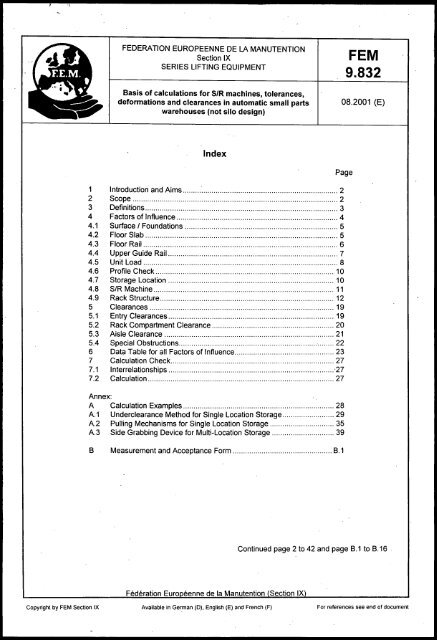
FEDERATION EUROPEENNE DE LA MANUTENTIONSection IXSERIES LIFTING EQUIPMENTBasis of calculations for SIR machines, tolerances,deformations and clearances in automatic small partswarehouses (not silo design)<strong>FEM</strong><strong>9.832</strong>08.2001 (E)Index1 Introduction and Aims 22 Scope 23 Definitions 34 Factors of Influence 44.1 Surface I Foundations 54.2 Floor Slab 54.3 Floor Rail 64.4 Upper Guide Rail 74.5 Unit Load 84.6 Profile Check 104.7 Storage Location 104.8 SIR Machine 114.9 Rack Structure 125 Clearances 195.1 Entry Clearances 195.2 Rack Compartment Clearance 205.3 Aisle Clearance 215.4 Special Obstructions 226 Data Table for all Factors of Influence 237 Calculation Check 277.1 Interrelationships ·277.2 Calculation 27Annex:A Calculation Examples 28A.1 Underclearance Method for Single Location Storage 29A.2 PUlling Mechanisms for Single Location Storage 35A.3 Side Grabbing Device for Multi-Location Storage 398 Measurement and Acceptance Form 8.1PageContinued page 2 to 42 and page 8.1 to 8.16Copyright by <strong>FEM</strong> Section IX Available in German (D). English (E) and French (F) For references see end of document
Page 2<strong>FEM</strong> <strong>9.832</strong> (08.2001)1 Introduction and AimsIn automatic small parts warehouses items are mainly stored by means of load carriers or load makeupaccessories, such as boxes, storage trays and cases. Storage and retrieval is automatically achievedby a Storage and Retrievel (refered to as SIR in the continuing text) machine. Load handling devicesoperate with lift, pull or grabbing mechanisms. The racks are designed as single or multi-locationsystems. Their functionality depends on a number of system components. The interrelation of tolerancesand deformations during operation requires sufficient clearance between moving loads or unitloads and fixed system components.The aim of this document is to show the relation of the individual system components in respect oftolerances and deformations. Permissible practical tolerances and deformations shall be listed for typicalsystem solutions. The aim is that the values for individual system components will result in clearlydefined levels of responsibility in the event of interface problems. .Due to the tolerances and deformations quantified in this document as well as the additional data fortolerances, wear and deformation of the SIR machine and the load make-up accessories, calculationsfor clearances and entry clearances must be made. The method used is described in section 7.The aim of this document is to determine the admissible deformations and tolerances in order to optimisethe factors relating to the economical dimensioning, manufacturing and assembly required for thesafe functioning of the overall system.2 ScopeThis document applies to automatic small parts warehouses (not silo design) with SIR machines whichtravel on a floor mounted rail and are stabilized by an upper guide rail. The storage locations in therack must be filled as evenly as possible (random storage).If there is to be a deviation from this guideline in a specific instance, clear arrangements must be madeand evidence of functionality of the overall system in any given operating system produced, takingnormal wear into account.
Page 3<strong>FEM</strong> <strong>9.832</strong> (08.2001)3 DefinitionsCoordinate positioning: Positioning of the SIR machine using global coordinates.Positioning via the Teach-in Process: Teach-in processes rely on calculating the position coordinatesby means of an initial control of all storage locations. The actual coordinates calculated are storedin the control system and can be reproduced. Through permanent control points the system can monitorand correct itself where possible. Depending on the warehouse configuration the Teach-inProcess can require considerable effort in calculating the individual coordinates.Location fine positioning: Basic positioning of the SIR machine using global coordinates, followed byrack fine positioning via additional sensors for the X andlor Y coordinates. The greater accuracy thisachieves is accompanied by a loss in performance. .System level: Plane without tolerances in XY direction, XZ direction and YZ direction, defined by clearlymarked points or straight lines.Tolerance: The permissiblle maximum deviation from nominal dimension, resulting from manufactureand assembly.Deformation: Deviation from the basic position due to the effect of forces.Clearance: The required nominal distance between fixed and moving parts and which, all individualtolerances and deformations considered, prevent collisions.Entry Clearance: Clearance between the load handling device and the load make-up accessory orrack structure.Rack compartment clearance: Clearance between respective unit loads and the rack structure.Aisle clearance: Clearance between the outer most edge of the SIR machine and the outer most edgeof the rack or the unit load and clearances at the rear of the stored unit load.System axes: A fixed straight line between 2 points in the X direction (aisle length direction), Y direction(aisle vertical direction) and Z direction (aisle lateral direction).Auxiliary level: Vertical or horizontal level without tolerances.
Page 4<strong>FEM</strong> <strong>9.832</strong> (08.2001)4 Factors of InfluenceA common height plane as well as common horizontal axes shall normally be defined for all componentsby the persons responsible for the construction. These shall be marked clearly and permanently,and shall act as reference points for the project-related datum planes and axes.When calculating the internal measurements of the building the negative effects of deformations andtolerances must be taken into account.Persons responsible for the construction must be able to demonstrate its suitability for use and thusdefine the conditions (forces, tolerance, admissible deformations and clearances).The constructors and sub-contractors shall ensure that individual components (e.g. floor slabs, racks,SIR machines) have sufficient capacity for the agreed loads and maintain the defined tolerances anddeformations.Tolerances and possible deformations will result from the following operating components of an automaticsmall parts warehouse:- surface/foundations behaviour under load- floor slab (manufacturing accuracy and behaviour under load)- floor rail- guide rail- load make-up accessories incl. load- profile check- storage location- SIR machine- rack structureIn contrast to high bay storage where pallets are mainly used, automatic small parts stores are characterisedby a wide range of solutions for load handling devices on SIR machines and load make-upaccessories. The following types of load handling device can be used:I. Telescopic tables (used with lifting mechanism)11. Mechanical insertion/extraction (pulling device) at the front of the load make up accessoryIll. Lateral grabbing / pushing devicesIV. Belt or conveyor pulling devicesV. All other types: All requirements must be agreed by the contract parties..Plastic containers, metal containers, trays, rigid plattens (e.g. wooden plattens), cardboard boxes etc.can be used as unit loads or load make-up accessories. As a rule, any given load make-up accessorywill require a particular load handling device. The properties of these system components may requiredifferent-clearances.
Page 5<strong>FEM</strong> <strong>9.832</strong> (08.2001)In the racking structure, different supporting beams are used for the loads. Typical solutions include:- lateral supporting angles on beams between each load make-up accessory (single location storage);- beams with support bearers embedded, Le. several loads between the stands (multi-location storage).The SIR machines can be fitted with different positioning control systems. Depending on the system,the following may be used:- pure coordinate positioning- location fine positioning- positioning via Teach-in processin X and Y directionsin X and/or Y directionNOTE: The selection of the location system (e.g. location fine positioning, Teach-in Process) willgreatly affect the clearances/entry clearances, pepending on the positioning system certain factorsof influence will not come into play (or at least to a much lesser extent) when calculating theclearances/entry clearances.4.1 Surface I FoundationsIt is assumed that the foundations for the length of the entire floor slab are the same.This is the responsibility of the constructing owner or civil engineer.4.2 Floor SlabThere are two types of floor slaba) Rigid floor slabs which lie fully flat on the surface.b) Deflection-resistant floor slabs which lie on supports or against walls, such as ceilings in buildingsor floor slabs on piles.The manufacturing tolerances listed in section 4.2.1 (warping, sloping, uneveness) apply to floor slabs.For type b) slabs, depending on each case, specific agreement must be reached relating primarily tothe behaviour of the slab in the unladen state and under increasing load condition during the filling ofthe store. If necessary, instructions on how to fill the warehouse should be drawn up.The constructing owner or civil engineer is responsible for the capacity, rigidity and flatness of the floorslab.4.2.1 Floor slab manufacturing toleranceManufacturing tolerance is the flatness of the surface on which the rack structure and the floor rail areto be assembled. The following values must be maintained when the floor slab is not under load:The following admissible tolerances result from a horizontal auxiliary plane:- up to 50 m floor slab length: ± 10 mm- over 50 m floor slab length: ± 15 mmWh~re packing plates are used under the base plates of the rack uprights, any slope of the floor slab inthe area of the rack upright feet must not lead to eccentric loading of the packing plates. The concretesurface must be flat.
Page 6<strong>FEM</strong> <strong>9.832</strong> (08.2001)4.2.2 Vertical deformations of the floor slab I sub-structure under loadThese deformations (e.g. adaptation of the floor slab to the settlement of the foundations, piles and/orsupports, permanent deformation) can result in additional stresses and inclination from the vertical ofthe rack structure and the SIR machines. These are noted here only from a qualitatve point of view.Where certain types of surface and/or floor slab conditions exist it is, nevertheless, possible for deformationsto such an extent (often to be measured in cms) to occur that they merit consideration whenassessing clearances and additional stresses. If necessary, special design features should be implemented.All the following considerations are based on a quasi-rigid floor slab for all storage component designsunless specific information is provided by the civil engineer or client.A floor slab is quasi-rigid if the following vertical deformations are not exceeded:- overall vertical deformation:1/3000 of the total storage length1/3000 of the total storage width- local vertical deformations:112500 over distances up to I = 3 m in comparison to the reference plane in the X and Z directionsin the rack area. I is the frame depth and/or width for stiffening towers.The short-term and long-term behaviour of the floor slab/sub-structure must be taken into accountwhen assessing these deformations.4.3 Floor Rail4.3.1 Type of floor railThe sizing and selection of the type of floor rail and its method of fixing and its frequency is the responsibilityof SIR machine manufacturer in association with the rail supplier and the engineer responsiblefor the floor slab.NOTE: If the travel rail is installed after assembling the rack system, its lateral and vertical positioningshould match the rack system axes.The floor running rail positioning tolerance demands must be taken into account when selecting the railprofile (manufacturing tolerances for certain profiles may exceed the positioning tolerances).The travel performance of the SIR machine can be influenced by any uneveness of the rail around therunning surface and the lateral guides as well as by the manufacturing accuracy. The surface must belevel in this area, Le. without pitting (rust, holes etc.).4.3.2 Tolerances of the floor rail in the Z directionT19: Alignmen accuracy of the floor rail in relation to a tolerance-free, vertical datum plane which mustrun parallel to the rack datum plane measured on the bearing surface of the guide rollers.T24: Installation tolerance of the floor rail in relation to a tolerance-free, vertical datum plane whichmust run parallel to the rack datum plane measured on the bearing surface of the guide rollers.Any variations of alignment at the joints of the guide roller running surface must be ground flat. Flatnessof the rail and the joint over a measured length of 200 mm must be ::; 0.5 mm.Figures are given in chapter 6.
Page 7<strong>FEM</strong> <strong>9.832</strong> (08.2001)4.3.3 Tolerances of the floor rail in the V-directionT21: Heigh tolerances of the floor rail head in the vertical direction, in relation to a tolerance-free, horizontaldatum plane.Figures are given in chapter 6.Any variations of levelness at the rail joints of the wheel running surface must be ground flat. Flatnessof the rail and the joint over a measured length of 100 mm must be:;;; 0.1 mm.4.4 Upper Guide RailMeasured length 20 m'"+.-t::::l. -0-0-'8-. -a-. -B. ---EJ -0-- CD'--- aisle'----- Tolerance field of the axisNote: permissable extremes-4"X.1tIEKey:
Page 8<strong>FEM</strong> <strong>9.832</strong> (08.2001)4.4.1 The positon of the longitudinal axis of the upper guide rail may not exceed the tolerances in relationto the mean of the centrelines of the top of the rack uprights along the aisle by ± 2 mm over ameasured length of 20 m (see figure 1).4.4.2 In the area of the guide rollers the horizontal deviation of the upper guide rail from its longitudinalaxis (without load) shall not exceed ± 2 mm (see figure 1). Over a measured length of 2 m the horizontaldeviation must lie within ± 1 mm.4.4.3 Any variations in rail profile at joints in the running area of guide rollers over a length of 200 mmshall be ground flat. Flatness in a measured length of 200 mm shall be ~ 1 mm.4.4.4 There shall be no rolling inscriptions on the running surfaces.4.4.5 The maximum lateral deformation (sagging and twisting) in the area of the guide rollers due to thereaction forces of the SIR machine between two fixing positions shall not exceed 3 mm (V11).4.4.6 The lower edge of the guide rail shall not exceed the tolerance field +5/-2 mm (T22) in comparisonto a tolerance-free datum plane when the racking is unloaded (see figure 3).4.4.7 The sizing and selection of the type of guide rail and the method of fixing is the responsibility ofthe SIR machine manufacturer in conjunction with the supplier of the upper gUide rail, (e.g. racksupplier).The high demands on the positioning tolerances of the upper guide rail must be taken into accountwhen selecting the guide rail profile (manufacturing tolerances for certain profiles may be greater thanthe positioning tolerances).4.5 Unit Load4.5.1 Load make-up accessoriesDue to the number of different load make-up accessories or unit loads, it is impossible to giveguidelines for tolerances and deformations.Qualitatively, reference should be made e.g. to the following:- deformation of the 4 sides of load make-up accessories (e.g. boxes, containers) when filling themwith loose items- sagging of the load make-up accessory or base when loaded- squarness of the base of the load make-up accessory- squarness of the side walls to the base of the load make-up accessory- additional deformations during lengthy storage periods- moulding burrs and deposits or uneveness from manufacture of plastic containers- protruding or engraved text- damage or wear resulting from use.The SIR machine manufacturer, rack manufacturer and user shall agree on the type of load make-upaccessory, its stability and quality. In the absence of other information, it is assumed that the edges ofthe load make-up accessory are resistant to bending, although the base is not specified as having tobe resistant to warping.
Page 9<strong>FEM</strong> <strong>9.832</strong> (08.2001)4.5.2 LoadingIf due to physical characteristics or operational requirements it is not possible to ensure that the load iswithin the parameters of the load make-up accessory (length, width, height), these factors must betaken into consideration and the loads passed through a profile check (see 4.6).The SIR machine manufacturer, rack manufacturer and user shall agree on the position of the loadcentre of gravity. In particular, attention must be given to fluids or sliding loads which are critical interms of stability.4.5.3 Guidance into the apertureIf the clearances from the tolerance calculations are not obtained, bevels or radii on the rack uprights,load supports and load make-up accessories can allow the input and output of loads at the storageapertures under certain conditions. The main conditions for this are:- a securely fixed load support profile member or at the least a strong positive connection betweenthe load handling device and the load make-up accessory. Any tilt movement on the part of the loadmake-up accessory must be taken into account.- bevels at a shallow angle of slope, so that the load make-up accessory does not move in an uncontrolledmanner or becomes separated from the load handling device on impact.- sufficiently large radii to act as guidance at an aperature entrance.- that the friction coefficients between the materials used allow positive sliding into the apertures.- no jamming can occur due to the twisting of the load on the load handling device when storing andretrieving.The extent to which these influences shall be taken into account when calculating the clearance issolely the responsibility of the SIR machine manufacturer who is responsible for operational safety.The rack manufacturer shall be informed of the forces which are derived from this decision.Figure 2 shows a recommendation for the calculation of slopes and radii for the clearances.It is recommended that a permissible impact point is selected at about 2/3rds of the bevel "e". Thebevel angle should not exceed a maximum of 30°.Q)zFigure 2: Entry gUidance (side and height)
Page 10<strong>FEM</strong> <strong>9.832</strong> (08.2001)4.5.4 Friction between the load make-up accessory and supporting profile in the rackIn all systems where the load make-up accessory slides, frictional forces occur between the load supportsurfaces in the rack and the load make-up accessory. By appropriate material selection {to beascertained by testing) frictional pairings and thus the frictional coefficient can be determined. It ispreferable to keep these coefficients as low as possible to limit forces and deformations. Painted surfacesand plastics require particular attention. It should also be borne in mind that the frictional coefficientcan change in certain conditions (e.g. frost, plastic packaging).It is important to note that the transition from static friction to sliding friction cause impacts which canlead to vibrations of the SIR machine and the racking structure.Rack vibrations can be ignored when calculating clearances in detail.4.6 Profile CheckProfile checking may be necessary to monitor the height, width and length.In general, devices with photocells measure the profiles with the following tolerances:- height: ± 2 mm- width: ± 3 mm per side- length: ±3mm per side This may be increased for checking the load whilst moving.- base: ±2mmThe lowest tolerance level should be the maximum contractually stipulated load dimension.4.7 Storage locationThe unit load shall be positioned at the storage location with the following tolerances except when positioningcan take place on the machine:where:Table 1Load handling device In X direction In Z directionType I ±2mm ±3mmType II,III,IV±5mmLL ~ 500 mm: ± 1 % from LLLL > 500 mm: ± 5 mmLL = Length of the load make-up accessory in the Z direction
Page 11<strong>FEM</strong> <strong>9.832</strong> (08.2001)4.8 SIR machineThe sum of the tolerances in the X, Y and Z directions caused by the SIR machine are considered insections 4.8.1 to 4.8.3.Due to considerable differences between different manufacturers' SIR machines in terms of dimensions,rigidity and other design features, this data cannot be specified within these rules. In each particularcase this data shall be specified by the SIR machine manufacturer. On the basis of this data, theSIR machine manufacturer and/or the person responsible for the system shall check the overall tolerancesin order to ensure the functioning of the system.The SIR machine tolerances used in the calcuation examples (see Annex A) can only be regarded asexamples to demonstrate the effects tolerances have on the overall system.4.8.1 System tolerances due to the SIR machineClearances can be influenced e.g. by the following:- tolerances for the mast or the lifting carriage guides on the mast- lifting carriage gUide play- load handling device tolerances- play in the Z direction between the track and guide rollers in respect of the travel or guide rail- mechanical wear4.8.2 Elastic DeformationDue to alternating load effects when retrieving and depositing load units, components such as themast, lifting carriage, and load handling device are subject to deformation which is ofimportance forfork entry and rack compartment clearances and need to be taken into account when determining the.clearances.4.8.3 Positioning TolerancesThe positioning accuracy in the X, Y and Z directions is affected e.g. by the following factors of influence:- positioning system and motor control- positioning speed- delay period of the control system- brake application delay- braking distance differences due to wear, temperature and changes of the coefficient of friction- backlash in the drive units- approach to destinations from either direction- switching accuracy (e.g. hysteresis) of the positioning sensors (switches, photocells, proximity switches)- deviation of an incremental transmitter system from the absolute dimensions- When using positioning markers (control cams, reflective tape, inductive switches flags etc.) theseshall be fitted to a tolerance of ± 1 mm (T23), relative to their nominal location.In case of re-depositing of load units without an additional centering addition of positioning tolerancesshall be taken intoaccount.· .
Page 12<strong>FEM</strong> <strong>9.832</strong> (08.2001)4.9 Rack structureThe following information is applicable for rack structures in accordance with figure 3.srst~"l"~T= " F'1= ':::> ==::-,~ --~11 I II I ['I 1 I I II 1111 I I I1 ~Top of guide ranIJl=:--t It-t _R.ck-~1!!!'! levelIH I~ ~'" U li I-IT'\:I:I-11 l-t f I1IT'\'"Hl-Height refe(penNnent~;n~:rt~~tI1 11 11D11 11'--- rTop of erom RoRJ..~NL I-~~T32I T29 T29zFigure 3: Rack structure (example of single location storage)All the following details refer to free standing rack structures.The load make-up accessories are stored on supporting profiles, e.g. supporting angles as illustratedin Figures 4 and 5.A minimum support width of 5 mm must be maintained, taking into account the tolerances of the rackand the load make-up accessory.
Page 13<strong>FEM</strong> <strong>9.832</strong> (08.2001)Detail ALf'l~>incl. toleranzof load make-up accessoryFigure 4: Deformation of the support profile/..~A-A'~-.-'JAy II-- ----:D:...Lz_incl. toleranzof load make-up accessoryFigure 5: Deformation of the support profile e.g. twin-depth single location storage
Page 14<strong>FEM</strong> <strong>9.832</strong> (08.2001)4.9.1 Manufacturing and erection tolerances in the unloaded condition4.9.1.1 Dimensions in the X directionIn the X direction the following tolerances shall be considered due to manufacturing and assembly ofthe rack (see figures 3 and 6) for:- T25: deviation of the upright axis relative to a vertical datum- T26: offset ofthe upright feet on the left and right-hand sides of the aisle- T27: upright frame at right-angles to the aisle axis- pre-bending of the upright (contained in T28)- T28: sum of tolerances of T25, T26, pre-bending and T27- T29: tolerance of the rack length L- T30: tolerance of the rack entry width for the load make-up accessory- T31: tolerance of the rack entry width for the load handling device- T32: tolerance of the distance from the front upright axis to the vertical system planeFigures are given in chapter 6.support level....:-..;::=-.----4 1000--.-- . -vFigure 6: View of rack aperture
Page 15<strong>FEM</strong> <strong>9.832</strong> (08.2001)4.9.1.2 Dimensions in the Y directionThe rack system plane is specified by the rack manufacturer. Ideally, this plane should be half the rackheight or a height above a joint.In the Y direction the following tolerances shall be considered due to manufacturing and assembly ofthe rack (see figures 3 and 7):- T33: level tolerance of the supporting beams facing the aisle at each levelT34: difference in height between the front and rear supporting beams in single-depth single locationstorageT35: distance tolerance for two adjacent planesT36: tolerance of the distance from the lowest to the highest support levelsT37: tolerance of supporting beam horizontal.Figures are given in chapter 6.-/-/v/II~~/~V./LnrY"\f-'-/'-Figure 7: Tolerances of support in Y direction
Page 16<strong>FEM</strong> <strong>9.832</strong> (08.2001)4.9.1.3 Dimensions in the Z directionIn the Z direction the following tolerances shall be considered due to manufacturing and assembly ofthe rack (see figures 3 and 8):- T38: deviation of the front upright axis from a vertical- T39: upright foot deviation from the system axis in the X direction per aisle- T40: pre-bending of the unloaded upright frame- T41: sum of the tolerances of T38, T39 and T40- T42: tolerance of the back stop to the front edge of the support- T43: tolerance of the position of the rear obstructing edge connected to the rack (e.g. fences,sheets with trapezoidal corrugations and rigidity design)Figures are given in chapter 6.T43Ii!IIIFIiiii!IiiiiI(1JVIro" o(1JcL(1J.....c(1JuIT42II~Figure 8: Rack end elevation
Page 17<strong>FEM</strong> <strong>9.832</strong> (08.2001)4.9.2 Deformations due to forcesDeformation of the racking can occur due to the following:- the loads stored- frictional forces of a unit load during storage or retrieval (pulling mechanism)- additional load forces resulting from the tilting of the rack structure during erection·- reactional forces of the SIR machine on the guide rail in the following situations:a) during travelb) docking (directly prior to making contact with the load make-up accessory)c) Storage I retrieval input/output of the racking- temperature changes- transfer of forces from neighbouring aisles or other warehouse equipment e.g. conveyorsThe following deformations must be considered on an individual basis and incorporated in the systemsupplier's overall assessment of the system's suitability:- deformation of the uprights and frames in the X, Y and Z directions- deformation of the angle supportThe deformation of the rack uprights depends on the physical properties of the material used, the rackheight, buckling lengths and loading. The rack manufacturer should be able to provide estimated deformationdata.NOTE: The following deformation data can used as a guideline:Table 2Rack height (m)Uppermost rack deformation (mm)Steel quality S235Steel quality S3556 1 to 1.5 1.5 to 2.510 1.5 to 2.5 2.5 to 416 2.5 to 4.5 4 to 6.520 3.5 to 5 5 to 824 4 to 6 6.to 10In order to demonstrate functionality (deformation) in multi-aisle stores, the calculation must only bemade with the force of a single SIR machine at the same X location. In general, the least favourableloading cases are relevant.Unless otherwise agreed it is assumed that the loads in the rack are evenly distributed, Le. no concentrationof loads next to empty racks. In particular, when filling the warehouse for the first time, it has tobe ensured that goods are stored in horizontal layers starting from the lowest level and working upwards.This can also ensure that the rack deformation is taken into account when setting the positioningmarkers.
Page 18<strong>FEM</strong> <strong>9.832</strong> (08.2001)4.9.2.1 Deformation values for uprights andl or upright frame deformationThe following uprights or upright frame deformation must be considered:- V13: side displacement of the highest point of the upright frame during operation due to externalforces and payloadsV17: deformation of uprights at the highest support plane- V18: side displacement of the highest point of the upright frame diagonal to the aisle during operationdue to external forces and payloads (calculation basis for force-acting: appr. 3 m behind thefirst upright inside the racking). In the furthest operating position the deflection must not be morethan twice the value as given in table 3.NOTE: It should be ensured by the use of horizontal bracing at the top of the uprights that the movementon both sides of the aisle is equal and in the same direction.4.9.2.2 Deformation of the supporting angle with the load in the storage positionThe following supporting angle deformation must be considered (see figure 4,5, and 9):- V14: deformation of the supporting beam with tension width I for multi-location storage- V15: deformation of the supporting angle flange with a 100 % non-centrally arranged load aroundthe support for single location storage- V16: vertical lowering of the supporting beams with a 100 % non-centrally arranged load due tosagging, torsion and local bending of the profileThere should be no residual deformation from the entry angle due to the load if the load is positioned toits max. eccentricity in respect of the supporting angle.Figure 9: Deformation of the supporting beam in a multi-location warehouse4.9.2.3 Deformation and loading on the supporting angle during storage and retrievalWhen using the load handling device Type 11 (mechanical pulling mechanism) and in general Type III(lateral grabbing I pushing mechanisms), maximum forces for a unit load in the Y direction occur, dependingon tolerances when inserting and removing the load make-up accessory at the aisle side endsof the supporting angles.The supporting angles and their attachments to the aisle side upright must bear all the load forces of allthe transferred unit loads without suffering permanent deformation. The deformation listed under4.9.2.2. may be exceeded in this case.
Page 19<strong>FEM</strong> <strong>9.832</strong> (08.2001)5 ClearancesAll clearances relate to a tolerance-free, unloaded system.5.1 Entry clearancesEntry clearances are the clearances between the load handling device and the unit load, or betweenthe load handling device and the rack. The respective largest entry cross-section of the load handlingdevices should be considered. Due to the mast deformation on single mast machines the clearancesfor the side facing and the side facing away from the mast (single mast machines) shall be calculatedseparately.Key:X1 entry dimension between the load handling device and the rack obstructing edgeX2 entry dimension between the load handling device and the rack obstructing edgeX3.1 clearance between the unit load and the rackX3.2 clearance between the unit load and the rackY1 entry dimension between the bottom edge of the load handling device and the top edge of theunit loadY2 entry dimension between top edge of the load handling device and the bottom edge of the unitloadY3 clearance between top edge of the unit load and the bar of the rack bracingY4 clearance between the bottom edge of the unit load and the top edge of the supporting angleYS clearance between the top edge of the unit load and the bottom edge of the supporting angleFigure 10: Entry dimensions and clearances for underclearance method
Page 20<strong>FEM</strong> <strong>9.832</strong> (08.2001)5.2 Rack compartment clearanceThe rack compartment clearance is the minimum distance between the unit loads and the uprights,between the unit loads with reference to each other as well as between the top edge of the stored unitload and the rack structure or obstructing edge (e.g. sprinkler). Due to the mast deformation on singlemast machines the clearances for the side facing and the side facing away from the mast shall becalculated separately.1'"1',~I)':1I-~! \~IX3.1 X3.2~X3.2p.-P--t,../ 1/Key:X3.1 clearance between the unit load and the rack obstructing edgeX3.2 clearance between the unit load and the rack obstructing edgeY3 clearance between the top edge of the load and the rack's longitudinal bar, or the supportingbeam above itY4 clearance between the bottom edge of the unit load and the top edge of the supportingbeamYS clearance between the top edge of the unit load and the bottom edge of the supportingbeam .Figure 11: Clearances for pulling mechanism
Page 21<strong>FEM</strong> <strong>9.832</strong> (08.2001).--I~I~ ~~ .~~I.I~~~~......~i ;;~~ ~ 17:~ ~ I-I-~ ~~ ~ ~ lI:~ '-- H;:1....... -BJ.. M:.L M:.L Xl.2 "-Bd.- to-- t-B:! - t-B:! - 2UKey:X1.1 entry clearance between load handling device and rack structureX1.2 entry clearance between load handling device and load make-up accessoriesX2.1 entry clearance between load handling device and load make-up accessoriesX2.2 entry clearance between load handling device and rack structureY1 entry clearance between the bottom edge of the load handling device and the top edge of thesupporting beamY2 entry clearance between the top edge of the load handling device and the bottom edge of thesupporting beamY3 clearance between the top edge of the unit load and the bottom edge of the supporting beamY4 clearance between the bottom edge of the unit load and the top edge of the supporting beamYS clearance between the top edge of the unit load and the bottom edge of the supporting beamFigure 12: Clearances for lateral pull mechanisms, multi location storage5.3 Aisle clearanceThe following aisle clearances should be checked (see figure 13):- Z1.1 between the unit load and the front obstruction (e.g. front bar, downpipe, back stops, rackbrace design, etc.)- Z1.2 between the unit load and the inside racks of the rack structure (e.g. rack brace design,sprinkler)-Z2.1-Z2.2- Z3.1- Z3.2- Z4.1-Z4.2between the outer most point of the lifting carriage or the unit load on the lifting carriage andthe nominal position of the stored load or the rack obstructions if load is stored to the back;rack edge.as above, centre rack side.between fixed obstructions on the SIR machine (e. g. lifting mechanisms, platforms etc.) andthe stored load or the rack obstruction; rack edge.as above, centre rack side.between the back stop and rear edge of the unit load; rack edge.as above, centre rack side.
Page 22<strong>FEM</strong> <strong>9.832</strong> (08.2001)Z1.2/~rlI II r'f::-'_.-71 ~ "-"- t::- v I............ / Z2.2 I Z2.1............ / 1, ,t-- i -. '/ ............/ .................. In>K.,lU~'r--:- V ' fJ--JZ4.2 ",III~,.., I...IhoistItZ3.2.. I... ILLrrIIImastI Z3.1I1-I~ 1'-e--I !-18~Z4.1Figure 13: Aisle clearance5.4 Special Obstructions, The following shall be considered in the planning phase and in particular when calculating clearances:- arrangement of sprinklers and smoke alarm systems- utility installations (cables, lighting, routing, pipes etc.)- minimum distances (e.g. to the sprinkler nozzles)- variation of the profile dimensions depending on the rack system- protruding components (screw heads, supports, transmitters etc.)- modification of unstable loads during storage
Page 23<strong>FEM</strong> <strong>9.832</strong> (08.2001)6 Data Table for all Factors of Influence(T: Tolerance field. V: Deformation value)Table 3 (continued)Rack typeNo.Factor of influence/Relating toMulti-Location Sy-stemSingle Location SystemStore HeightStore HeightFig.>12 m >12 m~12m ~24 m ~ 12 m ~24 mT1T2T3Load and rofile check 4.6Tolerance of load width (measurement accuracy)Tolerance of load length (measurement accuracy)Tolerance of load height (measurement accurac±3er side±3er side±2T4T5in X directionV1T6T7T8T9T10T11T12T13T14T15T16T17T18V2V3SIR machine 4.8Positionin accurac in X directionPositionin accurac in Y directionPositioning accuracy of load handling devicein Z directionPositioning accuracy of load handling device centerinMast manufacturing accuracy in X direction, e.g.ali nment, strai htness of vertical uide railMast manufacturin accurac in Z directionHorizontal twisting of the lifting carriage due tomast uide tolerancesInclination of the load handling device top edge inX direction in relation to the horizontal datumInclination of the load handling device top edge inZ direction, with reference to the horizontal datum,resulting from erection tolerances, roller clearances,floor and u er uide rail tolerancesSide uide roller la ,bottomErection accuracy of the height positioning markerswith reference to the rack corn artment levelsLoad handling device deflection, unloaded (rollerclearance and wearWheel and floor rail wearMast deflection resulting from oscillations inX directionMast deformation in X direction at the top racka erture level load transfer deformation"continued"
Page 24<strong>FEM</strong> <strong>9.832</strong> (08.2001)Table 3 (continued)Rack typeNo.Factor of influence/Relating toMulti-Location Sy-stemSingle Location SystemStore HeightStore Height>12 m >12 m~12m~24m ~24mFig.V4V5V6V7V8VgV10Load deflection in Z direction due to distortion ofthe mast, lifting carriage and load handling devicedue to static load moments and oscillation (deendson the hei ht of the unit loadLoad oscillation in Z direction during travel due tothe bendin and torsional oscillations of the mastDisplacement of end of the load handling device inX direction during load handling device extensiondue to liftin carria e torsionDeformation of end of the load handling deviceunder nominal load with max. load handling deviceextension due to load handlin device deformationDeformation of end of the load handling deviceunder nominal load with max. load handling deviceextension due to lifting carriage and mast deformationDisplacement of end of the load handling device inXdirection during load handling device extensiondue to mast torsionExtension of sus ension element due toa loadData is set by the SIR manufacturer for eachproject. Annex A contains calculation examles.Aisle E ui mentT19 Ali nment accurac of the floor rail 4.3.2 ±2 ±2 ±2 ±2Alignment accuracy of the upper guide rail axis andT20horizontal deviations of the guide rail relative to this ±2; ±2; ±2; ±2;axis; measured length of 20 m; region of the guide ± 2/± 1 ± 2/± 1 ± 2/± 1 ± 21± 1rollers/measured len th of 2 m 4.4.1; 4.4.2T21Height tolerance of the floor rail head; totallen thlwheelbase 4.3.3± 1.5/± 0.5 ± 1.5/± 0.5 ± 1.5/± 0.5 ± 1.5/± 0.5T22 Hei ht tolerance of the u er uide rail 4.4.6 +5/-2 +5/-2 +5/-2 +5/-2 3T23Installation accuracy of the positioning marker inthe X direction 4.8.3±1 ±1 ±1 ±1Installation tolerance of the floor rail in Z directionT24 in relation to the vertical plane datum; total ±21± 1 ± 21± 1 ±2/± 1 ± 2/± 1len thlwheelbase 4.3.2V11Deflection of the upper guide rail in Z direction withthe load extended 4.4.53 3 3 3V12 Deformation of the floor rail in Y directionData is set by the SIR manufacturer for eachproject. Annex A contains calculation examles..continued"
Page 25<strong>FEM</strong> <strong>9.832</strong> (08.2001)Table 3 (continued)No.Factor of Influence/Relatlng toRack typeSingle Location Sys- Multi-Location Systemtem Fig.Store HeightStore Height&12m>12m>12m&12m:!>24ms24mRack structure in X direction (4.9.1.1)T25 Deviation of upright axis relative to a vertical datum ±7 ±10 ±7 ±10 3T26Offset of the upright feet on the left and right-handaisle sides3 3 3 3T27 Upright frame at right-angles to the aisle axisContained Contained Contained ContainedinT~8 inT28 inT28 inT28T28Sum of tolerances of T25, T26, pre-bending andT27 max.±8 ± 12 ±8 ±12 3T29 Tolerance of the rack length L ±1%o of L ±1%0 of L ±1%o of L ±1%o of L 3T30Tolerance of the rack entry width for the loadmake-up accessory±4 ±4 ±4 ±4 6T31Tolerance of the rack entry width for the loadhandling device±4 ±4 ±4 ±4 6Side displacement of the highest point of theupright frame during operation due to externalV13 forces and payloads (4.9.2.1), with: ±4 ± H/3000 ±6 ± H/3000H = Nominal height from top edge ground to bottomedge cross barT32Tolerance of the distance from the front uprightaxis to the vertical system plane±5 ±5 ±5 ±5 3Rack structure in Y direction (4.9.1.2)T33Level tolerance of the supporting beams facing theaisle at each level±3 ±5 ±5 ±5Difference in height between the front and rearT34 supporting beams in single-depth single location ±2 ±2 ±2 ±2 7storageT35 Distance tolerance for two adjacent planes ±2 ±2 ±2 ±2 7V14deformation of the supporting beam with tension 1/375 1/3759T36width I for multi-location storage (4.9.2.2)- -max.8 max.8Tolerance of the distance from the lowest to thehighest support level, with: ± 0.5%0 ±0.5%o ± 0.5%0 ± 0.5%0H = Nominal height from top edge ground to bot- ofH ofH ofH ofHtom edge cross barT37 Tolerance of the supporting beam horizontal ± 1° ± 1° ± 1° ± 1° 6Deformation of the supporting angle flange with aV15 100 % non-centrally arranged load around the 3 3 -- - 4support for single location storage (4.9.2.2)V16V17Vertical lowering of the supporting beams with a100 % non-centrally arranged load due to sagging, 3+0/150 3+0/150 8+D/200 8+D/200torsion and local bending of the profile (4.9.2.2), but s10 but s10 buts15 but s155with: 0 = Frame depthDeformation of uprights at the highest support See See See Seeplane (4.9.2.1) table 2 table 2 table 2 table 2.continued"3
Page 26<strong>FEM</strong> <strong>9.832</strong> (08.2001)Table 3 (concluded)No.Factor of influence/Relating to:Rack typeSingle Location Sys- Multi-Location Systemtem Fig.Store HeightStore Height&12m>12m&12 m>12m~24m ~24mRack structure in Z direction (4.9.1.3)T38 Deviation of the front upright axis from a vertical ±6 ±10 ±6 ± 10 3T39Upright foot deviation from the system axis inX direction per aisle±3 ±3 ±3 ±3 3T40 Pre-bending of the unloaded upright frameContained Contained Contained ContainedinT41 inT41 inT41 inT413T41 Sum of Tolerances of T38, T39 and T40 max. ±8 ± 12 ±8 ± 12 3T42Tolerance of the back stop to the front edge of thesupport±2 ±2 ±2 ±2 8Tolerance of the position of the rear obstructingT43 edge connected to the rack (e.g. fences, sheets ± 15 ± 15 ± 15 ±15 8with trapezoidal corrugations and rigidity design)Side displacement of the highest point of theupright frame diagonal to the aisle during operati-V18 on due to external forces and payloads (4.9.2.1), with:±4 ± H/2000 ±4 ± H/2000H = Nominal height from top edge ground to bottomedge cross barT44V19V20V21V22Construction and Miscellaneous (ignored inthe subsequent calculation examples)Dimensional constraints resulting from, e.g. fixingmaterials, sprinklers, smoke detectors, heatingpipes, electrical cables, ventilation, lighting, bracketsof hook-in type beams and rainwater pipesetc.Dimensional changes of the load during storageAdditional deformation of the load make-up accessoryDeformation and deflection of the floor slab resultingin the inclination of the SIR machine and therackingBuilding deformations due to wind and roof stresses
Page 27<strong>FEM</strong> <strong>9.832</strong> (08.2001)7 Calculation Check7.1 InterrelationshipsA verifying calculation should be carried out by the person responsible for the system in each individualcase to determine that the defined clearances, taking into account known tolerances and deformations,will allow the system to function reliably.When considering the individual clearances, the individual allowable tolerances and deformations willdepend on the positioning process and the load handling device used. Calculation examples are givenin Annex A.Certain tolerances and in particular deformations occurring in the same direction can be reduced byadjusting the SIR machine, e.g. positioning the SIR machine mast in the X direction parallel to the rackor setting the upper Y positioning markers deeper after part-filling the store and taking account of anycompression of the uprights.7.2 CalculationThe worst case condition occurs with all tolerances and deformations at a maximum value and in theleast favourable direction. To optimise the overall system, the suppliers (SIR machine, aisle equipmentand rack) ensure that the overall tolerances are at the worst, 70% of the total tolerances according tothe worst case condition. The overall tolerances as per the worst case method are the sum of the tolerancesto be considered in the clearances and entry clearances calculation in accordance withchapter 6. The reduced rack/entry clearances from equation 1 can be used to design the system.f real =0.70 L Ti max + L Vi max(1 )where:Timax: Sum of max. admissible individual tolerances of a single component (data from chapter 6)Vimax:Sum of max deformations from calculations and data within a component
·Page 28<strong>FEM</strong> <strong>9.832</strong> (08.2001)AnnexACalculation ExamplesThe following examples can be used to explain the interrelationships with numerical values.As demonstrated in 4.8, the values for the SIR machines are only examples which show theeffects on the overall system. These values must not be used under any circumstance for tolerancecalculations. The actual values must be calculated by the equipment manufacturer or theperson responsible for the system.The following possible influencing factors are ignored in the calculation examples:- uneven wheel wear- uneven rail deformation due to different loads on each wheels- residual oscillation amplitudes after settling period- uneven ground settings- floor slab deformation greater than described in chapter 4.2.2- deformation of the load after passing the profile checkAll dimensions in the tables given are given in mm.Used abbreviation:LHD: Load handling device
Page 29<strong>FEM</strong> <strong>9.832</strong> (08.2001)Annex A.1Underclearance Method for Single Location StorageTable A.i.i: Entry clearances Xi and X2 between LHD and rack structurePositioning Coordinates Teach Rack finesystem In pos.Store Height 10 m 20m 20m 20mFactor of influence Significance No.:SIR machine Positionina accuracy T6 2.0 2.0 2.0 2.0Mast manufacturing accuracy T10 1.0 1.0 0.0 0.0Liftina carriaae twistina due to mast auide T12 1.0 1.0 0.0 0.0Side guide roller clearance T15 1.0 1.0 1.0 1.0Upper mast deformation due to load transfer V3 4.0 10.0 10.0 10.0Lifting carriage twisting due to load transfer V6 1.0 1.0 1.0 1.0Mast deflection due to oscillation V2 1.0 2.0 2.0 2.0Deflection from mast torsion V9 1.0 3.0 3.0 3.0Installation accuracy of the positionina markers T23 1.0 1.0 0.0 0.0Aisle equipment Alignment accuracy of the floor rail T19 1.0 1.0 0.0 0.0HeiQht tolerance of the floor rail head T21 3.0 6.0 0.0 0.0Racking Upriaht tolerance field T28 8.0 12.0 0.0 0.0Tolerance of the rack entry width T31 4.0 4.0 4.0 4.0Deformation due to payload V13 4.0 6.5 6.5 0.0Entry dimensionEntry dimension at 70% toleranceX1X2X1X233.0 51.5 29.5 23.026.4 42.8 27.4 20.9Table A.1.2: Rack compartment clearances X3.1 and X3.2 between the unit load and rackstructurePositioning Coordinates Teach Rack finesystem In pos.Store Heiaht 10 m 20m 20m 20mFactor of influence Significance No.:Load make-up PositioninQ accuracY T4 2.0 2.0 2.0 2.0accessory Tolerance of load width T1 3.0 3.0 3.0 3.0SIR machine Positioning accuracy, 2x T6 4.0 4.0 4.0 4.0Mast manufacturinQ accuracy T10 1.0 1.0 0.0 0.0Lifting carriage twisting due to mast guide, 2x T12 2.0 2.0 0.0 0.0Side auide roller clearance, 2x T15 2.0 2.0 1.0 1.0UDPer mast deformation due to load transfer V3 4.0 10.0 10.0 0.0LiftinQ carriaQe twistinQ due to load transfer V6 1.0 1.0 1.0 1.0Mast deflection due to oscillation V2 1.0 2.0 2.0 2.0Deflection from mast torsion V9 1.0 3.0 3.0 3.0Installation accuracy of the positioning markers, T23 2.0 2.0 0.0 0.02xAisle equipment Alignment accuracy of the floor rail T19 1.0 1.0 0.0 0.0HeiQht tolerance of the floor rail head T21 3.0 6.0 0.0 0.0Rack system Upright tolerance field T28 8.0 12.0 0.0 0.0Tolerance of the rack entry width T31 4.0 4.0 4.0 4.0Deformation due to payload V13 4.0 6.5 6.5 0.0Entry dimensionEntry clearance at 70% toleranceX3.1X3.2X3.1.X3.243.0 61.5 36.5 20.033.4 49.8 32.3 15.8
.Page 30<strong>FEM</strong> <strong>9.832</strong> (08.2001)Table A~1.3: Entry clearance Y1 between the top edge of the load make-up accessory and thebottom edge of the LHDFactor of influenceLoad make-upaccessoSIR machineAisle equipmentRackinSi nificanceTolerance of load heightPositioning Coordinates Teach Rack finesystem In os.Store hei ht 10m 20m 20m 20mNo.:nlaT3 2.0 2.0 2.0T7 2.0 2.0 2.0T13 1.0 1.0 1.0T14 1.0 1.0 1.0marker T16 1.0 1.0 0.0T17 2.0 2.0 2.0V12 0.0 0.0 0.0T21 1.5 1.5 0.0T33 3.0 5.0 0.0Y1 13.5 15.5 8.0Y1 9.5 10.9 5.6..Table A.1.4: Rack compartment clearance Y2 between the top edge of the LHD and the bottomedge of the load make-up accessoryPositioning Coordinates Teach Rack finesystem In os.Store Height 10 m 20m 20m 20mFactor of influence Si nificance No.: nlaLoad make-upaccessoDeformation of load make-up accessory V1 3.0 3.0 3.0SIR machine T7 2.0 2.0 2.0T13 1.0 1.0 1.0T14 1.0 1.0 1.0marker T16 1.0 1.0 0.0Aisle e ui ment T21 1.5 1.5 0.0Racking T33 3.0 5.0 0.0T34 4.0 4.0 4.0V15 3.0 3.0 3.0V17 2.0 4.0 4.0Y2 21.5 25.5 18.0Y2 17.5 20.9 15.6
Page 31<strong>FEM</strong> <strong>9.832</strong> (08.2001)Table A.1.S: Rack compartment clearance Y4 between the top edge of the support profile andthe bottom edge of the load make-up accessoryFactor of influenceSIR machineAisle equipmentRackinPositioning Coordinates Teach Rack finesystemt-:-c:---r-'::"":"'"_t-:,....:I:..:.n_+-~o:..:::s~.-IStore Height 10 m 20 m 20 m 20 mNo.:nlaT7 2.0 2.0 2.0T16 1.0 1.0 0.0T17 1.0 1.0 1.0V7 1.0 1.0 1.0V8 1.0 1.0 1.0V10 2.0 4.0 2.0T21 1.5 1.5 0.0V12 0.0 0.0 0.0T33 3.0 5.0 0.0Y4 12.5 16.5 7.0Y4 10.0 13.4 6.1Table A.1.6: Rack compartment clearance YS between the top edge of the load make-up accessoryand the bottom edge of the support profileFactor of influenceLoad make-upaccessoSIR machine. Aisle e ui mentRackingPositioning- Coordinates Teach Rack finesystem In os.Store height 10 m 20m 20m 20mNo.:nlaV1 0.0 0.0 0.0T3 2.0 2.0 2.0T7 2.0 2.0 2.0marker T16 1.0 1.0 0.0T13 1.0 1.0 1.0T14 1.0 1.0 1.0T21 1.5 1.5 0·.0T33 3.0 5.0 0.0T34 4.0 4.0 4.0T35 2.0 2.0 2.0V15 3.0 3.0 3.0V17 2.0 4.0 4.0Y5 22.5 26.5 19.0Y5 17.3 20.7 15.4Table A.1.7: Distance Y3 between the top edge of the load make-up accessory and the bottomedge of the supporting profilePositioning- Coordinates Teach Rack finesystem In os.Store height 10 m 20m 20m 20mFactor of influence Si nificance No.: nlaEnt clearance Y2 21.5 25.5 18.0Ent clearance at 70% tolerance Y2 17.5 20.9 15.6Rack com artment clearance Y4 12.5 16.5 7.0Rack com artment clearance at 70% tolerance Y4 10.0 13.4 6.1Rack com artment clearance Y5 22.5 26.5 .19.0Rack com artment clearance at 70% tolerance Y5 17.3 20.7 15.4Minimum distance Y3 56.5 68.5 44.0Minimum distance at 70% tolerance Y3 44.7 54.9 37.1
Page 32<strong>FEM</strong> <strong>9.832</strong> (08.2001)Table A.1.8: Clearances Z1.1 and Z1.2 between the rear edge of the load make-up accessoryand the rack I buildingPositioning- Coordinates Teach Rack finesystem In os.Store height 10m 20m 20m 20mFactor of influence Si nificance No.: n/a n/aLoad make-up T2 3.0 3.0accesso T5 3.0 3.0SIR machine T8 3.0 3.0T10 2.0 3.0T12 1.0 2.0T15 0.0 0.0T14 1.0 1.0V4 3.0 6.0Aisle equipment T19 2.0 2.0T20 4.0 4.0V11 3.0 3.0T24 2.0 2.0Racking T41 8.0 12.0T43 15.0 15.0T44 20.0 20.0Z1.1 55.0 64.0Z1.2 50.0 59.0Z1.1 40.3 47.5Z1.2 36.8 44.0Table A.1.9: Clearances Z2.1 and Z2.2 between the aisle-side load and parts of the liftingcarriageRackingPositioning- Coordinates Teach Rack finesy'stem In os.Store height 10m 20m 20m 20mNo.: nla nlaT2 3.0 3.0T5 3.0 3.0T8 3.0 3.0T15 0.0 0.0V5 2.0 4.0T34 0.0 0.0Z2.1 11.0 13.0Z2.2 11.0 13.0Z2.1 8.3 10.3Z2.2 8.3 10.3
Page 33<strong>FEM</strong> <strong>9.832</strong> (08.2001)Table A.1.1 0: Clearances Z3.1 and Z3.2 between the aisle side load and parts of the automaticSIR machinePositioning- Coordinates Teach Rack finesystem In os.Store height 10m 20m 20m 20mFactor of influence No.: nla nlaLoad make-up T2 3.0 3.0accesso T5 3.0 3.0SIR machine T8 3.0 3.0T15 0.0 0.0V5 5.0 8.0RackingT34 0.0 0.0Z3.1 14.0 17.0Z3.2 14.0 17.0Z3.1 11.3 14.3Z3.2 11.3 14.3Table A.1.11: Clearances Z4.1 and Z4.2 between the load make-up accessory and the back stopFactor of influenceLoad make-upaccessoSIR machineAisle equipmentRackingPositioning- Coordinates Teach Rack finesystem In os.Store height 10m 20m 20m 20mNo.: nla nlaT2 3.0 3.0T5 3.0 3.0T8 3.0 3.0T11 2.0 3.0T12 1.0 1.0T15 0.0 0.0V5 5.0 8.0T19 2.0 2.0T20 4.0 4.0V11 3.0 3.0T24 2.0 2.0T34 0.0 0.0T42 2.0 2.0T41 8.0 12.0Z4.1 38.0 46.0Z4.2 38.0 46.0Z4.1 29.0 35.5Z4.2 29.0 35.5
Page 34<strong>FEM</strong> <strong>9.832</strong> (08.2001)AnnexA.2Pulling Mechanisms for Single Location StorageTable A.2.1: Rack compartment clearances X3.1 and X3.2 between the' unit load and rackstructurePositioning- Coordinates Teach Rack finesystem In pos.Store height 10 m 20m 20m 20mFactor of influence Significance No.:Load make-upaccessoryTolerance of load width T1 0.5 0.5 0.5 3.0SIR machine Positioning accuracy T6 2.0 2.0 2.0 4.0Mast manufacturing accuracy no 1.0 1.0 1.0 0.0Lifting carriage twisting due to mast guide T12 1.0 1.0 1.0 0.0Side roller guide clearance T15 1.0 1.0 1.0 1.0Upper mast deformation due to load transfer V3 4.0 10.0 10.0 0.0Lifting carriage torsion due to load change V6 1.0 1.0 1.0 1.0Mast deflection due to oscillations V2 1.0 1.0 1.0 1.0Deflection due to mast torsion V9 1.0 1.0 1.0 1.0Installation accuracy of the positioning marker T23 2.0 2.0 0.0 0.0Aisle equipment Alignment accuracy of the floor rail T19 1.0 1.0 0.0 0.0Height tolerance of the floor rail head T21 3.0 6.0 0.0 0.0Racking Upright tolerance field T28 8.0 12.0 0.0 0.0Tolerance of rack entry width T31 4.0 4.0 4.0 4.0Deformation due to pavload V13 4.0 6.5 6.5 0.0Entry clearanceX3.1X3.234.5 50.0 29.0 15.0Entry clearance at 70"10 toleranceX3.1X3.227.5 40.9 26.2 11.4Table A.2.2: Rack compartment clearance Y4 between the top edge of the supporting profileand the bottom edge of the load make-up accessoryFactor of influenceSIR machineAisle equipmentRackinPositioning- Coordinates Teach Rack finesystem In os.Store height 10m 20m 20m 20mNo.:nlaT7 2.0 2.0 2.0T16 1.0 1.0 0.0T17 1.0 1.0 1.0V8 1.0 1.0 1.0V10 2.0 4.0 2.0T21 1.5 1.5 0.0V12 0.0 0.0 0.0T33 3.0 5.0 0.0Y4 11.5 15.5 6.0Y4 9.0 12.4 5.1
Page 35<strong>FEM</strong> <strong>9.832</strong> (08.2001)Tabelle A.2.3: Rack compartment clearance VS between the top edge of the load make-upaccessory and the bottom edge of the supporting profilePositioning- Coordinates Teach Rack finesystem In pos.Store height 10 m 20m 20m 20mFactor of influence Significance No.: nlaLoad make-up Deformation of load make-up accessory V1 0.0 0.0 0.0accessory Tolerance of load height T3 2.0 2.0 2.0SIR machine Positioning accuracy T7 2.0 2.0 2.0Erection accuracy of height positioning marker T16 1.0 1.0 0.0Load handling device tilt in X direction T13 1.0 1.0 1.0Load handling device tilt in Z direction T14 . 1.0 1.0 1.0Aisle equipment Height tolerance of the floor rail head T21 1.5 1.5 0.0Racking Level tolerance of the supporting beams T33 3.0 5.0 0.0Difference in height between the front and rear T34 4.0 4.0 4.0supporting beamDistance tolerance of two adjacent planes T35 2.0 2.0 2.0Deformation of supporting angle flange V15 5.0 5.0 5.0Deformation of rack upright V17 2.0 4.0 4.0Rack compartment cleareance Y5 24.5 28.5 21.0Rack compartment clearance at 70% tolerance Y5 19.3 22.7 17.4Table A.2.4: Distance V3 between the top edge of the load make-up accessory and the bottomedge of the supporting profilePositioning- Coordinates Teach...Rack finesystem In pos.Store height 10 m 20 m 20m 20mFactor of influence Significance No.: nlaRack compartment clearance Y4 11.5 15.5 6.0Rack compartment clearance at 70% tolerance Y4 9.0 12.4 5.1Rack compartment clearance Y5 24.5 28.5 21.0Rack compartment clearance at 70% tolerance Y5 19.3 22.7 17.4Minimum distance Y3 36.0 44.0 27.0Minimum distance at 70% tolerance Y3 28.3 35.1 22.5
Page 36<strong>FEM</strong> <strong>9.832</strong> (08.2001)Table A.2.5: Clearances Z1.1 and Z1.2 between the rear edge of the load make-up accessoryand the rack/buildingPositioning- Coordinates Teach Rack finesystem In os.Store height 10m 20m 20m 20mFactor of influence No.: nla nlaLoad make-up T2 3.0 3.0accesso T5 3.0 3.0SIR machine T8 3.0 3.0T10 2.0 3.0T12 1.0 2.0T15 0.0 0.0T14 1.0 1.0V4 3.0 6.0Aisle equipment T19 2.0 2.0T20 4.0 4.0V11 3.0 3.0T24 2.0 2.0Racking T41 8.0 12.0T43 15.0 15.0T44 20.0 20.0Z1.1 55.0 64.0Rack centre clearance Z1.2 50.0 59.0Rack ed e clearance at 70% tolerance Z1.1 40.3 47.5Rack centre clearance at 70% tolerance Z1.2 36.8 44.0Table A.2.6: Clearances Z2.1 and Z2.2 between the aisle side load and parts of the liftingcarriagePositioning- Coordinates Teach Rack finesystem In os.Store height 10m 20m 20m 20mFactor of influence No.: nla nlaLoad make-up T2 3.0 3.0accesso T5 3.0 3.0SIR machine T8 3.0 3.0T15 0.0 0.0V5 2.0 4.0RackingT34 0.0 0.0Z2.1 11.0 13.0Z2.2 11.0 13.0Z2.1 8.3 10.3Z2.2 8.3 10.3
Page 37<strong>FEM</strong> <strong>9.832</strong> (08.2001)Table A.2.7: Clearances Z3.1 and Z3.2 between the aisle side load and parts ofthe automaticSIR machinePositioning- CoordinatessystemStore height 10m 20mFactor of influenceNo.:Load make-up T2 3.0 3.0accesso T5 3.0 3.0SIR machine T8 3.0 3.0T15 0.0 0.0V5 5.0 8.0RackingT34 0.0 0.0Z3.1 14.0 17.0Z3.2 14.0 17.0Z3.1 11.3 14.3Z3.2 11.3 14.3Table A.2.8: Clearances Z4.1 and Z4.2 between the load make-up accessory and the back stopFactor of influenceLoad make-up accessorySIR machineAisle equipmentRackingSi nificanceTolerance of load lengthPositioning- CoordinatessystemStore height 10 m 20mNo.:T2 3.0 3.0T5 3.0 3.0T8 3.0 3.0T11 2.0 3.0T12 1.0 1.0T15 0.0 0.0V5 5.0 8.0T19 2.0 2.0T20 4.0 4.0V11 3.0 3.0T24 2.0 2.0T34 0.0 0.0T42 2.0 2.0T41 8.0 12.0Z4.1 38.0 46.0Z4.2 38.0 46.0Z4.1 29.0 35.5Z4.2 29.0 35.5
Page 38<strong>FEM</strong> <strong>9.832</strong> (08.2001)Annex A.3Side Grabbing lDevice for Multi-Location StorageTable A.3.1: Entry clearances X1.1 und X2.2 between LHD and rack structurePositioning- Coordinates Teach Rack finesystem In pos.Store height 10m 20m 20m 20mFactor of influence SiQnificanceNo.:SIR machine Positioning accuracy T6 2.0 2.0 2.0 2.0Mast manufacturinQ accuracy T10 1.0 1.0 0.0 0.0LiftinQ carriaQe twistinQ due to mast Quide T12 1.0 1.0 0.0 0.0Side roller guide clearance T15 1.0 1.0 1.0 1.0Upper mast deformation due to load transfer V3 4.0 10.0 10.0 10.0LiftinQ carriaQe twistinQ due to load transfer V6 1.0 1.0 1.0 1.0Mast deflection due to oscillations V2 1.0 2.0 2.0 2.0Deflection due to mast torsion V9 1.0 3.0 3.0 3.0Installation accuracy of the positioning markers T23 1.0 1.0 0.0 0.0Aisle equipment Alignment accuracy of the floor rail T19 1.0 1.0 0.0 0.0Height tolerance of the floor rail head T21 3.0 6.0 0.0 0.0Racking Upright tolerance field T28 8.0 12.0 0.0 0.0Tolerance of the rack entry width T31 4.0 4.0 4.0 4.0Deformation due to payload V13 4.0 6.5 6.5 0.0Entry clearanceX1.1X2.233.0 51.5 29.5 23.0Entry clearance at 70"10 toleranceX1,1X2.226.4 42.8 27.4 20.9Tabelle A.3.2: Entry clearances X1.2 and X2.1 between LHD und load make-up accessoryPositioning- Coordinates Teach Rack finesystem In pos.Store height 10m 20m 20m 20mFactor of influence SignificanceNo.:SIR machine Positioning accuracy, 2x T6 4.0 4.0 4.0 4.0Mast manufacturing accuracy T10 1.0 1.0 0.0 0.0LiftinQ carriaQe twistinQ due to mast Quide T12 1.0 1.0 0.0 0.0Side guide roller clearance T15 1.0 1.0 1.0 1.0Upper mast deformation due to load transfer V3 4.0 10.0 10.0 10.0Lifting carriage twisting due to load transfer V6 1.0 1.0 1.0 1.0Mast deflection due to oscillations V2 1.0 2.0 2.0 2.0Deflection due to mast torsion Vg 1.0 3.0 3.0 3.0Installation accuracy of the positioning markers T23 1.0 1.0 0.0 0.0Aisle equipment AliQnment accuracy of the floor rail T19 1.0 1.0 0.0 0.0HeiQht tolerance of the floor rail head T21 3.0 6.0 0.0 0.0Racking Deformation due to payload V13 4.0 6.5 6.5 0.0Entry clearanceX1.2X2.123.0 37.5 27.5 21.0Entry clearance at 70"10 toleranceX1.2X2.119.4 33.0 26.0 19.5
Page 39<strong>FEM</strong> <strong>9.832</strong> (08.2001)Table A.3.3: Entry clearance Y1 between LHD and the top edge of the supporting profilePositioning- Coordinates Teach Rack finesystem In os.Store height 10m 20m 20m 20mNo.:T7 2.0 2.0 2.0T13 1.0 1.0 1.0marker T16 1.0 1.0 0.0T17 0.0 0.0 0.0T18 0.0 0.0 0.0V7 0.0 0.0 0.0V8 0.0 0.0 0.0Aisle equipment T21 1.5 1.5 0.0V12 0.5 0.5 0.0Racking T33 5.0 5.0 0.0T34 4.0 4.0 0.0Y1 15.0 15.0 3.0Y1 10.7 10.7 2.1nlaTable A.3.4: Entry clearance Y2 between LHD and bottom edge of the supporting profilePositioning- Coordinates Teach Rack finesystem In os.Store height 10 m 20m 20m 20mNo.:T7 2.0 2.0 2.0T13 1.0 1.0 1.0marker T16 1.0 1.0 0.0T17 0.0 0.0 0.0T18 0.0 0.0 0.0V7 0.0 0.0 0.0V8 0.0 0.0 0.0Aisle equipment T21 1.5 1.5 0.0V12 0.5 0.5 0.0Racking T33 5.0 5.0 0.0T34 4.0 4.0 0.0lanes T35 2.0 2.0 2.0V14 6.5 6.5 6.5Deformation of the rack u ri ht V17 2.0 4.0 4.0Rack compartment clearance Y2 25.5 27.5 15.5Rack compartment clearance at 70% tolerance Y2 20.6 22.6 14.0nla
Page 40<strong>FEM</strong> <strong>9.832</strong> (08.2001)Tabelle A.3.S Rack compartment clearance Y4 between top edge of the supporting profile andbottom ed e of the load make-u accessoPositioning- Coordinates Teach Rack finesystem In os.Store height 10m 20m 20m 20mFactor of Influence Si nificance Nr.: nlaLoad make-upaccessoDeformation of load make-up accessory V1 0,0 0.0 0.0SIR-machine T7 2.0 2.0 2.0T16 1.0 1.0 0.0T17 0.0 0.0 0.0V8 0.0 0.0 0.0V10 2.0 4.0 4.0Aisle equipment T21 1.5 1.5 0.0V12 0.5 0.5 0.5Racking T33 5.0 5.0 0.0T34 4.0 4.0 0.0Y4 16.0 18.0 6.5Y4 12.0 14.0 5.9Tabelle A.3.G: Rack compartment clearance YS between top edge of the supporting profile andbottom ed e of the load make-u accessoPositioning- Coordinates Teach Rack finesystem In os.Store height 10m 20m 20m 20mFactor of Influence Si nificance Nr.: entfalltLoad make-upaccessoTolerance of load height T3 2.0 2.0 2.0SIR-machine T7 2.0 2.0 2.0marker T16 1.0 1.0 0.0T13 1.0 1.0 1.0T14 1.0 1.0 1.0Aisle e ui ment T21 1.5 1.5 0.0Racking T33 3.0 5.0 0.0T34 4.0 4.0 0.0T35 2.0 2.0 2.0V15 5.0 5.0 5.0V17 2.0 4.0 4.0Y5 24.5 28.5 17.0Y5 19.3 22.7 14.6Tabelle A.3.7: Rack compartment clearance Y3 between top edge of the load make-upaccesso and bottom ed e of the su ortin rofilePositioning- Coordinates Teach Rack finesystem...,..."..--,....,~-1---:::'7-ln.:..-+-~o~s:.:.. ---IStore height 10 m 20 m 20 m 20 mFactor of Influence Si nificanceI-?'~.;;.;;;;.;";;",;;,.~~--:-----------t~;,...~~+-:-,=,,,,=,,+--=-=:-Rack compartment clearanceRack compartment clearance at 70% toleranceRack compartment clearanceRack compartment clearance at 70% toleranceRack compartment clearance (= Y4+Y5)Rack compartment clearance at 70% toleranceY4Y5Y5Y3Y316.012.024.519.340.531.318.014.028.522.746.536.76.55.917.014.623.520.5
. Page 41<strong>FEM</strong> <strong>9.832</strong> (08.2001)Table A.3.8: Clearances Z1.1 and Z1.2 between the rear edge of the load make-up accessoryand the rack I buildingPositioning- Coordinates Teach Rack finesystem In os.Store height 10m 20m 20m 20mFactor of influence Si nificance No.: nla nlaLoad make-up T2 3.0 3.0accesso T5 3.0 3.0SIR machine T8 3.0 3.0no 2.0 3.0T12 1.0 2.0T15 0.0 0.0T14 1.0 1.0V4 3.0 6.0Aisle equipment T19 2.0 2.0T20 4.0 4.0V11 3.0 3.0T24 2.0 2.0Racking T41 8.0 12.0T43 15.0 15.0T44 20.0 20.0Z1.1 55.0 64.0Rack centre clearance Z1.2 50.0 59.0Rack ed e clearance at 70% tolerance Z1.1 40.3 47.5Rack centre clearance at 70% tolerance Z1.2 36.8 44.0Table A.3.9: Clearances Z2.1 and Z2.2 between the aisle side load and parts of the liftingcarriagePositioning- C90rdinates Teach Rack finesystem In os.Store height 10 m 20m 20m 20mFactor of influenceNo.:Load make-up T2 3.0 3.0accesso T5 3.0 3.0SIR machine T8 3.0 3.0T15 0.0 0.0V5 2.0 4.0RackingT34 0.0 0.0Z2.1 11.0 13.0Rack centre clearance Z2.2 11.0 13.0Rack ed e clearance at 70% tolerance Z2.1 8.3 10.3Rack centre clearance at 70% tolerance Z2.2 8.3 10.3
Page 42<strong>FEM</strong> <strong>9.832</strong> (08.2001)Table A.3.10: Clearances Z3.1 and Z3.2 between aisle side load and parts of the automaticSIR-machinePositioning- Coordinates Teach Rack finesystem In os.Store height 10 m 20m 20m 20mFactor of influence No.: nla nlaLoad make-up T2 3.0 3.0accesso T5 3.0 3.0SIR machine T8 3.0 3.0T15 0.0 0.0V5 5.0 8.0RackingT34 0.0 0.0Z3.1 14.0 17.0Rack centre clearance Z3.2 14.0 17.0Rack ed e clearance at 70% tolerance Z3.1 11.3 14.3Rack centre clearance at 70% tolerance Z3.2 11.3 14.3Table A.3.11: Clearances Z4.1 and Z4.2 between load make-up accessory and the back stopFactor of influenceLoad make-upaccessoSIR machineAisle equipmentRackingPositioning- Coordinates Teach Rack finesystem In os.Store height 10m 20m 20m 20mNo.: nla nlaT2 3.0 3.0T5 3.0 3.0T8 3.0 3.0T11 2.0 3.0T12 1.0 1.0T15 0.0 0.0V5 5.0 8.0T19 2.0 2.0T20 4.0 4.0V11 3.0 3.0T24 2.0 2.0T34 0.0 0.0T42 2.0 2.0T41 8.0 12.0Z4.1 38.0 46.0Z4.2 38.0 46.0Z4.1 29.0 35.5Z4.2 29.0 35.5
<strong>FEM</strong> <strong>9.832</strong> (08.200~)Measurement and Acceptance Report(Appendix B to <strong>FEM</strong> <strong>9.832</strong>)Page 8.1Measurement and Acceptance ReportOrder Number:Rack Location:Aisle:No .CustomerProject Manager:SupplierAssembly Manager:.......................•.......•..........•........••
<strong>FEM</strong> <strong>9.832</strong> (08.2001)Measurement and Acceptance ReportIndexPage 8.2Index1 Floor Rail2 Vertical deviation T25 and T38 for single location storage2.1 Rack height:::;; 12 m2.2 Rack height> 12 m .3 Vertical deviation T25 and T38 for multi-location storage3.1 Rack height:::;; 12 m3.2 Rack height> 12 m4 Level T33 support tolerance for single location storage systems4.1 Rack height:::;; 12 m4.2 Rack height> 12 m5 Level T33 support tolerance for multi-location storage systems5.1 Rack height:::;; 12 m5.2 Rack height> 12 m6 Support displacement for foot T267 Rack distance T358 Measurement Report9 Partial Acceptance10 Complete Acceptance
<strong>FEM</strong> <strong>9.832</strong> (08:2001)1 Guide RailPage 8.3.~ ~1I x!I!IIII)( Icc~...I.~I:::0 Icc I~ ~GeneralD Screw head underneath I shaft aboveD Rail joints welded, ground and primedD Evenness in guide roller area over a measured distance of 200 mm ~ 1.0 mmD No engraved text in guide roller areaD Length and position of guide railTolerance "x"On measured length20mTolerance±2mmMeasuring points at approx. 2 m intervalsMeasuring Dim. "x" Deviation Measuring Dim. "x" Deviationpoint (rated) point (rated)mm mm mm mmUpright 01 Upright 45Upright 05 Upright 50Upright 10 Upright 55Upright 15 Upright 60Upright 20 Upright 65Upright 25 Upright 70Upright 30 Upright 75Upright 35 Upright 80Upright 40
<strong>FEM</strong> <strong>9.832</strong> (08.2001)2 Vertical Deviation T25 and T38 for single locationstorage systems2.1 Rack height ~ 12 mPage 8.4Aisle side upright only (in respect of upright head)"UprightA--lSectlonA·APH I ;3~ I ~~II "1 i I i i\ ; \ i \ iI I i 1II !11 1,',:" I1 '~ ;,\ ' ILeft i"'~lghtIIUpright(j) @ II,"..LL// // //// '/V// //// :J \.l...L ////J"!//,'//LJ~IT25 Tolerance=±7mmT38 Tolerance=±6mmMeasuring Left T25 Right T25 Measuring Left T38 Right T38pointpointmm) (mm) (mm) (mm)Upright 01 Upright 01Upright 05 Upright 05Upright 10 Upright 10Upright 15 Upright 15Upright 20 Upright 20Upright 25 ' Upright 25Upright 30 Upright 30Upright 35 Upright 35Upright 40 Upright 40Upright 45 Upright 45Upright 50 Upright 50Upright 55 Upright 55Upright 60 Upright 60Upright 65 Upright 65Upright 70 Upright 70Upright 75 Upright 75Upright 80 Upright 80
<strong>FEM</strong> <strong>9.832</strong> (08.2001)2 Vertical Deviation T 25 and T 38 for single locationstorage systems2.2 Rack height> 12 mPage 8.5Aisle side upright only (in respect of upright head)"T25A--IISecUonA-A~3B T3BI""'H H I H1) I I \I i i\ ;\ I', , I \ i , !\11 1/'\ I). ) :I 1:I Left i I'~ghtIUprightICD 0 IUprightI'J/// //// // /V//'//// [.I \..t...L '// / / ~/////.L.J~IT25 ToleranceT38 Tolerance= ± 10 mm = ± 10 mmMeasuring Left T25 Right T25 Measuring Left T38 Right T38pointpointmm) (mm) (mm) (mm)Upright 01 Upright 01Upright 05 Upright 05Upright 10 Upright 10Upright 15 Upright 15Upright 20 Upright 20Upright 25 Upright 25Upright 30 Upright 30Upright 35 Upright 35Upright 40 Upright 40Upright 45 Upright 45. Upright 50 Upright 50Upright 55 Upright 55Upright 60 Upright 60Upright 65 Upright 65Upright 70 Upright 70Upright 75 Upright 75Upright 80 Upright 80
<strong>FEM</strong> <strong>9.832</strong> (08.2001)3 Vertical Deviation T25 and T38 for multi-locationstorage systems3.1 Rack height ~ 12 m Page 8.6Aisle side upright only (in respect of upright head)xT25r'HA--lSection A-AI ~H I ~H;iII iI.~ i1, ;I ;" 'I , I ,~ .'" i I , '\ i 1 i \ I1: \ : 1 :II eft i I ;iughtIUprightUprightI
<strong>FEM</strong> <strong>9.832</strong> (08.2001)3 Vertical Deviation T25 and T38 for multi-locationstorage systems3.2 Rack height> 12 mPage 8.7Ais.le side upright only (in respect of upright.head)"SecUonA-A~T25T3B T3BrH I/"-1 I H-J'! i I i"~ ; \ ;II I; IIIUprightICD CV IUprightI IlI ., II , I I I ,1 i I, iI:"\ ' :1, eft i I '~IghtI"- r..LL// '/////// '/V//, '///L r-; ~'L// / ~/////--0~IT25 ToleranceT38 Tolerance=± 10 mm =± 10 mmMeasuring Left T25 Right T25 Measuring Left T38 Right T38pointpoint(mm) mm) mm) (mm)Upright 01 Upright 01Upright 05 Upright 05Upright 10 Upright 10Upright 15 Upright 15Upright 20 Upright 20Upright 25 Upright 25Upright 30 Upright 30Upright 35 Upright 35- Upright40 Upright 40Upright 45 Upright 45, Upright 50 Upright 50Upright 55 Upright 55Upright 60 Upright 60Upright 65 Upright 65Upright 70 Upright 70Upright 75 Upright 75Upright 80 Upright 80
<strong>FEM</strong> <strong>9.832</strong> (08.2001)4 Support Tolerance Level T33 for single locationstorage systems4.1 Rack height ~ 12 m Page B.8Aisle side upright onlyx- - - f- 1-1 I- -A--II ,('/)Section A-A('/)!JiIj- - - f- I- I- - !=._!'!!:.k.m '!tWIi_._._.-.:.: '-'=.' 1-._:.;; ~._.i=-'-'~ >:--.:;Uprlgb1-I- I- I- -- - - f- I- - - .- - - f- I- ro- -.- - f- I-I- _ luprlght_.I-._._Qt - -I- I- I- -.®.~~~~ I-.:;-'--,- ',-'=~._.:;~-i- ~._-,-J / / / / / / / / //// ~// / / / / / /~ '..J ~///J//J//fl~T33 Tolerance=±3mmLH Tolerance LevelRH Tolerance LevelUpright T33 T33 T33 T33 T33 T33HighestHighestLowest Level Above jointLowest Level Above jointLevelLevel15101520253035404550556065707580..-.DDThe measurements are within the admissible tolerance range.The measurements are outside the admissible tolerance range.
<strong>FEM</strong> <strong>9.832</strong> (08.2001)4 Support Tolerance Level T33 for single locationstorage systems4.2 Rack height> 12 mPage B.9.Aisle side upright onlyA--ISectlonA·AI (Y)(Y) f- r-I ,I- -- - - I- r- I- -_._._.-.:.: '-'::';f-._;;: f'--'- F'-'':~-'::.' F·_!'!£.k••l:!~ fw, I- - - I- r- - t- - !~- - - f- '- -t- -- - -f- I- r- - !Uprlgb1- -f- I- r- - luprlght._._~ - - I- r- I- -1=-'0.~~..~.J!_.- - _.-..:. ._.= F'-'F-'-r='-":' f-. •I ;""'" r..LL///////////~///////L :..J ~///J//J/~~T33 Tolerance=±5mm15101520253035404550556065707580LH Tolerance LevelRH Tolerance LevelUpriQht T33 T33 T33 T33 T33 T33Lowest Level Above jointHighestLevelLowest Level Above joint Highest LevelDDThe measurements are within the admissible tolerance range.The measurements are outside the admissible tolerance range.
-~_._- -<strong>FEM</strong> <strong>9.832</strong> (08.2001)5 Support Tolerance Level T33 for multi-locationstorage systems5.1 Rack height ~ 12 m Page 8.10Aisle side upright only~~Section A-AI C") ;C") ,fWIJi!- - - - - - .. . . ._.Il!!~!L•.l!!.I_,UprightIInrlght,!1 @systeml !I ,--- ---------- - - - - - - - - - - ._._._._.--.::: .// / / / / / / / / / / / /'/// / / / / L..t.r.J ~J/JY/JJ/fl~Tolerance T33=±5mm15LH Tolerance LevelRH Tolerance LevelUpright T33 T33 T33 T33 T33 T33Lowest Level Above jointHighestLevelLowest Level Above joint Highest Level10152025 -30354045505560657075800 The measurements are within the admissible tolerance range.D The measurements are outside the admissible tolerance range.
l'<strong>FEM</strong> <strong>9.832</strong> (08.2001)5 Support Tolerance Level T33 for multi-locationstorage systems5.2 Rack height ~ 12 m Page 8.11Aisle side upright onlyA--lSecUonA·A:I:I C") ;C")if~'Ji !I!------ - .. . - ... . . - . __ !l!!~!!..'.nt. ,iUpright IInrlght !1 o _.- Syatem I-'-'-'-'-'- - .. .-. ._. . . _.. .._._._.I ,"- :.L/// '//// '///~////////..r:.;v.L///J//I/~JJP~T33 Tolerance=±5mm.15LH Tolerance LevelRH Tolerance LevelUpright T33 T33 T33 T33 T33 T33Lowest Level Above jointHighestLevelLowest Level Above joint Highest Level101520 . .253035404550556065707580..DDThe measurements are within the admissible tolerance range.The measurements are outside the admissible tolerance range.
<strong>FEM</strong> <strong>9.832</strong> (08.2001)6 Support Displacement Foot T26Page 8.12Aisle side/ Axis 1 onlyUpright ®• • I • •IIT26 Tolerance=3mmFoot a)(mm)Foot b)(mm)
<strong>FEM</strong> <strong>9.832</strong> (08.2001)7 Rack Distance T35Page 8.13One measurement I aisle only--Measuring pointUpright No.: ......................Side ............. (left or right)Rack Distance T35 Tolerance=± 2mmRatedActualLevel (mm) (mm)y 01Y 02Y 03Y04, Y 05Y 06y 07Y 08Y 09y 10Y 11y 12y13Y 14y15Y 16Y 17Y 18y19Y20
<strong>FEM</strong> <strong>9.832</strong> (08.2001)8 Measurement ReportPage 8.14Job number:Rack location:Customer:Supplier:Aisle:• The agreed tolerances have D been metD not been met• Responsible for the accuracy of the measurement reportCompanyContactSignatureDate• Random Testing CompletedCompanyContactSignatureDate
<strong>FEM</strong> <strong>9.832</strong> (08.2001)9 Partial AcceptancePage 8.15Job number:Rack location:Customer:Supplier:Aisle:• The following approval measures were takenDelivery complete as per order: DYesIntegrity of delivery:DYesQuality of erection work: D SatisfactoryDimensions and tolerances: D MetAssembly work completed: DYesSystem in clean and tidy condition: DYesDocumentation available: DYesDDDDDDDNoNoNot satisfactoryNot metNoNoNo• Defects....................................................................................to be rectified by .....................................................................................to be rectified by .....................................................................................to be rectified by .....................................................................................to be rectified by .....................................................................................to be rectified by .Complete acceptance to be granted after rectification of defects or the completion ofassembly work and when the system is ready for approval.Date Customer Supplier
<strong>FEM</strong> <strong>9.832</strong> (08.2001)10 Complete AcceptancePage 8.16Job number:Rack location:Customer:Supplier:Aisle:• The following approval measures have been successfully completedo Delivery complete as per order·D Integrity of deliveryo Satisfactory quality of assembly worko Dimensions and tolerances meto Assembly work completeo System in clean and tidy conditiono Documentation availableSystem is approved• ConditionsAcceptance is dependent on the final approval by the ownerDate Customer Supplier
ReferencesEstablished by the Committee "SIR-machines and stacker cranes" of Section IX and working group 3 "Racking Tolerances, Deformations, Clearances" of Section X of the Federation Europeenne de la Manutention (<strong>FEM</strong>).Secretariat:Sekretariat der <strong>FEM</strong> Sektion IXclo VOMAFachverband FordertechnikPostfach 71 08 640-60498 FrankfurtAvailable from the above secretariat or from the following national committees of <strong>FEM</strong>:BelgiumComite National Beige de la <strong>FEM</strong>FabrimetalRue des Drapiers 21B-1050 BruxellesTel: +32-2-706 7982Fax: +32-2-706 7988Info@fabrimetal.bewww.fabrimetal.beLuxembourgComite National Luxembourgeois de la <strong>FEM</strong>Federation des Industriels Luxembourgeois .Groupement des Constructeurs et Fondeurs duGrande-Duche de LuxembourgBoHe Postale 1304Rue Alcide de Gasperi 7L-1013 LuxembourgTel:+35-2-435366-1Fax:+35-2-43 2328fedil@fedil.luwww.fedil.luFinlandFinnish National Committee of <strong>FEM</strong>Federation of Finnish Metal, Eng. and ElectrotechnicalIndustries (FIMET)Etelaranta 10FIN-00130 HelsinkiTel: +358-9-192 31Fax: +358-9-624 462www.met.fiNetherlandsNederland Nationaal Comite bij de <strong>FEM</strong>Vereniging FMEPostbus 190, Boerhaavelaan 40NL-2700 AD ZoetermeerTel: +31-79-353 11 00Fax: +31-79-3531365com@fme.newww.fme.nlFranceComite National Frangais de la <strong>FEM</strong>Syndicat des industries de materielsde manutention (SIMMA)39/41 rue Louis Blanc - F-92400 Courbevoiecedex 72 - F-92038 Paris la DefenseTel: +33-1-4717 6321Fax: +33-1-47176260Mtps@wanadoo.frwww.mtps.orgNorwayNorwegian <strong>FEM</strong> GroupsNorsk VerkstedsindustrisStandardiseringssentral NVSBox 7072 I Oscars Gate 20MajorstuaN-0306 OsloTel: +47-22-590-000Fax: +47-22-590-001. www.tbl.no
iGermanyDeutsches Nationalkomitee der <strong>FEM</strong>VDMAFachverband FordertechnikPostfach 71 0864D-60498Lyoner Str. 18D-60528 FrankfurtTe:+49-69-66031508Fax: +49-69-6603 1496Foerd@vdma.orgwww.vdma.orgPortugalComissao Nacional Portuguesa da <strong>FEM</strong>ANEMMEstrada do Palio do LumiarPolo Technologico de LisboaLote 13, P-1600 LisboaTel: +351-21-71521 27Fax: +351-21-7150403anemm@anemm.ptwww.anemm.ptGreat BritainBritish National Committee of <strong>FEM</strong>British Materials Handling FederationThe McLaren Building, 6 th Floor35 Dale EndBirmingham B4 7LN West MidlandsTel: +44-121-20021 00Fax: +44-121-200 1306enquiry@bmhf.org.ukwww.bmhf.org.ukSpainComite Nacional Espanol de la <strong>FEM</strong>Asociaci6n Ncional de Manutenci6n (AEM)ETSEIB Pabellon FDiagonal, 647E-08028 BarcelonaTel: +34-93-401 6060Fax: +34-93-401 6058ItalyComitato Nazionaleltaliano della <strong>FEM</strong>Federazione delle Associazioni Nazionalidell'lndustriaMeccanica Varia ed Affine (ANIMA)Via L. Battistotti SassiTel: +39-02-7397356Fax: +39-02-7397 78451-20133 Milano .anima@anima-it.com. www.anima.it.comSwedenSwedish National Committee of <strong>FEM</strong>Swedish Association of Suppliers ofMechanical Handling Equipment MHGSorgatan 5, p.a. Box 5510S-11485 StockholmTel: +46-8-782 08 00Fax: +46-8-321-6977www.vibab.seSwitzerlandSchweizerisches Nationalkomitee der <strong>FEM</strong>Verein Schweizerischer Maschinen-Industrieller (VSM)Kirchenweg 4/Postfach 179CH-8032 ZurichTel: +41-1-38441 11Fax: +41-1-3844242Gls@swissmem.chwww.swissmem.ch• A..;. \-,j'