706NT, 1006NT End Wheel No-Till Field Adjustment ... - Great Plains
706NT, 1006NT End Wheel No-Till Field Adjustment ... - Great Plains
706NT, 1006NT End Wheel No-Till Field Adjustment ... - Great Plains

Create successful ePaper yourself
Turn your PDF publications into a flip-book with our unique Google optimized e-Paper software.
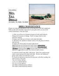
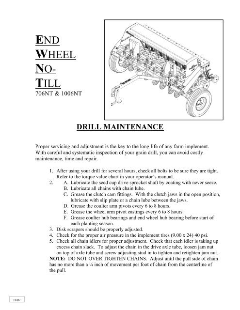
ENDWHEELNO-TILL<strong>706NT</strong> & <strong>1006NT</strong>DRILL MAINTENANCEProper servicing and adjustment is the key to the long life of any farm implement.With careful and systematic inspection of your grain drill, you can avoid costlymaintenance, time and repair.1. After using your drill for several hours, check all bolts to be sure they are tight.Refer to the torque value chart in your operator’s manual.2. A. Lubricate the seed cup drive sprocket shaft by coating with never seeze.B. Lubricate all chains with chain lube.C. Grease the clutch cam fittings. With the clutch jaws in the open position,lubricate with slip plate or a chain lube between the jaws.D. Grease the coulter arm pivots every 6 to 8 hours.E. Grease the wheel arm pivot castings every 6 to 8 hours.F. Grease coulter hub bearings and end wheel hub bearing before start ofeach planting season.3. Disk scrapers should be properly adjusted.4. Check for the proper air pressure in the implement tires (9.00 x 24) 40 psi.5. Check all chain idlers for proper adjustment. Check that each idler is taking upexcess chain slack. To adjust the chain in the drive axle tube, loosen jam nuton top of axle tube and screw adjusting stud in to tighten and retighten jam nut.NOTE: DO NOT OVER TIGHTEN CHAINS. Adjust until the pull side of chainhas no more than a ¼ inch of movement per foot of chain from the centerline ofthe pull.10-07
TRANSPORTINGWhen transporting the drill, transport locks should always be used. This will preventdamage to the drill and possible personal injury should hydraulic failure occur.Always disengage the lockout hub before transporting the drill.Lock-Out HubADJUSTMENT BEFORE GOING TO THE FIELDEngagedDisengagedLock Pin, Transport Position1.) After hooking the drill to the tractor and attaching hydraulic hoses, raise the drillup to maximum height and hold the hydraulic lever in the detent for 30 seconds, toallow the cylinders to rephase. This procedure will remove any air in the systemallowing the drill to raise and lower evenly. The rephasing procedure should berepeated several times a day to ensure that the drill continues to lift evenly.Remove the transport locks.2.) Lower the drill to the ground and pull ahead at field speed and inspect the coulterdepth. Once set, visually check to see if the drill box lid and tongue are parallel tothe ground, if not, raise or lower the draw bar clevis until the drill lid is level whendrilling.
3.) Check the seed cups for any foreign objects. Loosen wing nut on seed rate handleand open to 100% on the brass plate. Move handle back until the edge of the fluteis flush with the seam in the center of the cup (this is 50% open). A 7/8" block canalso be used to measure the 50% open measurement. If brass plate does not read50 on the seed rate handle, loosen the screws holding the brass plate and adjustplate to 50%. If an individual cup is not consistent, loosen the bolts holding thecup to the bottom of the seed box and adjust seed cup housing left or right asneeded.CupSeam = 50%4.) Each feed cup is equipped with a four-position adjustment handle.A. The highest position is for wheat and other small grains.B. The second is for soybeans and other large grains.C. The third is used if the seed is cracking in the second position.D. The bottom position is for clean out of the seed cup and will drain anygrain left in the seed box.DO NOT OPEN the seed cup handle to the bottom Seed-Rate position Handle with seed in the boxunless complete clean out is desired. Changing this handle will not change theseeding rate.NOTE: When storing the drill, it is best to place the handle in the bottom positionwith brass gauge reading “0” to help prevent rodent damage.
5.) Locate the desired seeding rate for the type of seed on the chart in the owner’smanual or on the lid of drill.A. Set the drive type for the seed and rate desired.B. Loosen wing nut on seed rate adjustment handle and move it past therequired number and then back to the correct number on the brass plate.C. Check seeding rate by running the calibration procedure outlined in owner’smanual or on the seed rate chart of drill lid.NOTE: The gear box has four drive types. Refer to the operator’s manual for thecorrect drive for a given seed. If the desired rate is not given, it is possible to refer tothe drive type rates and shift to a new drive type.MAIN SEEDBOX DRIVE TYPE RATIOSDrive Type 2 is 2.06 times faster than drive 1Drive Type 3 is 3.08 times faster than drive 1Drive Type 4 is 5.03 times faster than drive 1Drive Types6.) Heavy duty down pressure springs are standard equipment. The “W” clips areshipped from the factory in the bottom hole and should be left there in allapplications. The “W” clips can be raised one hole in the wheel tracks in extremeconditions. NOTE: If the “W Clips are raised too high, spring pressure increasesaccordingly. This will take away weight available to penetrate the coulters.7.) The depth of each opener is controlled by the height of the press wheel. Varyingthe height of the press wheel changes the seeding depth. Moving the “T” handle tothe front of the opener shallows the depth; moving the “T” handle towards the rearof the opener increases the depth. For a starting point place the “T” handle incenter.
8.) With the drill in the raised position, the clutch should be fully disengaged. The camplates will be on top of each other, and the jaws of the clutch will be fully separated.When the drill is lowered to planting position, the jaws of clutch should be fullyengaged. To adjust, loosen bolts on clutch tab, slide tab forward or rearward tochange and retighten bolts.FIELD ADJUSTMENTS1.) SET COULTER DEPTH: With the drill lowered, pull ahead at field speed untildesired coulter depth is achieved. Once satisfied, set the cylinder stop on the mastercylinder (the cylinder on the left side of drill). Re-check the coulter depth and adjustif needed. By doing this the coulter depth will always return to the same depth.A. If the cylinders are completely retracted and the coulters are not penetrating,add weight to the drill. DO NOT re-adjust the coulter shanks, as lowering thecoulter shanks will not increase coulter penetration.B. Coulter springs are preset at the factory giving the coulters an initial operatingforce of 400+ lbs. This setting is adequate for most field conditions. Resettingthe coulter spring shorter than 9¾ inches can cause premature failure ofHydraulic Depth Stop for Coultersparts.
2.) SPRING TENSION ON THE OPENERS: The “W” clips on the opener spring rodsshould be in the lowest hole. This is the correct location in all conditions. The “W”clips can be raised one hole in the wheel tracks only if penetration is not adequate.3.) SEED DEPTH: All opener “T” handles should be set the same (aboutmid range) when starting. Check seed depth by digging down to the seed, adjustto desired depth by moving the “T” handle. It may be desirable to put the T-handles in the rows behind the wheel tracks, one hole deeper to maintain proper seeddepth.OPTIONS1.) COIL TINE HARROW: A coil tine harrow is available as optional equipment thatwill pull residue over the seed and help in reducing soil crusting. Adjust the harrowfor no-till by raising the front bar to run 1 inch to 1½ inches higher than the rearbar. The front set of teeth should be set to run flatter than the rear bar.Press <strong>Wheel</strong> Depth <strong>Adjustment</strong>