You also want an ePaper? Increase the reach of your titles
YUMPU automatically turns print PDFs into web optimized ePapers that Google loves.
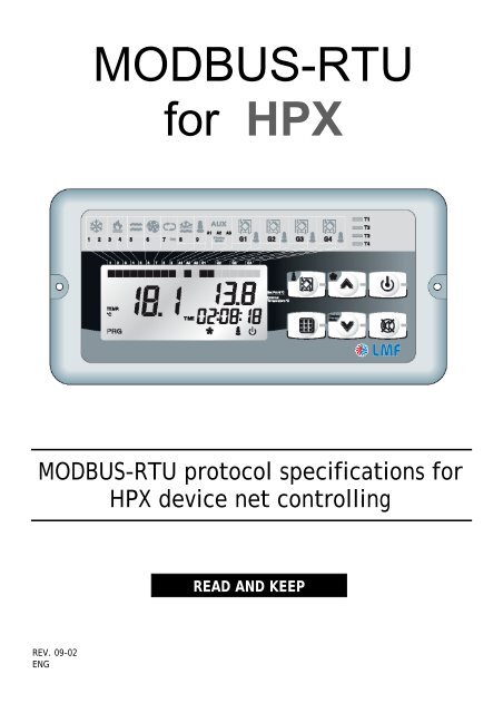
<strong>MODBUS</strong>-<strong>RTU</strong><strong>for</strong> <strong>HPX</strong><strong>MODBUS</strong>-<strong>RTU</strong> protocol specifications <strong>for</strong><strong>HPX</strong> device net controllingREAD AND KEEPREV. 09-02ENG
<strong>HPX</strong>INDEXGENERAL DESCRIPTIONPag. 2 1.1 Modbus protocolPag. 2 1.2 Serial configurationPag. 3 1.3 Message <strong>for</strong>mat (Frame)Pag. 4 1.4 Messagges synchronizationPag. 4 1.5 Error messagges (exceptions)COMMANDS DESCRIPTIONPag. 6 2.1 Register reading (0x03)Pag. 7 2.2 Single register writing (0x06)2REGISTERS AND ADDRESSES DESCRIPTIONPag. 8 3.1 Analog inputs (read-only)Pag. 8 3.2 Clock (read / write)Pag. 9 3.3 Parameters (read / write)Pag. 12 3.4 Inputs / outputs / alarms status (read-only)Pag. 14 3.5 Device status (read / write)GLOSSARYPag. 15 4 Glossary34
<strong>HPX</strong>1: DESCRIZIONE GENERALE1.1<strong>MODBUS</strong> PROTOCOLThe data communication system based on Modbus protocol allows to connect up to 247devices in a common RS485 line with standard <strong>for</strong>mat and communication mode.Communication takes place in half duplex by frame (transmitted continuously); onlymaster (PC , PLC ...) can start polling with slaves as question/answer (only one slaveaddressed) and the polled slave answers. The slave answers after a minimum pause of 3,5characters between received frame and the one to be transmitted.Also broadcast communication mode exists where the master send a request to all theslaves simultaneously, and they give no answer back; this mode it's not available with <strong>HPX</strong>controllers.The data serial transmission mode implemented on <strong>HPX</strong> controller is <strong>RTU</strong> type (RemoteTerminal Unit), where data are exchanged in binary <strong>for</strong>mat (8 bit characters).1.2SERIAL CONFIGURATIONSerial line:RS485Baud rate: 9600Data lenght:8 bitParity:noneStop bit: 1Serial transmission of characters in <strong>RTU</strong> <strong>for</strong>matStart bit 7 bit 6 bit 5 bit 4 bit 3 bit 2 bit 1 bit 0 StopRev. 02-09<strong>MODBUS</strong>-<strong>RTU</strong> SPECIFIC FOR <strong>HPX</strong>Pag. 3
<strong>HPX</strong>1.3MESSAGGE FORMAT (FRAME)Each message (Frame) is made, based on <strong>MODBUS</strong>-<strong>RTU</strong> standard, by the following parts:StartDeviceaddressFunctioncodeData CRC16 Stop4,5msec pause Byte Byte n x Byte LSByte MSByte 4,5msec pause- Start / Stop :Message starts with a 4,5ms pause (time higher than 3.5 times the charactertransmission period).See chap. 4.1 <strong>for</strong> further clarifications.- Device address:Device address with whom the master established the polling; it's a value between 1and 247. Address 0 is reserved to the broadcast, message sent to all slave devices (notactive on <strong>HPX</strong>). RS485 line allows to connect together up to 32 devices (1 Master + 31slaves), but with appropriate "bridges" or relay devices it is possible to use the wholelogical addressing field.- Function Code:Code of the function to be execute or already executed; On <strong>HPX</strong> device codes 0x03(register reading) and 0x06 (single register writing) are active.- Data:Data that must be exchanged.- CRC16:Error checking field based on CRC16 algorithm. CRC16 is calculated on the wholemessage by the master device which is trasmitting and attached to the message itself.The slave, at the end of reception, calculate CRC16 on the message and compare itwith the value added by the master; if the values does not match the message will beconsidered not valid and will be discarded without sending any answer to the master.The following fragment of C code shows the CRC16 calculation mode:unsigned int CRC16void Modbus_CRC(unsigned char *Frame, unsigned char FrameLength){unsigned char ByteCount;unsigned char i;unsigned char bit_lsb;CRC16 = 0xFFFF;<strong>for</strong> (ByteCount=0;ByteCount1;if (bit_lsb == 1)CRC16 ^= 0xA001;}}Pag. 4 <strong>MODBUS</strong>-<strong>RTU</strong> SPECIFIC FOR <strong>HPX</strong> Rev. 02-09
<strong>HPX</strong>}Rev. 02-09<strong>MODBUS</strong>-<strong>RTU</strong> SPECIFIC FOR <strong>HPX</strong>Pag. 5
<strong>HPX</strong>1.4MESSAGGES SYNCHRONIZATIONMessage synchronization between transmitter and receiver is made placing a pause onthe messages at least 4 ms. If the receiver does not receive any Byte <strong>for</strong> a 4 ms time,consider the last message completed and set the next Byte received ad the first one of anew message.The slave, once received the complete message, decode it and, if there are no errors,send the answer to the master. To send the answer, slave keeps RS485 line busy, wait a 4,5ms pause, send the complete message, wait a 4,5 ms pause and then release the RS485line.The master will have to consider these periods to avoid risks of trasmission overlap; inparticular must be set a proper answer reception time-out be<strong>for</strong>e starting a newtransmission (typical time-out value: 500msec or higher).1.5ERROR MESSAGGES (EXCEPTIONS)The <strong>HPX</strong> device, if not possible to complete the required operation, answer with an errormessage, in the following <strong>for</strong>mat:Device address Function Code Exception Code CRC16Byte Byte Byte LSByte MSByte- Device address:Address of slave device answering- Function Code:Function code Msb =1 (to show exception); i.e. 0x83 (reading) or 0x86 (writing)- Exception Code:Exception codes handled by <strong>HPX</strong> device are the following:Exceptioncode0x010x03DescriptionFunction notimplementedAddress notvalidException causeA function code not available was requested, different from0x03 and 0x06.It's generated in several situations:- a not implemented register was requested (or a notexistingarea)- a reading of more than 10 registers was requested- a reading of a number of registers more than theimplemented are was requested (starting from requestedaddress)- tried to write on a read-only area- tried to write an 8-bit parameter with a 16-bit value- CRC16:Error control field based on the CRC16 algorithm.Note:In case th <strong>HPX</strong> device identify in the received message an error on <strong>for</strong>mat or CRC16,message is discarded (considered not valid) and no answer is sent.Pag. 6 <strong>MODBUS</strong>-<strong>RTU</strong> SPECIFIC FOR <strong>HPX</strong> Rev. 02-09
<strong>HPX</strong>2: COMMANDS DESCRIPTIONAll the registers, to equalize the interpretation, are handled in a Word <strong>for</strong>mat (16 bit), evenif an 8-bit parameter is cointained.2.1REGISTER READING (0x03)Format of command sent by the Master:Register Number ofDevice address Function CodeaddressCRC16registersByte Byte MSByte LSByte MSByte LSByte LSByte MSByte- Device address:Address of slave device to be polled- Function Code:Function code to be executed, in this case register reading (0x03)- Register address:Starting register address <strong>for</strong> reading expressed with two Bytes; (MSByte) and (LSByte).- Number of registers:indicates the number of Word required from the starting address. If a number ofregisters more than 1 are requested, the answer message will provide all the registersrequired with consecutive addresses starting from the address shown on the "registeraddress" field.The number of registers to read is expressed on two Bytes, particularly <strong>for</strong> <strong>HPX</strong> controller(MSByte) must always be 0x00 and (LSByte) with range 1-10.- CRC16:Error control field based on the CRC16 algorithm.Format of answer message from slave:DeviceaddressFunctionCodeNo. Bytesof dataByte Byte ByteData 1 Data 2 Data n CRC16MSByteLSByteMSByteLSByteMSByteLSByteLSByteMSByte- Device address:Address of slave device answering- Function Code:Function code to be answered to, in this case register reading (0x03)- No. Bytes of data:contains the total Bytes number of data.Consider that the number of Bytes of data is double the number of registers (becausewe talk about word). I.e. if in the polling message 2 registers are requested, in theanswer message number of data Bytes must be setted as 4.- Data n :contains data sequences each expressed on two Bytes; (MSByte) and (LSByte).- CRC16:Rev. 02-09<strong>MODBUS</strong>-<strong>RTU</strong> SPECIFIC FOR <strong>HPX</strong>Pag. 7
<strong>HPX</strong>Error control field based on the CRC16 algorithm.Pag. 8 <strong>MODBUS</strong>-<strong>RTU</strong> SPECIFIC FOR <strong>HPX</strong> Rev. 02-09
<strong>HPX</strong>2.2SINGLE REGISTER WRITING (0x06)Format of command sent by the Master:RegisterDevice address Function CodeaddressDataCRC16Byte Byte MSByte LSByte MSByte LSByte LSByte MSByte- Device address:Address of slave device to be polled- Function Code:Function code to be executed, in this case single register writing (0x06)- Register address:address of register to write expressed with two Bytes; (MSByte) and (LSByte).- Data:Value to be assigned to the register expressed with two Bytes; (MSByte) and (LSByte).- CRC16:Error control field based on the CRC16 algorithm.Format of answer message from slave:Device address Function CodeRegisteraddressDataCRC16Byte Byte MSByte LSByte MSByte LSByte LSByte MSByteThe answer message is a simple echo of the polling message to confirm that the variablewas modified.WARNING :On the <strong>HPX</strong> device is not present a control on parameter's range ( apart the clock512-513 registers). Master must have all the controls to avoid setting of out-ofrangevalues. The range of parameters are shown on the tables in the nextchapters.Please do not send commands of writing on single register in a continuously way to avoidthat 100-Master controller keeps being busy on management of Modbus commandsreceived instead of communication with the console.Rev. 02-09<strong>MODBUS</strong>-<strong>RTU</strong> SPECIFIC FOR <strong>HPX</strong>Pag. 9
<strong>HPX</strong>3: REGISTERS AND ADDRESSES DESCRIPTIONEach register has a 16 bit dimension. It has been <strong>for</strong>med some blocks of variables (eachwith a different MSByte address) basing on the the type of these variables. In thefollowings paragraphs are described in the detail all the available blocks and, <strong>for</strong> eachblock, the implemented variables.3.1ANALOG INPUTS (READ-ONLY)Register Description Bytes range and meanings256257258ambienttemperature(resolution 0,5°C)externaltemperature(resolution 1°C)defrost probetemperature(resolution 1°C)MSByte whole part of temperature in °C with offset 45LSBytedecimal part of temperature in °C with offset 45range: 0..9MSByte whole part of temperature in °C with offset 45LSBytedecimal part of temperature in °C with offset 45range: 0..9MSByte whole part of temperature in °C with offset 45LSBytedecimal part of temperature in °C with offset 45range: 0..9259fans current MSByte 16-bit value high partabsorption (A)(resolution 0,1A) LSByte 16-bit value low partExamples <strong>for</strong> the temperature:(0x5A00) MSByte = 90, LSByte = 0 correspondent to a temperature of 90,0 – 45 = +45,0°C(0x4105) MSByte = 65, LSByte = 5 correspondent to a temperature of 65,5 – 45 = +20,5°C(0x2D00) MSByte = 45, LSByte = 0 correspondent to a temperature of 45,0 – 45 = 0,0°C(0x2B05) MSByte = 43, LSByte = 5 correspondent to a temperature of 43,5 – 45 = -1,5°C(0x0F05) MSByte = 15, LSByte = 5 correspondent to a temperature of 15,5 – 45 = -29,5°CExample <strong>for</strong> the current:(0x0030) MSByte = 0, LSByte = 48 correspondent to a current of 4,8 ANote: The visualization on display of the current is limited to 25.5A while register 259 reach32A3.2CLOCK (READ / WRITE)Pag. 10 <strong>MODBUS</strong>-<strong>RTU</strong> SPECIFIC FOR <strong>HPX</strong> Rev. 02-09
<strong>HPX</strong>3.3Register Description Bytes range and meanings512hour MSByte range: 0..59minutes LSByte range: 0..23513 day of the weekMSByterange: 1..7LSBytePARAMETERS (READ / WRITE)Rev. 02-09<strong>MODBUS</strong>-<strong>RTU</strong> SPECIFIC FOR <strong>HPX</strong>Pag. 11
<strong>HPX</strong>Register Description Bytes range and meanings768manualtemperaturesetpointMSByteLSBytein °C with offset 45range: 50..80, correspondent to +5..+35°C769r0temperaturedifferentialMSByteLSByterange: 1..4 °C770r1free-coolingdifferentialMSByteLSByterange: 1..4 °C771772773774tganti-freezeresistance insertiondifferentialt1first band P1temperaturesetpointt2second band P1temperaturesetpointt3P2 bandtemperaturesetpointMSByteLSByteMSByteLSByteMSByteLSByteMSByteLSByterange: 0..5 °Cin °C with offset 45range: 50..80, correspondent to +5..+35°Cin °C with offset 45range: 50..80, correspondent to +5..+35°Cin °C with offset 45range: 50..80, correspondent to +5..+35°C775tS1first band P1start hourMSByteLSBytestep of 10 minutesrange: 0..143, correspondent to 0:00..23:50776tF1first band P1end hourMSByteLSBytestep of 10 minutesrange: 0..143, correspondent to 0:00..23:50777tS2second band P1start hourMSByteLSBytestep of 10 minutesrange: 0..143, correspondent to 0:00..23:50778tF2second band P1end hourMSByteLSBytestep of 10 minutesrange: 0..143, correspondent to 0:00..23:50Pag. 12 <strong>MODBUS</strong>-<strong>RTU</strong> SPECIFIC FOR <strong>HPX</strong> Rev. 02-09
<strong>HPX</strong>Register Description Bytes range and meanings779tS3P2 bandstart hourMSByteLSBytestep of 10 minutesrange: 0..143, correspondent to 0:00..23:50780tF3P2 bandend hourMSByteLSBytestep of 10 minutesrange: 0..143, correspondent to 0:00..23:50781782783784785786787G1active program inAUTO mode onday 1G2active program inAUTO mode onday 1G3active program inAUTO mode onday 1G4active program inAUTO mode onday 1G5active program inAUTO mode onday 1G6active program inAUTO mode onday 1G7active program inAUTO mode onday 1MSByteLSByteMSByteLSByteMSByteLSByteMSByteLSByteMSByteLSByteMSByteLSByteMSByteLSByterange: 0..30 = P1, 1 = P2, 2 = P3, 3 = P4range: 0..30 = P1, 1 = P2, 2 = P3, 3 = P4range: 0..30 = P1, 1 = P2, 2 = P3, 3 = P4range: 0..30 = P1, 1 = P2, 2 = P3, 3 = P4range: 0..30 = P1, 1 = P2, 2 = P3, 3 = P4range: 0..30 = P1, 1 = P2, 2 = P3, 3 = P4range: 0..30 = P1, 1 = P2, 2 = P3, 3 = P4788d0defrost delayMSByteLSByterange: 1..30 minutes789d1defrost startsetpointMSByteLSBytein °C, with offset 45range: 25..50, correspondent to -20..+4°CNote: upper limit of d1 is (d2-1)Rev. 02-09<strong>MODBUS</strong>-<strong>RTU</strong> SPECIFIC FOR <strong>HPX</strong>Pag. 13
<strong>HPX</strong>Register Description Bytes range and meanings790d2defrost endsetpointMSByteLSBytein °C, with offset 45range: 25..50, correspondent to -19..+5°CNote: lower limit of d2 is (d1+1)791d3max. defrostdurationMSByteLSByterange: 1..254 minutes792F5fan stop duration793794795796F1min. time betweentwo start of eachcompressorF2min. time ofcompressorfunctioningducycle-inversionvalves activationdelayrCsecondcompressoractivation delayMSByteLSByteMSByteLSByteMSByteLSByteMSByteLSByteMSByteLSByterange: 1..254 secondsrange: 1..15 minutesrange: 1..15 minutesrange: 10..20 secondsstep of 5 secondsrange: 1..120, correspondent to 5..600 secondiPag. 14 <strong>MODBUS</strong>-<strong>RTU</strong> SPECIFIC FOR <strong>HPX</strong> Rev. 02-09
<strong>HPX</strong>3.4INPUTS / OUTPUTS / ALARMS STATUS (READ-ONLY)Register Description Bytes meanings1280 outputs statusMSByteLSBytebit 7(MSb)bit 6bit 5bit 4 Not usedbit 3bit 2bit 1bit 0 (LSb)bit 7by-pass shutter relay (K9)(MSb)bit 6 cycle-inversion valve 2 relay (K8)bit 5 compressor 2 relay (K7)bit 4 cycle-inversion valve 1 relay (K5)bit 3 anti-freeze resistance relay (K4)bit 2 fans relay (K3)bit 1 aux. heater resistances relay (K2)bit 0 (LSb) compressor 1 relay (K1)Register Description Bytes meanings1281 inputs statusMSByteLSBytebit 7(MSb)bit 6bit 5bit 4 Not usedbit 3bit 2bit 1bit 0 (LSb)bit 7not used(MSb)bit 6 remote OFF inputbit 5 (EP) maintenance alarmbit 4 (E1) compressor 2 protectionbit 3 (EF) missing ventilation alarmbit 2 (E8) supply dirty filters alarmbit 1 (E7) exhaust dirty filters alarmbit 0 (LSb) (EC) compressor 1 protectionRev. 02-09<strong>MODBUS</strong>-<strong>RTU</strong> SPECIFIC FOR <strong>HPX</strong>Pag. 15
<strong>HPX</strong>Register Description Bytes meanings1282 alarms statusMSByteLSBytebit 7(MSb)bit 6bit 5bit 4 Not usedbit 3bit 2bit 1bit 0 (LSb)bit 7not used(MSb)bit 6 master - console disconnection errorbit 5 not usedbit 4 (E9) too cold external air alarmbit 3 (E2) EEPROM errorbit 2 (E6) defrost probe anomalybit 1 (E5) external probe anomalybit 0 (LSb) (E0) ambient probe anomalyPag. 16 <strong>MODBUS</strong>-<strong>RTU</strong> SPECIFIC FOR <strong>HPX</strong> Rev. 02-09
<strong>HPX</strong>3.5DEVICE STATUS (READ / WRITE)Register Description Bytes meanings1536 device statusMSByteLSBytebit 7 not used(MSb)bit 6 not usedbit 5 not usedbit 4 not usedbit 3 not usedbit 2 not usedbit 1enable chrono-thermostat statusmodificationbit 0 (LSb) enable stand-by status modificationbit 7 not used(MSb)bit 6 not usedbit 5 not usedbit 4 not usedbit 3 not usedbit 2 not usedchrono-thermostat statusbit 11=AUTO ( chrono-thermostatenabled)0=MAN ( chrono-thermostat disabled)stand-by statusbit 0 (LSb) 1 = stand-by0 = ONTo request modification of one of the device status bit, the master must send on LSByte therequired value <strong>for</strong> the bit and on MSByte the correspondent bit setted to 1.Example: to <strong>for</strong>ce stand-by status, master must send MSByte = 0b00000001 and LSByte =0b00000001. To disable chrono-thermostat must send MSByte = 0b00000010 e LSByte =0b00000000.Rev. 02-09<strong>MODBUS</strong>-<strong>RTU</strong> SPECIFIC FOR <strong>HPX</strong>Pag. 17


