SmartSensor HD - Interprovincial Traffic Services
SmartSensor HD - Interprovincial Traffic Services
SmartSensor HD - Interprovincial Traffic Services

Create successful ePaper yourself
Turn your PDF publications into a flip-book with our unique Google optimized e-Paper software.
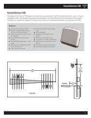
6 INTRODUCTION • SMARTSENSOR <strong>HD</strong> USER GUIDE˽˽Sensor cableAdditional products may be purchased through your distributor. The following optionalitems are not included unless specifically ordered (check packing list for actual inventory):˽˽Contact closure adapter such as the Click! 100, 104, 110, 112/114, or 172/174.˽˽Click 200 surge protector˽˽Click 201/202 AC to DC converter˽˽Click 210 circuit breaker˽˽Click 230 AC surge protector˽˽<strong>SmartSensor</strong> <strong>HD</strong> User Guide (doesn’t have to be purchased, but does have to be requestedfrom Wavetronix)Selecting a Mounting LocationConsider the following guidelines when selecting a mounting location:˽˽˽˽˽˽˽˽˽˽˽˽Lane Coverage – Sensor mounting locations should be selected so that all monitoredlanes are within 6 to 250 ft. (1.8 to 76.2 m) of the sensor and run parallel with eachother. Multiple sensors should be considered if more than 10 lanes need to be simultaneouslymonitored. If lanes do not need to be simultaneously monitored, up to 22 lanescan be configured for collection by a single sensor.Parallel Lanes – When the sensor is used to collect both mainline and ramp data, thepole position should be selected so that the on and off ramp lanes run parallel withthe mainline. If lanes are not parallel, installation of multiple <strong>SmartSensor</strong> <strong>HD</strong> unitsshould be considered to achieve the sensor’s ±2 degree side-to-side angle requirement.Sensors on the Same Pole – When multiple sensors are mounted on the same pole,they will not be subject to interference if they are configured to operate using differentRF channels and are separated vertically by a few feet. The higher sensor would typicallybe used for the lanes farther from the pole in order to minimize occlusion.Sensors on Opposing Poles – <strong>SmartSensor</strong> <strong>HD</strong> units facing each other on opposingpoles should operate on different RF channels and be separated by a 70-ft. (21.3-m)lateral offset, if possible.Line of Sight – The <strong>SmartSensor</strong> <strong>HD</strong> is designed to work accurately in the presenceof barriers, but in general if there is an alternate mounting location that would avoidany type of structural occlusion, this is preferred. Avoid occlusion by trees, signs, andother roadside structures.Neighboring Structures and Parallel Walls – For best performance, it is preferred thatsensor locations have a 30-ft. (9.1-m) lateral separation from overhead signs, overpasses,tunnels, parallel walls, and parallel-parked vehicles in order to avoid multiplereflection paths from a single vehicle.