revos Industrial Multipole Connector Catalog - Wieland Electric
revos Industrial Multipole Connector Catalog - Wieland Electric
revos Industrial Multipole Connector Catalog - Wieland Electric

You also want an ePaper? Increase the reach of your titles
YUMPU automatically turns print PDFs into web optimized ePapers that Google loves.
evos <strong>Industrial</strong> <strong>Multipole</strong> <strong>Connector</strong>s<strong>revos</strong><strong>Industrial</strong> <strong>Multipole</strong> <strong>Connector</strong>s<strong>Catalog</strong> 2013
Sales andMarketing Centerin Bamberg Company headquartersin Bamberg STOCKO main plant inWuppertalautomationbuildingelectronicsACTIVE WORLDWIDE.The <strong>Wieland</strong> Group employs more than2,000 people all around the globe. Withsome 15 locations and subsidiaries, and salespartners in more than 70 countries, the<strong>Wieland</strong> Holding is present in nearly allimportant key markets worldwide.Always with a clear commitment to theGerman location where most of the productsare still manufactured.The group makes us strongThe <strong>Wieland</strong> Holding is based inBamberg, Bavaria, and comprises twoindependently acting subsidiaries:<strong>Wieland</strong> <strong>Electric</strong> and STOCKO Contact.Groundbreaking innovations made<strong>Wieland</strong> <strong>Electric</strong> one of the leadingsuppliers of electrical connectiontechnology. This company, foundedin Bamberg in 1910, is the largestsubsidiary of the <strong>Wieland</strong> Holding.STOCKO Contact is based in Wuppertaland joined the <strong>Wieland</strong> Group in 2001.Stocko has also more than 100 yearsof company history to its credit and isone of the greatest manufacturers ofconnector systems and crimp contacts.2
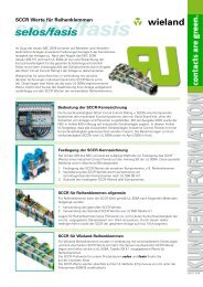
contacts are greenEstablished in industriesControl cabinet engineering, industrialautomation, building system technology– our large product portfolio providessolutions for all kinds of applications.From innovative interface and networktechnology to terminal blocks to„safety first“ – with modular systemsolutions and safety components.With <strong>Wieland</strong> products in your controlcabinet, you are always on the safe side.Energy bus systems for distributedautomation or indoor and outdoor fieldbus components – <strong>Wieland</strong> technologycan be found everywhere, and in allkinds of applications.In building system technology, <strong>Wieland</strong><strong>Electric</strong> is the world market leader inpluggable eletrical installation.There are good reasons why oursystem solutions can be foundin the most spectacular buildingprojects worldwide. When it comes toelectronic networking, <strong>Wieland</strong> leadsthe way to the “intelligent house”.Welcome Future<strong>Wieland</strong> <strong>Electric</strong> is 100 years young,and full of innovative energy. Andour commitment for the future is notonly to find constantly new systemsolutions for our customers but alsosocial responsibility.Environmentally friendly high-techproducts, manufactured to the latestproduction standards, an auditedenvironmental management systemand substantial investments in ourlocations are all part to this concept.Global commitment and sustainableregional action – <strong>Wieland</strong> <strong>Electric</strong> is fitfor the future: Contacts are green.3
contacts are green8 An overview of heavy duty connectors10 General design of a <strong>revos</strong> industrial multipole connectors12 The locking mechanism of the industrial multipole connectors14 Connection technologies16 Housing series20 Contact inserts - Overview24 Product matrix26 Contact inserts28 <strong>revos</strong> mini32 <strong>revos</strong> basic58 <strong>revos</strong> dd60 <strong>revos</strong> hd68 <strong>revos</strong> power80–91 <strong>Connector</strong> and <strong>Multipole</strong> adapter with trigger action frame96 <strong>revos</strong> it98 <strong>revos</strong> 100 <strong>revos</strong> flex116 Housings118 <strong>revos</strong> mini120 <strong>revos</strong> basic224 <strong>revos</strong> hd238 <strong>revos</strong> 258 <strong>Multipole</strong> connector sets with 4 components Screw connection260 Accessories262 Mounting frames264 Cover- and Reducer plate266 Coding accessories270 Cable glands274 Protective covers278 Tools279 Marking tag carriers282 facts&DATA284 Conductor connections, Current load capacity, tightening torque288 Explanations of applications in hazardous areas290 Installation spacing and mounting dimensions294 Crimping tool and Assignment of contacts to appropriate crimping tool296 Selection criteria and characteristics of the different contact surfaces298 Definition of the IP degrees of protection301 Derating behavior of <strong>revos</strong> industrial multipole connectors302 Detailed table of contents304 Spanning various industries and products.306 Service | Support307 <strong>Wieland</strong> subsidiaries5
6<strong>revos</strong>
evosThe <strong>revos</strong> programAn overview of heavy duty connectorsHeavy duty connectors are specifically designed foruse in especially tough environment conditions.The main areas of use are the automotive industry,in packaging machinery and equipment, as well as forinstrumentation, control and automation equipment.They permit simple and time-saving installation ofmachinery and equipment. Their housings protectagainst mechanical impact and prevent entry of spraywater and dust. The system‘s sub-assemblies canundergo a quality check in house, which simplifies installationand commissioning at their end use location.7
evosHousing families:<strong>revos</strong> miniThe design of the housings for the connectors of <strong>revos</strong> mini is verycompact and available in two materials:• Die cast zinc alloy• PolyamideYou will find <strong>revos</strong> mini-housings on pages 118–119.<strong>revos</strong> basicPGthreadsare availableon request!The housing of the BASIC series are available in size 6 to 48. Forconvenient connection of the cables this series is also available withenlarged cable entry in increased height design in sizes 6H–24H.The housings are made of die cast aluminum with, silicon-free finish.You will find <strong>revos</strong> basic-housings on pages 120–223.<strong>revos</strong> hdPGthreadsare availableon request!The housings of the HD series are available in size 10/15 to 32/50.You will find <strong>revos</strong> hd-housings on pages 224–237.Special multipole connector designs:<strong>revos</strong> <strong>revos</strong> multipole connectors are designed for special applicationsin hazardous areas. Their use in zone 1 for intrinsic circuits hasbeen approved by the BVS test institute. The housings for the multipoleconnectors are manufactured from die cast zinc alloy.You will find <strong>revos</strong> -contact inserts on pages 98–99.You will find <strong>revos</strong> -housings on pages 238–257.Operating instructions for plug connectors, see facts&DATA.<strong>revos</strong> itData cable feed-throughs – the ideal solution for the installation ofpre-assembled cables to enclosures. Sealed and with strain relief.Inserts with D-Sub connectors 9 to 100 pole.You will find <strong>revos</strong> it products on pages 96–97.<strong>revos</strong> mot<strong>revos</strong> mot plug connectors with plastic housings, simple and easyhandling due to its unique latching system.You will find <strong>revos</strong> mot products on pages 114–115.Subject to change without further notice9
evosGeneral design of a <strong>revos</strong>industrial multipole connectors1234567810Subject to change without further notice
evos1. Cable glandsF o r <strong>revos</strong> industrial connectors the following cable glands are available:• Cable gland without strain relief, protection degree IP54, 7x.xxx.xxxx.0 fully assembled• Cable glands, protection degree IP68, available as accessories in plastic or brass• EMC cable glands2. HoodsAluminum die cast alloy, silicon-free finish (housings for <strong>revos</strong> - and <strong>revos</strong> mini are manufactured fromdie cast zinc alloy)• Low and increased height designs available• Cable entry at the side, on top or at the front• With or without locking levers3. Female insertsAvailable in the following connection techniques:• Screw connection• Spring clamp connection• Crimp connection4. Coding accessoriesCoding pins, female coding pieces and coding bolts5. Coding boltsCoding pieces are used for coding 690 V contact inserts. In the 690 V housings the coding ribs are removedand insulating tape is attached inside the housing in order ensure the creepage distances and clearancesto live parts. This mechanical coding prevents the 690 V contact inserts from being mounted in500 V housings.6. Male insertsAvailable in the following connection techniques:• Screw connection• Spring clamp connection• Crimp connection7. Locking leversSingle or double locking lever in plastic, steel or stainless steel design.8. BasesAluminum die cast alloy, silicon-free finish (housings for (<strong>revos</strong> - und <strong>revos</strong> mini are manufacturedfrom die cast zinc alloy)• Low and increased height designs available• Open-bottom and closed-bottom bases• Single or double locking lever of plastic, steel or stainless steel• Coupling for “cable-to-cable connections”Subject to change without further notice11
evosThe locking mechanism of the<strong>revos</strong> basic industrial multipole connectorsThe locking levers secure the mechanical connectionbetween hood and housing. The locking mechanism isalso a main determinant of the connector’s IP protectionrating. <strong>Wieland</strong>’s standard <strong>revos</strong> basic connectorsin size 6 to 24 are equipped with locking levers that aremade of two components.The handle consists of flame-retardant and halogenfreeplastic material and ensures convenient and almostwear-free locking. The retention force is provided by aspring component that is made of V2A stainless steeland also resists aggressive environmental conditions.Locking features:• Low-wear locking mechanism• High holding forces• Plastic material suitable for outdoor applications• Salt and seawater resistant, UV resistant• During overhead mounting the lever will remainin the open position• Replaceable• Self-extinguishing plastic material accordingto UL 94 V0Single locking lever(long-side lever)Spring componentmade of V2A steelDouble locking lever(narrow-side lever)Handlemade of flameretardantplastic accordingto UL94 V012 Subject to change without further notice
evosIn general we distinguish levers on the hood and leverson the base, as well as single locking levers (on the longside) and double locking levers (on the narrow side).On the opposite hood or base there are studs to whichthe lever latches.The following lock types are available:One long-side lever(single locking lever)Two narrow-side levers(double locking lever)<strong>Connector</strong>s for cable-to-cable couplings:One long-side lever(single locking lever)Two narrow-side levers(double locking lever)Locking levers made of steel or stainless steel are available on request.In case of any questions our connector hotline (+49 951/9324-997) will be happy to assist you.Subject to change without further notice13
evosConnection technologiesScrew connection technology:This connection technology is the one most frequently used today. Screw connectors aredesigned according to EN 60 999/VDE 0609.Features of this connection technology:• Operation is simple and easy• No special tools required• High-quality connection that can be used for all areas of application• Non-permanent connection, rewiring possibleThe contact point can be delivered with or without wire protection.Clamping bodies with wire protection do not require any preparation of the wires.Clamping bodies without wire protection require appropriate preparation of the wires in casefine-stranded wires are used.Spring clamp connection technology:In the last few years this connection technology has been established as an industrialstandard. Spring clamp connectors are designed according to EN 60 999/VDE 0609.Features of this connection technology:• Easy handling• No special tools required• High-quality connection even under vibration• Non-permanent connection, rewiring possibleFor contact inserts with spring clamp connection technology all wire types (solid, stranded,fine-stranded) can be used without special preparation of the wires.When ferrules are used they must be crimped to the wire by means of a special positivelydriven crimping tool.Crimp connection technology:This connection technology provides the highest quality, but is also the most demanding. Thetechnical requirements for crimp connections are defined in the IEC 60 352-2 standard. Crimpconnections must always be produced using a crimping tool that has been designed for thecontact. <strong>Wieland</strong> crimping tools are specifically adapted to the contacts and thus ensure apermanent and corrosion-resistant connection.Features of this connection technology:• High-quality connection similar to cold welding• Consistant repeatability of the crimp connection• Suitable for automation during pre-assembly of cable harnesses• Compact design that allows a high contact density• Special crimping tool required• Permanent connection14 Subject to change without further notice
evosScrew connection technology:Screw terminals are measured in accordance with EN 60 999/VDE 0609.Please refer to the respective tightening torques from table 4 on page 287.Spring clamp connection technology:Operating instructions:1. Insert the screwdriver using a slight curvingmotion into the rectangular opening.2. Open the clamping body.The screwdriver will stay in position, andhold the clamping body open.3. Insert the wire into the round wire entry guideand remove the screwdriver.Screwdriver: 0.6 mm x 3.5 mmPart number: 06.502.4000.0Crimp connection technology:Using the suitable tools when producing crimp connectionsis essential. Correct and gas-tight connections canonly be ensured by tools that are particularly adapted tothe contact.<strong>Wieland</strong> crimping tools compress the contact point witha so-called B crimp or a square crimp to make it gas-tight.A contact to tool assignment can be found on page 295.Micrographof a B crimpMicrographof a square crimpContact materials:<strong>revos</strong>-connectors are available with tin-plated, silver-plated or gold-plated contacts.The basic material is a high-quality copper alloy.For exact explanations, see pages 296–297.Subject to change without further notice15
evosHousing series <strong>revos</strong> hdSingle locking leverHoodsBasesSize (GB):• GB 10/15, 16/25Double locking leverHoodsBasesSize (GB):• GB 32/50Coupling housingsAll bases are also available with a protective cover.For an assignment of the contact inserts to the housing sizes see page 20-23 as well as the product matrixon page 24-25.Subject to change without further notice17
evosHousing series <strong>revos</strong> mini and <strong>revos</strong> <strong>revos</strong> miniHoodsBasesCoupling housingsCover withoutgasket for femaleinsertsCover withgasket for maleinserts<strong>revos</strong> HoodsBasesSize (GB):• GB 10Ex, 16Ex, 24Ex, double locking lever• GB 6Ex, 48Ex, single locking leverCoupling housingsBases are also available with a protective cover!18 Subject to change without further notice
evosSubject to change without further notice19
evosContact insertsContact inserts for the housings of the <strong>revos</strong> basic seriesSize BASIC 500 V / 16 A BASIC 400/690 V / 16 A BASIC 690 V / 16 A BASIC 830 V / 16 A EE 500 V / 16 A6/6H6 + ground4/2 Switchingcontacts + ground10 + ground10/10H10 + ground 3/2 Switching contacts + ground8/2 Switchingcontacts + ground3/2 Switchingcontacts + ground18 + ground16/16H16 + ground 6/2 Switching contacts + ground14/2 Switchingcontacts + ground6/2 Switchingcontacts + ground32 + ground24/24H24 + ground10/2 Switchingcontacts + ground22/2 Switchingcontacts + ground10/2 Switchingcontacts + ground46 + ground3232 + ground20/4 Switchingcontacts + ground28/4 Switchingcontacts + ground4848 + ground26/4 Switchingcontacts + ground32/4 Switchingcontacts + ground44/4 Switchingcontacts + ground20/4 Switchingcontacts + ground20 Subject to change without further notice
evosDD 250 V / 10 A HD 250 V / 10 A POWER 230–690 V / 16–100 A FLEX 100 – 1000 V / 4 – 82 A Size24 + ground 2 Modules6/6H42 + ground 3 Modules10/10H72 + ground 40 + ground6/6 +ground4/6 +ground6 +ground4/2 +ground4 +ground5 Modules16/16H24/24H108 + ground 64 + ground 3/3/6 + ground 7 Modules3280 + ground48Subject to change without further notice21
evosContact insertsContact inserts für <strong>revos</strong> hd-housingsSize HD 10/16 250 V / 16 A HD 15/25 250 V / 10 A10/1510 + ground 15 + ground16/2516 + ground 25 + ground32/5032 + ground 50 + groundContact inserts for <strong>revos</strong> mini-housingsSize 250 – 400 V / 10 A 400 V / 10 A 400 V / 16 A 50 – 250 V / 10 A 50 V / 10 A 690 V / 10 A33 + ground 4 + ground 5 + ground 7 + ground 8 12Contact inserts for <strong>revos</strong> -housingsSize 6Ex 10Ex 16Ex 24Ex 48Ex90 V16 A6 + PE 10 + PE 16 + PE 24 + PE 48 + PE22Subject to change without further notice
evosContact inserts<strong>revos</strong> flex-modular insertsModules for power supply2-pole1000 V/82 AScrew3-pole630 V/40 ACrimp5-pole250 V/20 ACrimp4-pole1000 V/16 ACrimp4-pole400 V/14 AFederkraftModules for signal distribution High voltage Compressed air10-pole250 V/10 ACrimp/LWL-POF20-pole100 V/4 ACrimp2-pole5.5 kV/20 ACrimpPneumatic1-pole10 bar – Ø 2.5/4 mmPneumatic2-pole10 bar – Ø 2.5/4 mmBus systemsSpecial modulesUSB4-pole30 V/1 AScrewProfibus4-pole30 V/1 AScrewEthernet8 plus 4-pole30 V/1 A / 400 V/10 ACrimp/optical fiberModular blind piece<strong>revos</strong> mot special designs690 V / 16 A10 + groundSubject to change without further notice23
evosProduct matrixThe <strong>revos</strong> product matrix provides an overview ofthe available families of contact inserts and theirmatching housing series. Horizontally you can findthe contact inserts sorted per family and with indicationsfor rated voltage, rated current and connectiontechnology. Vertically the housing series andtheir variations in size are shown. Matching combinationsare found in the matrix.The restrictions of the <strong>revos</strong> flex and <strong>revos</strong> hdcontact inserts are caused by their depth and cabledensity inside the housing when fully equippedwith contact inserts. In case of any questions regardingthese combinations, our connector hotline(+49 951 9324-991) will be happy to assist you.Housing series Material Variantion Size (GB) Locking levers Hoods page Bases pageBASIC Aluminum die cast 500 V 6 Single 120 12410 Single 132 136Double 140 14616 Single 160 164Double 168–170 17424 Single 188 192Double 196–198 202500 V/690 V 32 Double 216 217500 V/690 V 48 Single 218 220690 V 6 Single 128 13010 Single 150 152Double 154–156 15816 Single 178 180Double 182 18624 Single 206 208Double 210–212 214500 V 6H Single 122 126Increased height 10H Single 134 138designDouble 144 14816H Single 162 166Double 172 17624H Single 190 194Double 200–201 204690 V – large 16XL Double 183wiring space 24XL Double 211EMC housings 6/6H Single 222 22310/10H Double 222 22316/16H Double 222 22324/24H Double 222 223HD Aluminum die cast 250 V 10/15 Single 224 22616/25 Single 228 23032/50 Double 232,234 236MINI Polyamide Plastic 3 Single 118 119Die cast zinc alloy Metal 3 Single 118 119Die cast zinc alloy 90 V 6 Single 238 24010 Double 242 24416 Double 246 24824 Double 250 25248 Single 254 256MOT Polyamide 690 V 10 + ground Push-Pull 114 114H = Increased height design; XL = Large wiring space24Subject to change without further notice
evosContact insertsWiring techniqueS = screw F = spring clamp C = srimp L = optical fiberBASIC BASIC EE BASIC BASIC BASIC HD 40/64 POWER FLEX DD HD 10/16//32 HD 15/25 MINI MOT500 V 500 V 400V/690V 690 V 830 V 250 V 230–690 V 100–1000 V 250 V 250 V 250 V 50 – 400 V 90 V 690 V16 A 16 A 16 A 16 A 16 A 10 A 16 –100 A 4–82 A 16 A 16 A 10 A 10 A 16 A 16 ASFF C S S F C S C S S C S S CCL32–39 40–41 50–51 52–55 56–57 64–65 68–74 100–113 58–59 60–61 62–63 28–31 98–99 115• • ° °• • ° °• • ° °• • ° ° °• • ° ° °• • ° ° •• • ° ° •• • • • • •• • • • • • • •• • • • • °• • • • • °• • • • • °• • • • • • °• • • • • • °• • • • • • °• • • • • • °• • • •• • • •• • • •• • • • • •• • • • • •• • • • • •• • • • • •• • • • • • • • •• • • • • • • • •• • • •• • • •• • • • • •• • • • • •• •• •• ••••••••°= usable subject to restrictions• = usable without any restrictionsSubject to change without further notice25
evos<strong>revos</strong> contact insertsoffer many possibilitiesThe task of the contact inserts is distribution ofpower and signals. The contact inserts are availablein 2- to 216-pin design. They are suitable for currentfrom 4 to 100 A and voltages up to 5.5 kV.<strong>revos</strong> mini - Their especially compact design allowsthem to fit in applications for machine, control andswitching systems, or also in small motors and lightingequipment, and also serve as classic contact insertsfor industrial heavy duty connectors.The contact inserts are available in 6 to 92-pin design.<strong>revos</strong> basic is able to meet the toughest demands andso is used, for example, in the automotive industry, themachinery and equipment industry, in conveyor systemsand in measurement and control technology.27
evos miniContact insertsContact inserts <strong>revos</strong> miniM D3-pole + ground4-pole + groundDescription Type Part No. P.U.Contact inserts <strong>revos</strong> mini3-pole + groundMale insert MIN STS 3 2.5 40 73.310.0353.0 10Female insert MIN BUS 3 2.5 40 73.300.0353.0 10Contact inserts <strong>revos</strong> mini4-pole + groundMale insert MIN STS 4 2.5 40 AG 73.310.0453.0 10Female insert MIN BUS 4 2.5 40 AG 73.300.0453.0 10Technical data 3-pole + ground 4-pole + groundRated voltageInstalled in a plastic housing400 VInstalled in a metal housing L-PE 250 V / L-L 400 V 400 VRated voltage according to UL/CSA 600 VRated impulse voltagePlastic housing4 kVMetal housing4 kVRated current10 ADegree of pollution 3Rated cross sectionEN 60999 0.5 – 2.5 mm 2UL 18 – 16 AWG 22 – 12 AWGCSA22 – 12 AWGContactsMaterialCopper alloySurface Sn AgInsulation strip length4 mmContact resistance ≤ 2 mΩ ≤ 1.5 mΩMating cycles 50 200Screwshead design / recomm. torqueMounting screwsM3 / 0.5 – 0.7 NmClamping screwsM3 / 0.5 – 0.7 NmGround conductor screwsM3 / 0.5 – 0.7 NmTemperature range -40 – +120 °CHousing <strong>revos</strong> mini Page 118–119Dimensions3-pole + ground4-pole + ground7-pole + ground8-pole28 Subject to change without further notice
evos miniContact insertsContact inserts <strong>revos</strong> miniM D7-pole + ground8-poleDescription Type Part No. P.U.Contact inserts <strong>revos</strong> mini7-pole + groundMale insert without crimp contacts MIN STC 7 25 73.710.0753.0 10Female insert without crimp contacts MIN BUC 7 25 73.700.0753.0 10Contact inserts <strong>revos</strong> mini8-poleMale insert without crimp contacts MIN STC 8 05 73.710.0853.0 10Female insert without crimp contacts MIN BUC 8 05 73.700.0853.0 10Contacts for crimp version mm 2 / AWGMale reel contacts, Sn 0.2 – 0.56 / 24-20 05.544.0900.0 5000Female reel contacts, Sn 0.2 – 0.56 / 24-20 02.124.0900.0 5000Male reel contacts, Sn 0.75 – 1.5 / 18-16 05.544.1000.0 5000Female reel contacts, Sn 0.75 – 1.5 / 18-16 02.124.1000.0 5000Male single contacts, Sn 0.2 – 0.56 / 24-20 05.544.0929.0 200Female single contacts, Sn 0.2 – 0.56 / 24-20 02.124.0929.0 200Male single contacts, Sn 0.75 – 1.5 / 18-16 05.544.1029.0 200Female single contacts, Sn 0.75 – 1.5 / 18-16 02.124.1029.0 200Male reel contacts, Au 0.5 – 1.5 / 20-16 05.544.1400.0 5000Female reel contacts, Au 0.5 – 1.5 / 20-16 02.124.1400.0 5000Male single contacts, Au 0.5 – 1.5 / 20-16 05.544.1429.0 200Female single contacts, Au 0.5 – 1.5 / 20-16 02.124.1429.0 200Technical data 7-pole + ground 8-poleRated voltageInstalled in a plastic housing 250 V 50 VInstalled in a metal housing 50 V 50 VRated voltage according to UL/CSA 600 V 42 VRated impulse voltagePlastic housing 4 kV 0.8 kVMetal housing0.8 kVRated current10 ADegree of pollution 3Rated cross sectionEN 60999 0.2 – 1.5 mm 2UL18 – 16 AWGCSA24 – 16 AWGContactsMaterialCopper alloySurfaceAu or SNInsulation strip length4 mmContact resistance4 mΩMating cycles Sn 50 / Au 500Screwshead design / recomm. torqueMounting screwsM3 / 0.5 – 0.7 NmClamping screws -Ground conductor screws -Temperature range -40 – +120 °CDescription Type Part No. P.U.AccessoriesCrimping tool 95.101.0800.0 1Crimping die “E“ 05.502.2400.0 1Contact positioner “2“ 05.502.3200.0 1Extraction tool 05.502.0000.0 1Housing <strong>revos</strong> mini Page 118–119Derating curveaccording to IEC 60512 sec. 3<strong>revos</strong> mini10 A / 2.5 mm 2 / 1.5 mm 23-pole4-pole7-poleCurrent [A]Upper temperature limit8-poleAmbient temperature [°C]Subject to change without further notice29
evos miniContact insertsContact inserts <strong>revos</strong> miniM D pending5-pole + groundDescription Type Part No. P.U.Contact inserts <strong>revos</strong> mini5-pole + groundMale insert without crimp contacts MIN STC 5 25 AG 73.710.0553.0 10Female insert without crimp contacts MIN BUC 5 25 AG 73.700.0553.0 10Contacts for crimp version mm 2 / AWG, turned ø 2.5 mmMale insert 0.5 / 20 05.543.70xx.0 200Female insert 0.5 / 20 02.123.70xx.0 200Male insert 0.75 – 1 / 18 05.543.71xx.0 200Female insert 0.75 – 1 / 18 02.123.71xx.0 200Male insert 1.5 / 16 05.543.72xx.0 200Female insert 1.5 / 16 02.123.72xx.0 200Male insert 2.5 / 14 05.543.73xx.0 200Female insert 2.5 / 14 02.123.73xx.0 200Male insert 4 / 12 05.543.75xx.0 200Female insert 4 / 12 02.123.74xx.0 200Surface silver-plated xx = 02 / gold-plated xx = 01Technical dataRated voltageInstalled in a plastic housingL-PE 250 V / L-L 400 VInstalled in a metal housingL-PE 250 V / L-L 400 VRated voltage according to UL/CSA 600 VRated impulse voltagePlastic housing4 kVMetal housing4 kVRated current16 ADegree of pollution 3Rated cross sectionEN 60999 0.5 – 4 mm 2 , ground: 2.5 mm 2UL20 – 12 AWGCSA20 – 12 AWGContactsMaterialCopper alloySurfaceAu or AgMating cycles 200Screws head design / recomm. torqueMounting screwsM3 / 0.5 – 0.7 NmClamping screws -Ground conductor screwsM3 / 0.5 – 0.7 NmTemperature range -40 – +120 °CDescription Type Part No. P.U.AccessoriesCrimping tool 95.101.0800.0 1Crimping die “B“ 05.502.2100.0 1Contact positioner “3“ 05.502.3300.0 1Extraction tool 05.502.3500.0 1Housing <strong>revos</strong> mini Page 118–119Dimensions5-pole + ground12-pole + ground30 Subject to change without further notice
evos miniContact insertsContact inserts <strong>revos</strong> miniM D pending12-pole + groundDescription Type Part No. P.U.Contact inserts <strong>revos</strong> mini12-pole + groundMale insert without crimp contacts MIN STC 12 40 AG 73.710.1253.0 10Female insert without crimp contacts MIN BUC 12 40 AG 73.700.1253.0 10Contacts for crimp version mm 2 / AWG, turned ø 2.5 mmMale insert 0.14 – 0.37 / 26 – 22 05.544.4129.x 100Female insert 0.14 – 0.37 / 26 – 22 02.125.4129.x 100Male insert 0.5 / 20 05.544.4229.x 100Female insert 0.5 / 20 02.125.4229.x 100Male insert 0.75 – 1.0 / 18 05.544.4329.x 100Female insert 0.75 – 1.0 / 18 02.125.4329.x 100Male insert 1.5 / 16 05.544.4429.x 100Female insert 1.5 / 16 02.125.4429.x 100Male insert 2.5 / 14 05.544.4529.x 100Female insert 2.5 / 14 02.125.4529.x 100Surface silver-plated x = 8 / gold-plated x = 7LWL POF Contacts Ø 0.16Male insert 02.125.2421.0 5Female insert 05.544.8121.0 5Technical dataRated voltageInstalled in a plastic housingL-PE 400 V / L-L 690 VInstalled in a metal housingL-PE 400 V / L-L 690 VRated voltage according to UL/CSA 600 VRated impulse voltagePlastic housing6 kVMetal housing6 kVRated current10 ADegree of pollution 3Rated cross sectionEN 60999 0.14 – 2.5 mm 2 , ground: 2.5 mm 2UL26 – 14 AWGCSA26 – 14 AWGContactsMaterialCopper alloySurfaceAu or AgMating cycles 200Screws head design / recomm. torqueMounting screwsM3 / 0.5 – 0.7 NmClamping screws -Ground conductor screwsM3 / 0.5 – 0.7 NmTemperature range -40 – +120 °CDescription Type Part No. P.U.AccessoriesCrimping tool 95.101.0800.0 1Crimping die “B“ 05.502.2100.0 1Contact positioner “1“ 05.502.0710.0 1Extraction tool 05.502.1010.0 1Set of tools for optical fiber POF contacts 95.101.2000.0 1Coding piece MIN KOD 05.568.0353.0 20Star jumper MIN BR ST 12 BU Z7.280.4327.0 5Housing <strong>revos</strong> mini Page 118–119Derating curveaccording to IEC 60512 sec. 3<strong>revos</strong> miniwire size 1.5 mm 25-pole12-poleCurrent [A]201816141210864Upper temperature limit2020 30 40 50 60 70 80 90 100 110 120Ambient temperature [°C]Subject to change without further notice31
evos basic500 V contact inserts, screw connectionContact inserts <strong>revos</strong> basicM D N :t '6-pole + groundSize 610-pole + groundSize 1016-pole + groundSize 1624-pole + groundSize 2432-pole + groundSize 3248-pole + groundSize 48Description Type Part No. P.U.Contact inserts <strong>revos</strong> basic 500 V6-pole + groundMale insert with wire protection, Sn BAS STS 6 2.5 50 70.310.0640.0 10Male insert with wire protection, Ag BAS STS 6 2.5 50 AG 70.310.0602.0 10Male insert with wire protection, Au BAS STS 6 2.5 50 AU 70.311.0640.0 10Male insert without wire protection, Sn* BAS STS OD 6 2.5 50 70.312.0640.0 10Female insert with wire protection, Sn BAS BUS 6 2.5 50 70.300.0640.0 10Female insert with wire protection, Ag BAS BUS 6 2.5 50 AG 70.300.0602.0 10Female insert with wire protection, Au BAS BUS 6 2.5 50 AU 70.301.0640.0 10Female insert without wire protection, Sn* BAS BUS OD 6 2.5 50 70.302.0640.0 10Contact inserts <strong>revos</strong> basic 500 V10-pole + groundMale insert with wire protection, Sn BAS STS 10 2.5 50 70.310.1040.0 10Male insert with wire protection, Ag BAS STS 10 2.5 50 AG 70.310.1002.0 10Male insert with wire protection, Au BAS STS 10 2.5 50 AU 70.311.1040.0 10Male insert without wire protection, Sn* BAS STS OD 10 2.5 50 70.312.1040.0 10Female insert with wire protection, Sn BAS BUS 10 2.5 50 70.300.1040.0 10Female insert with wire protection, Ag BAS BUS 10 2.5 50 AG 70.300.1002.0 10Female insert with wire protection, Au BAS BUS 10 2.5 50 AU 70.301.1040.0 10Female insert without wire protection, Sn* BAS BUS OD 10 2.5 50 70.302.1040.0 10Contact inserts <strong>revos</strong> basic 500 V16-pole + groundMale insert with wire protection, Sn BAS STS 16 2.5 50 70.310.1640.0 10Male insert with wire protection, Ag BAS STS 16 2.5 50 AG 70.310.1602.0 10Male insert with wire protection, Au BAS STS 16 2.5 50 AU 70.311.1640.0 10Male insert without wire protection, Sn* BAS STS OD 16 2.5 50 70.312.1640.0 10Female insert with wire protection, Sn BAS BUS 16 2.5 50 70.300.1640.0 10Female insert with wire protection, Ag BAS BUS 16 2.5 50 AG 70.300.1602.0 10Female insert with wire protection, Au BAS BUS 16 2.5 50 AU 70.301.1640.0 10Female insert without wire protection, Sn* BAS BUS OD 16 2.5 50 70.302.1640.0 10Contact inserts <strong>revos</strong> basic 500 V24-pole + groundMale insert with wire protection, Sn BAS STS 24 2.5 50 70.310.2440.0 10Male insert with wire protection, Ag BAS STS 24 2.5 50 AG 70.310.2402.0 10Male insert with wire protection, Au BAS STS 24 2.5 50 AU 70.311.2440.0 10Male insert without wire protection, Sn* BAS STS OD 24 2.5 50 70.312.2440.0 10Female insert with wire protection, Sn BAS BUS 24 2.5 50 70.300.2440.0 10Female insert with wire protection, Ag BAS BUS 24 2.5 50 AG 70.300.2402.0 10Female insert with wire protection, Au BAS BUS 24 2.5 50 AU 70.301.2440.0 10Female insert without wire protection, Sn* BAS BUS OD 24 2.5 50 70.302.2440.0 10Contact inserts <strong>revos</strong> basic 500 V32-pole + groundMale insert with wire protection, Sn, marked 1-16, 17-32 BAS STS 32 2.5 50 70.310.3253.0 5Male insert with wire protection, Ag, marked 1-16, 17-32 BAS STS 32 2.5 50 AG 70.310.3202.0 5Female insert with wire protection, Sn, marked 1-16, 17-32 BAS BUS 32 2.5 50 70.300.3253.0 5Female insert with wire protection, Ag, marked 1-16, 17-32 BAS BUS 32 2.5 50 AG 70.300.3202.0 5Contact inserts <strong>revos</strong> basic 500 V48-pole + groundMale insert with wire protection, Sn, marked 1-24, 25-48 BAS STS 48 2.5 50 70.310.4840.0 5Female insert with wire protection, Sn, marked 1-24, 25-48 BAS BUS 48 2.5 50 70.300.4840.0 5Technical dataRated voltage500 VRated voltage according to UL/CSA600 VRated impulse voltage6 kVRated current16 ADegree of pollution 3Rated cross sectionEN 60999 0.5 – 2.5 mm 2UL20 – 12 AWGCSA20 – 12 AWGContactsMaterialCopper alloySurfaceSn, Ag, AuInsulation strip length7 mmContact resistance≤ 1,5 mΩMating cycles Sn 200 / Ag, Au 500Screwshead design / recomm. torqueMounting screwsH1 / 0.5 – 0.7 NmClamping screwsH1 / 0.5 – 0.7 NmGround conductor screwsH2 / 1.2 – 1.6 NmTemperature range -40 – +120 °CHousing 500 VSize 6/6H Page 120–127Size 10/10H Page 132–149Size 16/16H Page 160–177Size 24/24H Page 188–205Size 32 Page 216–217Size 48 Page 218–221* Preparation of the wire required:ferrrule, ultrasonic welding forflexible cables32 Subject to change without further notice
evos basicDimensions6-pole + ground – 24-pole + groundL1L2Number of poles L1 [mm] L2 [mm]6 50.5 44.010 63.0 57.016 83.0 77.524 110.8 104.06-pole + ground 10-pole + ground 16-pole + ground24-pole + ground32-pole + ground48-pole + groundDerating curveaccording to IEC 60512 sec. 3<strong>revos</strong> basicScrew version 500V / 16 A / 2.5 mm 26-pole10-pole16-poleCurrent [A]Upper temperature limit24-poleAmbient temperature [°C]Subject to change without further notice33
evos basic500 V contact inserts, spring clamp connectionContact inserts <strong>revos</strong> basicN M D t6-pole + groundSize 610-pole + groundSize 1016-pole + groundSize 1624-pole + groundSize 24Description Type Part No. P.U.Contact inserts <strong>revos</strong> basic 500 V6-pole + groundMale insert BAS STF 6 2.5 50 70.510.0653.0 10Female insert BAS BUF 6 2.5 50 70.500.0653.0 10Contact inserts <strong>revos</strong> basic 500 V10-pole + groundMale insert BAS STF 10 2.5 50 70.510.1053.0 10Female insert BAS BUF 10 2.5 50 70.500.1053.0 10Contact inserts <strong>revos</strong> basic 500 V16-pole + groundMale insert BAS STF 16 2.5 50 70.510.1653.0 10Female insert BAS BUF 16 2.5 50 70.500.1653.0 10Contact inserts <strong>revos</strong> basic 500 V24-pole + groundMale insert BAS STF 24 2.5 50 70.510.2453.0 10Female insert BAS BUS 24 2.5 50 70.500.2453.0 10Contact inserts <strong>revos</strong> basic 500 V32-pole + groundMale insert, marked 1-16, 17-32 BAS STF 32 2.5 50 70.510.3253.0 5Female insert, marked 1-16, 17-32 BAS BUF 32 2.5 50 70.500.3253.0 5Contact inserts <strong>revos</strong> basic 500 V48-pole + groundMale insert, marked 1-24, 25-48 BAS STF 48 2.5 50 70.510.4853.0 5Female insert, marked 1-24, 25-48 BAS BUF 48 2.5 50 70.500.4853.0 5Technical dataRated voltage500 VRated voltage according to UL/CSA600 VRated impulse voltage6 kVRated current16 ADegree of pollution 3Rated cross sectionEN 60999 0.14 – 2.5 mm 2UL26 – 12 AWGCSA26 – 12 AWGContactsMaterialCopper alloySurfaceAgInsulation strip length7 mmContact resistance≤ 3 mΩMating cycles 500Screwshead design / recomm. torqueMounting screwsH1 / 0.5 – 0.7 NmClamping screws -Ground conductor screwsH2 / 1.2 – 1.6 NmTemperature range -40 – +120 °CDescription Type Part No. P.U.AccessoriesScrewdriver blade DIN 5264 A 0.6 x 3.5 06.502.4000.0 5Housing 500 VSize 6/6H Page 120–127Size 10/10H Page 132–149Size 16/16H Page 160–177Size 24/24H Page 188–205Size 32 Page 216–217Size 48 Page 218–22132-pole + groundSize 3248-pole + groundSize 4834 Subject to change without further notice
evos basicDimensions6-pole + ground – 24-pole + groundL1L2Number of poles L1 [mm] L2 [mm]6 50.0 44.010 63.0 57.016 83.0 77.524 110.0 104.06-pole + ground 10-pole + ground 16-pole + ground24-pole + ground32-pole + ground48-pole + groundDerating curveaccording to IEC 60512 sec. 3<strong>revos</strong> basicSpring version500V / 16 A / 2.5 mm 26-pole10-pole16-poleCurrent [A]Upper temperature limit24-poleAmbient temperature [°C]Subject to change without further notice35
evos basic500 V contact inserts,double spring clamp connectionContact inserts <strong>revos</strong> basicD a6-pole + groundSize 6H10-pole + groundSize 10H16-pole + groundSize 16H24-pole + groundSize 24HDescription Type Part No. P.U.Contact inserts <strong>revos</strong> basic 500 V6-pole + groundMale insert BAS STM 6 2.5 50 AG 70.512.0653.0 1Female insert BAS BUM 6 2.5 50 AG 70.502.0653.0 1Contact inserts <strong>revos</strong> basic 500 V10-pole + groundMale insert BAS STM 10 2.5 50 AG 70.512.1053.0 1Female insert BAS BUM 10 2.5 50 AG 70.502.1053.0 1Contact inserts <strong>revos</strong> basic 500 V16-pole + groundMale insert BAS STM 16 2.5 50 AG 70.512.1653.0 1Female insert BAS BUM 16 2.5 50 AG 70.502.1653.0 1Contact inserts <strong>revos</strong> basic 500 V24-pole + groundMale insert BAS STM 24 2.5 50 AG 70.512.2453.0 1Female insert BAS BUM 24 2.5 50 AG 70.502.2453.0 1Technical dataRated voltage500 VRated voltage according to UL/CSA600 VRated impulse voltage6 kVRated current16 ADegree of pollution 3Rated cross sectionEN 60999 0.14 – 2.5 mm 2UL26 – 14 AWGCSA26 – 14 AWGContactsMaterialCopper alloySurfaceAgInsulation strip length9 – 11 mmContact resistance≤ 3 mΩMating cycles 500Screwshead design / recomm. torqueMounting screwsH1 / 0.5 – 0.7 NmClamping screws -Ground conductor screwsH2 / 1.2 – 1.6 NmTemperature range -40 – +120 °CDescription Type Part No. P.U.AccessoriesScrewdriver blade DIN 5264 A 0.6 x 3.5 06.502.4000.0 5Housing 500 VSize 6H Page 122–123, 126–127Size 10H Page 134, 138, 144, 148Size 16H Page 162, 166, 172, 176Size 24H Page 190, 194, 200, 20436 Subject to change without further notice
evos basicDimensions6-pole + ground – 24-pole + groundL1L2Number of poles L1 [mm] L2 [mm]6 44.0 44.010 64.0 57.016 84.5 77.524 111.0 104.06-pole + ground 10-pole + ground 16-pole + ground24-pole + groundDerating curveaccording to IEC 60512 sec. 3<strong>revos</strong> basicSpring version with double connection500V / 16 A / 2.5 mm 26-pole10-pole16-poleCurrent [A]Upper temperature limit24-poleAmbient temperature [°C]Subject to change without further notice37
evos basic500 V contact inserts, crimp connectionContact inserts <strong>revos</strong> basicD M N t6-pole + groundSize 610-pole + groundSize 1016-pole + groundSize 1624-pole + groundSize 2432-pole + groundSize 32Description Type Part No. P.U.Contact inserts <strong>revos</strong> basic 500 V 6-pole + groundMale insert BAS STC 6 50 70.710.0658.0 10Female insert BAS BUC 6 50 70.700.0658.0 10Contact inserts <strong>revos</strong> basic 500 V 10-pole + groundMale insert BAS STC 10 50 70.710.1058.0 10Female insert BAS BUC 10 50 70.700.1058.0 10Contact inserts <strong>revos</strong> basic 500 V 16-pole + groundMale insert BAS STC 16 50 70.710.1658.0 10Female insert BAS BUC 16 50 70.700.1658.0 10Contact inserts <strong>revos</strong> basic 500 V 24-pole + groundMale insert BAS STC 24 50 70.710.2458.0 10Female insert BAS BUC 24 50 70.700.2458.0 10Contact inserts <strong>revos</strong> basic 500 V 32-pole + groundMale insert, marked 1-16, 17-32 BAS STC 32 50 70.710.3253.0 5Female insert, marked 1-16, 17-32 BAS BUC 32 50 70.700.3253.0 5Contact inserts <strong>revos</strong> basic 500 V 48-pole + groundMale insert, marked 1-24, 25-48 BAS STC 48 50 70.710.4858.0 5Female insert, marked 1-24, 25-48 BAS BUC 48 50 70.700.4858.0 5Contacts for crimp connection mm 2 / AWGMale insert 0.5 / 20 05.543.70xx.0 200Female insert 0.5 / 20 02.123.70xx.0 200Male insert 0.75 – 1 / 18 05.543.71xx.0 200Female insert 0.75 – 1 / 18 02.123.71xx.0 200Male insert 1.5 / 16 05.543.72xx.0 200Female insert 1.5 / 16 02.123.72xx.0 200Male insert 2.5 / 14 05.543.73xx.0 200Female insert 2.5 / 14 02.123.73xx.0 200Male insert 4 / 12 05.543.74xx.0 200Female insert 4 / 12 02.123.74xx.0 200Surface tin-plated xx = 21 / silver-plated xx = 02 / gold-plated xx = 01Technical dataRated voltage500 VRated voltage according to UL/CSA 600 VRated impulse voltage6 kVRated current16 ADegree of pollution 3Rated cross sectionEN 60999 0.5 – 4 mm 2UL20 – 12 AWGCSA20 – 12 AWGContactsMaterialCopper alloySurfaceSn, Ag, AuInsulation strip length7 mmContact resistance≤ 1,5 mΩMating cycles Sn 200 / Ag, Au 500Screwshead design / recomm. torqueMounting screwsH1 / 0.5 – 0.7 NmClamping screws -Ground conductor screwsH2 / 1.2 – 1.6 NmTemperature range -40 – +120 °CDescription Type Part No. P.U.48-pole + groundSize 48AccessoriesCrimping tool 95.101.0800.0 1Crimping die “B“ 05.502.2100.0 1Contact positioner “3“ 05.502.3300.0 1Extraction tool 05.502.3500.0 1Housing 500 VSize 6/6H Page 120–127Size 10/10H Page 132–149Size 16/16H Page 160–177Size 24/24H Page 188–205Size 32 Page 216–217Size 48 Page 218–22138 Subject to change without further notice
evos basicDimensions6-pole + ground – 24-pole + groundL16-pole + ground 10-pole +groundL2Number of poles L1 [mm] L2 [mm]6 50.0 44.010 63.0 57.016 83.0 77.524 110.0 104.016-pole +ground24-pole +ground32-pole + ground48-pole + groundDerating curve 3Deratingkurve nach 60512 Teil 3Derating curve according <strong>revos</strong> BASIC Crimpversion to IEC 500 V / 60512 16 A / 1,5mm sec. 326-polig 10-polig 16-polig 24-polig<strong>revos</strong> basic crimp version 500V / 16 A / 1.5 mm 2 6-polig 10-polig 16-polig 24-polig<strong>revos</strong> basic crimp version 500V / 16 A / 2.5 mm 2Deratingkurve nach Teil 3according to IEC 60512 <strong>revos</strong> BASIC Crimpversion 500 V / 16 A / 2,5mmsec. 2253530Current [A]2015105Upper temperature limitCurrent [A]25201510Upper temperature limit5020 30 40 50 60 70 80 90 100 110 120020 30 40 50 60 70 80 90 100 110 120Ambient temperature [°C]Umgebungstemperatur [°C]Ambient temperature [°C]Umgebungstemperatur [°C]6-pole 10-pole 16-pole 24-poleSubject to change without further notice39
evos basic ee500 V contact inserts with crimp connectionContact inserts <strong>revos</strong> basic eeM10-pole + groundSize 6/6H18-pole + groundSize 10/10H32-pole + groundSize 16/16H46-pole + groundSize 24/24HDescription Type Part No. P.U.Contact inserts <strong>revos</strong> basic ee 500 V10-pole + groundMale insert BAS STCK 10 50 70.810.1056.0 1Female insert BAS BUCK 10 50 70.800.1056.0 1Contact inserts <strong>revos</strong> basic ee 500 V18-pole + groundMale insert BAS STCK 18 50 70.810.1856.0 1Female insert BAS BUCK 18 50 70.800.1856.0 1Contact inserts <strong>revos</strong> basic ee 500 V32-pole + groundMale insert BAS STCK 32 50 70.810.3256.0 1Female insert BAS BUCK 32 50 70.800.3256.0 1Contact inserts <strong>revos</strong> basic ee 500 V46-pole + groundMale insert BAS STCK 46 50 70.810.4656.0 1Female insert BAS BUCK 46 50 70.800.4656.0 1Contacts for crimp connection mm 2 / AWGMale insert 0.5 / 20 05.543.70xx.0 200Female insert 0.5 / 20 02.123.70xx.0 200Male insert 0.75 – 1 / 18 05.543.71xx.0 200Female insert 0.75 – 1 / 18 02.123.71xx.0 200Male insert 1.5 / 16 05.543.72xx.0 200Female insert 1.5 / 16 02.123.72xx.0 200Male insert 2.5 / 14 05.543.73xx.0 200Female insert 2.5 / 14 02.123.73xx.0 200Male insert 4 / 12 05.543.74xx.0 200Female insert 4 / 12 02.123.74xx.0 200Surface tin-plated xx = 21 / silver-plated xx = 02 / gold-plated xx = 01Technical dataRated voltage500 VRated voltage according to UL/CSA600 VRated impulse voltage6 kVRated current16 ADegree of pollution 3Rated cross sectionEN 60999 0.5 – 4 mm 2UL20 – 12 AWGCSA20 – 12 AWGContactsMaterialCopper alloySurfaceAg, AuInsulation strip length7 mmContact resistance≤ 1.5 mΩMating cycles Sn 200 / Ag, Au 500Screwshead design / recomm. torqueMounting screwsH1 / 0.5 – 0.7 NmClamping screws -Ground conductor screwsH2 / 1.2 – 1.6 NmTemperature range -40 – +120 °CDescription Type Part No. P.U.AccessoriesCrimping tool 95.101.0800.0 1Crimping die “B“ 05.502.2100.0 1Contact positioner “3“ 05.502.3300.0 1Extraction tool 05.502.3500.0 1Housing 500 VSize 6/6H Page 120–127Size 10/10H Page 132–149Size 16/16H Page 160–177Size 24/24H Page 188–20540 Subject to change without further notice
evos basic eeDimensions10-pole + ground – 46-pole + groundL1L2Number of poles L1 [mm] L2 [mm]10 44.0 44.018 64.0 57.032 84.5 77.546 111.0 104.010-pole +ground18-pole +ground32-pole +ground36-pole +groundConnection side Connection side Connection side Connection sideCut-outCut-outCut-outCut-outDerating curve according to IEC 60512 sec. 3<strong>revos</strong> basic ee 500V / 16 A / 1.5 <strong>revos</strong> basic ee 500V / 16 A / 2.5 mm 2 10-poligDeratingkurve Derating curve according Deratingkurve to IEC nach 60512 Teil 3 sec. 3nach IEC 60512 Teil 3evos BASIC EE 500 V / 16 A / 2,5mm 2<strong>revos</strong> BASIC EE 500 V / 16 A / 1,5mm 22 18-polig 32-polig 46-poligmm 10-polig 18-polig 32-polig 46-polig202518Current [A]16141210864Upper temperature limitCurrent [A]2015105Upper temperature limit2020 30 40 50 60 70 80 90 100 110 120Ambient temperature [°C]020 30 40 50 60 70 80 90 100 110 120Ambient temperature [°C]Umgebungstemperatur [°C]10-pole 18-pole 32-pole 48-poleUmgebungstemperatur [°C]Subject to change without further notice41
evos basic500 V multipole adapter with screw connection<strong>Multipole</strong> adapter <strong>revos</strong> basicM D t N6-pole + groundSize 610-pole + groundSize 1016-pole + groundSize 1624-pole + groundSize 24Description Type Part No. P.U.<strong>Multipole</strong> adapter <strong>revos</strong> basic 500 V6-pole + groundLong design (6 marking fields)Male insert, ground right BAS SAS LR 6 4.0 50 70.115.0653.3 10Female insert, ground right BAS BAS LR 6 4.0 50 70.105.0653.3 10Male insert, ground left BAS SAS LL 6 4.0 50 70.110.0653.3 10Female insert, ground left BAS BAS LL 6 4.0 50 70.100.0653.3 10Short design (4 marking fields)Male insert, ground right BAS SAS KR 6 4.0 50 70.115.0653.4 10Female insert, ground right BAS BAS KR 6 4.0 50 70.105.0653.4 10Male insert, ground left BAS SAS KL 6 4.0 50 70.110.0653.4 10Female insert, ground left BAS BAS KL 6 4.0 50 70.100.0653.4 10<strong>Multipole</strong> adapter <strong>revos</strong> basic 500 V10-pole + groundLong design (6 marking fields)Male insert, ground right BAS SAS LR 10 4.0 50 70.115.1053.3 10Female insert, ground right BAS BAS LR 10 4.0 50 70.105.1053.3 10Male insert, ground left BAS SAS LL 10 4.0 50 70.110.1053.3 10Female insert, ground left BAS BAS LL 10 4.0 50 70.100.1053.3 10Short design (4 marking fields)Male insert, ground right BAS SAS KR 10 4.0 50 70.115.1053.4 10Female insert, ground right BAS BAS KR 10 4.0 50 70.105.1053.4 10Male insert, ground left BAS SAS KL 10 4.0 50 70.110.1053.4 10Female insert, ground left BAS BAS KL 10 4.0 50 70.100.1053.4 10<strong>Multipole</strong> adapter <strong>revos</strong> basic 500 V16-pole + groundLong design (6 marking fields)Male insert, ground right BAS SAS LR 16 4.0 50 70.115.1653.3 10Female insert, ground right BAS BAS LR 16 4.0 50 70.105.1653.3 10Male insert, ground left BAS SAS LL 16 4.0 50 70.110.1653.3 10Female insert, ground left BAS BAS LL 16 4.0 50 70.100.1653.3 10Short design (4 marking fields)Male insert, ground right BAS SAS KR 16 4.0 50 70.115.1653.4 10Female insert, ground right BAS BAS KR 16 4.0 50 70.105.1653.4 10Male insert, ground left BAS SAS KL 16 4.0 50 70.110.1653.4 10Female insert, ground left BAS BAS KL 16 4.0 50 70.100.1653.4 10<strong>Multipole</strong> adapter <strong>revos</strong> basic 500 V24-pole + groundLong design (6 marking fields)Male insert, ground right BAS SAS LR 24 4.0 50 70.115.2453.3 10Female insert, ground right BAS BAS LR 24 4.0 50 70.105.2453.3 10Male insert, ground left BAS SAS LL 24 4.0 50 70.110.2453.3 10Female insert, ground left BAS BAS LL 24 4.0 50 70.100.2453.3 10Short design (4 marking fields)Male insert, ground right BAS SAS KR 24 4.0 50 70.115.2453.4 10Female insert, ground right BAS BAS KR 24 4.0 50 70.105.2453.4 10Male insert, ground left BAS SAS KL 24 4.0 50 70.110.2453.4 10Female insert, ground left BAS BAS KL 24 4.0 50 70.100.2453.4 10Technical dataRated voltage500 VRated voltage according to UL/CSA600 VRated impulse voltage6 kVRated current16 ADegree of pollution 3Rated cross sectionEN 60999 0.5 – 4 mm 2UL20 – 12 AWGCSA20 – 12 AWGContactsMaterialCopper alloySurfaceSnInsulation strip length12 mmContact resistance≤ 3 mΩMating cycles 200Screwshead design / recomm. torqueMounting screwsH1 / 0.5 – 0.7 NmClamping screwsM3 / 0.5 – 0.7 NmGround conductor screwsH2 / 1.2 – 1.6 NmTemperature range -40 – +120 °COpen-bottom base 500 VSize 6 Page 124Size 10 Page 136, 146Size 16 Page 164, 174Size 24 Page 192, 20242 Subject to change without further notice
evos basicDimensions6-pole + ground10-pole + groundLong designLong designShort designShort design16-pole + ground24-pole + groundLong designLong designShort designShort designSubject to change without further notice43
evos basic500 V multipole adapter with screw connectionSets of 2 components with Bottom base,Single locking lever<strong>Multipole</strong> adapter <strong>revos</strong> basic+ Bottom base withsingle locking leverM D t N6-pole + groundSize 610-pole + groundSize 1016-pole + groundSize 1624-pole + groundSize 24Description Type Part No. P.U.<strong>Multipole</strong> adapter <strong>revos</strong> basic 500 V6-pole + groundLong design (6 marking fields)Male insert, ground right BAS GAESHRS 6 4.0 50 70.955.0653.3 10Female insert, ground right BAS GAESHRB 6 4.0 50 70.945.0653.3 10Male insert, ground left BAS GAESHLS 6 4.0 50 70.950.0653.3 10Female insert, ground left BAS GAESHLB 6 4.0 50 70.940.0653.3 10Short design (4 marking fields)Male insert, ground right BAS GAESNRS 6 4.0 50 70.955.0653.4 10Female insert, ground right BAS GAESNRB 6 4.0 50 70.945.0653.4 10Male insert, ground left BAS GAESNLS 6 4.0 50 70.950.0653.4 10Female insert, ground left BAS GAESNLB 6 4.0 50 70.940.0653.4 10<strong>Multipole</strong> adapter <strong>revos</strong> basic 500 V10-pole + groundLong design (6 marking fields)Male insert, ground right BAS GAESHRS 10 4.0 50 71.955.1053.3 10Female insert, ground right BAS GAESHRB 10 4.0 50 71.945.1053.3 10Male insert, ground left BAS GAESHLS 10 4.0 50 71.950.1053.3 10Female insert, ground left BAS GAESHLB 10 4.0 50 71.940.1053.3 10Short design (4 marking fields)Male insert, ground right BAS GAESNRS 10 4.0 50 71.955.1053.4 10Female insert, ground right BAS GAESNRB 10 4.0 50 71.945.1053.4 10Male insert, ground left BAS GAESNLS 10 4.0 50 71.950.1053.4 10Female insert, ground left BAS GAESNLB 10 4.0 50 71.940.1053.4 10<strong>Multipole</strong> adapter <strong>revos</strong> basic 500 V16-pole + groundLong design (6 marking fields)Male insert, ground right BAS GAESHRS 16 4.0 50 71.955.1653.3 10Female insert, ground right BAS GAESHRB 16 4.0 50 71.945.1653.3 10Male insert, ground left BAS GAESHLS 16 4.0 50 71.950.1653.3 10Female insert, ground left BAS GAESHLB 16 4.0 50 71.940.1653.3 10Short design (4 marking fields)Male insert, ground right BAS GAESNRS 16 4.0 50 71.955.1653.4 10Female insert, ground right BAS GAESNRB 16 4.0 50 71.945.1653.4 10Male insert, ground left BAS GAESNLS 16 4.0 50 71.950.1653.4 10Female insert, ground left BAS GAESNLB 16 4.0 50 71.940.1653.4 10<strong>Multipole</strong> adapter <strong>revos</strong> basic 500 V24-pole + groundLong design (6 marking fields)Male insert, ground right BAS GAESHRS 24 4.0 50 71.955.2453.3 10Female insert, ground right BAS GAESHRB 24 4.0 50 71.945.2453.3 10Male insert, ground left BAS GAESHLS 24 4.0 50 71.950.2453.3 10Female insert, ground left BAS GAESHLB 24 4.0 50 71.940.2453.3 10Short design (4 marking fields)Male insert, ground right BAS GAESNRS 24 4.0 50 71.955.2453.4 10Female insert, ground right BAS GAESNRB 24 4.0 50 71.945.2453.4 10Male insert, ground left BAS GAESNLS 24 4.0 50 71.950.2453.4 10Female insert, ground left BAS GAESNLB 24 4.0 50 71.940.2453.4 10Technical dataRated voltage500 VRated voltage according to UL/CSA600 VRated impulse voltage6 kVRated current16 ADegree of pollution 3Rated cross sectionEN 60999 0.5 – 4 mm 2UL20 – 12 AWGCSA20 – 12 AWGContactsMaterialCopper alloySurfaceSnInsulation strip length12 mmContact resistance≤ 3 mΩMating cycles 200Screwshead design / recomm. torqueMounting screwsH1 / 0.5 – 0.7 NmClamping screwsM3 / 0.5 – 0.7 NmGround conductor screwsH2 / 1.2 – 1.6 NmTemperature range -40 – +120 °CThese multipole adapters can be mounted inside the control cabinet.Please use the version B coding accessory..Coding accessories can be found on page 266–269.44 Subject to change without further notice
evos basicDimensions6-pole + ground10-pole + groundLong designLong designShort designShort design16-pole + ground24-pole + groundLong designLong designShort designShort designSubject to change without further notice45
evos basic500 V multipole adapter with screw connectionSets of 2 components with Bottom base,Double locking lever<strong>Multipole</strong> adapter <strong>revos</strong> basic+ Bottom base withdouble locking leverM D t N10-pole + groundSize 1016-pole + groundSize 1624-pole + groundSize 24Description Type Part No. P.U.<strong>Multipole</strong> adapter <strong>revos</strong> basic 500 V10-pole + groundLong design (6 marking fields)Male insert, ground right BAS GAZSHRS 10 4.0 50 70.955.1053.3 10Female insert, ground right BAS GAZSHRB 10 4.0 50 70.945.1053.3 10Male insert, ground left BAS GAZSHLS 10 4.0 50 70.950.1053.3 10Female insert, ground left BAS GAZSHLB 10 4.0 50 70.940.1053.3 10Short design (4 marking fields)Male insert, ground right BAS GAZSNRS 10 4.0 50 70.955.1053.4 10Female insert, ground right BAS GAZSNRB 10 4.0 50 70.945.1053.4 10Male insert, ground left BAS GAZSNLS 10 4.0 50 70.950.1053.4 10Female insert, ground left BAS GAZSNLB 10 4.0 50 70.940.1053.4 10<strong>Multipole</strong> adapter <strong>revos</strong> basic 500 V16-pole + groundLong design (6 marking fields)Male insert, ground right BAS GAZSHRS 16 4.0 50 70.955.1653.3 10Female insert, ground right BAS GAZSHRB 16 4.0 50 70.945.1653.3 10Male insert, ground left BAS GAZSHLS 16 4.0 50 70.950.1653.3 10Female insert, ground left BAS GAZSHLB 16 4.0 50 70.940.1653.3 10Short design (4 marking fields)Male insert, ground right BAS GAZSNRS 16 4.0 50 70.955.1653.4 10Female insert, ground right BAS GAZSNRB 16 4.0 50 70.945.1653.4 10Male insert, ground left BAS GAZSNLS 16 4.0 50 70.950.1653.4 10Female insert, ground left BAS GAZSNLB 16 4.0 50 70.940.1653.4 10<strong>Multipole</strong> adapter <strong>revos</strong> basic 500 V24-pole + groundLong design (6 marking fields)Male insert, ground right BAS GAZSHRS 24 4.0 50 70.955.2453.3 10Female insert, ground right BAS GAZSHRB 24 4.0 50 70.945.2453.3 10Male insert, ground left BAS GAZSHLS 24 4.0 50 70.950.2453.3 10Female insert, ground left BAS GAZSHLB 24 4.0 50 70.940.2453.3 10Short design (4 marking fields)Male insert, ground right BAS GAZSNRS 24 4.0 50 70.955.2453.4 10Female insert, ground right BAS GAZSNRB 24 4.0 50 70.945.2453.4 10Male insert, ground left BAS GAZSNLS 24 4.0 50 70.950.2453.4 10Female insert, ground left BAS GAZSNLB 24 4.0 50 70.940.2453.4 10Technical dataRated voltage500 VRated voltage according to UL/CSA600 VRated impulse voltage6 kVRated current16 ADegree of pollution 3Rated cross sectionEN 60999 0.5 – 4 mm 2UL20 – 12 AWGCSA20 – 12 AWGContactsMaterialCopper alloySurfaceSnInsulation strip length12 mmContact resistance≤ 3 mΩMating cycles 200Screwshead design / recomm. torqueMounting screwsH1 / 0.5 – 0.7 NmClamping screwsM3 / 0.5 – 0.7 NmGround conductor screwsH2 / 1.2 – 1.6 NmTemperature range -40 – +120 °CThese multipole adapters can be mounted inside the control cabinet.Please use the version B coding accessory..Coding accessories can be found on page 266–269.46 Subject to change without further notice
evos basicDimensions10-pole + ground16-pole + groundLong designLong designShort designShort design24-pole + groundLong designShort designSubject to change without further notice47
evos basic500 V multipole adapter withspring clamp connection<strong>Multipole</strong> adapter <strong>revos</strong> basicM D t N6-pole + groundSize 610-pole + groundSize 1016-pole + groundSize 1624-pole + groundSize 24Description Type Part No. P.U.<strong>Multipole</strong> adapter <strong>revos</strong> basic 500 V6-pole + groundShort design (6 marking fields)Male insert, ground right BAS SAF KR 6 2.5 50 70.116.0653.0 10Female insert, ground right BAS BAF KR 6 2.5 50 70.106.0653.0 10Male insert, ground left BAS SAF KL 6 2.5 50 70.111.0653.0 10Female insert, ground left BAS BAF KL 6 2.5 50 70.101.0653.0 10<strong>Multipole</strong> adapter <strong>revos</strong> basic 500 V10-pole + groundShort design (6 marking fields)Male insert, ground right BAS SAF KR 10 2.5 50 70.116.1053.0 10Female insert, ground right BAS BAF KR 10 2.5 50 70.106.1053.0 10Male insert, ground left BAS SAF KL 10 2.5 50 70.111.1053.0 10Female insert, ground left BAS BAF KL 10 2.5 50 70.101.1053.0 10<strong>Multipole</strong> adapter <strong>revos</strong> basic 500 V16-pole + groundShort design (6 marking fields)Male insert, ground right BAS SAF KR 16 2.5 50 70.116.1653.0 10Female insert, ground right BAS BAF KR 16 2.5 50 70.106.1653.0 10Male insert, ground left BAS SAF KL 16 2.5 50 70.111.1653.0 10Female insert, ground left BAS BAF KL 16 2.5 50 70.101.1653.0 10<strong>Multipole</strong> adapter <strong>revos</strong> basic 500 V24-pole + groundShort design (6 marking fields)Male insert, ground right BAS SAF KR 24 2.5 50 70.116.2453.0 10Female insert, ground right BAS BAF KR 24 2.5 50 70.106.2453.0 10Male insert, ground left BAS SAF KL 24 2.5 50 70.111.2453.0 10Female insert, ground left BAS BAF KL 24 2.5 50 70.101.2453.0 10Technical dataRated voltage500 VRated voltage according to UL/CSA600 VRated impulse voltage6 kVRated current16 ADegree of pollution 3Rated cross sectionEN 60999 0.5 – 2.5 mm 2UL20 – 12 AWGCSA20 – 12 AWGContactsMaterialCopper alloySurfaceSnInsulation strip length9 mmContact resistance≤ 3 mΩMating cycles 200Screwshead design / recomm. torqueMounting screwsH1 / 0.5 – 0.7 NmClamping screws -Ground conductor screwsH2 / 1.2 – 1.6 NmTemperature range -40 – +120 °CDescription Type Part No. P.U.AccessoriesScrewdriver blade DIN 5264 A 0.6 x 3.5 06.502.4000 5Open-bottom base 500 VSize 6 Page 124Size 10 Page 136, 146Size 16 Page 164, 174Size 24 Page 192, 20248 Subject to change without further notice
evos basicDimensions6-pole + ground10-pole + ground16-pole + ground24-pole + groundSubject to change without further notice49
evos basic400/690 V contact inserts, screw connectionContact inserts <strong>revos</strong> basicM D t N3-pole + 2 switching contacts +ground, Size 106-pole + 2 switching contacts +ground, Size 1610-pole + 2 switching contacts +ground, Size 2416-pole + 2 switching contacts +ground, Size 2420-pole + 4 switching contacts +ground, Size 48Description Type Part No. P.U.Contact inserts <strong>revos</strong> basic 400/690 V 3-pole + groundMale insert BAS STS 3 2.5 64 70.410.0340.0 10Female insert BAS BUS 3 2.5 64 70.400.0340.0 10Contact inserts <strong>revos</strong> basic 400/690 V 6-pole + groundMale insert BAS STS 6 2.5 64 70.410.0640.0 10Female insert BAS BUS 6 2.5 64 70.400.0640.0 10Contact inserts <strong>revos</strong> basic 400/690 V 10-pole + groundMale insert BAS STS 10 2.5 64 70.410.1040.0 10Female insert BAS BUS 10 2.5 64 70.400.1040.0 10Contact inserts <strong>revos</strong> basic 400/690 V 16-pole + groundMale insert BAS STS 16 2.5 64 70.410.1640.0 10Female insert BAS BUS 16 2.5 64 70.400.1640.0 10Contact inserts <strong>revos</strong> basic 400/690 V 20-pole + groundMale insert BAS STS 20 2.5 64 70.410.2040.0 5Female insert BAS BUS 20 2.5 64 70.400.2040.0 5Contact inserts <strong>revos</strong> basic 400/690 V 26-pole + groundMale insert BAS STS 26 2.5 64 70.410.2640.0 5Female insert BAS BUS 26 2.5 64 70.400.2640.0 5Contact inserts <strong>revos</strong> basic 400/690 V 32-pole + groundMale insert BAS STS 32 2.5 64 70.410.3240.0 5Female insert BAS BUS 32 2.5 64 70.400.3240.0 5Technical dataRated voltageL-PE 400 V / L-L 690 VRated voltage according to UL/CSA600 VRated impulse voltage6 kVRated current16 ADegree of pollution 3Rated cross sectionEN 60999 0.5 – 2.5 mm 2UL20 – 12 AWGCSA20 – 12 AWGContactsMaterialCopper alloySurfaceSnInsulation strip length7 mmContact resistance≤ 1.5 mΩMating cycles 200Screwshead design / recomm. torqueMounting screwsH1 / 0.5 – 0.7 NmClamping screwsH1 / 0.5 – 0.7 NmGround conductor screwsH2 / 1.2 – 1.6 NmTemperature range -40 – +120 °CHousing 690 VHousing Size 10 Page 150–159Housing Size 16 Page 178–187Housing Size 24 Page 206–215Housing Size 48 Page 218–22126-pole + 4 switching contacts +ground, Size 4832-pole + 4 switching contacts +ground, Size 4850 Subject to change without further notice
evos basicDimensions3-pole + ground – 32-pole + groundL1L2Number of poles L1 [mm] L2 [mm]3 63.0 57.06 83.0 77.510 110.0 104.016 110.0 104.020 110.0 104.026 110.0 104.032 110.0 104.03-pole + ground 6-pole + ground 10-pole + ground 16-pole + ground20-pole + ground26-pole + ground32-pole + groundX = shortened switching contactsSubject to change without further notice51
evos basic690 V contact inserts, screw connectionContact inserts <strong>revos</strong> basicM D t N6-pole + groundSize 610-pole + groundSize 1016-pole + groundSize 1624-pole + groundSize 2432-pole + groundSize 32Description Type Part No. P.U.Contact inserts <strong>revos</strong> basic 690 V6-pole + groundMale insert BAS STS 6 2.5 69 72.310.0653.0 10Female insert BAS BUS 6 2.5 69 72.300.0653.0 10Contact inserts <strong>revos</strong> basic 690 V10-pole + groundMale insert BAS STS 10 2.5 69 72.310.1053.0 10Female insert BAS BUS 10 2.5 69 72.300.1053.0 10Contact inserts <strong>revos</strong> basic 690 V16-pole + groundMale insert BAS STS 16 2.5 69 72.310.1653.0 10Female insert BAS BUS 16 2.5 69 72.300.1653.0 10Contact inserts <strong>revos</strong> basic 690 V24-pole + groundMale insert BAS STS 24 2.5 69 72.310.2453.0 10Female insert BAS BUS 24 2.5 64 72.300.2453.0 10Contact inserts <strong>revos</strong> basic 690 V32-pole + groundMale insert, marked 1-16, 17-32 BAS STS 32 2.5 69 72.310.3253.0 5Female insert, marked 1-16, 17-32 BAS BUS 32 2.5 69 72.300.3253.0 5Contact inserts <strong>revos</strong> basic 690 V48-pole + groundMale insert, marked 1-24, 25-48 BAS STS 48 2.5 69 72.310.4853.0 5Female insert, marked 1-24, 25-48 BAS BUS 48 2.5 69 72.300.4853.0 5Technical dataRated voltage690 VRated voltage according to UL/CSA600 VRated impulse voltage8 kVRated current16 ADegree of pollution 3Rated cross sectionEN 60999 0.5 – 2.5 mm 2UL20 – 12 AWGCSA20 – 12 AWGContactsMaterialCopper alloySurfaceSnInsulation strip length7 mmContact resistance≤ 1.5 mΩMating cycles 200Screws head design / recomm. torqueMounting screwsH1 / 0.5 – 0.7 NmClamping screwsH1 / 0.5 – 0.7 NmGround conductor screwsH2 / 1.2 – 1.6 NmTemperature range -40 – +120 °CHousing 690 VSize 6 Page 128–131Size 10 Page 150–159Size 16 Page 178–187Size 24 Page 206–215Size 32 Page 216–217Size 48 Page 218–22148-pole + groundSize 4852 Subject to change without further notice
evos basicDimensions6-pole + ground – 24-pole + groundL1L2Number of poles L1 [mm] L2 [mm]6 44.0 50.010 57.0 63.016 77.5 8324 104.0 110.032 77.5 8348 104.0 110.06-pole + ground 10-pole + ground 16-pole + ground24-pole + ground32-pole + ground48-pole + groundX = shortened switching contactsSubject to change without further notice53
evos basic690 V contact inserts, crimp connectionContact inserts <strong>revos</strong> basicD t N6-pole + groundSize 610-pole + groundSize 1016-pole + groundSize 1624-pole + groundSize 2432-pole + groundSize 3248-pole + groundSize 48Description Type Part No. P.U.Contact inserts <strong>revos</strong> basic 690 V6-pole + groundMale insert BAS STC 6 69 72.710.0658.0 10Female insert BAS BUC 6 69 72.700.0658.0 10Contact inserts <strong>revos</strong> basic 690 V10-pole + groundMale insert BAS STC 10 69 72.710.1058.0 10Female insert BAS BUC 10 69 72.700.1058.0 10Contact inserts <strong>revos</strong> basic 690 V16-pole + groundMale insert BAS STC 16 69 72.710.1658.0 10Female insert BAS BUC 16 69 72.700.1658.0 10Contact inserts <strong>revos</strong> basic 690 V24-pole + groundMale insert BAS STC 24 69 72.710.2458.0 10Female insert BAS BUC 24 69 72.700.2458.0 10Contact inserts <strong>revos</strong> basic 690 V32-pole + groundMale insert, marked 1-16, 17-32 BAS STC 32 69 72.710.3258.0 5Female insert, marked 1-16, 17-32 BAS BUC 32 69 72.700.3258.0 5Contact inserts <strong>revos</strong> basic 690 V48-pole + groundMale insert, marked 1-24, 25-48 BAS STC 48 69 72.710.4858.0 5Female insert, marked 1-24, 25-48 BAS BUC 48 69 72.700.4858.0 5Contacts for crimp connection mm 2 / AWGMale insert 0.5 / 20 05.543.70xx.0 200Female insert 0.5 / 20 02.123.70xx.0 200Male insert 0.75 – 1 / 18 05.543.71xx.0 200Female insert 0.75 – 1 / 18 02.123.71xx.0 200Male insert 1.5 / 16 05.543.72xx.0 200Female insert 1.5 / 16 02.123.72xx.0 200Male insert 2.5 / 14 05.543.73xx.0 200Female insert 2.5 / 14 02.123.73xx.0 200Male insert 4 / 12 05.543.74xx.0 200Female insert 4 / 12 02.123.74xx.0 200Surface tin-plated xx = 21 / silver-plated xx = 02 / gold-plated xx = 01<strong>Connector</strong> switching contacts (2 contacts required) 0.5 / 20 05.543.9021.0 200<strong>Connector</strong> switching contacts (2 contacts required) 0.75 – 1 / 18 05.543.9121.0 200<strong>Connector</strong> switching contacts (2 contacts required) 1.5 / 16 05.543.9221.0 200<strong>Connector</strong> switching contacts (2 contacts required) 2.5 / 14 05.543.9321.0 200<strong>Connector</strong> switching contacts (2 contacts required) 4 / 12 05.543.9421.0 200Technical dataRated voltage690 VRated voltage according to UL/CSA600 VRated impulse voltage8 kVRated current16 ADegree of pollution 3Rated cross sectionEN 60999 0.5 – 4 mm 2UL20 – 12 AWGCSA20 – 12 AWGContactsMaterialCopper alloySurfaceSn, Ag, AuInsulation strip length7 mmContact resistance≤ 1.5 mΩMating cycles Sn 200 / Ag, Au 500Screwshead design / recomm. torqueMounting screwsH1 / 0.5 – 0.7 NmClamping screws -Ground conductor screwsH2 / 1.2 – 1.6 NmTemperature range -40 – +120 °CDescription Type Part No. P.U.AccessoriesCrimping tool 95.101.0800.0 1Crimping die “B“ 05.502.2100.0 1Contact positioner “3“ 05.502.3300.0 1Extraction tool 05.502.3500.0 1Housing 690 VSize 6 Page 128–131Size 10 Page 150–159Size 16 Page 178–187Size 24 Page 206–215Size 32 Page 216–217Size 48 Page 218–22154 Subject to change without further notice
evos basicDimensions6-pole + ground – 24-pole + groundL1L2Number of poles L1 [mm] L2 [mm]6 44.0 50.010 57.0 63.016 77.0 8324 104.0 110.032 77.0 8348 104.0 110.06-pole + ground 10-pole + ground 16-pole + ground24-pole + ground32-pole + ground48-pole + groundX = shortened switching contactsSubject to change without further notice55
evos basic830 V contact inserts, spring clamp connectionContact inserts <strong>revos</strong> basicM D N3-pole + 2 switching contacts +ground, Size 106-pole + 2 switching contacts +ground, Size 1610-pole + 2 switching contacts +ground, Size 24Description Type Part No. P.U.Contact inserts <strong>revos</strong> basic 830 V3-pole + groundMale insert BAS STF 3 2.5 83 AG 70.516.0353.0 10Female insert BAS BUF 3 2.5 83 AG 70.506.0353.0 10Contact inserts <strong>revos</strong> basic 830 V6-pole + groundMale insert BAS STF 6 2.5 83 AG 70.516.0653.0 10Female insert BAS BUF 6 2.5 83 AG 70.506.0653.0 10Contact inserts <strong>revos</strong> basic 830 V10-pole + groundMale insert BAS STF 10 2.5 83 AG 70.516.1053.0 10Female insert BAS BUF 10 2.5 83 AG 70.506.1053.0 10Contact inserts <strong>revos</strong> basic 830 V20-pole + groundMale insert BAS STF 20 2.5 83 AG 70.516.2053.0 10Female insert BAS BUF 20 2.5 83 AG 70.506.2053.0 10Technical dataRated voltage830 VRated voltage according to UL/CSA600 VRated impulse voltage8 kVRated current16 ADegree of pollution 3Rated cross sectionEN 60999 0.14 – 2.5 mm 2UL26 – 12 AWGCSA26 – 12 AWGContactsMaterialCopper alloySurfaceAgInsulation strip length7 mmContact resistance≤ 3 mΩMating cycles 500Screwshead design / recomm. torqueMounting screwsH1 / 0.5 – 0.7 NmClamping screws -Ground conductor screwsH2 / 1.2 – 1.6 NmTemperature range -40 – +120 °CDescription Type Part No. P.U.20-pole + 2 switching contacts +ground, Size 48AccessoriesScrewdriver blade DIN 5264 A 0.6 x 3.5 06.502.4000.0 5Housing 690 VSize 10 Page 150–159Size 16 Page 178–187Size 24 Page 206–215Size 48 Page 218–22156 Subject to change without further notice
evos basicDimensions3-pole + 2 switching contacts + ground – 20-pole + 2 switching contacts + groundL1L23-pole + 2 switchingcontacts + groundNumber of poles L1 [mm] L2 [mm]3 63.0 57.06 83.0 77.510 110.0 104.020 110.0 104.06-pole + 2 switchingcontacts + ground10-pole + 2 switchingcontacts + ground20-pole + 2 switchingcontacts + groundX = shortened switching contactsDerating curveaccording to IEC 60512 sec. 3<strong>revos</strong> basicSpring version830 V / 16 A / 2.5 mm 23+2-pole6+2-pole10+2-poleCurrent [A]Upper temperature limitAmbient temperature [°C]Subject to change without further notice57
evos dd250 V contact inserts, with crimp connectionContact inserts <strong>revos</strong> ddD24-pole + groundSize 6/6H42-pole + groundSize 10/10H72-pole + groundSize 16/16HDescription Type Part No. P.U.Contact inserts <strong>revos</strong> dd 250 V24-pole + groundMale insert DD STC 24 1.5 25 73.810.2453.0 10Female insert DD BUC 24 1.5 25 73.800.2453.0 10Contact inserts <strong>revos</strong> dd 250 V42-pole + groundMale insert DD STC 42 1.5 25 73.810.4253.0 10Female insert DD BUC 42 1.5 25 73.800.4253.0 10Contact inserts <strong>revos</strong> dd 250 V72-pole + groundMale insert DD STC 72 1.5 25 73.810.7253.0 10Female insert DD BUC 72 1.5 25 73.800.7253.0 10Contact inserts <strong>revos</strong> dd 250 V108-pole + groundMale insert DD STC 108 1.5 25 73.810.0853.0 10Female insert DD BUC 108 1.5 25 73.800.0853.0 10Contacts for crimp connection mm 2 / AWGMale insert 0.14 – 0.37 / 20 05.544.4129.8 200Female insert 0.14 – 0.37 / 20 02.125.4129.8 200Male insert 0.5 / 20 05.544.4229.8 200Female insert 0.5 / 20 02.125.4229.8 200Male insert 0.75 – 1 / 18 05.544.4329.8 200Female insert 0.75 – 1 / 18 02.125.4329.8 200Male insert 1.5 / 16 05.544.4429.8 200Female insert 1.5 / 16 02.125.4429.8 200Male insert 2.5 / 14 05.544.4529.8 200Female insert 2.5 / 14 02.125.4529.8 200Technical dataRated voltage250 VRated voltage according to UL/CSA600 V AC (CSA)Rated impulse voltage2.5 kVRated current10 ADegree of pollution2 (3 in Housing with IP54 and higher)Rated cross sectionEN 60999 0.14 – 2.5 mm 2UL26 – 14 AWGCSA26 – 14 AWGContactsMaterialCopper alloySurfaceSn, Ag, AuInsulation strip length8 mmContact resistance< 5 mΩMating cycles Ag, Au 500Screwshead design / recomm. torqueMounting screwsZ1 / 0.5 – 0.7 NmClamping screws -Ground conductor screwsZ2 / 1.2 NmTemperature range -40 – +120 °CDescription Type Part No. P.U.108-pole + groundSize 24/24HAccessoriesCrimping tool 95.101.0800.0 1Crimping die “E“ 05.502.2400.0 1Contact positioner “2“ 05.502.3200.0 1Extraction tool 05.502.0000.0 1Housing 500 VSize 6/6H Page 120–127Size 10/10H Page 132–149Size 16/16H Page 160–177Size 24/24H Page 188–20558 Subject to change without further notice
evos ddDimensions24-pole + ground – 108-pole + groundL1L2Number of poles L1 [mm] L2 [mm]24 50.5 44.042 63.5 57.072 84 77.5108 110.5 104.024-pole +ground42-pole +ground72-pole +ground108-pole +groundConnection side Connection side Connection side Connection sideCut-outCut-outCut-outCut-outDerating curve according to IEC 60512 sec. 3Derating curve according to IEC 60512 sec. 3<strong>revos</strong> dd 250V / 10 A / 1.5 mm 2 <strong>revos</strong> dd 250V / 16 A / 2.5 mm 22530Current carrying capacity [A]2015105Current carrying capacity [A]25201510500 20 40 60 80 100 120 140Ambient temperature [°C]00 20 40 60 80 100 120 140Ambient temperature [°C]24-pole 42-pole 72-pole 108-poleSubject to change without further notice59
evos hd250 V contact inserts, screw connectionContact inserts <strong>revos</strong> hdM D10-pole + groundSize 10/1516-pole + groundSize 16/25, 32/5032-pole + groundSize 32/50Description Type Part No. P.U.Contact inserts <strong>revos</strong> hd 250 V10-pole + groundMale insert HD STS 10 2.5 25 AG 73.310.1053.0 10Female insert HD BUS 10 2.5 25 AG 73.300.1053.0 10Contact inserts <strong>revos</strong> hd 250 V16-pole + groundMale insert HD STS 16 2.5 25 AG 73.310.1653.0 10Female insert HD BUS 16 2.5 25 AG 73.300.1653.0 10Male insert, marked 17-32 HD STS SB 16 2.5 25 AG 73.310.1653.3 10Female insert, marked 17-32 HD BUS SB 16 2.5 25 AG 73.300.1653.3 10Contact inserts <strong>revos</strong> hd 250 V32-pole + groundMale insert, marked 1-16, marked 17-32 HD STS 32 2.5 25 AG 73.310.3253.0 5Female insert, marked 1-16, marked 17-32 HD BUS 32 2.5 25 AG 73.300.3253.0 5Technical dataRated voltage250 VRated voltage according to UL/CSA600 VRated impulse voltage4 kVRated currentVDE 16 A / CSA 16 A / UL 14 ADegree of pollution 3Rated cross sectionEN 60999 e* 0.5 – 1.5 mm 2 /f** 0.75 – 2.5 mm 2UL20 – 14 AWGCSA20 – 14 AWGContactsMaterialCopper alloySurfaceAgInsulation strip length7 mmContact resistance≤ 4 mΩMating cycles 100Screwshead design / recomm. torqueMounting screwsZ1 / 0.5 NmClamping screwsZ1 / 0.5 NmGround conductor screwsZ2 / 1.2 NmTemperature range -40 – +120 °CHousing 250 VSize 10/15 Page 224–227Size 16/25 Page 228–231Size 32/50 Page 232–237* Solid** Fine stranded60 Subject to change without further notice
evos hdDimensions10-pole + ground – 32-pole + groundL1L2Number of poles L1 [mm] L2 [mm]10 56.5 49.516 73.0 66.032 73.0 66.010-pole + ground16-pole + ground32-pole + groundConnection sideConnection sideConnection sideMale Female Male Female MaleFemaleCut-outCut-outCut-outDeratingkurve nach IEC 60512 Teil 3Deratingkurve nach Teil 3<strong>revos</strong> HD 10/16 250 V / 16 A / 2,5mmDerating curve according <strong>revos</strong> HD 10/16 to 250 IEC 2V / 16 A 60512 / 1,5mm sec. 3Derating curve according to IEC 60512 sec. 3210-polig 16-polig10-polig 16-polig<strong>revos</strong> hd 10/16 250 V / 16 A / 1.5 mm 2 <strong>revos</strong> hd 10/16 250 V / 16 A / 2.5 mm 2253530Current [A]2015105Upper temperature limitCurrent [A]25201510Upper temperature limit500 20 40 60 80 100 120Ambient temperature [°C]00 20 40 60 80 100 120Ambient temperature [°C]10-poleUmgebungstemperatur [°C]16-poleUmgebungstemperatur [°C]Subject to change without further notice61
evos hd250 V contact inserts, with crimp connectionContact inserts <strong>revos</strong> hdM D15-pole + groundSize 10/1525-pole + groundSize 16/25, 32/50Description Type Part No. P.U.Contact inserts <strong>revos</strong> hd 250 V15-pole + groundMale insert HD STC 15 25 73.710.1553.0 10Female insert HD BUC 15 25 73.700.1553.0 10Contact inserts <strong>revos</strong> hd 250 V25-pole + groundMale insert HD STC 25 25 73.710.2553.0 10Female insert HD BUC 25 25 73.700.2553.0 10Contacts for crimp connection mm 2 / AWGMale reel contacts, Sn 0.2 – 0.56 / 24 – 20 05.544.0900.0 5000Female reel contacts, Sn 0.2 – 0.56 / 24 – 20 02.124.0900.0 5000Male reel contacts, Sn 0.75 – 1.5 / 18 – 16 05.544.1000.0 5000Female reel contacts, Sn 0.75 – 1.5 / 18 – 16 02.124.1000.0 5000Male single contacts, Sn 0.2 – 0.56 / 24 – 20 05.544.0929.0 200Female single contacts, Sn 0.2 – 0.56 / 24 – 20 02.124.0929.0 200Male single contacts, Sn 0.75 – 1.5 / 18 – 16 05.544.1029.0 200Female single contacts, Sn 0.75 – 1.5 / 18 – 16 02.124.1029.0 200Male reel contacts, Au 0.5 – 1.5 / 20 – 16 05.544.1400.0 5000Female reel contacts, Au 0.5 – 1.5 / 20 – 16 02.124.1400.0 5000Male single contacts, Au 0.5 – 1.5 / 20 – 16 05.544.1429.0 200Female single contacts, Au 0.5 – 1.5 / 20 – 16 02.124.1429.0 200Technical dataRated voltage250 VRated voltage according to UL/CSA600 VRated impulse voltage4 kVRated current10 ADegree of pollution 3Rated cross sectionEN 60999 0.2 – 1.5 mm 2UL24 – 16 AWGCSA24 – 16 AWGContactsMaterialCopper alloySurfaceAu, SnInsulation strip length4 mmContact resistance≤ 4 mΩMating cycles Au 500 / Sn 50Screwshead design / recomm. torqueMounting screwsH1 / 0.5 – 0.7 NmClamping screws -Ground conductor screwsM3.5 / 0.8 – 1.0 NmTemperature range -40 – +120 °CDescription Type Part No. P.U.AccessoriesCrimping tool 95.101.0800.0 1Crimping die “E“ 05.502.2400.0 1Contact positioner “2“ 05.502.3200.0 1Extraction tool 05.502.0000.0 1Housing 250 VSize 10/15 Page 224–227Size 16/25 Page 228–231Size 32/50 Page 232–23762 Subject to change without further notice
evos hdDimensions15-pole + ground25-pole + groundFemaleFemaleMaleMaleConnection sideCut-outConnection sideCut-outMaleFemaleMaleFemaleDerating curve according to IEC 60512 sec. 3Deratingkurve nach IEC 60512 Teil 3Derating curve according Deratingkurve to nach IEC 60512 Teil 3 sec. 373.700/710.1553.0 <strong>revos</strong> HD 15-polig 250 V / 10 A / 1,5 mm 273.700/710.2553.0 <strong>revos</strong> HD 25-polig 250 V / 10 A / 1,5 mm 2Korrigierter Strom [A]Korrigierter Strom [A]73.700/710.1553.0 <strong>revos</strong> hd 15-pole 250 V / 10 A / 1.5 mm 273.700/710.2553.0 <strong>revos</strong> hd 25-pole 250 V / 10 A / 1.5 mm 220201818Current carrying capacity [A]16141210864Upper temperature limitCurrent carrying capacity [A]16141210864Upper temperature limit22020 30 40 50 60 70 80 90 100 110 120Ambient temperature [°C]020 30 40 50 60 70 80 90 100 110 120Ambient temperature [°C]Corrected current AC [A]Umgebungstemperatur[ o C]Umgebungstemperatur[ o C]Subject to change without further notice63
evos hd250 V contact inserts, with crimp connectionContact inserts <strong>revos</strong> hdM D40-pole + groundSize 1664-pole + groundSize 2480-pole + groundSize 32Description Type Part No. P.U.Contact inserts <strong>revos</strong> hd 250 V40-pole + groundMale insert HD STC 40 25 73.710.4058.0 10Female insert HD BUC 40 25 73.700.4058.0 10Contact inserts <strong>revos</strong> hd 250 V64-pole + groundMale insert HD STC 64 25 73.710.6458.0 10Female insert HD BUC 64 25 73.700.6458.0 10Contact inserts <strong>revos</strong> hd 250 V80-pole + groundMale insert, marked 1-40, marked 41-80 HD STC 80 25 73.710.8058.0 5Female insert, marked 1-40, marked 41-80 HD BUC 80 25 73.700.8058.0 5Contacts for crimp connection mm 2 / AWGMale contact Sn, reel 0.2 – 0.56 / 24 – 20 05.544.0900.0 5000Female contact Sn, reel 0.2 – 0.56 / 24 – 20 02.124.0900.0 5000Male contact Sn, reel 0.75 – 1.5 / 18 – 16 05.544.1000.0 5000Female contact Sn, reel 0.75 – 1.5 / 18 – 16 02.124.1000.0 5000Male contact Sn, single 0.2 – 0.56 / 24 – 20 05.544.0929.0 200Female contact Sn, single 0.2 – 0.56 / 24 – 20 02.124.0929.0 200Male contact Sn, single 0.75 – 1.5 / 18 – 16 05.544.1029.0 200Female contact Sn, single 0.75 – 1.5 / 18 – 16 02.124.1029.0 200Male contact Au, reel 0.5 – 1.5 / 20 – 16 05.544.1400.0 5000Female contact Au, reel 0.5 – 1.5 / 20 – 16 02.124.1400.0 5000Male contact Au, single 0.5 – 1.5 / 20 – 16 05.544.1429.0 200Female contact Au, single 0.5 – 1.5 / 20 – 16 02.124.1429.0 200Technical dataRated voltage250 VRated voltage according to UL/CSA600 VRated impulse voltage4 kVRated current10 ADegree of pollution 3Rated cross sectionEN 60999 0.2 – 1.5 mm 2UL24 – 16 AWGCSA24 – 16 AWGContactsMaterialCopper alloySurfaceAu, SnInsulation strip length4 mmContact resistance≤ 4 mΩMating cycles Au 500 / Sn 50Screwshead design / recomm. torqueMounting screwsH1 / 0.5 – 0.7 NmClamping screws -Ground conductor screwsM3.5 / 0.8 – 1.0 NmTemperature range -40 – +120 °CDescription Type Part No. P.U.AccessoriesCrimping tool 95.101.0800.0 1Crimping die “E“ 05.502.2400.0 1Contact positioner “2“ 05.502.3200.0 1Extraction tool 05.502.0000.0 1Housing 500 VSize 16H Page 162, 166, 172, 176Size 24H Page 190, 194, 200, 201, 204Size 32 Page 21664 Subject to change without further notice
evos hdDimensions40-pole + ground – 80-pole + groundL1FemaleL3L4L2MaleNumber of poles L1 [mm] L2 [mm] L3 [mm] L4 [mm]40 83.3 77.5 14.5 33.064 109.8 104.0 14.4 33.580 83.3 77.5 14.5 33.040-pole + groundConnection side64-pole + groundConnection side80-pole + groundConnection sideMaleFemaleMaleFemaleMaleFemaleCut-outCut-outCut-outSubject to change without further notice65
evos hd250 V multipole adapter, screw connection<strong>Multipole</strong> adapter <strong>revos</strong> hdM D40-pole + groundSize 1664-pole + groundSize 24Description Type Part No. P.U.<strong>Multipole</strong> adapter <strong>revos</strong> hd 250 V40-pole + groundMale insert, ground right HD SAS WR 40 2.5 25 73.115.4053.0 4Female insert, ground right HD BAS WR 40 2.5 25 73.105.4053.0 4Male insert, ground left HD SAS WL 40 2.5 25 73.110.4053.0 4Female insert, ground left HD BAS WL 40 2.5 25 73.100.4053.0 4<strong>Multipole</strong> adapter <strong>revos</strong> hd 250 V64-pole + groundMale insert, ground right HD SAS WR 64 2.5 25 73.115.6453.3 2Female insert, ground right HD BAS WR 64 2.5 25 73.105.6453.3 2Male insert, ground left HD SAS WL 64 2.5 25 73.110.6453.3 2Female insert, ground left HD BAS WL 64 2.5 25 73.100.6453.3 2Technical dataRated voltage250 VRated voltage according to UL/CSA600 VRated impulse voltage4 kVRated current10 ADegree of pollution 3Rated cross sectionEN 60999 0.5 – 2.5 mm 2UL20 – 14 AWGCSA20 – 14 AWGContactsMaterialCopper alloySurfaceSnInsulation strip length12 mmContact resistance≤ 6 mΩMating cycles 50Screwshead design / recomm. torqueMounting screwsH1 / 0.5 – 0.7 NmClamping screwsM2.5 / 0.4 – 0.6 NmGround conductor screwsH1 / 1.2 – 1.6 NmTemperature range -40 – +120 °CHousingThese multipole adapters may only be used with the following bases:Description Type Part No. P.U.Open-bottom base, Size 16without cover, double locking lever BAS GUT GX 16H 50 A 73.326.4028.0 1with cover, double locking lever BAS GUT GY 16H 50 A 73.327.4028.0 1without cover, single locking lever BAS GUT GV 16H 50 A 76.326.4028.0 1with cover, single locking lever BAS GUT GW 16H 50 A 76.327.4028.0 1Open-bottom base, Size 24without cover, double locking lever BAS GUT GX 24H 50 A 73.326.6428.0 1with cover, double locking lever BAS GUT GY 24H 50 A 73.327.6428.0 1without cover, single locking lever BAS GUT GV 24H 50 A 76.326.6428.0 1with cover, single locking lever BAS GUT GW 24H 50 A 76.327.6428.0 166 Subject to change without further notice
evos hdDimensions40-pole + groundConnection sideCut-outMaleFemale64-pole + groundConnection sideCut-outMaleFemaleSubject to change without further notice67
evos power400 V 35 A contact inserts, screw connectionContact inserts <strong>revos</strong> powerM D t N6-pole + ground400 VSize 16Description Type Part No. P.U.Contact inserts <strong>revos</strong> power6-pole + groundMale insert POW STS 6 6.0 40 AG 70.210.0653.0 10Female insert POW BUS 6 6.0 40 AG 70.200.0653.0 10Technical dataRated voltage400 VRated voltage according to UL/CSA600 VRated impulse voltage6 kVRated current35 ADegree of pollution 3Rated cross sectionEN 60999 2.5 – 6 mm 2UL14 – 8 AWGCSA14 – 8 AWGContactsMaterialCopper alloySurfaceAgInsulation strip length10 mmContact resistance≤ 0.6 mΩMating cycles 200Screwshead design / recomm. torqueMounting screwsH1 / 0.5 – 0.7 NmClamping screwsH1 / 1.2 – 1.6 NmGround conductor screwsM5 / 2.0 – 2.5 NmTemperature range -40 – +120 °CHousing 500 VSize 16/16H Page 160–177Size 16XL Page 183Dimensions6-pole + ground 400 VDerating curveaccording to IEC 60512 sec. 3<strong>revos</strong> power70.200/210.0653.0 <strong>revos</strong> power6-pole 400 V / 35 A / 6.0 mm 2Corrected current AC [A]Current carrying capability [A]Upper temperature limitAmbient temperature [°C]68 Subject to change without further notice
evos power690 V 35 A contact inserts, screw connectionContact inserts <strong>revos</strong> powerM D t N6-pole + ground690 VSize 16Description Type Part No. P.U.Contact inserts <strong>revos</strong> power6-pole + groundMale insert POW STS 6 6.0 40 AG 72.210.0653.0 10Female insert POW BUS 6 6.0 40 AG 72.200.0653.0 10Technical dataRated voltage690 VRated voltage according to UL/CSA600 VRated impulse voltage8 kvRated current35 ADegree of pollution 3Rated cross sectionEN 60999 2.5 – 6 mm 2UL14 – 8 AWGCSA14 – 8 AWGContactsMaterialCopper alloySurfaceAgInsulation strip length10 mmContact resistance≤ 0.6 mΩMating cycles 200Screwshead design / recomm. torqueMounting screwsH1 / 0.5 – 0.7 NmClamping screwsH1 / 1.2 – 1.6 NmGround conductor screwsM5 / 2.0 – 2.5 NmTemperature range -40 – +120 °CHousing 500 VSize 16/16H Page 160–177Size 16XL Page 183Dimensions6-pole + ground 690 VDerating curveaccording to IEC 60512 sec. 3<strong>revos</strong> power72.200/210.0653.0 <strong>revos</strong> power6-pole 690 V / 35 A / 6.0 mm 2Corrected current AC [A]Current carrying capability [A]Upper temperature limitAmbient temperature [°C]Subject to change without further notice69
evos power400/690 V 82 AContact inserts, screw connectionContact inserts <strong>revos</strong> powerM D t N4-pole + ground400/690 VSize 16HDescription Type Part No. P.U.Contact inserts <strong>revos</strong> power4-pole + groundMale insert POW STS 4 16 64 AG 72.218.0453.0 10Female insert POW BUS 4 16 64 AG 72.208.0453.0 10Technical dataRated voltageL-PE 400 V / L-L 690 VRated voltage according to UL/CSA 600 VRated impulse voltage6 kVRated current82 ADegree of pollution 3Rated cross sectionEN 60999 6 – 16 mm 2UL10 – 4 AWGCSA10 – 4 AWGContactsMaterialCopper alloySurfaceAgInsulation strip length10 mmContact resistance≤ 0.6 mΩMating cycles 200Screwshead design / recomm. torqueMounting screwsH1 / 0.5 – 0.7 NmClamping screwsH2 / 2.5 – 3.0 NmGround conductor screwsM5 / 2.0 – 2.5 NmTemperature range -40 – +120 °CHousing 500 VSize 16H Page 162, 166, 172, 176Size 16XL Page 183Open-bottom base, Size 16 Page 164, 174Dimensions4-pole + ground 400/690 VDerating curveaccording to IEC 60512 sec. 372.208/218.0453.0 <strong>revos</strong> power4-pole 690 V / 400 V / 82 A / 16.0 mm 2Corrected current AC [A]Current carrying capability [A]Upper temperature limitAmbient temperature [°C]70 Subject to change without further notice
evos power690 V 4 x 35 A, 6 x 16 AContact inserts, screw connectionContact inserts <strong>revos</strong> powerM D t N4-/6-pole + ground690 VSize 16Description Type Part No. P.U.Contact inserts <strong>revos</strong> power4-/6-pole + groundMale insert POW STS 4/6 DA D AG 72.215.1053.0 10Female insert POW BUS 4/6 DA D AG 72.205.1053.0 10Technical dataRated voltage690 VRated voltage according to UL/CSA 600 VRated impulse voltage8 kVRated current4 Contacts 35 A / 6 Contacts 16 ADegree of pollution 3Rated cross sectionEN 60999 4 x 2.5 – 6 mm 2 and 6 x 1 – 2.5 mm 2UL4 x 14 – 8 AWG and 6 x 16 – 12 AWGCSA4 x 14 – 8 AWG and 6 x 16 – 12 AWGContactsMaterialCopper alloySurface>16 A Ag / 16 A SnInsulation strip length10 mm / 7 mmContact resistance≤ 1.0 mΩMating cycles 200Screwshead design / recomm. torqueMounting screwsH1 / 0.5 – 0.7 NmClamping screws4 x H1 / 1.2 – 1.6 Nm / 6 x H1 / 0.5 – 0.7 NmGround conductor screwsM5 / 2.0 – 2.5 NmTemperature range -40 – +120 °CHousing 690 VSize 16 Page 178–182, 184–187Size 16XL Page 183Dimensions4-/6-pole + ground 690 VDerating curveaccording to IEC 60512 sec. 372.215/205.1053.0 <strong>revos</strong> power6+4-pole 690 V35 A / 16 A / 6,0 mm 2 / 2.5 mm 2Corrected current AC [A]Current carrying capability [A]Upper temperature limitAmbient temperature [°C]Subject to change without further notice71
evos power400/690 V 40 A + 230/400 V 16 AContact inserts, screw connectionContact inserts <strong>revos</strong> powerM D t N6-/6-pole + groundSize 16/16XLDescription Type Part No. P.U.Contact inserts <strong>revos</strong> power6-/6-pole + groundMale insert POW STS 6/6 GC CA AG 72.215.1253.0 10Female insert POW BUS 6/6 GC CA AG 72.205.1253.0 10Technical dataRated voltageL-PE 400 V / L-L 690 V and L-PE 230 V / L-L 400 VRated voltage according to UL/CSA 600 VRated impulse voltage6 Contacts 6 kV / 6 Contacts 4 kVRated current6 Contacts 40 A / 6 Contacts 16 ADegree of pollution 3Rated cross sectionEN 60999 6 x 4 – 10 mm 2 and 6 x 1 – 2.5 mm 2UL6 x 12 – 16 AWG and 6 x 16 – 12 AWGCSA6 x 12 – 16 AWG and 6 x 16 – 12 AWGContactsMaterialCopper alloySurface>16 A Ag / 16 A SnInsulation strip length10 mm / 7 mmContact resistance≤ 1.5 mΩMating cycles 200Screwshead design / recomm. torqueMounting screwsH1 / 0.5 – 0.7 NmClamping screws6 x H1 / 0.5 – 0.7 Nm / 6 x M5 / 0.8 – 1.0 NmGround conductor screwsM5 / 2.0 – 2.5 NmTemperature range -40 – +120 °CDescription Type Part No. P.U.Housing 690 VHood, Size 16 XL POW GOT GA 16 M40 69 A2 72.250.1635.2 1Open-bottom base, Size 16 BAS GUT GA 16 69 A 72.320.1628.0 1Dimensions6-/6-pole + groundDerating curveaccording to IEC 60512 sec. 372.205/215.1253.0 <strong>revos</strong> power6+6-pole 690 V / 400 V / 230 V40 A / 16 A / 10.0 mm 2 / 2.5 mm 2Corrected current AC [A]Current carrying capability [A]Upper temperature limitAmbient temperature [°C]72 Subject to change without further notice
evos power400/690 V 100 A + 400/690 V 40 A + 230/400 V 16 AContact inserts, screw connectionContact inserts <strong>revos</strong> powerM D t N3-/3-/6-pole + groundSize 24/24XLDescription Type Part No. P.U.Contact inserts <strong>revos</strong> power3-/3-/6-pole + groundMale insert POW STS 3/3/6 HEA CA AG 72.213.1253.0 10Female insert POW BUS 3/3/6 HEA CA AG 72.203.1253.0 10Technical dataRated voltageL-PE 400 V / L-L 690 V and L-PE 400 V / L-L 690 Vand L-PE 230 V / L-L 400 V600 V3 Contacts 6 kV / 3 Contacts 6 kV / 6 Contacts 4 kV3 Contacts 100 A / 3 Contacts 40 A / 6 Contacts 16 ARated voltage according to UL/CSARated impulse voltageRated currentDegree of pollution 3Rated cross sectionEN 60999 3 x 10 – 25 mm 2 and 3 x 4 – 10 mm 2 and 6 x 1 – 2.5 mm 2UL3 x 8 – 4 AWG and 3 x 12 – 8 AWG and 6 x 18 – 14 AWGCSA3 x 8 – 4 AWG and 3 x 12 – 8 AWG and 6 x 18 – 14 AWGContactsMaterialCopper alloySurface>16 A Ag / 16 A SnInsulation strip length14 mm / 10 mm / 7 mmContact resistance≤ 1.5 mΩMating cycles 200Screwshead design / recomm. torqueMounting screwsH1 / 0.5 – 0.7 NmClamping screws 3 x M6 / 1.2 – 1.6 Nm and 3 x M5 / 0.8 – 1.0 Nm and 6 x H1 / 0.5 – 0.7Ground conductor screwsM5 / 2.0 – 2.5 NmTemperature range -40 – +120 °CDescription Type Part No. P.U.Housing 690 VHood, Size 24 XL POW GOT GA 24 M50 69 A2 72.250.2435.2 1Open-bottom base, Size 24 BAS GUT GA 24 69 A 72.320.2428.0 1Dimensions3-/3-/6-pole + groundDeratingkurve nach IEC 60512 Teil 372.203/213.1253.0 <strong>revos</strong> POWER 3+3+6-polig 690V / 230V / 100 A / 40 A / 25 mm 2 / 16,0 mm 2 / 2,5 mm 2Korrigierter Strom [A]Derating curveaccording to IEC 60512 sec. 372.203/213.1253.0 <strong>revos</strong> power3+3+6-pole 690 V / 230 V100 A / 40 A / 16 A25 mm 2 / 16.0 mm 2 / 2.5 mm 2Corrected current AC [A]Current carrying capability [A]1301251201151101051009590858075706560555045403530252015105020 30 40 50 60 70 80 90 100 110 120Upper temperature limitAmbient temperature [°C]Umgebungstemperatur[ o C]Subject to change without further notice73
evos power690 V 82 A + 400 V 16AContact inserts, screw connectionContact inserts <strong>revos</strong> powerM D t N4-/2-pole + ground690/400 VSize 16Description Type Part No. P.U.Contact inserts <strong>revos</strong> power4-/2-pole + groundMale insert POW STS 4/2 FA DB AG 72.215.0653.0 10Female insert POW BUS 4/2 FA DB AG 72.205.0653.0 10Technical dataRated voltage690 V and 400 VRated voltage according to UL/CSA 600 VRated impulse voltage8 kV / 6 kVRated current4 Contacts 82 A (CSA 70 A) / 2 Contacts 16 ADegree of pollution 3Rated cross sectionEN 60999 4 x 6 – 16 mm 2 and 2 x 1 – 2.5 mm 2UL4 x 10 – 4 AWG and 2 x 16 – 12 AWGCSA4 x 10 – 4 AWG and 2 x 16 – 12 AWGContactsMaterialCopper alloySurface>16 A Ag / 16 A SnInsulation strip length15 mm / 9 mmContact resistance≤ 1.5 mΩMating cycles 200Screwshead design / recomm. torqueMounting screwsH1 / 0.5 – 0.7 NmClamping screws4 x M6 / 1.2 – 1.6 Nm / 2 x H1 / 0.5 – 0.7 NmGround conductor screwsM5 / 2.0 – 2.5 NmTemperature range -40 – +120 °CHousing 500 VHood, Size 16H Page 162–163, 172–173Hood, Size 16XL Page 183Open-bottom base, Size 16 Page 164, 174Closed-bottom base, Size 16H Page 166–167, 176–177Dimensions4-/2-pole + ground 690/400 VDerating curveaccording to IEC 60512 sec. 372.205/215.0653.0 <strong>revos</strong> power4+2-pole 690 V / 400 V82 A / 16 A / 16.0 mm 2 / 2.5 mm 2Corrected current AC [A]Current carrying capability [A]Upper temperature limitAmbient temperature [°C]74 Subject to change without further notice
evos powerSubject to change without further notice75
evos power400 V and 690 V multipole adapter,screw connection<strong>Multipole</strong> adapter <strong>revos</strong> powerM D t N6-pole + ground 400 VSize 16Compatible with 72.200/210.0653.06-pole + ground 690 VSize 16Compatible with 72.200/210.0653.0Description Type Part No. P.U.<strong>Multipole</strong> adapter <strong>revos</strong> power6-pole + ground 400 VMale insert, ground right POW SAS WR 6 6.0 40 AG 70.015.0653.0 10Female insert, ground right POW BAS WR 6 6.0 40 AG 70.005.0653.0 10Male insert, ground left POW SAS WL 6 6.0 40 AG 70.010.0653.0 10Female insert, ground left POW BAS WL 6 6.0 40 AG 70.000.0653.0 10<strong>Multipole</strong> adapter <strong>revos</strong> power6-pole + ground 690 VMale insert, ground right POW SAS WR 6 6.0 69 AG 72.015.0653.0 10Female insert, ground right POW BAS WR 6 6.0 69 AG 72.005.0653.0 10Male insert, ground left POW SAS WL 6 6.0 69 AG 72.010.0653.0 10Female insert, ground left POW BAS WL 6 6.0 69 AG 72.000.0653.0 10Technical data 6-pole + ground 400 V 6-pole + ground 690 VRated voltage 400 V 690 VRated impulse voltage 6 kv 8 kvRated voltage according to UL/CSA600 VRated current35 ADegree of pollution 3Rated cross sectionEN 60999 2.5 – 6 mm 2UL14 – 8 AWGCSA14 – 8 AWGContactsMaterialCopper alloySurfaceAgInsulation strip length12 mmContact resistance≤ 1 mΩMating cycles 200Screwshead design / recomm. torqueMounting screwsH1 / 0.5 – 0.7 NmClamping screwsH1 / 0.8 – 1.0 NmGround conductor screwsH1 / 1.2 – 1.6 NmTemperature range -40 – +120 °CDescription Type Part No. P.U.Open-bottom baseSize 16, double locking lever BAS GUT GA 16 50 A 70.320.1628.0 1Size 16, double locking lever BAS GUT GE 16 50 A 70.325.1628.0 1Size 16, single locking lever BAS GUT GK 16 50 A 71.320.1628.0 1Size 16, single locking lever BAS GUT GP 16 50 A 71.325.1628.0 1Dimensions6-pole + ground 400 V and 690 V76 Subject to change without further notice
evos power500 V multipole adapter,screw connection<strong>Multipole</strong> adapter <strong>revos</strong> powerM D t N4-/6-pole + ground 500 VSize 16Compatible with 72.205/210.1053.0Description Type Part No. P.U.<strong>Multipole</strong> adapter <strong>revos</strong> power4-/6-pole + groundMale insert, ground right POW SAS WR 4/6 DB 69 AG 72.117.1053.0 10Female insert, ground right POW BAS WR 4/6 DB 69 AG 72.107.1053.0 10Technical dataRated voltage500 VRated voltage according to UL/CSA600 VRated impulse voltage6 kVRated current35 A / 16 ADegree of pollution 3Rated cross sectionEN 60999 4 x 2.5 – 6 mm 2 and 6 x 1.5 – 4 mm 2UL4 x 14 – 8 AWG and 6 x 16-12 AWGCSA4 x 14 – 8 AWG and 6 x 16-12 AWGContactsMaterialCopper alloySurfaceAg / SnInsulation strip length12 mmContact resistance≤ 1.5 mΩMating cycles 200Screwshead design / recomm. torqueMounting screwsH1 / 0.5 – 0.7 NmClamping screws6 x M3 / 0.5 – 0.7 Nm / 4 x M3.5 / 0.8 – 1.0 NmGround conductor screwsH1 / 1.2 – 1.6 NmTemperature range -40 – +120 °CDescription Type Part No. P.U.Open-bottom base, 690 VSize 16, double locking lever BAS GUT GA 16 69 A 72.320.1628.0 1Size 16, double locking lever BAS GUT GE 16 69 A 72.325.1628.0 1Size 16, single locking lever BAS GUT GK 16 69 A 77.320.1628.0 1Size 16, single locking lever BAS GUT GP 16 69 A 77.325.1628.0 1Dimensions4-/6-pole + ground 500 VSubject to change without further notice77
evos basicTrigger action frame <strong>revos</strong> basicThe trigger action frames of the <strong>revos</strong> basic family are an economical option for implementing a pluggable feedthroughconnection for low-voltage switching systems. They can also be used as a cable-to-cable coupling that ismounted on a DIN rail TS35 according to DIN EN 50022 in a control cabinet.The connection provides protection degree IP20.The mounting application may influence the air and creepage distances and thus the rated voltage.Plug diagram for strain relief frameFemaleMale<strong>Connector</strong> withtrigger action framewithout lockinglevers, with strainrelief<strong>Connector</strong> withtrigger action framewithout lockinglevers, withoutstrain relief<strong>Connector</strong> withtrigger action framewith locking levers,with strain relief<strong>Connector</strong> withtrigger action framewith locking levers,without strain relief<strong>Multipole</strong> adapterwith trigger actionframe, withoutlocking levers,SL left<strong>Connector</strong> with trigger action framewithout locking levers, with strain relief<strong>Connector</strong> with trigger action framewithout locking levers, without strainrelief<strong>Connector</strong> with trigger action framewith locking levers, with strain relief<strong>Connector</strong> with trigger action framewith locking levers, without strain relief<strong>Multipole</strong> adapter with trigger action frame,without locking levers, SL left<strong>Multipole</strong> adapter with trigger action frame,without locking levers, SL right<strong>Multipole</strong> adapter with trigger action frame,with locking levers, SL left<strong>Multipole</strong> adapter with trigger action frame,with locking levers, SL right<strong>Multipole</strong> adapter with trigger action frame,without locking levers, SL left, with U-foot<strong>Multipole</strong> adapter with trigger action frame,without locking levers, SL right, with U-foot<strong>Multipole</strong> adapter with trigger action frame,with locking levers, SL left, with U-foot,<strong>Multipole</strong> adapter with trigger action frame,with locking levers, SL right, with U-footpluggablenot pluggable78 Subject to change without further notice
evos basicThe system has the following advantages:• Reduction of material and mounting costs• Easy accessibility to the connector for testing purposes• Simple and trouble-free maintenance• Marking options with <strong>Wieland</strong>’s marking system<strong>Multipole</strong> adapterwith trigger actionframe, withoutlocking levers,SL right<strong>Multipole</strong> adapterwith trigger actionframe, withlocking levers,SL left<strong>Multipole</strong> adapterwith trigger actionframe, withlocking levers,SL right<strong>Multipole</strong> adapterwith trigger actionframe, withoutlocking levers,SL left, with U-foot<strong>Multipole</strong> adapterwith trigger actionframe, withoutlocking levers,SL right, with U-foot<strong>Multipole</strong> adapterwith trigger actionframe, with lockinglevers, SL left, withU-foot<strong>Multipole</strong> adapterwith trigger actionframe, with lockinglevers, SL right,with U-footSubject to change without further notice79
evos basic<strong>Connector</strong> with trigger action frame 500 V,screw connectionTrigger action frame <strong>revos</strong> basic6/10/16/24-pole + groundM D Nwithout locking leverswith strain reliefwithout locking leverswithout strain reliefwith locking leverswith strain reliefwith locking leverswithout strain reliefDescription Type Part No. P.U.Trigger action frame <strong>revos</strong> basic 500 V6-pole + groundMale insertwithout locking levers, with strain relief ST 70.3 / 6 REVZ Z5.571.0156.0 10without locking levers, without strain relief ST 70.3 / 6 REV Z5.571.1156.0 10with locking levers, with strain relief ST 70.3 / 6 RVZ Z5.571.2156.0 10with locking levers, without strain relief ST 70.3 / 6 RV Z5.571.3156.0 10Female insertwithout locking levers, with strain relief BU 70.3 / 6 REVZ Z5.570.0156.0 10without locking levers, without strain relief BU 70.3 / 6 REV Z5.570.1156.0 10with locking levers, with strain relief BU 70.3 / 6 RVZ Z5.570.2156.0 10with locking levers, without strain relief BU 70.3 / 6 RV Z5.570.3156.0 10Trigger action frame <strong>revos</strong> basic 500 V10-pole + groundMale insertwithout locking levers, with strain relief ST 70.3 / 10 REVZ Z5.571.0256.0 10without locking levers, without strain relief ST 70.3 / 10 REV Z5.571.1256.0 10with locking levers, with strain relief ST 70.3 / 10 RVZ Z5.571.2256.0 10with locking levers, without strain relief ST 70.3 / 10 RV Z5.571.3256.0 10Female insertwithout locking levers, with strain relief BU 70.3 / 10 REVZ Z5.570.0256.0 10without locking levers, without strain relief BU 70.3 / 10 REV Z5.570.1256.0 10with locking levers, with strain relief BU 70.3 / 10 RVZ Z5.570.2256.0 10with locking levers, without strain relief BU 70.3 / 10 RV Z5.570.3256.0 10Trigger action frame <strong>revos</strong> basic 500 V16-pole + groundMale insertwithout locking levers, with strain relief ST 70.3 / 16 REVZ Z5.571.0056.0 10without locking levers, without strain relief ST 70.3 / 16 REV Z5.571.1056.0 10with locking levers, with strain relief ST 70.3 / 16 RVZ Z5.571.2056.0 10with locking levers, without strain relief ST 70.3 / 16 RV Z5.571.3056.0 10Female insertwithout locking levers, with strain relief BU 70.3 / 16 REVZ Z5.570.0056.0 10without locking levers, without strain relief BU 70.3 / 16 REV Z5.570.1056.0 10with locking levers, with strain relief BU 70.3 / 16 RVZ Z5.570.2056.0 10with locking levers, without strain relief BU 70.3 / 16 RV Z5.570.3056.0 10Trigger action frame <strong>revos</strong> basic 500 V24-pole + groundMale insertwithout locking levers, with strain relief ST 70.3 / 24 REVZ Z5.571.0356.0 10without locking levers, without strain relief ST 70.3 / 24 REV Z5.571.1356.0 10with locking levers, with strain relief ST 70.3 / 24 RVZ Z5.571.2356.0 10with locking levers, without strain relief ST 70.3 / 24 RV Z5.571.3356.0 10Female insertwithout locking levers, with strain relief BU 70.3 / 24 REVZ Z5.570.0356.0 10without locking levers, without strain relief BU 70.3 / 24 REV Z5.570.1356.0 10with locking levers, with strain relief BU 70.3 / 24 RVZ Z5.570.2356.0 10with locking levers, without strain relief BU 70.3 / 24 RV Z5.570.3356.0 10Technical dataRated voltage500 VRated voltage according to UL/CSA600 VRated impulse voltage6 kVRated current16 ADegree of pollution 3Rated cross sectionEN 60999 0.5 – 2.5 mm 2UL20 – 12 AWGCSA20 – 12 AWGContactsMaterialCopper alloySurfaceSnInsulation strip length7 mmContact resistance≤ 1.5 mΩMating cycles Sn 200Screwshead design / recomm. torqueMounting screwsH1 / 0.5 – 0.7 NmClamping screwsH1 / 0.5 – 0.7 NmGround conductor screwsH2 / 1.2 – 1.6 NmTemperature range -40 – +120 °CThe mounting application may influence the air and creepage distances and thus the rated voltage.80 Subject to change without further notice
evos basicDimensionswithout locking leverswith strain reliefwith locking leverswith strain reliefL1L2L2without locking leverswithout strain reliefwith locking leverswithout strain reliefL1L2Sheet metal cutout fortrigger action frameL3sheet metal thickness2 ± 0.05 mmNumber of poles L1 [mm] L2 [mm] L3 [mm]6 67.5 74.1 62.510 80.9 87.5 75.916 101.0 106.5 96.024 127.8 134.4 122.8Derating curveaccording to IEC 60512 sec. 3<strong>revos</strong> basic screw version500 V / 16 A / 2.5 mm 26-pole10-pole16-poleCurrent [A]Upper temperature limit24-poleAmbient temperature [°C]Subject to change without further notice81
evos basic<strong>Multipole</strong> adapter with trigger action frame 500 V,screw connection<strong>Multipole</strong> adapter <strong>revos</strong> basicM D Nwithout locking leverswith locking leverswithout locking leverswith locking leversDescription Type Part No. P.U.<strong>Multipole</strong> adapter <strong>revos</strong> basic 500 V6-pole + groundMale insertwithout locking levers, ground right ST 70.1 / 6 REV WR Z5.573.1156.0 10without locking levers, ground right, with U-foot ST 70.1 / 6 REV U WR Z5.573.5156.0 10without locking levers, ground left ST 70.1 / 6 REV WL Z5.573.0156.0 10without locking levers, ground left, with U-foot ST 70.1 / 6 REV U WL Z5.573.4156.0 10with locking levers, ground right ST 70.1 / 6 RV WR Z5.573.3156.0 10with locking levers, ground right, with U-foot ST 70.1 / 6 RV U WR Z5.573.7156.0 10with locking levers, ground left ST 70.1 / 6 RV WL Z5.573.2156.0 10with locking levers, ground left, with U-foot ST 70.1 / 6 RV U WL Z5.573.6156.0 10Female insertwithout locking levers, ground right BU 70.1 / 6 REV WR Z5.572.1156.0 10without locking levers, ground right, with U-foot BU 70.1 / 6 REV U WR Z5.572.5156.0 10without locking levers, ground left BU 70.1 / 6 REV WL Z5.572.0156.0 10without locking levers, ground left, with U-foot BU 70.1 / 6 REV U WL Z5.572.4156.0 10with locking levers, ground right BU 70.1 / 6 RV WR Z5.572.3156.0 10with locking levers, ground right, with U-foot BU 70.1 / 6 RV U WR Z5.572.7156.0 10with locking levers, ground left BU 70.1 / 6 RV WL Z5.572.2156.0 10with locking levers, ground left, with U-foot BU 70.1 / 6 RV U WL Z5.572.6156.0 10<strong>Multipole</strong> adapter <strong>revos</strong> basic 500 V10-pole + groundMale insertwithout locking levers, ground right ST 70.1 / 10 REV WR Z5.573.1256.0 10without locking levers, ground right, with U-foot ST 70.1 / 10 REV U WR Z5.573.5256.0 10without locking levers, ground left ST 70.1 / 10 REV WL Z5.573.0256.0 10without locking levers, ground left, with U-foot ST 70.1 / 10 REV U WL Z5.573.4256.0 10with locking levers, ground right ST 70.1 / 10 RV WR Z5.573.3256.0 10with locking levers, ground right, with U-foot ST 70.1 / 10 RV U WR Z5.573.7256.0 10with locking levers, ground left ST 70.1 / 10 RV WL Z5.573.2256.0 10with locking levers, ground left, with U-foot ST 70.1 / 10 RV U WL Z5.573.6256.0 10Female insertwithout locking levers, ground right BU 70.1 / 10 REV WR Z5.572.1256.0 10without locking levers, ground right, with U-foot BU 70.1 / 10 REV U WR Z5.572.5256.0 10without locking levers, ground left BU 70.1 / 10 REV WL Z5.572.0256.0 10without locking levers, ground left, with U-foot BU 70.1 / 10 REV U WL Z5.572.4256.0 10with locking levers, ground right BU 70.1 / 10 RV WR Z5.572.3256.0 10with locking levers, ground right, with U-foot BU 70.1 / 10 RV U WR Z5.572.7256.0 10with locking levers, ground left BU 70.1 / 10 RV WL Z5.572.2256.0 10with locking levers, ground left, with U-foot BU 70.1 / 10 RV U WL Z5.572.6256.0 10<strong>Multipole</strong> adapter <strong>revos</strong> basic 500 V16-pole + groundMale insertwithout locking levers, ground right ST 70.1 / 16 REV WR Z5.573.1056.0 10without locking levers, ground right, with U-foot ST 70.1 / 16 REV U WR Z5.573.5056.0 10without locking levers, ground left ST 70.1 / 16 REV WL Z5.573.0056.0 10without locking levers, ground left, with U-foot ST 70.1 / 16 REV U WL Z5.573.4056.0 10with locking levers, ground right ST 70.1 / 16 RV WR Z5.573.3056.0 10with locking levers, ground right, with U-foot ST 70.1 / 16 RV U WR Z5.573.7056.0 10with locking levers, ground left ST 70.1 / 16 RV WL Z5.573.2056.0 10with locking levers, ground left, with U-foot ST 70.1 / 16 RV U WL Z5.573.6056.0 10Female insertwithout locking levers, ground right BU 70.1 / 16 REV WR Z5.572.1056.0 10without locking levers, ground right, with U-foot BU 70.1 / 16 REV U WR Z5.572.5056.0 10without locking levers, ground left BU 70.1 / 16 REV WL Z5.572.0056.0 10without locking levers, ground left, with U-foot BU 70.1 / 16 REV U WL Z5.572.4056.0 10with locking levers, ground right BU 70.1 / 16 RV WR Z5.572.3056.0 10with locking levers, ground right, with U-foot BU 70.1 / 16 RV U WR Z5.572.7056.0 10with locking levers, ground left BU 70.1 / 16 RV WL Z5.572.2056.0 10with locking levers, ground left, with U-foot BU 70.1 / 16 RV U WL Z5.572.6056.0 10<strong>Multipole</strong> adapter <strong>revos</strong> basic 500 V24-pole + groundMale insertwithout locking levers, ground right ST 70.1 / 24 REV WR Z5.573.1356.0 10without locking levers, ground right, with U-foot ST 70.1 / 24 REV U WR Z5.573.5356.0 10without locking levers, ground left ST 70.1 / 24 REV WL Z5.573.0356.0 10without locking levers, ground left, with U-foot ST 70.1 / 24 REV U WL Z5.573.4356.0 10with locking levers, ground right ST 70.1 / 24 RV WR Z5.573.3356.0 10with locking levers, ground right, with U-foot ST 70.1 / 24 RV U WR Z5.573.7356.0 10with locking levers, ground left ST 70.1 / 24 RV WL Z5.573.2356.0 10with locking levers, ground left, with U-foot ST 70.1 / 24 RV U WL Z5.573.6356.0 10Female insertwithout locking levers, ground right BU 70.1 / 24 REV WR Z5.572.1356.0 10without locking levers, ground right, with U-foot BU 70.1 / 24 REV U WR Z5.572.5356.0 10without locking levers, ground left BU 70.1 / 24 REV WL Z5.572.0356.0 10without locking levers, ground left, with U-foot BU 70.1 / 24 REV U WL Z5.572.4356.0 10with locking levers, ground right BU 70.1 / 24 RV WR Z5.572.3356.0 10with locking levers, ground right, with U-foot BU 70.1 / 24 RV U WR Z5.572.7356.0 10with locking levers, ground left BU 70.1 / 24 RV WL Z5.572.2356.0 10with locking levers, ground left, with U-foot BU 70.1 / 24 RV U WL Z5.572.6356.0 1082 Subject to change without further notice
evos basicTechnical data, Dimensions<strong>Multipole</strong> adapter <strong>revos</strong> basicTechnical dataRated voltage500 VRated voltage according to UL/CSA600 VRated impulse voltage6 kVRated current16 ADegree of pollution 3Rated cross sectionEN 60999 0.5 – 4 mm 2UL20 – 12 AWGCSA20 – 12 AWGContactsMaterialCopper alloySurfaceSnInsulation strip length12 mmContact resistance≤ 3 mΩMating cycles Sn 200Screwshead design / recomm. torqueMounting screwsH1 / 0.5 – 0.7 NmClamping screwsM3 / 0.5 – 0.7 NmGround conductor screwsH2 / 1.2 – 1.6 NmTemperature range -40 – +120 °CDescription Type Part No. P.U.AccessoriesUniversal foot 23 mm wide 05.583.0053.0 50The mounting application may influence the air and creepage distances and thus the rated voltage.Dimensionswithout locking leverswith locking leversL1L2Sheet metal cutout fortrigger action frameL3sheet metal thickness2 ± 0.05 mmNumber of poles L1 [mm] L2 [mm] L3 [mm]6 67.5 74.1 62.510 80.9 87.5 75.916 101.0 106.5 96.024 127.8 134.4 122.8Subject to change without further notice83
evos basic<strong>Connector</strong> with trigger action frame 500 V,crimp connectionTrigger action frame <strong>revos</strong> basicM D Nwithout locking leverswith strain reliefwithout locking leverswithout strain reliefwith locking leverswith strain reliefwith locking leverswithout strain reliefDescription Type Part No. P.U.Trigger action frame <strong>revos</strong> basic 500 V6-pole + groundMale insertwithout locking levers, with strain relief ST 70.7 / 6 REVZ Z5.571.4156.0 10without locking levers, without strain relief ST 70.7 / 6 REV Z5.571.5156.0 10with locking levers, with strain relief ST 70.7 / 6 RVZ Z5.571.6656.0 10with locking levers, without strain relief ST 70.7 / 6 RV Z5.571.8656.0 10Female insertwithout locking levers, with strain relief BU 70.7 / 6 REVZ Z5.570.4156.0 10without locking levers, without strain relief BU 70.7 / 6 REV Z5.570.5156.0 10with locking levers, with strain relief BU 70.7 / 6 RVZ Z5.570.6656.0 10with locking levers, without strain relief BU 70.7 / 6 RV Z5.570.8656.0 10<strong>Multipole</strong> adapter <strong>revos</strong> basic 500 V10-pole + groundMale insertwithout locking levers, with strain relief ST 70.7 / 10 REVZ Z5.571.4256.0 10without locking levers, without strain relief ST 70.7 / 10 REV Z5.571.5256.0 10with locking levers, with strain relief ST 70.7 / 10 RVZ Z5.571.6756.0 10with locking levers, without strain relief ST 70.7 / 10 RV Z5.571.8756.0 10Female insertwithout locking levers, with strain relief BU 70.7 / 10 REVZ Z5.570.4256.0 10without locking levers, without strain relief BU 70.7 / 10 REV Z5.570.5256.0 10with locking levers, with strain relief BU 70.7 / 10 RVZ Z5.570.6756.0 10with locking levers, without strain relief BU 70.7 / 10 RV Z5.570.8756.0 10<strong>Multipole</strong> adapter <strong>revos</strong> basic 500 V16-pole + groundMale insertwithout locking levers, with strain relief ST 70.7 / 16 REVZ Z5.571.4056.0 10without locking levers, without strain relief ST 70.7 / 16 REV Z5.571.5056.0 10with locking levers, with strain relief ST 70.7 / 16 RVZ Z5.571.6556.0 10with locking levers, without strain relief ST 70.7 / 16 RV Z5.571.8556.0 10Female insertwithout locking levers, with strain relief BU 70.7 / 16 REVZ Z5.570.4056.0 10without locking levers, without strain relief BU 70.7 / 16 REV Z5.570.5056.0 10with locking levers, with strain relief BU 70.7 / 16 RVZ Z5.570.6556.0 10with locking levers, without strain relief BU 70.7 / 16 RV Z5.570.8556.0 10<strong>Multipole</strong> adapter <strong>revos</strong> basic 500 V24-pole + groundMale insertwithout locking levers, with strain relief ST 70.7 / 24 REVZ Z5.571.4356.0 10without locking levers, without strain relief ST 70.7 / 24 REV Z5.571.5356.0 10with locking levers, with strain relief ST 70.7 / 24 RVZ Z5.571.6856.0 10with locking levers, without strain relief ST 70.7 / 24 RV Z5.571.8856.0 10Female insertwithout locking levers, with strain relief BU 70.7 / 24 REVZ Z5.570.4356.0 10without locking levers, without strain relief BU 70.7 / 24 REV Z5.570.5356.0 10with locking levers, with strain relief BU 70.7 / 24 RVZ Z5.570.6856.0 10with locking levers, without strain relief BU 70.7 / 24 RV Z5.570.8856.0 10Technical dataRated voltage500 VRated voltage according to UL/CSA600 VRated impulse voltage6 kVRated current16 ADegree of pollution 3Rated cross sectionEN 60999 0.5 – 4 mm 2UL20 – 12 AWGCSA20 – 12 AWGTemperature range -40 – +120 °CThe mounting application may influence the air and creepage distances and thus the rated voltage.84 Subject to change without further notice
evos basicContacts, DimensionsContacts <strong>revos</strong> basictin-platedsilver-platedgold-platedDescription Type Part No. P.U.Contacts for crimp connection mm 2 / AWGMale insert 0.5 / 20 05.543.70xx.0 200Female insert 0.5 / 20 02.123.70xx.0 200Male insert 0.75 – 1 / 18 05.543.71xx.0 200Female insert 0.75 – 1 / 18 02.123.71xx.0 200Male insert 1.5 / 16 05.543.72xx.0 200Female insert 1.5 / 16 02.123.72xx.0 200Male insert 2.5 / 14 05.543.73xx.0 200Female insert 2.5 / 14 02.123.73xx.0 200Male insert 4 / 12 05.543.74xx.0 200Female insert 4 / 12 02.123.74xx.0 200Surface tin-plated xx = 21 / silver-plated xx = 02 / gold-plated xx = 01Technical dataContactsMaterialCopper alloySurfaceSn, Ag, AuInsulation strip length7 mmContact resistance≤ 1.5 mΩMating cycles Sn 200Description Type Part No. P.U.Example:Female insert, silver-plated, 1.5 mm 2Part No. 02.123.7202.0AccessoriesCrimping tool 95.101.0800.0 1Crimping die “B“ 05.502.2100.0 1Contact positioner “3“ 05.502.3300.0 1Extraction tool 05.502.3500.0 1without locking levers,with and without strain reliefwith locking levers,with and without strain reliefL2L2Sheet metal cutout fortrigger action frameL3sheet metal thickness2 ± 0.05 mmNumber of poles L1 [mm] L2 [mm] L3 [mm]6 67.5 74.1 62.510 80.9 87.5 75.916 101.0 106.5 96.0Deratingkurve nach IEC 60512 Teil 3<strong>revos</strong> BASIC Crimpversion 500 V / 16 A / 1,5mm 224 127.8 134.4 122.86-polig 10-polig 16-polig 24-poligDerating curveaccording to IEC 60512 sec. 325<strong>revos</strong> basic crimp version500 V / 16 A / 1.5 mm 26-pole10-pole16-poleCurrent [A]2015105Upper temperature limit24-pole020 30 40 50 60 70 80 90 100 110 120Ambient temperature [°C]Umgebungstemperatur [°C]Subject to change without further notice85
evos basic<strong>Connector</strong> with trigger action frame 690 V,screw connectionTrigger action frame <strong>revos</strong> basicM D Nwithout locking leverswith strain reliefwithout locking leverswithout strain reliefwith locking leverswith strain reliefwith locking leverswithout strain reliefDescription Type Part No. P.U.Trigger action frame <strong>revos</strong> basic 690 V6-pole + groundMale insertwithout locking levers, with strain relief ST 72.3 / 6 REVZ Z5.571.0656.0 10without locking levers, without strain relief ST 72.3 / 6 REV Z5.571.1656.0 10with locking levers, with strain relief ST 72.3 / 6 RVZ Z5.571.2656.0 10with locking levers, without strain relief ST 72.3 / 6 RV Z5.571.3656.0 10Female insertwithout locking levers, with strain relief BU 72.3 / 6 REVZ Z5.570.0656.0 10without locking levers, without strain relief BU 72.3 / 6 REV Z5.570.1656.0 10with locking levers, with strain relief BU 72.3 / 6 RVZ Z5.570.2656.0 10with locking levers, without strain relief BU 72.3 / 6 RV Z5.570.3656.0 10<strong>Multipole</strong> adapter <strong>revos</strong> basic 690 V10-pole + groundMale insertwithout locking levers, with strain relief ST 72.3 / 10 REVZ Z5.571.0756.0 10without locking levers, without strain relief ST 72.3 / 10 REV Z5.571.1756.0 10with locking levers, with strain relief ST 72.3 / 10 RVZ Z5.571.2756.0 10with locking levers, without strain relief ST 72.3 / 10 RV Z5.571.3756.0 10Female insertwithout locking levers, with strain relief BU 72.3 / 10 REVZ Z5.570.0756.0 10without locking levers, without strain relief BU 72.3 / 10 REV Z5.570.1756.0 10with locking levers, with strain relief BU 72.3 / 10 RVZ Z5.570.2756.0 10with locking levers, without strain relief BU 72.3 / 10 RV Z5.570.3756.0 10<strong>Multipole</strong> adapter <strong>revos</strong> basic 690 V16-pole + groundMale insertwithout locking levers, with strain relief ST 72.3 / 16 REVZ Z5.571.0556.0 10without locking levers, without strain relief ST 72.3 / 16 REV Z5.571.1556.0 10with locking levers, with strain relief ST 72.3 / 16 RVZ Z5.571.2556.0 10with locking levers, without strain relief ST 72.3 / 16 RV Z5.571.3556.0 10Female insertwithout locking levers, with strain relief BU 72.3 / 16 REVZ Z5.570.0556.0 10without locking levers, without strain relief BU 72.3 / 16 REV Z5.570.1556.0 10with locking levers, with strain relief BU 72.3 / 16 RVZ Z5.570.2556.0 10with locking levers, without strain relief BU 72.3 / 16 RV Z5.570.3556.0 10<strong>Multipole</strong> adapter <strong>revos</strong> basic 690 V24-pole + groundMale insertwithout locking levers, with strain relief ST 72.3 / 24 REVZ Z5.571.0856.0 10without locking levers, without strain relief ST 72.3 / 24 REV Z5.571.1856.0 10with locking levers, with strain relief ST 72.3 / 24 RVZ Z5.571.2856.0 10with locking levers, without strain relief ST 72.3 / 24 RV Z5.571.3856.0 10Female insertwithout locking levers, with strain relief BU 72.3 / 24 REVZ Z5.570.0856.0 10without locking levers, without strain relief BU 72.3 / 24 REV Z5.570.1856.0 10with locking levers, with strain relief BU 72.3 / 24 RVZ Z5.570.2856.0 10with locking levers, without strain relief BU 72.3 / 24 RV Z5.570.3856.0 10Technical dataRated voltage690 VRated voltage according to UL/CSA600 VRated impulse voltage8 kVRated current16 ADegree of pollution 3Rated cross sectionEN 60999 0.5 – 2.5 mm 2UL20 – 12 AWGCSA20 – 12 AWGContactsMaterialCopper alloySurfaceSnInsulation strip length7 mmContact resistance≤ 1.5 mΩMating cycles 200Screwshead design / recomm. torqueMounting screwsH1 / 0.5 – 0.7 NmClamping screwsH1 / 0.5 – 0.7 NmGround conductor screwsH2 / 1.2 – 1.6 NmTemperature range -40 – +120 °CThe mounting application may influence the air and creepage distances and thus the rated voltage.86 Subject to change without further notice
evos basicDimensionswithout locking leverswith strain reliefwith locking leverswith strain reliefL2without locking leverswithout strain reliefwith locking leverswithout strain reliefL2Sheet metal cutout fortrigger action frameL3sheet metal thickness2 ± 0.05 mmNumber of poles L1 [mm] L2 [mm] L3 [mm]6 67.5 74.1 62.510 80.9 87.5 75.916 101.0 106.5 96.024 127.8 134.4 122.8Subject to change without further notice87
evos basic<strong>Multipole</strong> adapter with trigger action frame 690 V,with and without locking levers, screw connection<strong>Multipole</strong> adapter <strong>revos</strong> basicM D Nwithout locking leverswith locking leverswithout locking leverswith locking leversDescription Type Part No. P.U.<strong>Multipole</strong> adapter <strong>revos</strong> basic 690 V6-pole + groundMale insertwithout locking levers, ground right ST 72.1 / 6 REV WR Z5.573.1656.0 10without locking levers, ground right, with U-foot ST 72.1 / 6 REV U WR Z5.573.5656.0 10without locking levers, ground left ST 72.1 / 6 REV WL Z5.573.0656.0 10without locking levers, ground left, with U-foot ST 72.1 / 6 REV U WL Z5.573.4656.0 10with locking levers, ground right ST 72.1 / 6 RV WR Z5.573.3656.0 10with locking levers, ground right, with U-foot ST 72.1 / 6 RV U WR Z5.573.7656.0 10with locking levers, ground left ST 72.1 / 6 RV WL Z5.573.2656.0 10with locking levers, ground left, with U-foot ST 72.1 / 6 RV U WL Z5.573.6656.0 10Female insertwithout locking levers, ground right BU 72.1 / 6 REV WR Z5.572.1656.0 10without locking levers, ground right, with U-foot BU 72.1 / 6 REV U WR Z5.572.5656.0 10without locking levers, ground left BU 72.1 / 6 REV WL Z5.572.0656.0 10without locking levers, ground left, with U-foot BU 72.1 / 6 REV U WL Z5.572.4656.0 10with locking levers, ground right BU 72.1 / 6 RV WR Z5.572.3656.0 10with locking levers, ground right, with U-foot BU 72.1 / 6 RV U WR Z5.572.7656.0 10with locking levers, ground left BU 72.1 / 6 RV WL Z5.572.2656.0 10with locking levers, ground left, with U-foot BU 72.1 / 6 RV U WL Z5.572.6656.0 10<strong>Multipole</strong> adapter <strong>revos</strong> basic 690 V10-pole + groundMale insertwithout locking levers, ground right ST 72.1 / 10 REV WR Z5.573.1756.0 10without locking levers, ground right, with U-foot ST 72.1 / 10 REV U WR Z5.573.5756.0 10without locking levers, ground left ST 72.1 / 10 REV WL Z5.573.0756.0 10without locking levers, ground left, with U-foot ST 72.1 / 10 REV U WL Z5.573.4756.0 10with locking levers, ground right ST 72.1 / 10 RV WR Z5.573.3756.0 10with locking levers, ground right, with U-foot ST 72.1 / 10 RV U WR Z5.573.7756.0 10with locking levers, ground left ST 72.1 / 10 RV WL Z5.573.2756.0 10with locking levers, ground left, with U-foot ST 72.1 / 10 RV U WL Z5.573.6756.0 10Female insertwithout locking levers, ground right BU 72.1 / 10 REV WR Z5.572.1756.0 10without locking levers, ground right, with U-foot BU 72.1 / 10 REV U WR Z5.572.5756.0 10without locking levers, ground left BU 72.1 / 10 REV WL Z5.572.0756.0 10without locking levers, ground left, with U-foot BU 72.1 / 10 REV U WL Z5.572.4756.0 10with locking levers, ground right BU 72.1 / 10 RV WR Z5.572.3756.0 10with locking levers, ground right, with U-foot BU 72.1 / 10 RV U WR Z5.572.7756.0 10with locking levers, ground left BU 72.1 / 10 RV WL Z5.572.2756.0 10with locking levers, ground left, with U-foot BU 72.1 / 10 RV U WL Z5.572.6756.0 10<strong>Multipole</strong> adapter <strong>revos</strong> basic 690 V16-pole + groundMale insertwithout locking levers, ground right ST 72.1 / 16 REV WR Z5.573.1556.0 10without locking levers, ground right, with U-foot ST 72.1 / 16 REV U WR Z5.573.5556.0 10without locking levers, ground left ST 72.1 / 16 REV WL Z5.573.0556.0 10without locking levers, ground left, with U-foot ST 72.1 / 16 REV U WL Z5.573.4556.0 10with locking levers, ground right ST 72.1 / 16 RV WR Z5.573.3556.0 10with locking levers, ground right, with U-foot ST 72.1 / 16 RV U WR Z5.573.7556.0 10with locking levers, ground left ST 72.1 / 16 RV WL Z5.573.2556.0 10with locking levers, ground left, with U-foot ST 72.1 / 16 RV U WL Z5.573.6556.0 10Female insertwithout locking levers, ground right BU 72.1 / 16 REV WR Z5.572.1556.0 10without locking levers, ground right, with U-foot BU 72.1 / 16 REV U WR Z5.572.5556.0 10without locking levers, ground left BU 72.1 / 16 REV WL Z5.572.0556.0 10without locking levers, ground left, with U-foot BU 72.1 / 16 REV U WL Z5.572.4556.0 10with locking levers, ground right BU 72.1 / 16 RV WR Z5.572.3556.0 10with locking levers, ground right, with U-foot BU 72.1 / 16 RV U WR Z5.572.7556.0 10with locking levers, ground left BU 72.1 / 16 RV WL Z5.572.2556.0 10with locking levers, ground left, with U-foot BU 72.1 / 16 RV U WL Z5.572.6556.0 10<strong>Multipole</strong> adapter <strong>revos</strong> basic 690 V24-pole + groundMale insertwithout locking levers, ground right ST 72.1 / 24 REV WR Z5.573.1856.0 10without locking levers, ground right, with U-foot ST 72.1 / 24 REV U WR Z5.573.5856.0 10without locking levers, ground left ST 72.1 / 24 REV WL Z5.573.0856.0 10without locking levers, ground left, with U-foot ST 72.1 / 24 REV U WL Z5.573.4856.0 10with locking levers, ground right ST 72.1 / 24 RV WR Z5.573.3856.0 10with locking levers, ground right, with U-foot ST 72.1 / 24 RV U WR Z5.573.7856.0 10with locking levers, ground left ST 72.1 / 24 RV WL Z5.573.2856.0 10with locking levers, ground left, with U-foot ST 72.1 / 24 RV U WL Z5.573.6856.0 10Female insertwithout locking levers, ground right BU 72.1 / 24 REV WR Z5.572.1856.0 10without locking levers, ground right, with U-foot BU 72.1 / 24 REV U WR Z5.572.5856.0 10without locking levers, ground left BU 72.1 / 24 REV WL Z5.572.0856.0 10without locking levers, ground left, with U-foot BU 72.1 / 24 REV U WL Z5.572.4856.0 10with locking levers, ground right BU 72.1 / 24 RV WR Z5.572.3856.0 10with locking levers, ground right, with U-foot BU 72.1 / 24 RV U WR Z5.572.7856.0 10with locking levers, ground left BU 72.1 / 24 RV WL Z5.572.2856.0 10with locking levers, ground left, with U-foot BU 72.1 / 24 RV U WL Z5.572.6856.0 1088 Subject to change without further notice
evos basicTechnical data, Dimensions<strong>Multipole</strong> adapter <strong>revos</strong> basicTechnical dataRated voltage500 VRated voltage according to UL/CSA600 VRated impulse voltage6 kVRated current16 ADegree of pollution 3Rated cross sectionEN 60999 0.5 – 4 mm 2UL20 – 12 AWGCSA20 – 12 AWGContactsMaterialCopper alloySurfaceSnInsulation strip length12 mmContact resistance≤ 3 mΩMating cycles 200Screwshead design / recomm. torqueMounting screwsH1 / 0.5 – 0.7 NmClamping screwsM3 / 0.5 – 0.7 NmGround conductor screwsH2 / 1.2 – 1.6 NmTemperature range -40 – +120 °CDescription Type Part No. P.U.AccessoriesUniversal foot 23 mm wide 05.583.0053.0 50The mounting application may influence the air and creepage distances and thus the rated voltage.Dimensionswithout locking leverswith locking leversL1L2Sheet metal cutout fortrigger action frameL3sheet metal thickness2 ± 0.05 mmNumber of poles L1 [mm] L2 [mm] L3 [mm]6 67.5 74.1 62.510 80.9 87.5 75.916 101.0 106.5 96.024 127.8 134.4 122.8Subject to change without further notice89
evos basic<strong>Connector</strong> with trigger action frame 690 V,crimp connectionTrigger action frame <strong>revos</strong> basicM D Nwithout locking leverswith strain reliefwithout locking leverswithout strain reliefwith locking leverswith strain reliefwith locking leverswithout strain reliefDescription Type Part No. P.U.Trigger action frame <strong>revos</strong> basic 690 V6-pole + groundMale insertwithout locking levers, with strain relief ST 72.7 / 6 REVZ Z5.571.4656.0 10without locking levers, without strain relief ST 72.7 / 6 REV Z5.571.5656.0 10with locking levers, with strain relief ST 72.7 / 6 RVZ Z5.571.7656.0 10with locking levers, without strain relief ST 72.7 / 6 RV Z5.571.9656.0 10Female insertwithout locking levers, with strain relief BU 72.7 / 6 REVZ Z5.570.4656.0 10without locking levers, without strain relief BU 72.7 / 6 REV Z5.570.5656.0 10with locking levers, with strain relief BU 72.7 / 6 RVZ Z5.570.7656.0 10with locking levers, without strain relief BU 72.7 / 6 RV Z5.570.9656.0 10<strong>Multipole</strong> adapter <strong>revos</strong> basic 690 V10-pole + groundMale insertwithout locking levers, with strain relief ST 72.7 / 10 REVZ Z5.571.4756.0 10without locking levers, without strain relief ST 72.7 / 10 REV Z5.571.5756.0 10with locking levers, with strain relief ST 72.7 / 10 RVZ Z5.571.7756.0 10with locking levers, without strain relief ST 72.7 / 10 RV Z5.571.9756.0 10Female insertwithout locking levers, with strain relief BU 72.7 / 10 REVZ Z5.570.4756.0 10without locking levers, without strain relief BU 72.7 / 10 REV Z5.570.5756.0 10with locking levers, with strain relief BU 72.7 / 10 RVZ Z5.570.7756.0 10with locking levers, without strain relief BU 72.7 / 10 RV Z5.570.9756.0 10<strong>Multipole</strong> adapter <strong>revos</strong> basic 690 V16-pole + groundMale insertwithout locking levers, with strain relief ST 72.7 / 16 REVZ Z5.571.4556.0 10without locking levers, without strain relief ST 72.7 / 16 REV Z5.571.5556.0 10with locking levers, with strain relief ST 72.7 / 16 RVZ Z5.571.7556.0 10with locking levers, without strain relief ST 72.7 / 16 RV Z5.571.9556.0 10Female insertwithout locking levers, with strain relief BU 72.7 / 16 REVZ Z5.570.4556.0 10without locking levers, without strain relief BU 72.7 / 16 REV Z5.570.5556.0 10with locking levers, with strain relief BU 72.7 / 16 RVZ Z5.570.7556.0 10with locking levers, without strain relief BU 72.7 / 16 RV Z5.570.9556.0 10<strong>Multipole</strong> adapter <strong>revos</strong> basic 690 V24-pole + groundMale insertwithout locking levers, with strain relief ST 72.7 / 24 REVZ Z5.571.4856.0 10without locking levers, without strain relief ST 72.7 / 24 REV Z5.571.5856.0 10with locking levers, with strain relief ST 72.7 / 24 RVZ Z5.571.7856.0 10with locking levers, without strain relief ST 72.7 / 24 RV Z5.571.9856.0 10Female insertwithout locking levers, with strain relief BU 72.7 / 24 REVZ Z5.570.4856.0 10without locking levers, without strain relief BU 72.7 / 24 REV Z5.570.5856.0 10with locking levers, with strain relief BU 72.7 / 24 RVZ Z5.570.7856.0 10with locking levers, without strain relief BU 72.7 / 24 RV Z5.570.9856.0 10Technical dataRated voltage690 VRated voltage according to UL/CSA600 VRated impulse voltage8 kVRated current16 ADegree of pollution 3Rated cross sectionEN 60999 0.5 – 4 mm 2UL20 – 12 AWGCSA20 – 12 AWGTemperature range -40 – +120 °CThe mounting application may influence the air and creepage distances and thus the rated voltage.90 Subject to change without further notice
evos basicContacts, DimensionsContacts <strong>revos</strong> basictin-platedsilver-platedgold-platedDescription Type Part No. P.U.Contacts for crimp connection mm 2 / AWGMale insert 0.5 / 20 05.543.70xx.0 200Female insert 0.5 / 20 02.123.70xx.0 200Male insert 0.75 – 1 / 18 05.543.71xx.0 200Female insert 0.75 – 1 / 18 02.123.71xx.0 200Male insert 1.5 / 16 05.543.72xx.0 200Female insert 1.5 / 16 02.123.72xx.0 200Male insert 2.5 / 14 05.543.73xx.0 200Female insert 2.5 / 14 02.123.73xx.0 200Male insert 4 / 12 05.543.74xx.0 200Female insert 4 / 12 02.123.74xx.0 200Surface tin-plated xx = 21 / silver-plated xx = 02 / gold-plated xx = 01<strong>Connector</strong> switching contacts (2 contacts required) 0,5 / 20 05.543.9021.0 200<strong>Connector</strong> switching contacts (2 contacts required) 0,75 – 1 / 18 05.543.9121.0 200<strong>Connector</strong> switching contacts (2 contacts required) 1,5 / 16 05.543.9221.0 200<strong>Connector</strong> switching contacts (2 contacts required) 2,5 / 14 05.543.9321.0 200<strong>Connector</strong> switching contacts (2 contacts required) 4 / 12 05.543.9421.0 200Technical dataContactsMaterialCopper alloySurfaceSn, Au, AgInsulation strip length7 mmContact resistance≤ 1.5 mΩMating cycles Sn 200 / Au, Ag 500Description Type Part No. P.U.Example:Female insert, silver-plated, 1.5 mm 2Part No. 02.123.7202.0without locking leverswith strain relief,AccessoriesCrimping tool 95.101.0800.0 1Crimping die “B“ 05.502.2100.0 1Contact positioner “3“ 05.502.3300.0 1Extraction tool 05.502.3500.0 1with locking leverswith strain relief,L1L2without locking leverswithout strain reliefwith locking leverswithout strain relief,L1L2Sheet metal cutout fortrigger action frameL3sheet metal thickness2 ± 0.05 mmNumber of poles L1 [mm] L2 [mm] L3 [mm]6 67.5 74.1 62.510 80.9 87.5 75.916 101.0 106.5 96.024 127.8 134.4 122.8Subject to change without further notice91
evos hd<strong>Connector</strong> with trigger action frame 250 V,crimp connectionTrigger action frame <strong>revos</strong> hdDwithout locking leverswith strain reliefwithout locking leverswithout strain reliefwith locking leverswith strain reliefwith locking leverswithout strain reliefDescription Type Part No. P.U.Trigger action frame <strong>revos</strong> hd 250 V40-pole + groundMale insertwithout locking levers, with strain relief ST 73.7 / 40 REVZ Z5.571.6056.0 10without locking levers, without strain relief ST 73.7 / 40 REV Z5.571.7056.0 10with locking levers, with strain relief ST 73.7 / 40 RVZ Z5.571.8056.0 10with locking levers, without strain relief ST 73.7 / 40 RV Z5.571.9056.0 10Female insertwithout locking levers, with strain relief BU 73.7 / 40 REVZ Z5.570.6056.0 10without locking levers, without strain relief BU 73.7 / 40 REV Z5.570.7056.0 10with locking levers, with strain relief BU 73.7 / 40 RVZ Z5.570.8056.0 10with locking levers, without strain relief BU 73.7 / 40 RV Z5.570.9056.0 10<strong>Multipole</strong> adapter <strong>revos</strong> hd 250 V64-pole + groundMale insertwithout locking levers, with strain relief ST 73.7 / 64 REVZ Z5.571.6156.0 10without locking levers, without strain relief ST 73.7 / 64 REV Z5.571.7156.0 10with locking levers, with strain relief ST 73.7 / 64 RVZ Z5.571.8156.0 10with locking levers, without strain relief ST 73.7 / 64 RV Z5.571.9156.0 10Female insertwithout locking levers, with strain relief BU 73.7 / 64 REVZ Z5.570.6156.0 10without locking levers, without strain relief BU 73.7 / 64 REV Z5.570.7156.0 10with locking levers, with strain relief BU 73.7 / 64 RVZ Z5.570.8156.0 10with locking levers, without strain relief BU 73.7 / 64 RV Z5.570.9156.0 10Contacts for crimp connection mm 2 / AWGMale contact Sn, reel 0.2 – 0.56 / 24 – 20 05.544.0900.0 5000Female contact Sn, reel 0.2 – 0.56 / 24 – 20 02.124.0900.0 5000Male contact Sn, reel 0.75 – 1.5 / 18 – 16 05.544.1000.0 5000Female contact Sn, reel 0.75 – 1.5 / 18 – 16 02.124.1000.0 5000Male contact Sn, single 0.2 – 0.56 / 24 – 20 05.544.0929.0 200Female contact Sn, single 0.2 – 0.56 / 24 – 20 02.124.0929.0 200Male contact Sn, single 0.75 – 1.5 / 18 – 16 05.544.1029.0 200Female contact Sn, single 0.75 – 1.5 / 18 – 16 02.124.1029.0 200Male contact Au, reel 0.5 – 1.5 / 20 – 16 05.544.1400.0 5000Female contact Au, reel 0.5 – 1.5 / 20 – 16 02.124.1400.0 5000Male contact Au, single 0.5 – 1.5 / 20 – 16 05.544.1429.0 200Female contact Au, single 0.5 – 1.5 / 20 – 16 02.124.1429.0 200Technical dataRated voltage250 VRated voltage according to UL/CSA600 VRated impulse voltage4 kVRated current10 ADegree of pollution 3Rated cross sectionEN 60999 0.2 – 1.5 mm 2UL24 – 16 AWGCSA24 – 16 AWGContactsMaterial -Surface -Insulation strip length4 mmContact resistance≤ 4 mΩMating cycles Au 500 / Sn 50Temperature range -40 – +120 °CDescription Type Part No. P.U.AccessoriesCrimping tool 95.101.0800.0 1Crimping die “E“ 05.502.2400.0 1Contact positioner “2“ 05.502.3200.0 1Extraction tool 05.502.0000.0 1The mounting application may influence the air and creepage distances and thus the rated voltage.92 Subject to change without further notice
evos hdDimensionswithout locking leverswith strain reliefwith locking leverswith strain reliefL1L2without locking leverswithout strain reliefwith locking leverswithout strain reliefL1L2Sheet metal cutout fortrigger action frameL3sheet metal thickness2 ± 0.05 mmNumber of poles L1 [mm] L2 [mm] L3 [mm]40 101.0 106.5 96.064 127.8 134.4 122.8Subject to change without further notice93
evos hd<strong>Multipole</strong> adapter with trigger action frame 250 V,screw connection<strong>Multipole</strong> adapter <strong>revos</strong> hdM Dwithout locking leverswith locking leversDescription Type Part No. P.U.<strong>Multipole</strong> adapter <strong>revos</strong> hd 250 V40-pole + groundMale insertwithout locking levers, ground right ST 73.1 / 40 REV WR Z5.573.8356.0 4without locking levers, ground right, with U-foot ST 73.1 / 40 REV U WR Z5.573.9356.0 2without locking levers, ground left ST 73.1 / 40 REV WL Z5.573.8056.0 4without locking levers, ground left, with U-foot ST 73.1 / 40 REV U WL Z5.573.9156.0 2with locking levers, ground right ST 73.1 / 40 RV WR Z5.573.8956.0 4with locking levers, ground right, with U-foot ST 73.1 / 40 RV U WR Z5.573.9756.0 2with locking levers, ground left ST 73.1 / 40 RV WL Z5.573.8656.0 4with locking levers, ground left, with U-foot ST 73.1 / 40 RV U WL Z5.573.9556.0 2Female insertwithout locking levers, ground right BU 73.1 / 40 REV WR Z5.572.8356.0 4without locking levers, ground right, with U-foot BU 73.1 / 40 REV U WR Z5.572.9356.0 2without locking levers, ground left BU 73.1 / 40 REV WL Z5.572.8056.0 4without locking levers, ground left, with U-foot BU 73.1 / 40 REV U WL Z5.572.9156.0 2with locking levers, ground right BU 73.1 / 40 RV WR Z5.572.8956.0 4with locking levers, ground right, with U-foot BU 73.1 / 40 RV U WR Z5.572.9756.0 2with locking levers, ground left BU 73.1 / 40 RV WL Z5.572.8656.0 4with locking levers, ground left, with U-foot BU 73.1 / 40 RV U WL Z5.572.9556.0 2<strong>Multipole</strong> adapter <strong>revos</strong> hd 250 V64-pole + groundMale insertwithout locking levers, ground right ST 73.1 / 64 REV WR Z5.573.8456.0 2without locking levers, ground right, with U-foot ST 73.1 / 64 REV U WR Z5.573.9456.0 2without locking levers, ground left ST 73.1 / 64 REV WL Z5.573.8156.0 2without locking levers, ground left, with U-foot ST 73.1 / 64 REV U WL Z5.573.9256.0 2with locking levers, ground right ST 73.1 / 64 RV WR Z5.573.9056.0 2with locking levers, ground right, with U-foot ST 73.1 / 64 RV U WR Z5.573.9856.0 2with locking levers, ground left ST 73.1 / 64 RV WL Z5.573.8756.0 2with locking levers, ground left, with U-foot ST 73.1 / 64 RV U WL Z5.573.9656.0 2Female insertwithout locking levers, ground right BU 73.1 / 64 REV WR Z5.572.8456.0 2without locking levers, ground right, with U-foot BU 73.1 / 64 REV U WR Z5.572.9456.0 2without locking levers, ground left BU 73.1 / 64 REV WL Z5.572.8156.0 2without locking levers, ground left, with U-foot BU 73.1 / 64 REV U WL Z5.572.9256.0 2with locking levers, ground right BU 73.1 / 64 RV WR Z5.572.9056.0 2with locking levers, ground right, with U-foot BU 73.1 / 64 RV U WR Z5.572.9856.0 2with locking levers, ground left BU 73.1 / 64 RV WL Z5.572.8756.0 2with locking levers, ground left, with U-foot BU 73.1 / 64 RV U WL Z5.572.9656.0 2Technical dataRated voltage250 VRated voltage according to UL/CSA600 VRated impulse voltage4 kVRated current10 ADegree of pollution 3Rated cross sectionEN 60999 0.2 – 1.5 mm 2UL24 – 16 AWGCSA24 – 16 AWGScrewshead design / recomm. torqueMounting screwsH1 / 0.5 – 0.7 NmClamping screws -Ground conductor screwsM3 / 0.8 – 1.0 NmTemperature range -40 – +120 °CDescription Type Part No. P.U.AccessoriesUniversal foot 23 mm wide 05.583.0053.0 50The mounting application may influence the air and creepage distances and thus the rated voltage.94 Subject to change without further notice
evos hdDimensionswithout locking leverswith locking leversL1L2Sheet metal cutout fortrigger action frameL3sheet metal thickness2 ± 0.05 mmNumber of poles L1 [mm] L2 [mm] L3 [mm]40 101.0 106.5 96.064 127.8 134.4 122.8Subject to change without further notice95
evos itData cable feed-throughData cable feed-through<strong>revos</strong> it2 bushings3 bushingsDescription Type Part No. P.U.Data cable feed-through <strong>revos</strong> it2 bushings, Size 10 IT DKE 10 70.060.1028.0 103 bushings, Size 16 IT DKE 16 70.060.1628.0 104 bushings, Size 24 IT DKE 24 70.060.2428.0 5Technical dataNumber of Bushings2 bushings 23 bushings 34 bushings 4Cable diameter2 bushings 1 x 4.5 – 10 mm and 1 x 9 – 15 mm3 bushings 2 x 4.5 – 10 mm and 1 x 9 – 15 mm4 bushings 2 x 4.5 – 10 mm and 2 x 9 – 15 mmMaterialHousingDie cast aluminumGasketsNeoprene (oil-resistant and anti-ageing)Clamping screwsgalvanically zinc-plated steelProtection degree according to EN60529 IP 65Temperature range -40 – +100 °CDescription Type Part No. P.U.4 bushingsAccessoriesRubber gasket for Connection range 2 mm – 10 mm 05.562.3183.0 20Rubber gasket for Connection range 9 mm – 15 mm 05.562.3283.0 10Housing Size 10without cover 70.320.1028.0Housing Size 16without cover 70.320.1628.0Housing Size 24without cover 70.320.2428.0Dimensions2 bushings 3 bushings4 bushings96 Subject to change without further notice
evos itD-Sub connectorsD-Sub connectors<strong>revos</strong> itMaleFemaleFemaleDescription Type Part No. P.U.D-Sub connectors <strong>revos</strong> it9-poleMale, Size 6 IT GOSL 1 M20 0.5 4 AU Z7.415.0235.0 10Female, Size 6 IT GUBL 1 0.5 4 AU Z7.415.0010.0 10D-Sub connectors <strong>revos</strong> it2 x 9-poleMale, Size 6 IT GOSL 2 M20 0.5 4 AU Z7.415.0335.0 10Female, Size 6 IT GUBL 2 0.5 4 AU Z7.415.0110.0 10D-Sub connectors <strong>revos</strong> it15-poleMale, Size 6 IT GOSL 3 M20 0.5 4 AU Z7.415.1035.0 10Female, Size 6 IT GUBL 3 0.5 4 AU Z7.415.0810.0 10D-Sub connectors <strong>revos</strong> it2 x 15-poleMale, Size 6 IT GOSL 4 M20 0.5 4 AU Z7.415.1135.0 10Female, Size 6 IT GUBL 4 0.5 4 AU Z7.415.0910.0 10D-Sub connectors <strong>revos</strong> it25-poleMale, Size 10 IT GOSL 5 M20 0.5 4 AU Z7.415.1935.0 10Female, Size 10 IT GUBL 5 0.5 4 AU Z7.415.1610.0 10D-Sub connectors <strong>revos</strong> it15 + 25-poleMale, Size 10 IT GOSL 6 M20 0.5 4 AU Z7.415.2135.0 10Female, Size 10 IT GUBL 6 0.5 4 AU Z7.415.1810.0 10D-Sub connectors <strong>revos</strong> it2 x 25-poleMale, Size 10 IT GOSL 7 M20 0.5 4 AU Z7.415.2035.0 10Female, Size 10 IT GUBL 7 0.5 4 AU Z7.415.1710.0 10D-Sub connectors <strong>revos</strong> it37-poleMale, Size 16 IT GOSL 8 M20 0.5 4 AU Z7.415.2635.0 10Female, Size 16 IT GUBL 8 0.5 4 AU Z7.415.2410.0 10D-Sub connectors <strong>revos</strong> it2 x 37-poleMale, Size 16 IT GOSL 9 M20 0.5 4 AU Z7.415.2735.0 10Female, Size 16 IT GUBL 9 0.5 4 AU Z7.415.2510.0 10D-Sub connectors <strong>revos</strong> it50-poleMale, Size 16 IT GOSL 10 M20 0.5 4 AU Z7.415.3335.0 10Female, Size 16 IT GUBL 10 0.5 4 AU Z7.415.3210.0 10D-Sub connectors <strong>revos</strong> it2 x 50-poleMale, Size 16 IT GOSL 11 M20 0.5 4 AU Z7.415.3535.0 10Female, Size 16 IT GUBL 11 0.5 4 AU Z7.415.3410.0 10Technical dataRated voltage40 VRated voltage according to UL/CSA -Rated impulse voltage1 kVCurrent carrying capability at 20 ºC5 ADegree of pollution 2Rated cross sectionEN 60947 Solder connection max. 0.5 mm 2UL -CSA -Contactshard gold plating over nickel platingTemperature range -40 – +100 °CDimensions9-poleSize 625-poleSize 1037-poleSize 16MaleMaleMaleFemale Female FemaleSubject to change without further notice97
evos ?90 V contact insertsContact inserts <strong>revos</strong> exe6-pole + groundSize 610-pole + groundSize 1016-pole + groundSize 1624-pole + groundSize 2448-pole + groundSize 48Description Type Part No. P.U.Contact inserts <strong>revos</strong> ex 90 V6-pole + groundMale insert EX STS 6 2.5 09IA 72.310.0653.9 10Female insert EX BUS 6 2.5 09IA 72.300.0653.9 10Male insert, AU EX STS 6 2.5 09IA AU 72.311.0653.9 10Female insert, AU EX BUS 6 2.5 09IA AU 72.301.0653.9 10Contact inserts <strong>revos</strong> ex 90 V10-pole + groundMale insert EX STS 10 2.5 09IA 72.310.1053.9 10Female insert EX BUS 10 2.5 09IA 72.300.1053.9 10Male insert, AU EX STS 10 2.5 09IA AU 72.311.1053.9 10Female insert, AU EX BUS 10 2.5 09IA AU 72.301.1053.9 10Contact inserts <strong>revos</strong> ex 90 V16-pole + groundMale insert EX STS 16 2.5 09IA 72.310.1653.9 10Female insert EX BUS 16 2.5 09IA 72.300.1653.9 10Male insert, AU EX STS 16 2.5 09IA AU 72.311.1653.9 10Female insert, AU EX BUS 16 2.5 09IA AU 72.301.1653.9 10Contact inserts <strong>revos</strong> ex 90 V24-pole + groundMale insert EX STS 24 2.5 09IA 72.310.2453.9 10Female insert EX BUS 24 2.5 09IA 72.300.2453.9 10Male insert, AU EX STS 24 2.5 09IA AU 72.311.2453.9 10Female insert, AU EX BUS 24 2.5 09IA AU 72.301.2453.9 10Contact inserts <strong>revos</strong> ex 90 V48-pole + groundMale insert with wire protection, marked 1-24, 25-48 EX STS 48 2.5 09IA 72.310.4853.9 5Female insert with wire protection, marked 1-24, 25-48 EX BUS 48 2.5 09IA 72.300.4853.9 5Technical dataRated voltage90 VRated voltage according to UL/CSA -Rated impulse voltage -Rated currentDependent on the wire cross section*)Degree of pollution 3Rated cross sectionEN 60999 0.5 – 2.5 mm 2UL -CSA -ContactsMaterialCopper alloySurfaceSn. AuInsulation strip length7 mmContact resistance≤ 1.5 mΩMating cycles Sn 200 / Au 500Screwshead design / recomm. torqueMounting screwsH1 / 0.5 – 0.7 NmClamping screwsH1 / 0.5 – 0.7 NmGround conductor screwsH2 / 1.2 – 1.6 NmTemperature range -20 – +60 °CHousingSize 6Ex Page 238–241Size 10Ex Page 242–245Size 16Ex Page 246–249Size 24Ex Page 250–253Size 48Ex Page 254–257See section “facts & DATA” for handling and assembly of the multipole connectors.0344 ? I M1 Ex ia I 03 8 184 XEN 60079-0:2006 EN 60079-11:2007 EN 50303:2000Special conditions for safe use:1. The heavy duty connectors must be attached to a device in such a way that a minimumprotection rating of IP54 is maintained in accordance with EN 60529.2. The heavy duty connectors can be used in an ambient temperature ranges from -20 °C to +60 °C.*Wire cross sectionPermitted wire cross section Max. input current1.5 mm 2 bis 2.5 mm 2 16 A1.0 mm 2 10 A0.75 mm 2 6 A0.5 mm 2 3 A98 Subject to change without further notice
evos ?99Dimensions6-pole + ground – 48-pole + groundL1L2Number of poles L1 [mm] L2 [mm]6 44.0 50.010 57.0 63.016 77.5 83.024 104.0 110.048 104.0 110.06-pole + ground 10-pole + ground 16-pole + ground24-pole + ground48-pole + groundSubject to change without further notice
evos flexModular connector system 3-poleModular inserts <strong>revos</strong> flexM a D t3-poleDescription Type Part No. P.U.Modular inserts <strong>revos</strong> flex3-poleMale insert FLE STC 3 69 78.014.0353.0 10Female insert FLE BUC 3 69 78.004.0353.0 10Contactsmm 2 / AWG, turned Ø 3.6 mmMale insert, Ag (Crimping die B) 1.5 / 16 05.544.1829.8 100Female insert, Ag (Crimping die B) 1.5 / 16 02.125.2929.8 100Male insert, Ag (Crimping die B) 2.5 / 14 05.544.1929.8 100Female insert, Ag (Crimping die B) 2.5 / 14 02.125.3029.8 100Male insert, Ag (Crimping die D) 4 / 12 05.544.3129.8 100Female insert, Ag (Crimping die D) 4 / 12 02.125.3129.8 100Male insert, Ag (Crimping die D) 6 / 10 05.544.3229.8 100Female insert, Ag (Crimping die D) 6 / 10 02.125.3229.8 100Male insert, Ag (Crimping die D) 10 / 8 05.544.3329.8 100Female insert, Ag (Crimping die D) 10 / 8 02.125.3329.8 100Technical dataRated voltage630 VRated voltage according to UL/CSA 600 VRated impulse voltage8 kVRated current 40 A (UL 40 A, CSA 35 A)Degree of pollution 3Insulation strip length10 mmContact resistance≤ 1 mΩMating cycles 500Insulating materialPolycarbonate, halogen-freeFlammability UL 94 V-0Temperature range -40 – +120 °CDerating curve Page 105Description Type Part No. P.U.AccessoriesCrimping tool 95.101.0800.0 1Crimping die “B“ 05.502.2100.0 1Crimping die “D“ 05.502.2300.0 1Contact positioner “1“ 05.502.3100.0 1Extraction tool 05.502.0910.0 1Extraction tool for modular inserts 05.502.1010.0 1Dimensions100 Subject to change without further notice
evos flexModular connector system 4-pole + groundModular inserts <strong>revos</strong> flexM D t4-pole + groundDescription Type Part No. P.U.Modular inserts <strong>revos</strong> flex4-pole + groundMale insert FLE STC 4P 1K 78.013.0453.0 10Female insert FLE BUC 4P 1K 78.003.0453.0 10Contacts mm 2 / AWG, stamped Ø 2.5 mmMale insert, Ag 0.5 – 1.5 / 20 – 16 05.544.3429.8 100Female insert, Ag 0.5 – 1.5 / 20 – 16 02.125.3429.8 100Male insert, Ag 1.5 – 2.5 / 16 – 14 05.544.3529.8 100Female insert, Ag 1.5 – 2.5 / 16 – 14 02.125.3529.8 100Technical dataRated voltage1000 VRated voltage according to UL/CSA 600 VRated impulse voltage8 kVRated current 16 A (UL 13 A, CSA 16 A)Degree of pollution 3Insulation strip length4 mmContact resistance≤ 5 mΩMating cycles 500Insulating materialPolyamide 6.6 GF, halogen-freeFlammability UL 94 V-0Temperature range -40 – +120 °CDerating curve Page 105Description Type Part No. P.U.AccessoriesCrimping tool 95.101.0800.0 1Crimping die “C“ 05.502.2200.0 1Contact positioner “2“ 05.502.3200.0 1Extraction tool 05.502.0610.0 1Extraction tool for modular inserts 05.502.1010.0 1DimensionsSubject to change without further notice101
evos flexModular connector system 5-poleModular inserts <strong>revos</strong> flexM a D t5-poleDescription Type Part No. P.U.Modular inserts <strong>revos</strong> flex5-poleMale insert FLE STC 5 25 78.013.0553.0 10Female insert FLE BUC 5 5 78.003.0553.0 10Contacts mm 2 / AWG, turned Ø 2.5 mmMale insert, Ag 0.5 / 20 05.544.3629.8 100Female insert, Ag 0.5 / 20 02.125.3629.8 100Male insert, Ag 0.75 – 1.0 / 18 05.544.3729.8 100Female insert, Ag 0.75 – 1.0 / 18 02.125.3729.8 100Male insert, Ag 1.5 / 16 05.544.3829.8 100Female insert, Ag 1.5 / 16 02.125.3829.8 100Male insert, Ag 2.5 / 14 05.544.3929.8 100Female insert, Ag 2.5 / 14 02.125.3929.8 100Male insert, Ag 4 / 12 05.544.4029.8 100Female insert, Ag 4 / 12 02.125.4029.8 100Technical dataRated voltage250 VRated voltage according to UL/CSA UL 400 V, CSA 600 VRated impulse voltage6 kVRated current 20 A (UL 20 A, CSA 16 A)Degree of pollution 3Insulation strip length8 mmContact resistance≤ 2 mΩMating cycles 500Insulating materialPolycarbonate, halogen-freeFlammability UL 94 V-0Temperature range -40 – +120 °CDerating curve Page 105Description Type Part No. P.U.AccessoriesCrimping tool 95.101.0800.0 1Crimping die “B“ 05.502.2100.0 1Contact positioner “1“ 05.502.3100.0 1Extraction tool 05.502.0810.0 1Extraction tool for modular inserts 05.502.1010.0 1Dimensions102 Subject to change without further notice
evos flexModular connector system 10-poleModular inserts <strong>revos</strong> flexM a D10-poleDescription Type Part No. P.U.Modular inserts <strong>revos</strong> flex10-poleMale insert FLE STC 10 25 78.012.1053.0 10Female insert FLE BUC 10 5 78.002.1053.0 10Contacts mm 2 / AWG, turned Ø 1.6 mmMale insert, Ag 0.14 – 0.37 / 26 – 22 05.544.4129.8 100Female insert, Ag 0.14 – 0.37 / 26 – 22 02.125.4129.8 100Male insert, Ag 0.5 / 20 05.544.4229.8 100Female insert, Ag 0.5 / 20 02.125.4229.8 100Male insert, Ag 0.75 – 1.0 / 18 05.544.4329.8 100Female insert, Ag 0.75 – 1.0 / 18 02.125.4329.8 100Male insert, Ag 1.5 / 16 05.544.4429.8 100Female insert, Ag 1.5 / 16 02.125.4429.8 100Male insert, Ag 2.5 / 14 05.544.4529.8 100Female insert, Ag 2.5 / 14 02.125.4529.8 100Male insert, LWL POF Ø 1.6 mm 05.544.8121.0 5Female insert, LWL POF Ø 1.6 mm 02.125.2421.0 5Technical dataRated voltage250 VRated voltage according to UL/CSA UL 240 V, CSA 600 VRated impulse voltage4 kVRated current10 ADegree of pollution 3Insulation strip length8 mmContact resistance≤ 5 mΩMating cycles 500Insulating materialPolycarbonate, halogen-freeFlammability UL 94 V-0Temperature range -40 – +120 °CDerating curve Page 105Description Type Part No. P.U.AccessoriesCrimping tool 95.101.0800.0 1Crimping die “B“ 05.502.2100.0 1Contact positioner “1“ 05.502.3100.0 1Extraction tool 05.502.0710.0 1Extraction tool for modular inserts 05.502.1010.0 1Set of tools for optical fiber POF contacts 95.101.2000.0 1DimensionsSubject to change without further notice103
evos flexModular connector systemModular inserts <strong>revos</strong> flexM a D20-poleDescription Type Part No. P.U.Modular inserts <strong>revos</strong> flex20-poleMale insert FLE STC 20 10 78.011.2053.0 10Female insert FLE BUC 20 10 78.001.2053.0 10Contacts mm 2 / AWG, stamped Ø 1.0 mmMale insert, Au 0.09 – 0.25 / 28 – 24 05.544.4629.7 100Female insert, Au 0.09 – 0.25 / 28 – 24 02.125.4629.7 100Male insert, Au 0.25 – 0.5 / 24 – 20 05.544.4729.7 100Female insert, Au 0.25 – 0.5 / 24 – 20 02.125.4729.7 100Technical dataRated voltage100 VRated voltage according to UL/CSA 60 VRated impulse voltage1,5 kVRated current 4 A (UL , CSA 5 A)Degree of pollution 3Insulation strip length3 mmContact resistance≤ 5 mΩMating cycles 500Insulating materialPolycarbonate, halogen-freeFlammability UL 94 V-0Temperature range -40 – +120 °CDerating curve Page 105Description Type Part No. P.U.AccessoriesCrimping tool 95.101.0800.0 1Crimping die "A“ 05.502.2000.0 1Contact positioner “4“ 05.502.3800.0 1Extraction tool 05.502.0410.0 1Extraction tool for modular inserts 05.502.1010.0 1Modular inserts <strong>revos</strong> flexM a DBlind moduleDescription Type Part No. P.U.Modular inserts <strong>revos</strong> flexBlind moduleMale 05.562.6353.0 10Female 05.562.6453.0 10Technical dataInsulating materialPolyamide 66, halogen-freeFlammability UL 94 V-0Temperature range -40 – +120 °CDimensions20-poleBlind module104 Subject to change without further notice
evos flexDerating curveDeratingkurve nach IEC 60512 Teil 3<strong>revos</strong> FLEX Gehäusebaugröße 6, bestückt mit 2 ModulenDerating curveaccording to IEC 60512 sec. 3<strong>revos</strong> flexSize 6,equipped with 2 modulesContact Ø 1 mm stamped, 0.5 mm 2 , 2x20 polesContact Ø 1.6 mm turned, 1.5 mm 2 , 2x10 polesContact Ø 2.5 mm turned, 2.5 mm 2 , 2x5 polesContact Ø 3.6 mm turned, 6 mm 2 , 2x3 polesCurrent [A]605040302010020 40 60 80 100 120Ambient temperature [°C]Deratingkurve nach IEC 60512 Teil 3<strong>revos</strong> FLEX Gehäusebaugröße 10, bestückt mit 3 ModulenUpper temperature limitDerating curveaccording to IEC 60512 sec. 3<strong>revos</strong> flexSize 10,equipped with 3 modulesContact Ø 1 mm stamped, 0.5 mm 2 , 3x20 polesContact Ø 1.6 mm turned, 1.5 mm 2 , 3x10 polesContact Ø 2.5 mm turned, 2.5 mm 2 , 3x5 polesContact Ø 3.6 mm turned, 6 mm 2 , 3x3 polesCurrent [A]Umgebungstemperatur [°C]6050403020100Deratingkurve nach IEC 60512 Teil 320 40 60 80 100 120<strong>revos</strong> FLEX Gehäusebaugröße 16, bestückt mit 5 ModulenAmbient temperature [°C]Upper temperature limitDerating curveaccording to IEC 60512 sec. 3<strong>revos</strong> flexSize 16,equipped with 5 modulesContact Ø 1 mm stamped, 0.5 mm 2 , 5x20 polesContact Ø 1.6 mm turned, 1.5 mm 2 , 5x10 polesContact Ø 2.5 mm turned, 2.5 mm 2 , 5x5 polesContact Ø 3.6 mm turned, 6 mm 2 , 5x3 polesCurrent [A]Umgebungstemperatur [°C]605040302010020 40 Deratingkurve 60 nach IEC 6051280 Teil 3100 120<strong>revos</strong> FLEX Gehäusebaugröße 24, bestückt mit 7 ModulenAmbient temperature [°C]Upper temperature limitUmgebungstemperatur [°C]Derating curveaccording to IEC 60512 sec. 3<strong>revos</strong> flexSize 24,equipped with 7 modulesContact Ø 1 mm stamped, 0.5 mm 2 , 7x20 polesContact Ø 1.6 mm turned, 1.5 mm 2 , 7x10 polesContact Ø 2.5 mm turned, 2.5 mm 2 , 7x5 polesContact Ø 3.6 mm turned, 6 mm 2 , 7x3 polesCurrent [A]605040302010020 40 60 80 100 120Ambient temperature [°C]Upper temperature limitUmgebungstemperatur [°C]Subject to change without further notice105
evos flexModular connector systemModular inserts <strong>revos</strong> flexPneumatic module1 connectionPneumatic module2 connectionsDescription Type Part No. P.U.Modular inserts <strong>revos</strong> flexPneumatic module Ø 2,5 mm1 connectionMale insert FLE STP 1 2.5 78.913.0153.0 5Female insert with valve FLE BUP 1 2.5 78.903.0153.0 52 connectionsMale insert FLE STP 2 2.5 78.913.0253.0 5Female insert with valve FLE BUP 2 2.5 78.903.0253.0 5Modular inserts <strong>revos</strong> flexPneumatic module Ø 4 mm1 connectionMale insert FLE STP 1 4 78.914.0153.0 5Female insert with valve FLE BUP 1 4 78.904.0153.0 52 connectionsMale insert FLE STP 2 4 78.914.0253.0 5Female insert with valve FLE BUP 2 4 78.904.0253.0 5Technical dataHose connection Type / Ø inside Module Ø 2.5 mm / 2.5 mm Module Ø 4 mm / 4 mmOperational pressure10 barMaterial of the pneumatic contact Brass MS 58Insulating materialPolyamide 6.6 GFFlammability class UL 94 V-0Temperature range -40 – +100 °CDimensionsPneumatic module Ø 2.5 mm1 connection2 connectionsPneumatic module Ø 4 mm1 connection2 connections106 Subject to change without further notice
evos flexModular connector systemModular inserts <strong>revos</strong> flexaHigh voltage module2-poleDescription Type Part No. P.U.Modular inserts <strong>revos</strong> flex2-poleMale insert FLE SUC 2 5K 78.013.0253.0 5Female insert FLE BUC 5 5K 78.003.0253.0 5Contacts mm 2 / AWG, turned Ø 2.5 mmMale insert, Ag 0.5 / 20 05.544.3629.8 100Female insert, Ag 0.5 / 20 02.125.3629.8 100Male insert, Ag 0.75 – 1.0 / 18 05.544.3729.8 100Female insert, Ag 0.75 – 1.0 / 18 02.125.3729.8 100Male insert, Ag 1.5 / 16 05.544.3829.8 100Female insert, Ag 1.5 / 16 02.125.3829.8 100Male insert, Ag 2.5 / 14 05.544.3929.8 100Female insert, Ag 2.5 / 14 02.125.3929.8 100Male insert, Ag 4 / 12 05.544.4029.8 100Female insert, Ag 4 / 12 02.125.4029.8 100Technical dataRated voltage 2.8 kV / 5.5 kV at pollution degree 2Rated voltage according to UL/CSA -Rated impulse voltage18 kVRated current20 ADegree of pollution 3Insulating material Polyamid 6.6Flammability class UL 94 V-0Temperature range -40 – +120 °CDescription Type Part No. P.U.AccessoriesCrimping tool 95.101.0800.0 1Crimping die “B“ 05.502.2100.0 1Contact positioner “1“ 05.502.3100.0 1Extraction tool 05.502.0810.0 1Extraction tool for modular inserts 05.502.1010.0 1DimensionsSubject to change without further notice107
evos flexModular connector systemModular inserts <strong>revos</strong> flexa NHigh voltage module1-pole + groundHigh voltage module2-poleDescription Type Part No. P.U.Modular inserts <strong>revos</strong> flex1-pole + groundMale insert FLE STS 1P 25 1K AG 78.116.0153.0 5Female insert FLE BUS 1P 25 1K AG 78.106.0153.0 5Modular inserts <strong>revos</strong> flex2-poleMale insert FLE STS 2 25 1K AG 78.116.0253.0 5Female insert FLE BUS 2 25 1K AG 78.106.0253.0 5Technical dataRated voltage1000 VRated voltage according to UL/CSA600 VRated impulse voltage8 kVRated current82 ADegree of pollution 3Insulation strip length15 mmRated cross sectionEN 60999 10 – 25 mm 2UL8 – 4 AWGCSA8 – 4 AWGMating cycles 100Contact resistance≤ 2 mΩSurfaceAgInsulating material PA 6.6Flammability UL 94 V-0Temperature range -40 – +120 °CScrews head designClamping screws M6Recomm. torque2.5 Nm slotDimensions1-pole + ground2-poleDerating curveaccording to IEC 60512 sec. 3<strong>revos</strong> flexhigh voltage module 78.106/116.01/0253.01000 V / 82 A10 mm 216 mm 225 mm 2Current [A]908070605040302010Upper temperature limit020 40 60 80 100 120Ambient temperature [°C]108Subject to change without further notice
evos flexModular connector systemModular inserts <strong>revos</strong> flexM DSpring clamp module4-poleDescription Type Part No. P.U.Modular inserts <strong>revos</strong> flex4-poleMale insert FLE STF 4 2.5 40 AG 78.213.0453.0 10Female insert FLE BUS 4 2.5 40 AG 78.203.0453.0 10Technical dataRated voltage400 VRated voltage according to UL/CSA600 VRated impulse voltage6 kVRated current14 ADegree of pollution 3Insulation strip length10 mmRated cross sectionEN 60999 0.5 – 2.5 mm 2UL20 – 12 AWGCSA20 – 12 AWGMating cycles 200Contact resistance≤ 5 mΩSurfaceAgMating cycles 100Insulating materialPolycarbonate. halogen-freeFlammability UL 94 V-0Temperature range -40 – +120 °CDescription Type Part No. P.U.AccessoriesScrewdriver blade DIN 5264 A 0.6 x 3.5 mm 06.502.4000.0 5DimensionsSpring clamp module 4-poleDerating curveaccording to IEC 60512 sec. 3<strong>revos</strong> flexSpring clamp module 78.203/213.0153.0400 V / 14 A / 2,5 mm 2 / 0,5 mm 22.5 mm 2 highest number of pole(28-contacts / Size 24)2.5 mm 2 highest number of pole(8-contacts / Size 6)0.5 mm 2 highest number of pole(28-contacts / Size 24)0.5 mm 2 highest number of pole(8-contacts / Size 6)Current [A]Ambient temperature [°C]Upper temperature limitSubject to change without further notice109
evos flexModular connector systemModular inserts <strong>revos</strong> flexUSB moduleProfibus moduleDescription Type Part No. P.U.Modular inserts <strong>revos</strong> flexUSB moduleMale insert FLE STK 4S 1.5 03 AU 78.111.0453.0 5Female insert FLE BUK 4S 1.5 03 AU 78.101.0453.0 5Modular inserts <strong>revos</strong> flexProfibus moduleMale insert FLE STD 2S 1.5 03 AU 78.191.0453.0 5Female insert FLE BUD 2S 1.5 03 AU 78.181.0453.0 5Technical dataRated voltage30 VRated voltage according to UL/CSA -Conductor cross sectionUSB module0.8 – 1.5 mm 2 / 28 – 16 AWGProfibus moduleaccording to PROFIBUS DP regulationsRated current1 ANumber of polesUSB module4+screenProfibus module2+screenConnection torques screen / PCB connector 0.5 Nm / 0.2 NmData transmission rateUSB module12 MBit/sProfibus module1.5 MBit/sInsulating materialPolycarbonateFlammability class of insulating housing UL 94 V-0Temperature range -20 – +85 °CDimensionsUSB moduleProfibus module110 Subject to change without further notice
evos flexModular connector systemModular inserts <strong>revos</strong> flexM NRJ45 moduleDescription Type Part No. P.U.Modular inserts <strong>revos</strong> flexRJ45 moduleMale insert FLE SRC 4 40 78.930.0453.0 5Female insert FLE BRC 4 40 78.920.0453.0 5Contacts mm 2 / AWG, turned Ø 1.6 mmMale insert 0.14 – 0.37 / 26 – 22 05.544.4129.8 100Female insert 0.14 – 0.37 / 26 – 22 02.125.4129.8 100Male insert 0.5 / 20 05.544.4229.8 100Female insert 0.5 / 20 02.125.4229.8 100Male insert 0.75 – 1.0 / 18 05.544.4329.8 100Female insert 0.75 – 1.0 / 18 02.125.4329.8 100Male insert 1.5 / 16 05.544.4429.8 100Female insert 1.5 / 16 02.125.4429.8 100Male insert 2.5 / 14 05.544.4529.8 100Female insert 2.5 / 14 02.125.4529.8 100Male insert, LWL POF Ø 1.6 mm 05.544.8121.0 5Female insert, LWL POF Ø 1.6 mm 02.125.2421.0 5Technical dataRated voltageData 30 V / power contacts 400 VTransmission rateaccording to Category 5, ≤ 100 MBit/sRated currentData 1 A / power contacts 10 ADegree of pollution 3Insulating material Polyamide 6.6Flammability UL 94 V-0Temperature range -20 – +80 °CDescription Type Part No. P.U.AccessoriesCrimping tool 95.101.0800.0 1Crimping die “B“ 05.502.2100.0 1Contact positioner “1“ 05.502.3100.0 1Extraction tool 05.502.0710.0 1Extraction tool for modular inserts 05.502.1010.0 1Set of tools for optical fiber POF contacts 95.101.2000.0 1DimensionsRJ45 moduleSubject to change without further notice111
evos flexModular connector systemModule frame <strong>revos</strong> flexM a DDescription Type Part No. P.U.Module frame <strong>revos</strong> flex 2-Slots, Size 6gray RAL 7032Male FLE MRS 6 78.010.0653.0 10Female FLE MRB 6 78.000.0653.0 10Module frame <strong>revos</strong> flex 3-Slots, Size 10gray RAL 7032Male FLE MRS 10 78.010.1053.0 10Female FLE MRB 10 78.000.1053.0 10Module frame <strong>revos</strong> flex 5-Slots, Size 16gray RAL 7032Male FLE MRS 16 78.010.1653.0 10Female FLE MRB 16 78.000.1653.0 10Module frame <strong>revos</strong> flex 7-Slots, Size 24gray RAL 7032Male FLE MRS 24 78.010.2453.0 10Female FLE MRB 24 78.000.2453.0 10Technical dataInsulating materialPolycarbonate, halogen-freeFlammability class UL 94 V-0Temperature range -40 – +120 °CHousing 500 VSize 6/6H Page 120–127Size 10/10H Page 132–149Size 16/16H Page 160–177Size 24/24H Page 188–205Figures:2-Slots and 7-SlotsMale / FemaleDimensions2-Slots3-Slots5-Slots7-Slots112 Subject to change without further notice
evos flexSubject to change without further notice113
evos mot690 V plastic connectorplastic connector <strong>revos</strong> motM D t10-pole + groundDescription Type Part No. P.U.plastic connector <strong>revos</strong> motHood, side cable entry10-pole + groundwith M25 gland Ø 7 – 16 mm MOT GOT 2 W25 SW P0 75.013.0051.0 10with threaded bore hole M25 MOT GOT 2 W25 SW P2 75.013.0051.2 10Basesopen MOT GUT 2 O SW P 75.013.5051.0 10Technical dataInsulating materialPolyamideFlammability class UL 94 V-0Degree of protectionIP65Color black RAL 9005Temperature range -40 – +80 °CDescription Type Part No. P.U.AccessoriesCable gland, M25 x 1.5, Plastic material, black Connection range 9 – 16 mm Z5.507.1453.1 10Cable gland, M25 x 1.5, Plastic material, black Connection range 13 – 18 mm Z5.507.1553.1 10Open-bottom baseDimensionsHood 10-pole + groundside cable entryBases 10-pole + groundopen114 Subject to change without further notice
evos mot690 V contact insertsContact inserts<strong>revos</strong> motM D t10-pole + groundDescription Type Part No. P.U.Contact inserts <strong>revos</strong> mot10-pole + groundMale insert MOT STC 2 10 69 75.012.5053.0 10Female insert MOT BUC 2 10 69 75.012.0053.0 10Contacts mm 2 / AWGMale insert 0.5 / 20 05.543.70xx.0 200Female insert 0.5 / 20 02.123.70xx.0 200Male insert 0.75 – 1 / 18 05.543.71xx.0 200Female insert 0.75 – 1 / 18 02.123.71xx.0 200Male insert 1.5 / 16 05.543.72xx.0 200Female insert 1.5 / 16 02.123.72xx.0 200Male insert 2.5 / 14 05.543.73xx.0 200Female insert 2.5 / 14 02.123.73xx.0 200Male insert 4 / 12 05.543.74xx.0 200Female insert 4 / 12 02.123.74xx.0 200Surface: tin-plated xx = 21 / silver-plated xx = 02 / gold-plated xx = 01Example: Female insert, silver-plated, 1.5 mm 2 / Part No. 02.123.7202.0Technical dataRated voltage690 VRated voltage according to UL/CSA 600 VRated impulse voltage8 kVRated current16 ADegree of pollution 3Insulating materialPolyamidFlammability class UL 94 V-0Color gray RAL 7035Temperature range -40 – +80 °CDescription Type Part No. P.U.AccessoriesCrimping tool 95.101.0800.0 1Crimping die “B“ 05.502.2100.0 1Contact positioner “3“ 05.502.3300.0 1Extraction tool 05.502.3500.0 1DimensionsContact inserts 10-pole + groundSubject to change without further notice115
116<strong>revos</strong>
evos<strong>revos</strong> housing components –simply, safely protectedThe <strong>revos</strong> housing components for heavy dutyconnectors consist of high-quality aluminum andzinc die casting. <strong>Wieland</strong> has designed the housingsto be corrosion-resistant, water and dust tight, andusable under the toughest environmental conditions.117
evos miniHoodsHoodsMetal housings for <strong>revos</strong> miniLateral cable entryTop cable entryfor cable-to-cablecouplingsPlastic housings for <strong>revos</strong> miniLateral cable entryDescription Type M Part No. P.U.HoodsMetal housings for <strong>revos</strong> miniLateral cable entry M20with cable gland, IP54, Ø 3 – 14.5 mm MIN GOT GA 7 M20 25 Z0 20 76.350.0736.0 10with threaded collar MIN GOT GA 7 M20 25 Z1 20 76.350.0736.1 10Top cable entry M20with cable gland, IP54, Ø 3 – 14.5 mm MIN GOT GB 7 M20 25 Z0 20 76.352.0736.0 10with threaded collar MIN GOT GB 7 M20 25 Z1 20 76.352.0736.1 10for cable-to-cable couplings M20with cable gland, IP54, Ø 3 – 14.5 mm MIN GOT GC 7 M20 25 Z0 20 76.372.0736.0 10with threaded collar MIN GOT GC 7 M20 25 Z1 20 76.372.0736.1 10HoodsPlastic housings for <strong>revos</strong> miniLateral cable entry M20with threaded collar MIN GOT GA 7 M20 25 P1 20 76.350.0760.1 10with cable gland, IP68, Ø 6 – 12 mm MIN GOT GA 7 M20 25 P5 20 76.350.0760.5 10Top cable entry M20with cable gland, IP54, Ø 3 – 14.5 mm MIN GOT GB 7 M20 25 P0 20 76.352.0760.0 10with threaded collar MIN GOT GB 7 M20 25 P1 20 76.352.0760.1 10with cable gland, IP68 MIN GOT GB 7 M20 25 P5 20 76.352.0760.5 10for cable-to-cable couplings M20with threaded collar MIN GOT GC 7 M20 25 P1 20 76.372.0760.1 10with cable gland, IP68, Ø 6 – 12 mm MIN GOT GC 7 M20 25 P5 20 76.372.0760.5 10Technical dataMaterial metal plasticDie cast zinc alloyPolyamideSurfacesilicon-freeLocking leverszinc-plated steelGasketNBRDegree of protectionwith latched locking leversIP54with appropriate cable glandsIP65Temperature range -40 – +120 °CDescription Type Part No. P.U.Top cable entryAccessoriesCover without gasket for male insertMetal, nickel-plated MIN AD DA 7 Z 07.417.6729.0 10Plastic material, gray MIN AD DA 7 P 07.417.6753.0 10Cover with gasket for female insertMetal, nickel-plated MIN AD DB 7 Z 07.417.6829.0 10Plastic material, gray MIN AD DB 7 P 07.417.6853.0 10Contact inserts Page 28–31for cable-to-cablecouplingsDimensionsHoodsLateral cable entryTop cable entryfor cable-to-cable couplings118 Subject to change without further notice
evos miniBasesBasesMetal housings for <strong>revos</strong> miniopenclosedopenopen,angledPlastic housings for <strong>revos</strong> miniDescription Type M Part No. P.U.BasesMetal housings for <strong>revos</strong> miniopen MIN GUT GA 7 25 Z - 76.320.0729.0 10open, angled MIN GUT GB 7 25 Z - 76.321.0729.0 10closed M20with cable gland, IP54, Ø 3 – 14.5 mm MIN GUT GC 7 M20 25 Z0 20 76.322.0736.0 10with threaded collar MIN GUT GC 7 M20 25 Z1 20 76.322.0736.1 10BasesPlastic housings for <strong>revos</strong> miniopen MIN GUT GA 7 25 P - 76.320.0753.0 10open, angled MIN GUT GB 7 25 P - 76.321.0753.0 10closed M20with cable gland, IP68, Ø 6 – 12 mm MIN GUT GC 7 M20 25 P5 20 76.322.0760.5 10Technical dataMaterial metal plasticDie cast zinc alloyPolyamideSurfacesilicon-freeLocking leverszinc-plated steelGasketNBRDegree of protectionwith latched locking leversIP54with appropriate cable glandsIP65Temperature range -40 – +120 °CDescription Type Part No. P.U.AccessoriesCover without gasket for male insertMetal, nickel-plated MIN AD DA 7 Z 07.417.6729.0 10Plastic material, gray MIN AD DA 7 P 07.417.6753.0 10Cover with gasket for female insertMetal, nickel-plated MIN AD DB 7 Z 07.417.6829.0 10Plastic material, gray MIN AD DB 7 P 07.417.6853.0 10Contact inserts Page 28–31open,angledclosedDrilling TemplateDimensionsBasesopen open, angled closedSubject to change without further notice119
evos basic500 V Hoods, single locking leverSize 6500 V HoodsSize 6N ' tLateral cable entryTop cable entry<strong>Multipole</strong> connectors forcable-to-cable couplingsDescription Type M Part No. P.U.500 V Hoods, size 6 Aluminum housingLateral cable entry M20with cable gland, IP54, Ø 3 – 14.5 mm BAS GOT GG 6 M20 50 A0 20 70.350.0635.0 1with threaded collar BAS GOT GG 6 M20 50 A1 20 70.350.0635.1 1with intermediate support BAS GOT GG 6 M20 50 A2 20 70.350.0635.2 1with strain relief, IP54 BAS GOT GG 6 M20 50 A3 20 70.350.0635.3 1Lateral cable entry M25with cable gland, IP54, Ø 7.5 – 19 mm BAS GOT GG 6 M25 50 A0 25 70.353.0635.0 1with threaded collar BAS GOT GG 6 M25 50 A1 25 70.353.0635.1 1with intermediate support BAS GOT GG 6 M25 50 A2 25 70.353.0635.2 1with strain relief, IP54 BAS GOT GG 6 M25 50 A3 25 70.353.0635.3 1Top cable entry M20with cable gland, IP54, Ø 3 – 14.5 mm BAS GOT GI 6 M20 50 A0 20 70.352.0635.0 1with threaded collar BAS GOT GI 6 M20 50 A1 20 70.352.0635.1 1with intermediate support BAS GOT GI 6 M20 50 A2 20 70.352.0635.2 1with strain relief, IP54 BAS GOT GI 6 M20 50 A3 20 70.352.0635.3 1Top cable entry M25with cable gland, IP54, Ø 7.5 – 19 mm BAS GOT GI 6 M25 50 A0 25 70.354.0635.0 1with threaded collar BAS GOT GI 6 M25 50 A1 25 70.354.0635.1 1with intermediate support BAS GOT GI 6 M25 50 A2 25 70.354.0635.2 1with strain relief, IP54 BAS GOT GI 6 M25 50 A3 25 70.354.0635.3 1<strong>Multipole</strong> connectors forcable-to-cable couplings M20with cable gland, IP54, Ø 3 – 14.5 mm BAS GOT GI 6 M20 50 A0 20 70.352.0635.0 1with cable gland, IP54, ØLocking levers and gasket3 – 14.5 mmBAS GOT GL 6 M20 50 A0 20 70.372.0635.0 1with threaded collar BAS GOT GI 6 M20 50 A1 20 70.352.0635.1 1with threaded collarLocking levers and gasketBAS GOT GL 6 M20 50 A1 20 70.372.0635.1 1with strain relief, IP54 BAS GOT GI 6 M20 50 A3 20 70.352.0635.3 1with strain relief, IP54Locking levers and gasketBAS GOT GL 6 M20 50 A3 20 70.372.0635.3 1Technical dataMaterialDie cast aluminum alloySurfacesilicon-free/–Locking levers at <strong>Multipole</strong> connectorsHandle: Polyamide, UL94-V0; stainless steel: V2AGasket at <strong>Multipole</strong> connectorsNBRDegree of protectionwith latched locking leversIP54with appropriate cable glandsIP65Temperature range -40 – +120 °CDescription Type M Part No. P.U.AccessoriesCable gland IP68, plastic material, gray Connection range 6 – 12 mm 20 Z5.507.1353.0 10Cable gland IP68, nickel-plated brass Connection range 8 – 13 mm 20 Z5.507.1321.0 10Cable gland IP68, plastic material, gray Connection range 7 – 16 mm 25 Z5.507.1553.0 10Cable gland IP68, nickel-plated brass Connection range 11 – 18 mm 25 Z5.507.1521.0 10Contact insertsSize 6 see the product matrix Page 24–25Note:In 2013 the design of the <strong>revos</strong> housings will change. Through the use of an integrated insulation strip, voltage ranges of up to 690 V can then be covered.Additionally, a new, flexible marking system will be available to you.120 Subject to change without further notice
evos basicDimensionsHoodsLateral cable entryTop cable entry<strong>Multipole</strong> connectors forcable-to-cable couplingsSubject to change without further notice121
evos basic500 V / 690 V Hoods, single locking leverSize 6H, increased height design500 V / 690 V Hoods,Size 6H,increased height designLateral cable entryTop cable entryDescription Type M Part No. P.U.500 V / 690 V Hoods, size 6H Aluminum housingLateral cable entry M25with cable gland, IP54, Ø 7.5 – 19 mm BAS GOT GG 6H M25 50 A0 25 73.350.0635.0 1with threaded collar BAS GOT GG 6H M25 50 A1 25 73.350.0635.1 1with intermediate support BAS GOT GG 6H M25 50 A2 25 73.350.0635.2 1with strain relief, IP54 BAS GOT GG 6H M25 50 A3 25 73.350.0635.3 1Lateral cable entry M32with cable gland, IP54, Ø 15 – 26.5 mm BAS GOT GG 6H M32 50 A0 32 73.353.0635.0 1with threaded collar BAS GOT GG 6H M32 50 A1 32 73.353.0635.1 1with intermediate support BAS GOT GG 6H M32 50 A2 32 73.353.0635.2 1with strain relief, IP54 BAS GOT GG 6H M32 50 A3 32 73.353.0635.3 1Top cable entry M25with cable gland, IP54, Ø 7.5 – 19 mm BAS GOT GI 6H M25 50 A0 25 73.352.0635.0 1with threaded collar BAS GOT GI 6H M25 50 A1 25 73.352.0635.1 1with intermediate support BAS GOT GI 6H M25 50 A2 25 73.352.0635.2 1with strain relief, IP54 BAS GOT GI 6H M25 50 A3 25 73.352.0635.3 1Top cable entry M32with cable gland, IP54, Ø 15 – 26.5 mm BAS GOT GI 6H M32 50 A0 32 73.354.0635.0 1with threaded collar BAS GOT GI 6H M32 50 A1 32 73.354.0635.1 1with intermediate support BAS GOT GI 6H M32 50 A2 32 73.354.0635.2 1with strain relief, IP54 BAS GOT GI 6H M32 50 A3 32 73.354.0635.3 1Technical dataMaterialDie cast aluminum alloySurfacesilicon-freeLocking levers –Gasket –Degree of protectionwith latched locking leversIP54with appropriate cable glandsIP65Temperature range -40 – +120 °CDescription Type M Part No. P.U.AccessoriesCable gland IP68, plastic material, gray Connection range 7 – 16 mm 25 Z5.507.1553.0 10Cable gland IP68, nickel-plated brass Connection range 11 – 18 mm 25 Z5.507.1521.0 10Cable gland IP68, plastic material, gray Connection range 10 – 21 mm 32 Z5.507.1753.0 10Cable gland IP68, nickel-plated brass Connection range 15 – 21 mm 32 Z5.507.1721.0 10Contact insertsSize 6H see the product matrix Page 24–25Note:In 2013 the housing will be equipped with an insulation strip. With this modification, voltage ranges of up to 690 V can be covered.122 Subject to change without further notice
evos basicDimensionsHoodsLateral cable entry,Top cable entry,with cable glandIP54with cable glandIP54with threadedcollarwith intermediatesupportwith threadedcollarwith intermediatesupportwith strain reliefIP54with strain reliefIP54Subject to change without further notice123
evos basic500 V Bases, single locking leverSize 6500 V Bases,Size 6N ' topenwithout coverwith coverclosed1 cable glandwithout coverwith coverclosed1 cable gland, bottomwithout coverwith coverDescription Type M Part No. P.U.500 V Bases, size 6 Aluminum housingOpen-bottom basewithout cover BAS GUT GK 6 50 A 70.320.0628.0 1with cover BAS GUT GP 6 50 A 70.325.0628.0 1Closed-bottom base2 cable glands, 2 x M20without coverwith cable gland, IP54, Ø 3 – 14.5 mm BAS GUT GL 6 M20 50 A0 20 70.330.0635.0 1with threaded collar BAS GUT GL 6 M20 50 A1 20 70.330.0635.1 1with coverwith cable gland, IP54, Ø 3 – 14.5 mm BAS GUT GR 6 M20 50 A0 20 70.340.0635.0 1with threaded collar BAS GUT GR 6 M20 50 A1 20 70.340.0635.1 12 cable glands, 2 x M25without coverwith cable gland, IP54, Ø 7.5 – 19 mm BAS GUT GL 6 M25 50 A0 25 70.334.0635.0 1with threaded collar BAS GUT GL 6 M25 50 A1 25 70.334.0635.1 11 cable gland, left, 1 x M20without coverwith cable gland, IP54, Ø 3 – 14.5 mm BAS GUT GM 6 M20 50 A0 20 70.331.0635.0 1with threaded collar BAS GUT GM 6 M20 50 A1 20 70.331.0635.1 1with coverwith cable gland, IP54, Ø 3 – 14.5 mm BAS GUT GS 6 M20 50 A0 20 70.341.0635.0 1with threaded collar BAS GUT GS 6 M20 50 A1 20 70.341.0635.1 11 cable gland, left, 1 x M25without coverwith cable gland, IP54, Ø 7.5 – 19 mm BAS GUT GM 6 M25 50 A0 25 70.335.0635.0 1with threaded collar BAS GUT GM 6 M25 50 A1 25 70.335.0635.1 11 cable gland, right, 1 x M20without coverwith cable gland, IP54, Ø 3 – 14.5 mm BAS GUT GN 6 M20 50 A0 20 70.332.0635.0 1with threaded collar BAS GUT GN 6 M20 50 A1 20 70.332.0635.1 1with coverwith cable gland, IP54, Ø 3 – 14.5 mm BAS GUT GT 6 M20 50 A0 20 70.342.0635.0 1with threaded collar BAS GUT GT 6 M20 50 A1 20 70.342.0635.1 11 cable gland, right, 1 x M25without coverwith cable gland, IP54, Ø 7.5 – 19 mm BAS GUT GN 6 M25 50 A0 25 70.336.0635.0 1with threaded collar BAS GUT GN 6 M25 50 A1 25 70.336.0635.1 11 cable gland, bottom, 1 x M20without coverwith cable gland, IP54, Ø 3 – 14.5 mm BAS GUT GO 6 M20 50 A0 20 70.333.0635.0 1with threaded collar BAS GUT GO 6 M20 50 A1 20 70.333.0635.1 1with coverwith cable gland, IP54, Ø 3 – 14.5 mm BAS GUT GU 6 M20 50 A0 20 70.343.0635.0 1with threaded collar BAS GUT GU 6 M20 50 A1 20 70.343.0635.1 11 cable gland, bottom, 1 x M25without coverwith cable gland, IP54, Ø 7.5 – 19 mm BAS GUT GO 6 M25 50 A0 25 70.337.0635.0 1with threaded collar BAS GUT GO 6 M25 50 A1 25 70.337.0635.1 1Technical dataMaterialDie cast aluminum alloySurfacesilicon-freeLocking leversHandle: Polyamide, UL94-V0; stainless steel: V2AGasketNBRDegree of protectionwith latched locking leversIP54with appropriate cable glandsIP65Temperature range -40 – +120 °CDescription Type M Part No. P.U.AccessoriesCable gland IP68, plastic material, gray Connection range 6 – 12 mm 20 Z5.507.1353.0 10Cable gland IP68, nickel-plated brass Connection range 8 – 13 mm 20 Z5.507.1321.0 10Cable gland IP68, plastic material, gray Connection range 7 – 16 mm 25 Z5.507.1553.0 10Cable gland IP68, nickel-plated brass Connection range 11 – 18 mm 25 Z5.507.1521.0 10Contact insertsSize 6 see the product matrix Page 24–25Note:In 2013 the design of the <strong>revos</strong> housings will change. Through the use of an integrated insulation strip, voltage ranges of up to 690 V can then be covered.Additionally, a new, flexible marking system will be available to you.124 Subject to change without further notice
evos basicDimensionsBasesopenclosed, 2 cable glandsclosed, 1 cable glandclosed, 1 cable gland, bottomSubject to change without further notice125
evos basic500 V/690 V Bases, single locking leverSize 6H, increased height design500 V BasesSize 6H,increased height designclosed M252 cable glandsclosed M322 cable glandsDescription Type M Part No. P.U.500 V Bases, size 6H Aluminum housingClosed-bottom base2 cable glands, 2 x M25without coverwith cable gland, IP54, Ø 7.5 – 19 mm BAS GUT GL 6H M25 69 A0 25 73.330.0635.0 1with threaded collar BAS GUT GL 6H M25 69 A1 25 73.330.0635.1 1with coverwith cable gland, IP54, Ø 7.5 – 19 mm BAS GUT GR 6H M25 69 A0 25 73.340.0635.0 1with threaded collar BAS GUT GR 6H M25 69 A1 25 73.340.0635.1 12 cable glands, 2 x M32without coverwith cable gland, IP54, Ø 15 – 26.5 mm BAS GUT GL 6H M32 69 A0 32 73.334.0635.0 1with threaded collar BAS GUT GL 6H M32 69 A1 32 73.334.0635.1 1with coverwith cable gland, IP54, Ø 15 – 26.5 mm BAS GUT GR 6H M32 69 A0 32 73.344.0635.0 1with threaded collar BAS GUT GR 6H M32 69 A1 32 73.344.0635.1 11 cable gland, left, 1 x M25without coverwith cable gland, IP54, Ø 7.5 – 19 mm BAS GUT GM 6H M25 69 A0 25 73.331.0635.0 1with threaded collar BAS GUT GM 6H M25 69 A1 25 73.331.0635.1 1with coverwith cable gland, IP54, Ø 7.5 – 19 mm BAS GUT GS 6H M25 69 A0 25 73.341.0635.0 1with threaded collar BAS GUT GS 6H M25 69 A1 25 73.341.0635.1 11 cable gland, left, 1 x M32without coverwith cable gland, IP54, Ø 15 – 26.5 mm BAS GUT GM 6H M32 69 A0 32 73.335.0635.0 1with threaded collar BAS GUT GM 6H M32 69 A1 32 73.335.0635.1 1with coverwith cable gland, IP54, Ø 15 – 26.5 mm BAS GUT GS 6H M32 69 A0 32 73.345.0635.0 1with threaded collar BAS GUT GS 6H M32 69 A1 32 73.345.0635.1 11 cable gland, right, 1 x M25with coverwith cable gland, IP54, Ø 7.5 – 19 mm BAS GUT GT 6H M25 69 A0 25 73.342.0635.0 1with threaded collar BAS GUT GT 6H M25 69 A1 25 73.342.0635.1 11 cable gland, right, 1 x M32with coverwith cable gland, IP54, Ø 15 – 26.5 mm BAS GUT GT 6H M32 69 A0 32 73.346.0635.0 1with threaded collar BAS GUT GT 6H M32 69 A1 32 73.346.0635.1 1Technical dataMaterialDie cast aluminum alloySurfacesilicon-freeLocking leversHandle: Polyamide, UL94-V0; stainless steel: V2AGasketNBRDegree of protectionwith latched locking leversIP54with appropriate cable glandsIP65Temperature range -40 – +120 °CDescription Type M Part No. P.U.AccessoriesCable gland IP68, plastic material, gray Connection range 7 – 16 mm 25 Z5.507.1553.0 10Cable gland IP68, nickel-plated brass Connection range 11 – 18 mm 25 Z5.507.1521.0 10Cable gland IP68, plastic material, gray Connection range 10 – 21 mm 32 Z5.507.1753.0 10Cable gland IP68, nickel-plated brass Connection range 15 – 21 mm 32 Z5.507.1721.0 10Contact insertsSize 6H see the product matrix Page 24–25126 Subject to change without further notice
evos basicDimensionsBasesclosed, 2 cable glandsclosed, 1 cable glandSubject to change without further notice127
evos basic690 V Hoods, single locking leverSize 6690 V HoodsSize 6N tLateral cable entryTop cable entry<strong>Multipole</strong> connectors forcable-to-cable couplingsDescription Type M Part No. P.U.690 V Hoods, size 6 Aluminum housingLateral cable entry M20with cable gland, IP54, Ø 3 – 14.5 mm BAS GOT GG 6 M20 69 A0 20 72.350.0635.0 1with threaded collar BAS GOT GG 6 M20 69 A1 20 72.350.0635.1 1with intermediate support BAS GOT GG 6 M20 69 A2 20 72.350.0635.2 1with strain relief, IP54 BAS GOT GG 6 M20 69 A3 20 72.350.0635.3 1Lateral cable entry M25with cable gland, IP54, Ø 7.5 – 19 mm BAS GOT GG 6 M25 69 A0 25 72.353.0635.0 1with threaded collar BAS GOT GG 6 M25 69 A1 25 72.353.0635.1 1with intermediate support BAS GOT GG 6 M25 69 A2 25 72.353.0635.2 1with strain relief, IP54 BAS GOT GG 6 M25 69 A3 25 72.353.0635.3 1Top cable entry M20with cable gland, IP54, Ø 3 – 14.5 mm BAS GOT GI 6 M20 69 A0 20 72.352.0635.0 1with threaded collar BAS GOT GI 6 M20 69 A1 20 72.352.0635.1 1with intermediate support BAS GOT GI 6 M20 69 A2 20 72.352.0635.2 1with strain relief, IP54 BAS GOT GI 6 M20 69 A3 20 72.352.0635.3 1Top cable entry M25with cable gland, IP54, Ø 7.5 – 19 mm BAS GOT GI 6 M25 69 A0 25 72.354.0635.0 1with threaded collar BAS GOT GI 6 M25 69 A1 25 72.354.0635.1 1with intermediate support BAS GOT GI 6 M25 69 A2 25 72.354.0635.2 1with strain relief, IP54 BAS GOT GI 6 M25 69 A3 25 72.354.0635.3 1<strong>Multipole</strong> connectors forcable-to-cable couplings M20with strain relief, IP54 BAS GOT GI 6 M20 69 A3 20 72.352.0635.3 1with strain relief, IP54Locking levers and gasketBAS GOT GL 6 M20 69 A3 20 72.372.0635.3 1Technical dataMaterialDie cast aluminum alloySurfacesilicon-freeLocking levers at <strong>Multipole</strong> connectorsHandle: Polyamide, UL94-V0; stainless steel: V2AGasket at <strong>Multipole</strong> connectorsNBRDegree of protectionwith latched locking leversIP54with appropriate cable glandsIP65Temperature range -40 – +120 °CDescription Type M Part No. P.U.AccessoriesCable gland IP68, plastic material, gray Connection range 6 – 12 mm 20 Z5.507.1353.0 10Cable gland IP68, nickel-plated brass Connection range 8 – 13 mm 20 Z5.507.1321.0 10Cable gland IP68, plastic material, gray Connection range 7 – 16 mm 25 Z5.507.1553.0 10Cable gland IP68, nickel-plated brass Connection range 11 – 18 mm 25 Z5.507.1521.0 10Contact insertsSize 6 see the product matrix Page 24–25Plastic cable glands may only be used with a shortened thread or together with an intermediate support.Note:In 2013 the design and order numbers of the <strong>revos</strong> housings will change, but the function of the housings will remain intact. In addition, a new flexiblemarking system will be available to you. In the transition phase you can continue to order with the existing part number. You can find more detailedinformation and a cross-reference list in our e-Shop and on our homepage.128 Subject to change without further notice
evos basicDimensionsHoodsLateral cable entryTop cable entry<strong>Multipole</strong> connectors forcable-to-cable couplingsSubject to change without further notice129
evos basic690 V Bases, single locking leverSize 6690 V BasesSize 6N topenwithout coverwith coverclosed1 cable glandwithout coverwith coverclosed1 cable gland, bottomwithout coverwith coverDescription Type M Part No. P.U.690 V Bases, size 6 Aluminum housingOpen-bottom basewithout cover BAS GUT GK 6 69 A 72.320.0628.0 1with cover BAS GUT GP 6 69 A 72.325.0628.0 1Closed-bottom base2 cable glands, 2 x M20without coverwith cable gland, IP54, Ø 3 – 14.5 mm BAS GUT GL 6 M20 69 A0 20 72.330.0635.0 1with threaded collar BAS GUT GL 6 M20 69 A1 20 72.330.0635.1 1with coverwith cable gland, IP54, Ø 3 – 14.5 mm BAS GUT GR 6 M20 69 A0 20 72.340.0635.0 1with threaded collar BAS GUT GR 6 M20 69 A1 20 72.340.0635.1 11 cable gland, left, 1 x M20without coverwith cable gland, IP54, Ø 3 – 14.5 mm BAS GUT GM 6 M20 69 A0 20 72.331.0635.0 1with threaded collar BAS GUT GM 6 M20 69 A1 20 72.331.0635.1 1with coverwith cable gland, IP54, Ø 3 – 14.5 mm BAS GUT GS 6 M20 69 A0 20 72.341.0635.0 1with threaded collar BAS GUT GS 6 M20 69 A1 20 72.341.0635.1 11 cable gland, left, 1 x M25without coverwith threaded collar BAS GUT GM 6 M25 69 A1 25 72.335.0635.1 11 cable gland, right, 1 x M20without coverwith cable gland, IP54, Ø 3 – 14.5 mm BAS GUT GN 6 M20 69 A0 20 72.332.0635.0 1with threaded collar BAS GUT GN 6 M20 69 A1 20 72.332.0635.1 1with coverwith cable gland, IP54, Ø 3 – 14.5 mm BAS GUT GT 6 M20 69 A0 20 72.342.0635.0 1with threaded collar BAS GUT GT 6 M20 69 A1 20 72.342.0635.1 11 cable gland, bottom, 1 x M20without coverwith cable gland, IP54, Ø 3 – 14.5 mm BAS GUT GO 6 M20 69 A0 20 72.333.0635.0 1with threaded collar, BAS GUT GO 6 M20 69 A1 20 72.333.0635.1 1with coverwith cable gland, IP54, Ø 3 – 14.5 mm BAS GUT GU 6 M20 69 A0 20 72.343.0635.0 1with threaded collar, BAS GUT GU 6 M20 69 A1 20 72.343.0635.1 1Technical dataMaterialDie cast aluminum alloySurfacesilicon-freeLocking leversHandle: Polyamide, UL94-V0; stainless steel: V2AGasketNBRDegree of protectionwith latched locking leversIP54with appropriate cable glandsIP65Temperature range -40 – +120 °CDescription Type M Part No. P.U.AccessoriesCable gland IP68, plastic material, gray Connection range 6 – 12 mm 20 Z5.507.1353.0 10Cable gland IP68, nickel-plated brass Connection range 8 – 13 mm 20 Z5.507.1321.0 10Cable gland IP68, plastic material, gray Connection range 7 – 16 mm 25 Z5.507.1553.0 10Cable gland IP68, nickel-plated brass Connection range 11 – 18 mm 25 Z5.507.1521.0 10Contact insertsSee the product matrix Page 24–25Note:In 2013 the design and order numbers of the <strong>revos</strong> housings will change, but the function of the housings will remain intact. In addition, a new flexiblemarking system will be available to you. In the transition phase you can continue to order with the existing part number. You can find more detailedinformation and a cross-reference list in our e-Shop and on our homepage.130 Subject to change without further notice
evos basicDimensionsBasesopenclosed, 2 cable glandsclosed, 1 cable glandclosed, 1 cable gland, bottomSubject to change without further notice131
evos basic500 V Hoods, single locking leverSize 10500 V HoodsSize 10N tLateral cable entryTop cable entry<strong>Multipole</strong> connectors forcable-to-cable couplingsDescription Type M Part No. P.U.500 V Hoods, size 10 Aluminum housingLateral cable entry M20with cable gland, IP54, Ø 3 – 14.5 mm BAS GOT GG 10 M20 50 A0 20 71.350.1035.0 1with threaded collar BAS GOT GG 10 M20 50 A1 20 71.350.1035.1 1with intermediate support BAS GOT GG 10 M20 50 A2 20 71.350.1035.2 1with strain relief, IP54 BAS GOT GG 10 M20 50 A3 20 71.350.1035.3 1Lateral cable entry M25with cable gland, IP54, Ø 7.5 – 19 mm BAS GOT GG 10 M25 50 A0 25 71.353.1035.0 1with threaded collar BAS GOT GG 10 M25 50 A1 25 71.353.1035.1 1with intermediate support BAS GOT GG 10 M25 50 A2 25 71.353.1035.2 1with strain relief, IP54 BAS GOT GG 10 M25 50 A3 25 71.353.1035.3 1Top cable entry M20with cable gland, IP54, Ø 3 – 14.5 mm BAS GOT GI 10 M20 50 A0 20 71.352.1035.0 1with threaded collar BAS GOT GI 10 M20 50 A1 20 71.352.1035.1 1with intermediate support BAS GOT GI 10 M20 50 A2 20 71.352.1035.2 1with strain relief, IP54 BAS GOT GI 10 M20 50 A3 20 71.352.1035.3 1Top cable entry M25with cable gland, IP54, Ø 7.5 – 19 mm BAS GOT GI 10 M25 50 A0 25 71.354.1035.0 1with threaded collar BAS GOT GI 10 M25 50 A1 25 71.354.1035.1 1with intermediate support BAS GOT GI 10 M25 50 A2 25 71.354.1035.2 1with strain relief, IP54 BAS GOT GI 10 M25 50 A3 25 71.354.1035.3 1<strong>Multipole</strong> connectors forcable-to-cable couplings M20with cable gland, IP54, Ø 3 – 14.5 mm BAS GOT GI 10 M20 50 A0 20 71.352.1035.0 1with cable gland, IP54, ØLocking levers and gasket3 – 14.5 mmBAS GOT GL 10 M20 50 A0 20 71.372.1035.0 1with threaded collar BAS GOT GI 10 M20 50 A1 20 71.352.1035.1 1with threaded collarLocking levers and gasketBAS GOT GL 10 M20 50 A1 20 71.372.1035.1 1with strain relief, IP54 BAS GOT GI 10 M20 50 A3 20 71.352.1035.3 1with strain relief, IP54Locking levers and gasketBAS GOT GL 10 M20 50 A3 20 71.372.1035.3 1Technical dataMaterialDie cast aluminum alloySurfacesilicon-freeLocking levers at <strong>Multipole</strong> connectorsHandle: Polyamide, UL94-V0; stainless steel: V2AGasket at <strong>Multipole</strong> connectorsNBRDegree of protectionwith latched locking leversIP54with appropriate cable glandsIP65Temperature range -40 – +120 °CDescription Type M Part No. P.U.AccessoriesCable gland IP68, plastic material, gray Connection range 6 – 12 mm 20 Z5.507.1353.0 10Cable gland IP68, nickel-plated brass Connection range 8 – 13 mm 20 Z5.507.1321.0 10Cable gland IP68, plastic material, gray Connection range 7 – 16 mm 25 Z5.507.1553.0 10Cable gland IP68, nickel-plated brass Connection range 11 – 18 mm 25 Z5.507.1521.0 10Contact insertsSee the product matrix Page 24–25Note:In 2013 the design of the <strong>revos</strong> housings will change. Through the use of an integrated insulation strip, voltage ranges of up to 690 V can then be covered.Additionally, a new, flexible marking system will be available to you.132 Subject to change without further notice
evos basicDimensionsHoodsLateral cable entryTop cable entry<strong>Multipole</strong> connectors forcable-to-cable couplingsSubject to change without further notice133
evos basic500 V Hoods, single locking leverSize 10H, increased height design500 V HoodsSize 10H,increased height designLateral cable entryTop cable entryDescription Type M Part No. P.U.500 V Hoods, size 10H Aluminum housingLateral cable entry M25with cable gland, IP54, Ø 7.5 – 19 mm BAS GOT GG 10H M25 50 A0 25 76.350.1035.0 1with threaded collar BAS GOT GG 10H M25 50 A1 25 76.350.1035.1 1Lateral cable entry M32with cable gland, IP54, Ø 15 – 26.5 mm BAS GOT GG 10H M32 50 A0 32 76.353.1035.0 1with threaded collar BAS GOT GG 10H M32 50 A1 32 76.353.1035.1 1with intermediate support BAS GOT GG 10H M32 50 A2 32 76.353.1035.2 1Top cable entry M25with cable gland, IP54, Ø 7.5 – 19 mm BAS GOT GI 10H M25 50 A0 25 76.352.1035.0 1with threaded collar BAS GOT GI 10H M25 50 A1 25 76.352.1035.1 1Top cable entry M32with cable gland, IP54, Ø 15 – 26.5 mm BAS GOT GI 10H M32 50 A0 32 76.354.1035.0 1with threaded collar BAS GOT GI 10H M32 50 A1 32 76.354.1035.1 1with intermediate support BAS GOT GI 10H M32 50 A2 32 76.354.1035.2 1Technical dataMaterialDie cast aluminum alloySurfacesilicon-freeLocking levers –Gasket –Degree of protectionwith latched locking leversIP54with appropriate cable glandsIP65Temperature range -40 – +120 °CDescription Type M Part No. P.U.AccessoriesCable gland IP68, plastic material, gray Connection range 7 – 16 mm 25 Z5.507.1553.0 10Cable gland IP68, nickel-plated brass Connection range 11 – 18 mm 25 Z5.507.1521.0 10Cable gland IP68, plastic material, gray Connection range 10 – 21 mm 32 Z5.507.1753.0 10Cable gland IP68, nickel-plated brass Connection range 15 – 21 mm 32 Z5.507.1721.0 10Contact insertsSee the product matrix Page 24–25Note:In 2013 the housing will be equipped with an insulation strip. With this modification, voltage ranges of up to 690 V can be covered.134 Subject to change without further notice
evos basicDimensionsHoodsLateral cable entryTop cable entrySubject to change without further notice135
evos basic500 V Bases, single locking leverSize 10500 V Bases,Size 10N topenwithout coverwith coverclosed1 cable glandwithout coverwith coverDescription Type M Part No. P.U.500 V Bases, size 10 Aluminum housingOpen-bottom basewithout cover BAS GUT GK 10 50 A 71.320.1028.0 1with cover BAS GUT GP 10 50 A 71.325.1028.0 1Closed-bottom base2 cable glands, 2 x M20without coverwith cable gland, IP54, Ø 3 – 14.5 mm BAS GUT GL 10 M20 50 A0 20 71.330.1035.0 1with threaded collar BAS GUT GL 10 M20 50 A1 20 71.330.1035.1 1with coverwith cable gland, IP54, Ø 3 – 14.5 mm BAS GUT GR 10 M20 50 A0 20 71.340.1035.0 1with threaded collar BAS GUT GR 10 M20 50 A1 20 71.340.1035.1 11 cable gland, left, 1 x M20without coverwith cable gland, IP54, Ø 3 – 14.5 mm BAS GUT GM 10 M20 50 A0 20 71.331.1035.0 1with threaded collar BAS GUT GM 10 M20 50 A1 20 71.331.1035.1 1with coverwith cable gland, IP54, Ø 3 – 14.5 mm BAS GUT GS 10 M20 50 A0 20 71.341.1035.0 1with threaded collar BAS GUT GS 10 M20 50 A1 20 71.341.1035.1 11 cable gland, left, 1 x M25without coverwith cable gland, IP54, Ø 7.5 – 19 mm BAS GUT GM 10 M25 50 A0 25 71.335.1035.0 1with threaded collar BAS GUT GM 10 M25 50 A1 25 71.335.1035.1 11 cable gland, right, 1 x M20with coverwith cable gland, IP54, Ø 3 – 14.5 mm BAS GUT GT 10 M20 50 A0 20 71.342.1035.0 1with threaded collar BAS GUT GT 10 M20 50 A1 20 71.342.1035.1 11 cable gland, bottom, 1 x M20without coverwith cable gland, IP54, Ø 3 – 14.5 mm BAS GUT GO 10 M20 50 A0 20 71.333.1035.0 1with threaded collar BAS GUT GO 10 M20 50 A1 20 71.333.1035.1 1with coverwith cable gland, IP54, Ø 3 – 14.5 mm BAS GUT GU 10 M20 50 A0 20 71.343.1035.0 1with threaded collar BAS GUT GU 10 M20 50 A1 20 71.343.1035.1 1Technical dataMaterialDie cast aluminum alloySurfacesilicon-freeLocking leversHandle: Polyamide, UL94-V0; stainless steel: V2AGasketNBRDegree of protectionwith latched locking leversIP54with appropriate cable glandsIP65Temperature range -40 – +120 °CDescription Type M Part No. P.U.closed1 cable gland, bottomwithout coverwith coverAccessoriesCable gland IP68, plastic material, gray Connection range 6 – 12 mm 20 Z5.507.1353.0 10Cable gland IP68, nickel-plated brass Connection range 8 – 13 mm 20 Z5.507.1321.0 10Cable gland IP68, plastic material, gray Connection range 7 – 16 mm 25 Z5.507.1553.0 10Cable gland IP68, nickel-plated brass Connection range 11 – 18 mm 25 Z5.507.1521.0 10Contact insertsSee the product matrix Page 24–25All Bases on this page are also available in M25 design.The fifth digit of the part number always increases by 4 for M25 comparedto the corresponding M20 designs.Example:71.341.1035.0 for M20 becomes 71.345.1035.0 for M25Note:In 2013 the design of the <strong>revos</strong> housings will change. Through the use of an integrated insulation strip, voltage ranges of up to 690 V can then be covered.Additionally, a new, flexible marking system will be available to you.136 Subject to change without further notice
evos basicDimensionsBasesopenclosed, 2 cable glandsclosed, 1 cable glandclosed, 1 cable gland, bottomSubject to change without further notice137
evos basic500 V Bases, single locking leverSize 10H, increased height design500 V BasesSize 10H,increased height designN ' tclosed M25without coverwith coverclosed M32with threaded collarDescription Type M Part No. P.U.500 V Bases, size 10H Aluminum housingClosed-bottom base2 cable glands, 2 x M25without coverwith cable gland, IP54, Ø 7.5 – 19 mm BAS GUT GL 10H M25 50 A0 25 76.330.1035.0 1with threaded collar BAS GUT GL 10H M25 50 A1 25 76.330.1035.1 1with coverwith cable gland, IP54, Ø 7.5 – 19 mm BAS GUT GR 10H M25 50 A0 25 76.340.1035.0 1with threaded collar BAS GUT GR 10H M25 50 A1 25 76.340.1035.1 12 cable glands, 2 x M32without coverwith cable gland, IP54, Ø 15 – 26.5 mm BAS GUT GL 10H M32 50 A0 32 76.334.1035.0 1with threaded collar BAS GUT GL 10H M32 50 A1 32 76.334.1035.1 1with coverwith cable gland, IP54, Ø 15 – 26.5 mm BAS GUT GR 10H M32 50 A0 32 76.344.1035.0 1with threaded collar BAS GUT GR 10H M32 50 A1 32 76.344.1035.1 11 cable gland, left, 1 x M25without coverwith cable gland, IP54, Ø 7.5 – 19 mm BAS GUT GM 10H M25 50 A0 25 76.331.1035.0 1with threaded collar BAS GUT GM 10H M25 50 A1 25 76.331.1035.1 1with coverwith cable gland, IP54, Ø 7.5 – 19 mm BAS GUT GS 10H M25 50 A0 25 76.341.1035.0 1with threaded collar BAS GUT GS 10H M25 50 A1 25 76.341.1035.1 11 cable gland, left, 1 x M32without coverwith cable gland, IP54, Ø 15 – 26.5 mm BAS GUT GM 10H M32 50 A0 32 76.335.1035.0 1with threaded collar BAS GUT GM 10H M32 50 A1 32 76.335.1035.1 1with coverwith cable gland, IP54, Ø 15 – 26.5 mm BAS GUT GR 10H M32 50 A0 32 76.345.1035.0 1with threaded collar BAS GUT GR 10H M32 50 A1 32 76.345.1035.1 11 cable gland, right, 1 x M25with coverwith cable gland, IP54, Ø 7.5 – 19 mm BAS GUT GT 10H M25 50 A0 25 76.342.1035.0 1with threaded collar BAS GUT GT 10H M25 50 A1 25 76.342.1035.1 11 cable gland, right, 1 x M32with coverwith cable gland, IP54, Ø 15 – 26.5 mm BAS GUT GT 10H M32 50 A0 32 76.346.1035.0 1with threaded collar BAS GUT GT 10H M32 50 A1 32 76.346.1035.1 1Technical dataMaterialDie cast aluminum alloySurfacesilicon-freeLocking leversHandle: Polyamide, UL94-V0; stainless steel: V2AGasketNBRDegree of protectionwith latched locking leversIP54with appropriate cable glandsIP65Temperature range -40 – +120 °CDescription Type M Part No. P.U.AccessoriesCable gland IP68, plastic material, gray Connection range 7 – 16 mm 25 Z5.507.1553.0 10Cable gland IP68, nickel-plated brass Connection range 11 – 18 mm 25 Z5.507.1521.0 10Cable gland IP68, plastic material, gray Connection range 10 – 21 mm 32 Z5.507.1753.0 10Cable gland IP68, nickel-plated brass Connection range 15 – 21 mm 32 Z5.507.1721.0 10Contact insertsSee the product matrix Page 24–25Note:In 2013 the housing will be equipped with an insulation strip. With this modification, voltage ranges of up to 690 V can be covered.138 Subject to change without further notice
evos basicDimensionsBasesclosed, 2 cable glandsclosed, 1 cable glandSubject to change without further notice139
evos basic500 V Hoods, double locking leverSize 10500 V HoodsSize 10N ' tLateral cable entryTop cable entryDescription Type M Part No. P.U.500 V Hoods, size 10 Aluminum housingLateral cable entry M20with cable gland, IP54, Ø 3 – 14.5 mm BAS GOT GA 10 M20 50 A0 20 70.350.1035.0 1with threaded collar BAS GOT GA 10 M20 50 A1 20 70.350.1035.1 1with intermediate support BAS GOT GA 10 M20 50 A2 20 70.350.1035.2 1with strain relief, IP54 BAS GOT GA 10 M20 50 A3 20 70.350.1035.3 1Lateral cable entry M25with cable gland, IP54, Ø 7.5 – 19 mm BAS GOT GA 10 M25 50 A0 25 70.353.1035.0 1with threaded collar BAS GOT GA 10 M25 50 A1 25 70.353.1035.1 1with intermediate support BAS GOT GA 10 M25 50 A2 25 70.353.1035.2 1with strain relief, IP54 BAS GOT GA 10 M25 50 A3 25 70.353.1035.3 1Top cable entry M20with cable gland, IP54, Ø 3 – 14.5 mm BAS GOT GC 10 M20 50 A0 20 70.352.1035.0 1with threaded collar BAS GOT GC 10 M20 50 A1 20 70.352.1035.1 1with intermediate support BAS GOT GC 10 M20 50 A2 20 70.352.1035.2 1with strain relief, IP54 BAS GOT GC 10 M20 50 A3 20 70.352.1035.3 1Top cable entry M25with cable gland, IP54, Ø 7.5 – 19 mm BAS GOT GC 10 M25 50 A0 25 70.354.1035.0 1with threaded collar BAS GOT GC 10 M25 50 A1 25 70.354.1035.1 1with intermediate support BAS GOT GC 10 M25 50 A2 25 70.354.1035.2 1with strain relief, IP54 BAS GOT GC 10 M25 50 A3 25 70.354.1035.3 1Technical dataMaterial metalDie cast aluminum alloySurfacesilicon-freeLocking levers at <strong>Multipole</strong> connectors -Gasket at <strong>Multipole</strong> connectors -Degree of protectionwith latched locking leversIP54with appropriate cable glandsIP65Temperature range -40 – +120 °CDescription Type M Part No. P.U.AccessoriesCable gland IP68, plastic material, gray Connection range 6 – 12 mm 20 Z5.507.1353.0 10Cable gland IP68, nickel-plated brass Connection range 8 – 13 mm 20 Z5.507.1321.0 10Cable gland IP68, plastic material, gray Connection range 7 – 16 mm 25 Z5.507.1553.0 10Cable gland IP68, nickel-plated brass Connection range 11 – 18 mm 25 Z5.507.1521.0 10Contact insertsSee the product matrix Page 24–25Note:In 2013 the design of the <strong>revos</strong> housings will change. Through the use of an integrated insulation strip, voltage ranges of up to 690 V can then be covered.Additionally, a new, flexible marking system will be available to you.140 Subject to change without further notice
evos basicDimensionsHoodsLateral cable entryTop cable entrySubject to change without further notice141
evos basic500 V Hoods, double locking leverwith Locking levers, Size 10500 V HoodsSize 10N ' tLateral cable entryTop cable entry<strong>Multipole</strong> connectors forcable-to-cable couplingsDescription Type M Part No. P.U.500 V Hoods, size 10 Aluminum housingLateral cable entry M20with cable gland, IP54, Ø 3 – 14.5 mm BAS GOT GD 10 M20 50 A0 20 70.355.1035.0 1with threaded collar BAS GOT GD 10 M20 50 A1 20 70.355.1035.1 1with intermediate support BAS GOT GD 10 M20 50 A2 20 70.355.1035.2 1with strain relief, IP54 BAS GOT GD 10 M20 50 A3 20 70.355.1035.3 1Lateral cable entry M25with cable gland, IP54, Ø 7.5 – 19 mm BAS GOT GD 10 M25 50 A0 25 70.358.1035.0 1with threaded collar BAS GOT GD 10 M25 50 A1 25 70.358.1035.1 1with intermediate support BAS GOT GD 10 M25 50 A2 25 70.358.1035.2 1with strain relief, IP54 BAS GOT GD 10 M25 50 A3 25 70.358.1035.3 1Top cable entry M20with cable gland, IP54, Ø 3 – 14.5 mm BAS GOT GF 10 M20 50 A0 20 70.357.1035.0 1with threaded collar BAS GOT GF 10 M20 50 A1 20 70.357.1035.1 1with intermediate support BAS GOT GF 10 M20 50 A2 20 70.357.1035.2 1with strain relief, IP54 BAS GOT GF 10 M20 50 A3 20 70.357.1035.3 1Top cable entry M25with cable gland, IP54, Ø 7.5 – 19 mm BAS GOT GF 10 M25 50 A0 25 70.359.1035.0 1with threaded collar BAS GOT GF 10 M25 50 A1 25 70.359.1035.1 1with intermediate support BAS GOT GF 10 M25 50 A2 25 70.359.1035.2 1with strain relief, IP54 BAS GOT GF 10 M25 50 A3 25 70.359.1035.3 1<strong>Multipole</strong> connectors forcable-to-cable couplings M20with cable gland, IP54, Ø 3 – 14.5 mm BAS GOT GC 10 M20 50 A0 20 70.352.1035.0 1with cable gland, IP54, ØLocking levers and gasket3 – 14.5 mmBAS GOT GK 10 M20 50 A0 20 70.372.1035.0 1with threaded collar BAS GOT GC 10 M20 50 A1 20 70.352.1035.1 1with threaded collarLocking levers and gasketBAS GOT GK 10 M20 50 A1 20 70.372.1035.1 1with strain relief, IP54 BAS GOT GC 10 M20 50 A3 20 70.352.1035.3 1with strain relief, IP54Locking levers and gasketBAS GOT GK 10 M20 50 A3 20 70.372.1035.3 1Technical dataMaterialDie cast aluminum alloySurfacesilicon-freeLocking leversHandle: Polyamide, UL94-V0; stainless steel: V2AGasket for <strong>Multipole</strong> connectorsNBRDegree of protectionwith latched locking leversIP54with appropriate cable glandsIP65Temperature range -40 – +120 °CDescription Type M Part No. P.U.AccessoriesCable gland IP68, plastic material, gray Connection range 6 – 12 mm 20 Z5.507.1353.0 10Cable gland IP68, nickel-plated brass Connection range 8 – 13 mm 20 Z5.507.1321.0 10Cable gland IP68, plastic material, gray Connection range 7 – 16 mm 25 Z5.507.1553.0 10Cable gland IP68, nickel-plated brass Connection range 11 – 18 mm 25 Z5.507.1521.0 10Contact insertsSee the product matrix Page 24-25Note:In 2013 the design of the <strong>revos</strong> housings will change. Through the use of an integrated insulation strip, voltage ranges of up to 690 V can then be covered.Additionally, a new, flexible marking system will be available to you.142 Subject to change without further notice
evos basicDimensionsHoods with Locking leversLateral cable entryTop cable entry<strong>Multipole</strong> connectors forcable-to-cable couplingsSubject to change without further notice143
evos basic500 V Hoods, double locking leverSize 10H, increased height design500 V HoodsSize 10H,increased height designLateral cable entryTop cable entryDescription Type M Part No. P.U.500 V Hoods, size 10H Aluminum housingLateral cable entry M25with cable gland, IP54, Ø 7.5 – 19 mm BAS GOT GA 10H M25 50 A0 25 73.350.1035.0 1with threaded collar BAS GOT GA 10H M25 50 A1 25 73.350.1035.1 1with intermediate support BAS GOT GA 10H M25 50 A2 25 73.350.1035.2 1with strain relief, IP54 BAS GOT GA 10H M25 50 A3 25 73.350.1035.3 1Lateral cable entry M32with cable gland, IP54, Ø 15 – 26.5 mm BAS GOT GA 10H M32 50 A0 32 73.353.1035.0 1with threaded collar BAS GOT GA 10H M32 50 A1 32 73.353.1035.1 1with intermediate support BAS GOT GA 10H M32 50 A2 32 73.353.1035.2 1with strain relief, IP54 BAS GOT GA 10H M32 50 A3 32 73.353.1035.3 1Top cable entry M25with cable gland, IP54, Ø 7.5 – 19 mm BAS GOT GC 10H M25 50 A0 25 73.352.1035.0 1with threaded collar BAS GOT GC 10H M25 50 A1 25 73.352.1035.1 1with intermediate support BAS GOT GC 10H M25 50 A2 25 73.352.1035.2 1with strain relief, IP54 BAS GOT GC 10H M25 50 A3 25 73.352.1035.3 1Top cable entry M32with cable gland, IP54, Ø 15 – 26.5 mm BAS GOT GC 10H M32 50 A0 32 73.354.1035.0 1with threaded collar BAS GOT GC 10H M32 50 A1 32 73.354.1035.1 1with intermediate support BAS GOT GC 10H M32 50 A2 32 73.354.1035.2 1with strain relief, IP54 BAS GOT GC 10H M32 50 A3 32 73.354.1035.3 1Technical dataMaterialDie cast aluminum alloySurfacesilicon-freeLocking levers –Gasket –Degree of protectionwith latched locking leversIP54with appropriate cable glandsIP65Temperature range -40 – +120 °CDescription Type M Part No. P.U.AccessoriesCable gland IP68, plastic material, gray Connection range 7 – 16 mm 25 Z5.507.1553.0 10Cable gland IP68, nickel-plated brass Connection range 11 – 18 mm 25 Z5.507.1521.0 10Cable gland IP68, plastic material, gray Connection range 10 – 21 mm 32 Z5.507.1753.0 10Cable gland IP68, nickel-plated brass Connection range 15 – 21 mm 32 Z5.507.1721.0 10Contact insertsSee the product matrix Page 24–25Note:In 2013 the housing will be equipped with an insulation strip. With this modification, voltage ranges of up to 690 V can be covered.144 Subject to change without further notice
evos basicDimensionsHoodsLateral cable entryTop cable entrySubject to change without further notice145
evos basic500 V Bases, double locking leverSize 10500 V Bases,Size 10N ' topenwithout coverwith coverclosed1 cable glandwithout coverwith coverclosed1 cable gland, bottomwithout coverwith coverDescription Type M Part No. P.U.500 V Bases, size 10 Aluminum housingOpen-bottom basewithout cover BAS GUT GA 10 50 A 70.320.1028.0 1with cover BAS GUT GE 10 50 A 70.325.1028.0 1Closed-bottom base2 cable glands, 2 x M20without coverwith cable gland, IP54, Ø 3 – 14.5 mm BAS GUT GB 10 M20 50 A0 20 70.330.1035.0 1with threaded collar BAS GUT GB 10 M20 50 A1 20 70.330.1035.1 1with coverwith cable gland, IP54, Ø 3 – 14.5 mm BAS GUT GF 10 M20 50 A0 20 70.340.1035.0 1with threaded collar BAS GUT GF 10 M20 50 A1 20 70.340.1035.1 12 cable glands, 2 x M25without coverwith cable gland, IP54, Ø 7.5 – 19 mm BAS GUT GB 10 M25 50 A0 25 70.334.1035.0 1with threaded collar BAS GUT GB 10 M25 50 A1 25 70.334.1035.1 1with coverwith cable gland, IP54, Ø 7.5 – 19 mm BAS GUT GF 10 M25 50 A0 25 70.344.1035.0 1with threaded collar BAS GUT GF 10 M25 50 A1 25 70.344.1035.1 11 cable gland, left, 1 x M20without coverwith cable gland, IP54, Ø 3 – 14.5 mm BAS GUT GC 10 M20 50 A0 20 70.331.1035.0 1with threaded collar BAS GUT GC 10 M20 50 A1 20 70.331.1035.1 1with coverwith cable gland, IP54, Ø 3 – 14.5 mm BAS GUT GG 10 M20 50 A0 20 70.341.1035.0 1with threaded collar BAS GUT GG 10 M20 50 A1 20 70.341.1035.1 11 cable gland, left, 1 x M25without coverwith cable gland, IP54, Ø 7.5 – 19 mm BAS GUT GC 10 M25 50 A0 25 70.335.1035.0 1with threaded collar BAS GUT GC 10 M25 50 A1 25 70.335.1035.1 11 cable gland, right, 1 x M20with coverwith cable gland, IP54, Ø 3 – 14.5 mm BAS GUT GH 10 M20 50 A0 20 70.342.1035.0 1with threaded collar BAS GUT GH 10 M20 50 A1 20 70.342.1035.1 11 cable gland, bottom, 1 x M20without coverwith cable gland, IP54, Ø 3 – 14.5 mm BAS GUT GD 10 M20 50 A0 20 70.333.1035.0 1with threaded collar BAS GUT GD 10 M20 50 A1 20 70.333.1035.1 1with coverwith cable gland, IP54, Ø 3 – 14.5 mm BAS GUT GI 10 M20 50 A0 20 70.343.1035.0 1with threaded collar BAS GUT GI 10 M20 50 A1 20 70.343.1035.1 11 cable gland, bottom, 1 x M25without coverwith cable gland, IP54, Ø 7.5 – 19 mm BAS GUT GD 10 M25 50 A0 25 70.337.1035.0 1with threaded collar BAS GUT GD 10 M25 50 A1 25 70.337.1035.1 1Technical dataMaterialDie cast aluminum alloySurfacesilicon-freeLocking leversHandle: Polyamide, UL94-V0; stainless steel: V2AGasketNBRDegree of protectionwith latched locking leversIP54with appropriate cable glandsIP65Temperature range -40 – +120 °CDescription Type M Part No. P.U.AccessoriesCable gland IP68, plastic material, gray Connection range 6 – 12 mm 20 Z5.507.1353.0 10Cable gland IP68, nickel-plated brass Connection range 8 – 13 mm 20 Z5.507.1321.0 10Cable gland IP68, plastic material, gray Connection range 7 – 16 mm 25 Z5.507.1553.0 10Cable gland IP68, nickel-plated brass Connection range 11 – 18 mm 25 Z5.507.1521.0 10Contact insertsSee the product matrix Page 24–25All Bases on this page are also available in M25 design.The fifth digit of the part number always increases by 4 for M25 comparedto the corresponding M20 designs.Example:70.341.1035.0 for M20 becomes 70.345.0635.0 for M25Note:In 2013 the design of the <strong>revos</strong> housings will change. Through the use of an integrated insulation strip, voltage ranges of up to 690 V can then be covered.Additionally, a new, flexible marking system will be available to you.146 Subject to change without further notice
evos basicDimensionsBasesopenclosed, 2 cable glandsclosed, 1 cable glandclosed, 1 cable gland, bottomSubject to change without further notice147
evos basic500 V Bases, double locking leverSize 10H, increased height design500 V BasesSize 10H,increased height designclosed M252 cable glandswithout coverwith coverDescription Type M Part No. P.U.500 V Bases, size 10H Aluminum housingClosed-bottom base2 cable glands, 2 x M25without coverwith cable gland, IP54, Ø 7.5 – 19 mm BAS GUT GB 10H M25 50 A0 25 73.330.1035.0 1with threaded collar BAS GUT GB 10H M25 50 A1 25 73.330.1035.1 1with coverwith cable gland, IP54, Ø 7.5 – 19 mm BAS GUT GF 10H M25 50 A0 25 73.340.1035.0 1with threaded collar BAS GUT GF 10H M25 50 A1 25 73.340.1035.1 12 cable glands, 2 x M32without coverwith cable gland, IP54, Ø 15 – 26.5 mm BAS GUT GB 10H M32 50 A0 32 73.334.1035.0 1with threaded collar BAS GUT GB 10H M32 50 A1 32 73.334.1035.1 1with coverwith cable gland, IP54, Ø 15 – 26.5 mm BAS GUT GF 10H M32 50 A0 32 73.344.1035.0 1with threaded collar BAS GUT GF 10H M32 50 A1 32 73.344.1035.1 11 cable gland, left, 1 x M25without coverwith cable gland, IP54, Ø 7.5 – 19 mm BAS GUT GC 10H M25 50 A0 25 73.331.1035.0 1with threaded collar BAS GUT GC 10H M25 50 A1 25 73.331.1035.1 1with coverwith cable gland, IP54, Ø 7.5 – 19 mm BAS GUT GG 10H M25 50 A0 25 73.341.1035.0 1with threaded collar BAS GUT GG 10H M25 50 A1 25 73.341.1035.1 11 cable gland, left, 1 x M32without coverwith cable gland, IP54, Ø 15 – 26.5 mm BAS GUT GC 10H M32 50 A0 32 73.335.1035.0 1with threaded collar BAS GUT GC 10H M32 50 A1 32 73.335.1035.1 1with coverwith cable gland, IP54, Ø 15 – 26.5 mm BAS GUT GG 10H M32 50 A0 32 73.345.1035.0 1with threaded collar BAS GUT GG 10H M32 50 A1 32 73.345.1035.1 11 cable gland, right, 1 x M25with coverwith cable gland, IP54, Ø 7.5 – 19 mm BAS GUT GH 10H M25 50 A0 25 73.342.1035.0 1with threaded collar BAS GUT GH 10H M25 50 A1 25 73.342.1035.1 11 cable gland, right, 1 x M32with coverwith cable gland, IP54, Ø 15 – 26.5 mm BAS GUT GH 10H M32 50 A0 32 73.346.1035.0 1with threaded collar BAS GUT GH 10H M32 50 A1 32 73.346.1035.1 1Technical dataMaterialDie cast aluminum alloySurfacesilicon-freeLocking leversHandle: Polyamide, UL94-V0; stainless steel: V2AGasketNBRDegree of protectionwith latched locking leversIP54with appropriate cable glandsIP65Temperature range -40 – +120 °CDescription Type M Part No. P.U.AccessoriesCable gland IP68, plastic material, gray Connection range 7 – 16 mm 25 Z5.507.1553.0 10Cable gland IP68, nickel-plated brass Connection range 11 – 18 mm 25 Z5.507.1521.0 10Cable gland IP68, plastic material, gray Connection range 10 – 21 mm 32 Z5.507.1753.0 10Cable gland IP68, nickel-plated brass Connection range 15 – 21 mm 32 Z5.507.1721.0 10Contact insertsSee the product matrix Page 24–25Note:In 2013 the housing will be equipped with an insulation strip. With this modification, voltage ranges of up to 690 V can be covered.148 Subject to change without further notice
evos basicDimensionsBasesclosed, 2 cable glandsclosed, 1 cable glandSubject to change without further notice149
evos basic690 V Hoods, single locking leverSize 10690 V HoodsSize 10N tLateral cable entryTop cable entry<strong>Multipole</strong> connectors forcable-to-cable couplingsDescription Type M Part No. P.U.690 V Hoods, size 10 Aluminum housingLateral cable entry M20with cable gland, IP54, Ø 3 – 14.5 mm BAS GOT GG 10 M20 69 A0 20 77.350.1035.0 1with threaded collar BAS GOT GG 10 M20 69 A1 20 77.350.1035.1 1with intermediate support BAS GOT GG 10 M20 69 A2 20 77.350.1035.2 1with strain relief, IP54 BAS GOT GG 10 M20 69 A3 20 77.350.1035.3 1Lateral cable entry M25with cable gland, IP54, Ø 7.5 – 19 mm BAS GOT GG 10 M25 69 A0 25 77.353.1035.0 1with threaded collar BAS GOT GG 10 M25 69 A1 25 77.353.1035.1 1with intermediate support BAS GOT GG 10 M25 69 A2 25 77.353.1035.2 1with strain relief, IP54 BAS GOT GG 10 M25 69 A3 25 77.353.1035.3 1Top cable entry M20with cable gland, IP54, Ø 3 – 14.5 mm BAS GOT GI 10 M20 69 A0 20 77.352.1035.0 1with threaded collar BAS GOT GI 10 M20 69 A1 20 77.352.1035.1 1with intermediate support BAS GOT GI 10 M20 69 A2 20 77.352.1035.2 1with strain relief, IP54 BAS GOT GI 10 M20 69 A3 20 77.352.1035.3 1Top cable entry M25with cable gland, IP54, Ø 7.5 – 19 mm BAS GOT GI 10 M25 69 A0 25 77.354.1035.0 1with threaded collar BAS GOT GI 10 M25 69 A1 25 77.354.1035.1 1with intermediate support BAS GOT GI 10 M25 69 A2 25 77.354.1035.2 1with strain relief, IP54 BAS GOT GI 10 M25 69 A3 25 77.354.1035.3 1<strong>Multipole</strong> connectors forcable-to-cable couplings M20with cable gland, IP54, Ø 3 – 14.5 mm BAS GOT GI 10 M20 69 A0 20 77.352.1035.0 1with cable gland, IP54, ØLocking levers and gasket3 – 14.5 mmBAS GOT GL 10 M20 69 A0 20 77.372.1035.0 1with threaded collar BAS GOT GI 10 M20 69 A1 20 77.352.1035.1 1with threaded collarLocking levers and gasketBAS GOT GL 10 M20 69 A1 20 77.372.1035.1 1with strain relief, IP54 BAS GOT GI 10 M20 69 A3 20 77.352.1035.3 1with strain relief, IP54Locking levers and gasketBAS GOT GL 10 M20 69 A3 20 77.372.1035.3 1Technical dataMaterialDie cast aluminum alloySurfacesilicon-freeLocking levers at <strong>Multipole</strong> connectorsHandle: Polyamide, UL94-V0; stainless steel: V2AGasket at <strong>Multipole</strong> connectorsNBRDegree of protectionwith latched locking leversIP54with appropriate cable glandsIP65Temperature range -40 – +120 °CDescription Type M Part No. P.U.AccessoriesCable gland IP68, plastic material, gray Connection range 6 – 12 mm 20 Z5.507.1353.0 10Cable gland IP68, nickel-plated brass Connection range 8 – 13 mm 20 Z5.507.1321.0 10Cable gland IP68, plastic material, gray Connection range 7 – 16 mm 25 Z5.507.1553.0 10Cable gland IP68, nickel-plated brass Connection range 11 – 18 mm 25 Z5.507.1521.0 10Contact insertsSee the product matrix Page 24–25Note:In 2013 the design and order numbers of the <strong>revos</strong> housings will change, but the function of the housings will remain intact. In addition, a new flexiblemarking system will be available to you. In the transition phase you can continue to order with the existing part number. You can find more detailedinformation and a cross-reference list in our e-Shop and on our homepage.150 Subject to change without further notice
evos basicDimensionsHoodsLateral cable entryTop cable entry<strong>Multipole</strong> connectors forcable-to-cable couplingsSubject to change without further notice151
evos basic690 V Bases, single locking leverSize 10690 V Bases,Size 10N topenwithout coverwith coverclosed1 cable glandwithout coverwith coverDescription Type M Part No. P.U.690 V Bases, size 10 Aluminum housingOpen-bottom basewithout cover BAS GUT GK 10 69 A 77.320.1028.0 1with cover BAS GUT GP 10 69 A 77.325.1028.0 1Closed-bottom base2 cable glands, 2 x M20without coverwith cable gland, IP54, Ø 3 – 14.5 mm BAS GUT GL 10 M20 69 A0 20 77.330.1035.0 1with threaded collar BAS GUT GL 10 M20 69 A1 20 77.330.1035.1 1with coverwith cable gland, IP54, Ø 3 – 14.5 mm BAS GUT GR 10 M20 69 A0 20 77.340.1035.0 1with threaded collar BAS GUT GR 10 M20 69 A1 20 77.340.1035.1 11 cable gland, left, 1 x M20without coverwith cable gland, IP54, Ø 3 – 14.5 mm BAS GUT GM 10 M20 69 A0 20 77.331.1035.0 1with threaded collar BAS GUT GM 10 M20 69 A1 20 77.331.1035.1 1with coverwith cable gland, IP54, Ø 3 – 14.5 mm BAS GUT GS 10 M20 69 A0 20 77.341.1035.0 1with threaded collar BAS GUT GS 10 M20 69 A1 20 77.341.1035.1 11 cable gland, right, 1 x M20with coverwith cable gland, IP54, Ø 3 – 14.5 mm BAS GUT GT 10 M20 69 A0 20 77.342.1035.0 1with threaded collar BAS GUT GT 10 M20 69 A1 20 77.342.1035.1 11 cable gland, bottom, 1 x M20without coverwith cable gland, IP54, Ø 3 – 14.5 mm BAS GUT GO 10 M20 69 A0 20 77.333.1035.0 1with threaded collar BAS GUT GO 10 M20 69 A1 20 77.333.1035.1 1with coverwith cable gland, IP54, Ø 3 – 14.5 mm BAS GUT GU 10 M20 69 A0 20 77.343.1035.0 1with threaded collar BAS GUT GU 10 M20 69 A1 20 77.343.1035.1 1Technical dataMaterialDie cast aluminum alloySurfacesilicon-freeLocking leversHandle: Polyamide, UL94-V0; stainless steel: V2AGasketNBRDegree of protectionwith latched locking leversIP54with appropriate cable glandsIP65Temperature range -40 – +120 °CDescription Type M Part No. P.U.AccessoriesCable gland IP68, plastic material, gray Connection range 6 – 12 mm 20 Z5.507.1353.0 10Cable gland IP68, nickel-plated brass Connection range 8 – 13 mm 20 Z5.507.1321.0 10Contact insertsSee the product matrix Page 24–25closed1 cable gland, bottomwithout coverwith coverAll Bases on this page are also available in M25 design.The fifth digit of the part number always increases by 4 for M25 comparedto the corresponding M20 designs.Example:77.331.1035.0 for M20 becomes 77.335.1035.0 for M25Note:In 2013 the design and order numbers of the <strong>revos</strong> housings will change, but the function of the housings willremain intact. In addition, a new flexible marking system will be available to you. In the transition phase youcan continue to order with the existing part number. You can find more detailed information and across-reference list in our e-Shop and on our homepage.152 Subject to change without further notice
evos basicDimensionsBasesopenclosed, 2 cable glandsclosed, 1 cable glandclosed, 1 cable gland, bottomSubject to change without further notice153
evos basic690 V Hoods, double locking leverSize 10690 V HoodsSize 10N tLateral cable entryTop cable entryDescription Type M Part No. P.U.690 V Hoods, size 10 Aluminum housingLateral cable entry M20with cable gland, IP54, Ø 3 – 14.5 mm BAS GOT GA 10 M20 69 A0 20 72.350.1035.0 1with threaded collar BAS GOT GA 10 M20 69 A1 20 72.350.1035.1 1with intermediate support BAS GOT GA 10 M20 69 A2 20 72.350.1035.2 1with strain relief, IP54 BAS GOT GA 10 M20 69 A3 20 72.350.1035.3 1Lateral cable entry M25with cable gland, IP54, Ø 7.5 – 19 mm BAS GOT GA 10 M25 69 A0 25 72.353.1035.0 1with threaded collar BAS GOT GA 10 M25 69 A1 25 72.353.1035.1 1with intermediate support BAS GOT GA 10 M25 69 A2 25 72.353.1035.2 1with strain relief, IP54 BAS GOT GA 10 M25 69 A3 25 72.353.1035.3 1Top cable entry M20with cable gland, IP54, Ø 3 – 14.5 mm BAS GOT GC 10 M20 69 A0 20 72.352.1035.0 1with threaded collar BAS GOT GC 10 M20 69 A1 20 72.352.1035.1 1with intermediate support BAS GOT GC 10 M20 69 A2 20 72.352.1035.2 1with strain relief, IP54 BAS GOT GC 10 M20 69 A3 20 72.352.1035.3 1Top cable entry M25with cable gland, IP54, Ø 7.5 – 19 mm BAS GOT GC 10 M25 69 A0 25 72.354.1035.0 1with threaded collar BAS GOT GC 10 M25 69 A1 25 72.354.1035.1 1with intermediate support BAS GOT GC 10 M25 69 A2 25 72.354.1035.2 1with strain relief, IP54 BAS GOT GC 10 M25 69 A3 25 72.354.1035.3 1Technical dataMaterialDie cast aluminum alloySurfacesilicon-freeLocking levers at <strong>Multipole</strong> connectors -Gasket at <strong>Multipole</strong> connectors -Degree of protectionwith latched locking leversIP54with appropriate cable glandsIP65Temperature range -40 – +120 °CDescription Type M Part No. P.U.AccessoriesCable gland IP68, plastic material, gray Connection range 6 – 12 mm 20 Z5.507.1353.0 10Cable gland IP68, nickel-plated brass Connection range 8 – 13 mm 20 Z5.507.1321.0 10Cable gland IP68, plastic material, gray Connection range 7 – 16 mm 25 Z5.507.1553.0 10Cable gland IP68, nickel-plated brass Connection range 11 – 18 mm 25 Z5.507.1521.0 10Contact insertsSee the product matrix Page 24–25Note:In 2013 the design and order numbers of the <strong>revos</strong> housings will change, but the function of the housings will remain intact. In addition, a new flexiblemarking system will be available to you. In the transition phase you can continue to order with the existing part number. You can find more detailedinformation and a cross-reference list in our e-Shop and on our homepage.154 Subject to change without further notice
evos basicDimensionsHoodsLateral cable entryTop cable entrySubject to change without further notice155
evos basic690 V Hoods, double locking leverwith Locking levers, Size 10690 V HoodsSize 10N tLateral cable entryTop cable entry<strong>Multipole</strong> connectors forcable-to-cable couplingsDescription Type M Part No. P.U.690 V Hoods, size 10 Aluminum housingLateral cable entry M20with cable gland, IP54, Ø 3 – 14.5 mm BAS GOT GD 10 M20 69 A0 20 72.355.1035.0 1with threaded collar BAS GOT GD 10 M20 69 A1 20 72.355.1035.1 1with intermediate support BAS GOT GD 10 M20 69 A2 20 72.355.1035.2 1with strain relief, IP54 BAS GOT GD 10 M20 69 A3 20 72.355.1035.3 1Lateral cable entry M25with cable gland, IP54, Ø 7.5 – 19 mm BAS GOT GD 10 M25 69 A0 25 72.358.1035.0 1with threaded collar BAS GOT GD 10 M25 69 A1 25 72.358.1035.1 1with intermediate support BAS GOT GD 10 M25 69 A2 25 72.358.1035.2 1with strain relief, IP54 BAS GOT GD 10 M25 69 A3 25 72.358.1035.3 1Top cable entry M20with cable gland, IP54, Ø 3 – 14.5 mm BAS GOT GF 10 M20 69 A0 20 72.357.1035.0 1with threaded collar BAS GOT GF 10 M20 69 A1 20 72.357.1035.1 1with intermediate support BAS GOT GF 10 M20 69 A2 20 72.357.1035.2 1with strain relief, IP54 BAS GOT GF 10 M20 69 A3 20 72.357.1035.3 1Top cable entry M25with cable gland, IP54, Ø 7.5 – 19 mm BAS GOT GF 10 M25 69 A0 25 72.359.1035.0 1with threaded collar BAS GOT GF 10 M25 69 A1 25 72.359.1035.1 1with intermediate support BAS GOT GF 10 M25 69 A2 25 72.359.1035.2 1with strain relief, IP54 BAS GOT GF 10 M25 69 A3 25 72.359.1035.3 1<strong>Multipole</strong> connectors forcable-to-cable couplings M20with cable gland, IP54, Ø 3 – 14.5 mm BAS GOT GC 10 M20 69 A0 20 72.352.1035.0 1with cable gland, IP54, ØLocking levers and gasket3 – 14.5 mmBAS GOT GK 10 M20 69 A0 20 72.372.1035.0 1with threaded collar BAS GOT GC 10 M20 69 A1 20 72.352.1035.1 1with threaded collarLocking levers and gasketBAS GOT GK 10 M20 69 A1 20 72.372.1035.1 1with strain relief, IP54 BAS GOT GC 10 M20 69 A3 20 72.352.1035.3 1with strain relief, IP54Locking levers and gasketBAS GOT GK 10 M20 69 A3 20 72.372.1035.3 1Technical dataMaterialDie cast aluminum alloySurfacesilicon-freeLocking leversHandle: Polyamide, UL94-V0; stainless steel: V2AGasket for <strong>Multipole</strong> connectorsNBRDegree of protectionwith latched locking leversIP54with appropriate cable glandsIP65Temperature range -40 – +120 °CDescription Type M Part No. P.U.AccessoriesCable gland IP68, plastic material, gray Connection range 6 – 12 mm 20 Z5.507.1353.0 10Cable gland IP68, nickel-plated brass Connection range 8 – 13 mm 20 Z5.507.1321.0 10Cable gland IP68, plastic material, gray Connection range 7 – 16 mm 25 Z5.507.1553.0 10Cable gland IP68, nickel-plated brass Connection range 11 – 18 mm 25 Z5.507.1521.0 10Contact insertsSee the product matrix Page 24-25Note:In 2013 the design and order numbers of the <strong>revos</strong> housings will change, but the function of the housings will remain intact. In addition, a new flexiblemarking system will be available to you. In the transition phase you can continue to order with the existing part number. You can find more detailedinformation and a cross-reference list in our e-Shop and on our homepage.156 Subject to change without further notice
evos basicDimensionsHoods with Locking leversLateral cable entryTop cable entry<strong>Multipole</strong> connectors forcable-to-cable couplingsSubject to change without further notice157
evos basic690 V Bases, double locking leverSize 10690 V Bases,Size 10N topenwithout coverwith coverclosed1 cable glandwithout coverwith coverDescription Type M Part No. P.U.690 V Bases, size 10 Aluminum housingOpen-bottom basewithout cover BAS GUT GA 10 69 A 72.320.1028.0 1with cover BAS GUT GE 10 69 A 72.325.1028.0 1Closed-bottom base2 cable glands, 2 x M20without coverwith cable gland, IP54, Ø 3 – 14.5 mm BAS GUT GB 10 M20 69 A0 20 72.330.1035.0 1with threaded collar BAS GUT GB 10 M20 69 A1 20 72.330.1035.1 1with coverwith cable gland, IP54, Ø 3 – 14.5 mm BAS GUT GF 10 M20 69 A0 20 72.340.1035.0 1with threaded collar BAS GUT GF 10 M20 69 A1 20 72.340.1035.1 11 cable gland, left, 1 x M20without coverwith cable gland, IP54, Ø 3 – 14.5 mm BAS GUT GC 10 M20 69 A0 20 72.331.1035.0 1with threaded collar BAS GUT GC 10 M20 69 A1 20 72.331.1035.1 1with coverwith cable gland, IP54, Ø 3 – 14.5 mm BAS GUT GG 10 M20 69 A0 20 72.341.1035.0 1with threaded collar BAS GUT GG 10 M20 69 A1 20 72.341.1035.1 11 cable gland, left, 1 x M25without coverwith threaded collar BAS GUT GC 10 M25 69 A1 25 72.335.1035.1 11 cable gland, right, 1 x M20with coverwith cable gland, IP54, Ø 3 – 14.5 mm BAS GUT GH 10 M20 69 A0 20 72.342.1035.0 1with threaded collar BAS GUT GH 10 M20 69 A1 20 72.342.1035.1 11 cable gland, bottom, 1 x M20without coverwith cable gland, IP54, Ø 3 – 14.5 mm BAS GUT GD 10 M20 69 A0 20 72.333.1035.0 1with threaded collar BAS GUT GD 10 M20 69 A1 20 72.333.1035.1 1with coverwith cable gland, IP54, Ø 3 – 14.5 mm BAS GUT GI 10 M20 69 A0 20 72.343.1035.0 1with threaded collar BAS GUT GI 10 M20 69 A1 20 72.343.1035.1 1Technical dataMaterialDie cast aluminum alloySurfacesilicon-freeLocking leversHandle: Polyamide, UL94-V0; stainless steel: V2AGasketNBRDegree of protectionwith latched locking leversIP54with appropriate cable glandsIP65Temperature range -40 – +120 °CDescription Type M Part No. P.U.closed1 cable gland, bottomwithout coverwith coverAccessoriesCable gland IP68, plastic material, gray Connection range 6 – 12 mm 20 Z5.507.1353.0 10Cable gland IP68, nickel-plated brass Connection range 8 – 13 mm 20 Z5.507.1321.0 10Cable gland IP68, plastic material, gray Connection range 7 – 16 mm 25 Z5.507.1553.0 10Cable gland IP68, nickel-plated brass Connection range 11 – 18 mm 25 Z5.507.1521.0 10Contact insertsSee the product matrix Page 24–25All Bases on this page are also available in M25 design.The fifth digit of the part number always increases by 4 for M25 comparedto the corresponding M20 designs.Example:72.331.1035.0 for M20 becomes 72.335.1035.0 for M25Note:In 2013 the design and order numbers of the <strong>revos</strong> housings will change, but the function of the housings willremain intact. In addition, a new flexible marking system will be available to you. In the transition phase youcan continue to order with the existing part number. You can find more detailed information and across-reference list in our e-Shop and on our homepage.158 Subject to change without further notice
evos basicDimensionsBasesopenclosed, 2 cable glandsclosed, 1 cable glandclosed, 1 cable gland, bottomSubject to change without further notice159
evos basic500 V Hoods, single locking leverSize 16500 V HoodsSize 16N tLateral cable entryTop cable entry<strong>Multipole</strong> connectors forcable-to-cable couplingsDescription Type M Part No. P.U.500 V Hoods, size 16 Aluminum housingLateral cable entry M25with cable gland, IP54, Ø 7.5 – 19 mm BAS GOT GG 16 M25 50 A0 25 71.350.1635.0 1with threaded collar BAS GOT GG 16 M25 50 A1 25 71.350.1635.1 1with intermediate support BAS GOT GG 16 M25 50 A2 25 71.350.1635.2 1with strain relief, IP54 BAS GOT GG 16 M25 50 A3 25 71.350.1635.3 1Lateral cable entry M32with cable gland, IP54, Ø 15 – 26.5 mm BAS GOT GG 16 M32 50 A0 32 71.353.1635.0 1with threaded collar BAS GOT GG 16 M32 50 A1 32 71.353.1635.1 1with intermediate support BAS GOT GG 16 M32 50 A2 32 71.353.1635.2 1with strain relief, IP54 BAS GOT GG 16 M32 50 A3 32 71.353.1635.3 1Top cable entry M25with cable gland, IP54, Ø 7.5 – 19 mm BAS GOT GI 16 M25 50 A0 25 71.352.1635.0 1with threaded collar BAS GOT GI 16 M25 50 A1 25 71.352.1635.1 1with intermediate support BAS GOT GI 16 M25 50 A2 25 71.352.1635.2 1with strain relief, IP54 BAS GOT GI 16 M25 50 A3 25 71.352.1635.3 1Top cable entry M32with cable gland, IP54, Ø 15 – 26.5 mm BAS GOT GI 16 M32 50 A0 32 71.354.1635.0 1with threaded collar BAS GOT GI 16 M32 50 A1 32 71.354.1635.1 1with intermediate support BAS GOT GI 16 M32 50 A2 32 71.354.1635.2 1with strain relief, IP54 BAS GOT GI 16 M32 50 A3 32 71.354.1635.3 1<strong>Multipole</strong> connectors forcable-to-cable couplings M25with cable gland, IP54, Ø 7.5 – 19 mm BAS GOT GI 16 M25 50 A0 25 71.352.1635.0 1with cable gland, IP54, ØLocking levers and gasket7.5 – 19 mmBAS GOT GL 16 M25 50 A0 25 71.372.1635.0 1with threaded collar BAS GOT GI 16 M25 50 A1 25 71.352.1635.1 1with threaded collarLocking levers and gasketBAS GOT GL 16 M25 50 A1 25 71.372.1635.1 1with strain relief, IP54 BAS GOT GI 16 M25 50 A3 25 71.352.1635.3 1with strain relief, IP54Locking levers and gasketBAS GOT GL 16 M25 50 A3 25 71.372.1635.3 1Technical dataMaterialDie cast aluminum alloySurfacesilicon-freeLocking levers at <strong>Multipole</strong> connectorsHandle: Polyamide, UL94-V0; stainless steel: V2AGasket at <strong>Multipole</strong> connectorsNBRDegree of protectionwith latched locking leversIP54with appropriate cable glandsIP65Temperature range -40 – +120 °CDescription Type M Part No. P.U.AccessoriesCable gland IP68, plastic material, gray Connection range 7 – 16 mm 25 Z5.507.1553.0 10Cable gland IP68, nickel-plated brass Connection range 11 – 18 mm 25 Z5.507.1521.0 10Cable gland IP68, plastic material, gray Connection range 10 – 21 mm 32 Z5.507.1753.0 10Cable gland IP68, nickel-plated brass Connection range 15 – 21 mm 32 Z5.507.1721.0 10Contact insertsSee the product matrix Page 24–25Note:In 2013 the design of the <strong>revos</strong> housings will change. Through the use of an integrated insulation strip, voltage ranges of up to 690 V can then be covered.Additionally, a new, flexible marking system will be available to you.160 Subject to change without further notice
evos basicDimensionsHoodsLateral cable entryTop cable entry<strong>Multipole</strong> connectors forcable-to-cable couplingsSubject to change without further notice161
evos basic500 V Hoods, single locking leverSize 16H, increased height design500 V HoodsSize 16H,increased height designLateral cable entryTop cable entry<strong>Multipole</strong> connectors forcable-to-cable couplingsDescription Type M Part No. P.U.500 V Hoods, size 16H Aluminum housingLateral cable entry M25with cable gland, IP54, Ø 7.5 – 19 mm BAS GOT GG 40H M25 50 A0 25 76.350.4035.0 1with threaded collar BAS GOT GG 40H M25 50 A1 25 76.350.4035.1 1with intermediate support BAS GOT GG 40H M25 50 A2 25 76.350.4035.2 1with strain relief, IP54 BAS GOT GG 40H M25 50 A3 25 76.350.4035.3 1Lateral cable entry M32with cable gland, IP54, Ø 15 – 26.5 mm BAS GOT GG 40H M32 50 A0 32 76.353.4035.0 1with threaded collar BAS GOT GG 40H M32 50 A1 32 76.353.4035.1 1with intermediate support BAS GOT GG 40H M32 50 A2 32 76.353.4035.2 1with strain relief, IP54 BAS GOT GG 40H M32 50 A3 32 76.353.4035.3 1Lateral cable entry M40with cable gland, IP54, Ø 19 – 27 mm BAS GOT GG 40H M40 50 A0 40 76.360.4035.0 1with threaded collar BAS GOT GG 40H M40 50 A1 40 76.360.4035.1 1Top cable entry M25with cable gland, IP54, Ø 7.5 – 19 mm BAS GOT GI 40H M25 50 A0 25 76.352.4035.0 1with threaded collar BAS GOT GI 40H M25 50 A1 25 76.352.4035.1 1with intermediate support BAS GOT GI 40H M25 50 A2 25 76.352.4035.2 1with strain relief, IP54 BAS GOT GI 40H M25 50 A3 25 76.352.4035.3 1Top cable entry M32with cable gland, IP54, Ø 15 – 26.5 mm BAS GOT GI 40H M32 50 A0 32 76.354.4035.0 1with threaded collar BAS GOT GI 40H M32 50 A1 32 76.354.4035.1 1with intermediate support BAS GOT GI 40H M32 50 A2 32 76.354.4035.2 1with strain relief, IP54 BAS GOT GI 40H M32 50 A3 32 76.354.4035.3 1Top cable entry M40with threaded collar BAS GOT GI 40H M40 50 A1 40 76.362.4035.1 1<strong>Multipole</strong> connectors forcable-to-cable couplings M32with cable gland, IP54, Ø 15 – 26.5 mm BAS GOT GI 40H M32 50 A0 32 76.354.4035.0 1with cable gland, IP54, ØLocking levers and gasket15 – 26.5 mmBAS GOT GL 40H M32 50 A0 32 76.374.4035.0 1Technical dataMaterialDie cast aluminum alloySurfacesilicon-freeLocking levers at <strong>Multipole</strong> connectorsHandle: Polyamide, UL94-V0; stainless steel: V2AGasket at <strong>Multipole</strong> connectorsNBRDegree of protectionwith latched locking leversIP54with appropriate cable glandsIP65Temperature range -40 – +120 °CDescription Type M Part No. P.U.AccessoriesCable gland IP68, plastic material, gray Connection range 7 – 16 mm 25 Z5.507.1553.0 10Cable gland IP68, nickel-plated brass Connection range 11 – 18 mm 25 Z5.507.1521.0 10Cable gland IP68, plastic material, gray Connection range 10 – 21 mm 32 Z5.507.1753.0 10Cable gland IP68, nickel-plated brass Connection range 15 – 21 mm 32 Z5.507.1721.0 10Cable gland IP68, plastic material, gray Connection range 16 – 28 mm 40 Z5.507.1953.0 1Cable gland IP68, nickel-plated brass Connection range 19 – 27 mm 40 Z5.507.1921.0 1Contact insertsSee the product matrix Page 24-25Note:In 2013 the housing will be equipped with an insulation strip. With this modification, voltage ranges of up to 690 V can be covered.162 Subject to change without further notice
evos basicDimensionsHoodsLateral cable entryTop cable entry<strong>Multipole</strong> connectors forcable-to-cable couplingsSubject to change without further notice163
evos basic500 V Bases, single locking leverSize 16500 V Bases,Size 16N topenwithout coverwith coverclosed1 cable glandwithout coverwith coverDescription Type M Part No. P.U.500 V Bases, size 16 Aluminum housingOpen-bottom basewithout cover BAS GUT GK 16 50 A 71.320.1628.0 1with cover BAS GUT GP 16 50 A 71.325.1628.0 1Closed-bottom base2 cable glands, 2 x M25without coverwith cable gland, IP54, Ø 7.5– 19 mm BAS GUT GL 16 M25 50 A0 25 71.330.1635.0 1with threaded collar BAS GUT GL 16 M25 50 A1 25 71.330.1635.1 1with coverwith cable gland, IP54, Ø 7.5– 19 mm BAS GUT GR 16 M25 50 A0 25 71.340.1635.0 1with threaded collar BAS GUT GR 16 M25 50 A1 25 71.340.1635.1 11 cable gland, left, 1 x M25without coverwith cable gland, IP54, Ø 7.5– 19 mm BAS GUT GM 16 M25 50 A0 25 71.331.1635.0 1with threaded collar BAS GUT GM 16 M25 50 A1 25 71.331.1635.1 1with coverwith cable gland, IP54, Ø 7.5– 19 mm BAS GUT GS 16 M25 50 A0 25 71.341.1635.0 1with threaded collar BAS GUT GS 16 M25 50 A1 25 71.341.1635.1 11 cable gland, right, 1 x M25with coverwith cable gland, IP54, Ø 7.5– 19 mm BAS GUT GT 16 M25 50 A0 25 71.342.1635.0 1with threaded collar BAS GUT GT 16 M25 50 A1 25 71.342.1635.1 11 cable gland, bottom, 1 x M25without coverwith cable gland, IP54, Ø 7.5– 19 mm BAS GUT GO 16 M25 50 A0 25 71.333.1635.0 1with threaded collar BAS GUT GO 16 M25 50 A1 25 71.333.1635.1 1with coverwith cable gland, IP54, Ø 7.5– 19 mm BAS GUT GU 16 M25 50 A0 25 71.343.1635.0 1with threaded collar BAS GUT GU 16 M25 50 A1 25 71.343.1635.1 1Technical dataMaterialDie cast aluminum alloySurfacesilicon-freeLocking leversHandle: Polyamide, UL94-V0; stainless steel: V2AGasketNBRDegree of protectionwith latched locking leversIP54with appropriate cable glandsIP65Temperature range -40 – +120 °CDescription Type M Part No. P.U.AccessoriesCable gland IP68, plastic material, gray Connection range 7 – 16 mm 25 Z5.507.1553.0 10Cable gland IP68, nickel-plated brass Connection range 11 – 18 mm 25 Z5.507.1521.0 10Contact insertsSee the product matrix Page 24–25closed1 cable gland, bottomwithout coverwith coverNote:In 2013 the design of the <strong>revos</strong> housings will change. Through the use of an integrated insulation strip,voltage ranges of up to 690 V can then be covered.Additionally, a new, flexible marking system will be available to you.164 Subject to change without further notice
evos basicDimensionsBasesopenclosed, 2 cable glandsclosed, 1 cable glandclosed, 1 cable gland, bottomSubject to change without further notice165
evos basic500 V Bases, single locking leverSize 16H, increased height design500 V BasesSize 16H,increased height designclosed M252 cable glandswithout coverwith coverclosed M322 cable glandswithout coverwith coverclosed M251 cable gland, bottomwithout coverwith coverDescription Type M Part No. P.U.500 V Bases, size 16H Aluminum housingClosed-bottom base2 cable glands, 2 x M25without coverwith cable gland, IP54, Ø 7.5– 19 mm BAS GUT GL 40H M25 50 A0 25 76.330.4035.0 1with threaded collar BAS GUT GL 40H M25 50 A1 25 76.330.4035.1 1with coverwith cable gland, IP54, Ø 7.5– 19 mm BAS GUT GR 40H M25 50 A0 25 76.340.4035.0 1with threaded collar BAS GUT GR 40H M25 50 A1 25 76.340.4035.1 12 cable glands, 2 x M32without coverwith cable gland, IP54, Ø 15 – 26.5 mm BAS GUT GL 40H M32 50 A0 32 76.334.4035.0 1with threaded collar BAS GUT GL 40H M32 50 A1 32 76.334.4035.1 1with coverwith cable gland, IP54, Ø 15 – 26.5 mm BAS GUT GR 40H M32 50 A0 32 76.344.4035.0 1with threaded collar BAS GUT GR 40H M32 50 A1 32 76.344.4035.1 11 cable gland, left, 1 x M25without coverwith cable gland, IP54, Ø 7.5– 19 mm BAS GUT GM 40H M25 50 A0 25 76.331.4035.0 1with threaded collar BAS GUT GM 40H M25 50 A1 25 76.331.4035.1 1with coverwith cable gland, IP54, Ø 7.5– 19 mm BAS GUT GS 40H M25 50 A0 25 76.341.4035.0 1with threaded collar BAS GUT GS 40H M25 50 A1 25 76.341.4035.1 11 cable gland, left, 1 x M32without coverwith cable gland, IP54, Ø 15 – 26.5 mm BAS GUT GM 40H M32 50 A0 32 76.335.4035.0 1with threaded collar BAS GUT GM 40H M32 50 A1 32 76.335.4035.1 1with coverwith cable gland, IP54, Ø 15 – 26.5 mm BAS GUT GS 40H M32 50 A0 32 76.345.4035.0 1with threaded collar BAS GUT GS 40H M32 50 A1 32 76.345.4035.1 11 cable gland, right, 1 x M25with coverwith cable gland, IP54, Ø 7.5– 19 mm BAS GUT GT 40H M25 50 A0 25 76.342.4035.0 1with threaded collar BAS GUT GT 40H M25 50 A1 25 76.342.4035.1 11 cable gland, right, 1 x M32with coverwith cable gland, IP54, Ø 15 – 26.5 mm BAS GUT GT 40H M32 50 A0 32 76.346.4035.0 1with threaded collar BAS GUT GT 40H M32 50 A1 32 76.346.4035.1 11 cable gland, bottom, 1 x M25without coverwith cable gland, IP54, Ø 7.5– 19 mm BAS GUT GO 40H M25 50 A0 25 76.333.4035.0 1with threaded collar BAS GUT GO 40H M25 50 A1 25 76.333.4035.1 1with coverwith cable gland, IP54, Ø 7.5– 19 mm BAS GUT GU 40H M25 50 A0 25 76.343.4035.0 1with threaded collar BAS GUT GU 40H M25 50 A1 25 76.343.4035.1 11 cable gland, bottom, 1 x M32without coverwith cable gland, IP54, Ø 15 – 26.5 mm BAS GUT GO 40H M32 50 A0 32 76.337.4035.0 1with threaded collar BAS GUT GO 40H M32 50 A1 32 76.337.4035.1 1with coverwith cable gland, IP54, Ø 15 – 26.5 mm BAS GUT GU 40H M32 50 A0 32 76.347.4035.0 1with threaded collar BAS GUT GU 40H M32 50 A1 32 76.347.4035.1 1Technical dataMaterialDie cast aluminum alloySurfacesilicon-freeLocking leversHandle: Polyamide, UL94-V0; stainless steel: V2AGasketNBRDegree of protectionwith latched locking leversIP54with appropriate cable glandsIP65Temperature range -40 – +120 °CDescription Type M Part No. P.U.AccessoriesCable gland IP68, plastic material, gray Connection range 7 – 16 mm 25 Z5.507.1553.0 10Cable gland IP68, nickel-plated brass Connection range 11 – 18 mm 25 Z5.507.1521.0 10Cable gland IP68, plastic material, gray Connection range 10 – 21 mm 32 Z5.507.1753.0 10Cable gland IP68, nickel-plated brass Connection range 15 – 21 mm 32 Z5.507.1721.0 10Contact insertsSee the product matrix Page 24–25All Bases on this page are also available in M40 design.Part numbers available on request.Note: In 2013 the housing will be equipped with an insulation strip. With this modification, voltage ranges of up to 690 V can be covered.166 Subject to change without further notice
evos basicDimensionsBasesclosed, 2 cable glandsclosed, 1 cable glandclosed, 1 cable gland, bottomSubject to change without further notice167
evos basic500 V Hoods, double locking leverSize 16500 V HoodsSize 16N ' tLateral cable entryTop cable entryDescription Type M Part No. P.U.500 V Hoods, size 16 Aluminum housingLateral cable entry M25with cable gland, IP54, Ø 7.5 – 19 mm BAS GOT GA 16 M25 50 A0 25 70.350.1635.0 1with threaded collar BAS GOT GA 16 M25 50 A1 25 70.350.1635.1 1with intermediate support BAS GOT GA 16 M25 50 A2 25 70.350.1635.2 1with strain relief, IP54 BAS GOT GA 16 M25 50 A3 25 70.350.1635.3 1Lateral cable entry M32with cable gland, IP54, Ø 15 – 26.5 mm BAS GOT GA 16 M32 50 A0 32 70.353.1635.0 1with threaded collar BAS GOT GA 16 M32 50 A1 32 70.353.1635.1 1with intermediate support BAS GOT GA 16 M32 50 A2 32 70.353.1635.2 1with strain relief, IP54 BAS GOT GA 16 M32 50 A3 32 70.353.1635.3 1Top cable entry M25with cable gland, IP54, Ø 7.5 – 19 mm BAS GOT GC 16 M25 50 A0 25 70.352.1635.0 1with threaded collar BAS GOT GC 16 M25 50 A1 25 70.352.1635.1 1with intermediate support BAS GOT GC 16 M25 50 A2 25 70.352.1635.2 1with strain relief, IP54 BAS GOT GC 16 M25 50 A3 25 70.352.1635.3 1Top cable entry M32with cable gland, IP54, Ø 15 – 26.5 mm BAS GOT GC 16 M32 50 A0 32 70.354.1635.0 1with threaded collar BAS GOT GC 16 M32 50 A1 32 70.354.1635.1 1with intermediate support BAS GOT GC 16 M32 50 A2 32 70.354.1635.2 1with strain relief, IP54 BAS GOT GC 16 M32 50 A3 32 70.354.1635.3 1Technical dataMaterialDie cast aluminum alloySurfacesilicon-freeLocking levers -Gasket -Degree of protectionwith latched locking leversIP54with appropriate cable glandsIP65Temperature range -40 – +120 °CDescription Type M Part No. P.U.AccessoriesCable gland IP68, plastic material, gray Connection range 7 – 16 mm 25 Z5.507.1553.0 10Cable gland IP68, nickel-plated brass Connection range 11 – 18 mm 25 Z5.507.1521.0 10Cable gland IP68, plastic material, gray Connection range 10 – 21 mm 32 Z5.507.1753.0 10Cable gland IP68, nickel-plated brass Connection range 15 – 21 mm 32 Z5.507.1721.0 10Contact insertsSee the product matrix Page 24–25Note:In 2013 the design of the <strong>revos</strong> housings will change. Through the use of an integrated insulation strip, voltage ranges of up to 690 V can then be covered.Additionally, a new, flexible marking system will be available to you.168 Subject to change without further notice
evos basicDimensionsHoods500 V Size 16Lateral cable entry500 V Size 16Top cable entrySubject to change without further notice169
evos basic500 V Hoods, double locking leverwith Locking levers, Size 16500 V HoodsSize 16N ' tLateral cable entryTop cable entry<strong>Multipole</strong> connectors forcable-to-cable couplingsDescription Type M Part No. P.U.500 V Hoods, size 16 Aluminum housingLateral cable entry M25with cable gland, IP54, Ø 7.5 – 19 mm BAS GOT GD 16 M25 50 A0 25 70.355.1635.0 1with threaded collar BAS GOT GD 16 M25 50 A1 25 70.355.1635.1 1with intermediate support BAS GOT GD 16 M25 50 A2 25 70.355.1635.2 1with strain relief, IP54 BAS GOT GD 16 M25 50 A3 25 70.355.1635.3 1Lateral cable entry M32with cable gland, IP54, Ø 15 – 26.5 mm BAS GOT GD 16 M32 50 A0 32 70.358.1635.0 1with threaded collar BAS GOT GD 16 M32 50 A1 32 70.358.1635.1 1with intermediate support BAS GOT GD 16 M32 50 A2 32 70.358.1635.2 1with strain relief, IP54 BAS GOT GD 16 M32 50 A3 32 70.358.1635.3 1Top cable entry M25with cable gland, IP54, Ø 7.5 – 19 mm BAS GOT GF 16 M25 50 A0 25 70.357.1635.0 1with threaded collar BAS GOT GF 16 M25 50 A1 25 70.357.1635.1 1with intermediate support BAS GOT GF 16 M25 50 A2 25 70.357.1635.2 1with strain relief, IP54 BAS GOT GF 16 M25 50 A3 25 70.357.1635.3 1Top cable entry M32with cable gland, IP54, Ø 15 – 26.5 mm BAS GOT GF 16 M32 50 A0 32 70.359.1635.0 1with threaded collar BAS GOT GF 16 M32 50 A1 32 70.359.1635.1 1with intermediate support BAS GOT GF 16 M32 50 A2 32 70.359.1635.2 1with strain relief, IP54 BAS GOT GF 16 M32 50 A3 32 70.359.1635.3 1<strong>Multipole</strong> connectors forcable-to-cable couplings M25with cable gland, IP54, Ø 7.5 – 19 mm BAS GOT GC 16 M25 50 A0 25 70.352.1635.0 1with cable gland, IP54, ØLocking levers and gasket7.5 – 19 mmBAS GOT GK 16 M25 50 A0 25 70.372.1635.0 1with threaded collar BAS GOT GC 16 M25 50 A1 25 70.352.1635.1 1with threaded collarLocking levers and gasketBAS GOT GK 16 M25 50 A1 25 70.372.1635.1 1with strain relief, IP54 BAS GOT GC 16 M25 50 A3 25 70.352.1635.3 1with strain relief, IP54Locking levers and gasketBAS GOT GK 16 M25 50 A3 25 70.372.1635.3 1Technical dataMaterialDie cast aluminum alloySurfacesilicon-freeLocking leversHandle: Polyamide, UL94-V0; stainless steel: V2AGasket for <strong>Multipole</strong> connectorsNBRDegree of protectionwith latched locking leversIP54with appropriate cable glandsIP65Temperature range -40 – +120 °CDescription Type M Part No. P.U.AccessoriesCable gland IP68, plastic material, gray Connection range 7 – 16 mm 25 Z5.507.1553.0 10Cable gland IP68, nickel-plated brass Connection range 11 – 18 mm 25 Z5.507.1521.0 10Cable gland IP68, plastic material, gray Connection range 10 – 21 mm 32 Z5.507.1753.0 10Cable gland IP68, nickel-plated brass Connection range 15 – 21 mm 32 Z5.507.1721.0 10Contact insertsSee the product matrix Page 24–25Note:In 2013 the design of the <strong>revos</strong> housings will change. Through the use of an integrated insulation strip, voltage ranges of up to 690 V can then be covered.Additionally, a new, flexible marking system will be available to you.170 Subject to change without further notice
evos basicDimensionsHoods with Locking leversLateral cable entryTop cable entry<strong>Multipole</strong> connectors forcable-to-cable couplingsSubject to change without further notice171
evos basic500 V Hoods, double locking leverSize 16H, increased height design500 V HoodsSize 16H,increased height designLateral cable entryTop cable entryDescription Type M Part No. P.U.500 V Hoods, size 16H Aluminum housingLateral cable entry M25with cable gland, IP54, Ø 7.5 – 19 mm BAS GOT GA 40H M25 50 A0 25 73.350.4035.0 1with threaded collar BAS GOT GA 40H M25 50 A1 25 73.350.4035.1 1with intermediate support BAS GOT GA 40H M25 50 A2 25 73.350.4035.2 1with strain relief, IP54 BAS GOT GA 40H M25 50 A3 25 73.350.4035.3 1Lateral cable entry M32with cable gland, IP54, Ø 15 – 26.5 mm BAS GOT GA 40H M32 50 A0 32 73.353.4035.0 1with threaded collar BAS GOT GA 40H M32 50 A1 32 73.353.4035.1 1with intermediate support BAS GOT GA 40H M32 50 A2 32 73.353.4035.2 1with strain relief, IP54 BAS GOT GA 40H M32 50 A3 32 73.353.4035.3 1Lateral cable entry M40with cable gland, IP54, Ø 23 – 32 mm BAS GOT GA 40H M40 50 A0 40 73.360.4035.0 1with threaded collar BAS GOT GA 40H M40 50 A1 40 73.360.4035.1 1with intermediate support BAS GOT GA 40H M40 50 A2 40 73.360.4035.2 1Top cable entry M25with cable gland, IP54, Ø 7.5 – 19 mm BAS GOT GC 40H M25 50 A0 25 73.352.4035.0 1with threaded collar BAS GOT GC 40H M25 50 A1 25 73.352.4035.1 1with intermediate support BAS GOT GC 40H M25 50 A2 25 73.352.4035.2 1with strain relief, IP54 BAS GOT GC 40H M25 50 A3 25 73.352.4035.3 1Top cable entry M32with cable gland, IP54, Ø 15 – 26.5 mm BAS GOT GC 40H M32 50 A0 32 73.354.4035.0 1with threaded collar BAS GOT GC 40H M32 50 A1 32 73.354.4035.1 1with intermediate support BAS GOT GC 40H M32 50 A2 32 73.354.4035.2 1with strain relief, IP54 BAS GOT GC 40H M32 50 A3 32 73.354.4035.3 1Top cable entry M40with cable gland, IP54, Ø 23 – 32 mm BAS GOT GC 40H M40 50 A0 40 73.362.4035.0 1with threaded collar BAS GOT GC 40H M40 50 A1 40 73.362.4035.1 1Technical dataMaterialDie cast aluminum alloySurfacesilicon-freeLocking levers -Gasket -Degree of protectionwith latched locking leversIP54with appropriate cable glandsIP65Temperature range -40 – +120 °CDescription Type M Part No. P.U.AccessoriesCable gland IP68, plastic material, gray Connection range 7 – 16 mm 25 Z5.507.1553.0 10Cable gland IP68, nickel-plated brass Connection range 11 – 18 mm 25 Z5.507.1521.0 10Cable gland IP68, plastic material, gray Connection range 10 – 21 mm 32 Z5.507.1753.0 10Cable gland IP68, nickel-plated brass Connection range 15 – 21 mm 32 Z5.507.1721.0 10Cable gland IP68, plastic material, gray Connection range 16 – 28 mm 40 Z5.507.1953.0 1Cable gland IP68, nickel-plated brass Connection range 19 – 27 mm 40 Z5.507.1921.0 1Contact insertsSee the product matrix Page 24–25DimensionsHoodsLateral cable entryTop cable entryNote:In 2013 the housing will be equipped with an insulation strip. With this modification, voltage ranges of up to 690 V can be covered.172 Subject to change without further notice
evos basic500 V Hoods, double locking lever with Lockinglevers, Size 16H, increased height design500 V HoodsSize 16H,increased height designLateral cable entryTop cable entryDescription Type M Part No. P.U.500 V Hoods, size 16H Aluminum housingLateral cable entry M25with cable gland, IP54, Ø 7.5 – 19 mm BAS GOT GD 40H M25 50 A0 25 73.355.4035.0 1with threaded collar BAS GOT GD 40H M25 50 A1 25 73.355.4035.1 1with intermediate support BAS GOT GD 40H M25 50 A2 25 73.355.4035.2 1with strain relief, IP54 BAS GOT GD 40H M25 50 A3 25 73.355.4035.3 1Lateral cable entry M32with cable gland, IP54, Ø 15 – 26.5 mm BAS GOT GD 40H M32 50 A0 32 73.358.4035.0 1with threaded collar BAS GOT GD 40H M32 50 A1 32 73.358.4035.1 1with intermediate support BAS GOT GD 40H M32 50 A2 32 73.358.4035.2 1with strain relief, IP54 BAS GOT GD 40H M32 50 A3 32 73.358.4035.3 1Top cable entry M25with cable gland, IP54, Ø 7.5 – 19 mm BAS GOT GF 40H M25 50 A0 25 73.357.4035.0 1with threaded collar BAS GOT GF 40H M25 50 A1 25 73.357.4035.1 1with intermediate support BAS GOT GF 40H M25 50 A2 25 73.357.4035.2 1with strain relief, IP54 BAS GOT GF 40H M25 50 A3 25 73.357.4035.3 1Top cable entry M32with cable gland, IP54, Ø 15 – 26.5 mm BAS GOT GF 40H M32 50 A0 32 73.359.4035.0 1with threaded collar BAS GOT GF 40H M32 50 A1 32 73.359.4035.1 1with intermediate support BAS GOT GF 40H M32 50 A2 32 73.359.4035.2 1with strain relief, IP54 BAS GOT GF 40H M32 50 A3 32 73.359.4035.3 1Technical dataMaterial metal/plasticDie cast aluminum alloySurfacesilicon-freeLocking leversHandle: Polyamide, UL94-V0; stainless steel: V2AGasket -Degree of protectionwith latched locking leversIP54with appropriate cable glandsIP65Temperature range -40 – +120 °CDescription Type M Part No. P.U.AccessoriesCable gland IP68, plastic material, gray Connection range 7 – 16 mm 25 Z5.507.1553.0 10Cable gland IP68, nickel-plated brass Connection range 11 – 18 mm 25 Z5.507.1521.0 10Cable gland IP68, plastic material, gray Connection range 10 – 21 mm 32 Z5.507.1753.0 10Cable gland IP68, nickel-plated brass Connection range 15 – 21 mm 32 Z5.507.1721.0 10Contact insertsSee the product matrix Page 24–25DimensionsHoodsLateral cable entryTop cable entryNote:In 2013 the housing will be equipped with an insulation strip. With this modification, voltage ranges of up to 690 V can be covered.Subject to change without further notice173
evos basic500 V Bases, double locking leverSize 16500 V Bases,Size 16N ' topenwithout coverwith coverclosed1 cable gland, seitlichwithout coverwith coverDescription Type M Part No. P.U.500 V Bases, size 16 Aluminum housingOpen-bottom basewithout cover BAS GUT GA 16 50 A 70.320.1628.0 1with cover BAS GUT GE 16 50 A 70.325.1628.0 1Closed-bottom base2 cable glands, 2 x M25without coverwith cable gland, IP54, Ø 7.5 – 19 mm BAS GUT GB 16 M25 50 A0 25 70.330.1635.0 1with threaded collar BAS GUT GB 16 M25 50 A1 25 70.330.1635.1 1with coverwith cable gland, IP54, Ø 7.5 – 19 mm BAS GUT GF 16 M25 50 A0 25 70.340.1635.0 1with threaded collar BAS GUT GF 16 M25 50 A1 25 70.340.1635.1 11 cable gland, left, 1 x M25without coverwith cable gland, IP54, Ø 7.5 – 19 mm BAS GUT GC 16 M25 50 A0 25 70.331.1635.0 1with threaded collar BAS GUT GC 16 M25 50 A1 25 70.331.1635.1 1with coverwith cable gland, IP54, Ø 7.5 – 19 mm BAS GUT GG 16 M25 50 A0 25 70.341.1635.0 1with threaded collar BAS GUT GG 16 M25 50 A1 25 70.341.1635.1 11 cable gland, right, 1 x M25with coverwith cable gland, IP54, Ø 7.5 – 19 mm BAS GUT GH 16 M25 50 A0 25 70.342.1635.0 1with threaded collar BAS GUT GH 16 M25 50 A1 25 70.342.1635.1 11 cable gland, bottom, 1 x M25without coverwith cable gland, IP54, Ø 7.5 – 19 mm BAS GUT GD 16 M25 50 A0 25 70.333.1635.0 1with threaded collar BAS GUT GD 16 M25 50 A1 25 70.333.1635.1 1with coverwith cable gland, IP54, Ø 7.5 – 19 mm BAS GUT GI 16 M25 50 A0 25 70.343.1635.0 1with threaded collar BAS GUT GI 16 M25 50 A1 25 70.343.1635.1 1Technical dataMaterialDie cast aluminum alloySurfacesilicon-freeLocking leversHandle: Polyamide, UL94-V0; stainless steel: V2AGasketNBRDegree of protectionwith latched locking leversIP54with appropriate cable glandsIP65Temperature range -40 – +120 °CDescription Type M Part No. P.U.AccessoriesCable gland IP68, plastic material, gray Connection range 7 – 16 mm 25 Z5.507.1553.0 10Cable gland IP68, nickel-plated brass Connection range 11 – 18 mm 25 Z5.507.1521.0 10Contact insertsSee the product matrix Page 24–25closed1 cable gland, bottomwithout coverwith coverNote:In 2013 the design of the <strong>revos</strong> housings will change. Through the use of an integrated insulation strip,voltage ranges of up to 690 V can then be covered.Additionally, a new, flexible marking system will be available to you.174 Subject to change without further notice
evos basicDimensionsBasesopenclosed, 2 cable glandsclosed, 1 cable glandclosed, 1 cable gland, bottomSubject to change without further notice175
evos basic500 V Bases, double locking leverSize 16H, increased height design500 V BasesSize 16H,increased height designclosed M252 cable glandswithout coverwith coverclosed M322 cable glandswithout coverwith coverclosed M251 cable gland, bottomwithout coverwith coverDescription Type M Part No. P.U.500 V Bases, size 16H Aluminum housingClosed-bottom base2 cable glands, 2 x M25without coverwith cable gland, IP54, Ø 7.5 – 19 mm BAS GUT GB 40H M25 50 A0 25 73.330.4035.0 1with threaded collar BAS GUT GB 40H M25 50 A1 25 73.330.4035.1 1with coverwith cable gland, IP54, Ø 7.5 – 19 mm BAS GUT GF 40H M25 50 A0 25 73.340.4035.0 1with threaded collar BAS GUT GF 40H M25 50 A1 25 73.340.4035.1 12 cable glands, 2 x M32without coverwith cable gland, IP54, Ø 15 – 26.5 mm BAS GUT GB 40H M32 50 A0 32 73.334.4035.0 1with threaded collar BAS GUT GB 40H M32 50 A1 32 73.334.4035.1 1with coverwith cable gland, IP54, Ø 15 – 26.5 mm BAS GUT GF 40H M32 50 A0 32 73.344.4035.0 1with threaded collar BAS GUT GF 40H M32 50 A1 32 73.344.4035.1 12 cable glands, 2 x M40without coverwith threaded collar BAS GUT GB 16H M40 50 A1 40 73.338.4035.1 11 cable gland, left, 1 x M25without coverwith cable gland, IP54, Ø 7.5 – 19 mm BAS GUT GC 40H M25 50 A0 25 73.331.4035.0 1with threaded collar BAS GUT GC 40H M25 50 A1 25 73.331.4035.1 1with coverwith cable gland, IP54, Ø 7.5 – 19 mm BAS GUT GG 40H M25 50 A0 25 73.341.4035.0 1with threaded collar BAS GUT GG 40H M25 50 A1 25 73.341.4035.1 11 cable gland, left, 1 x M32without coverwith cable gland, IP54, Ø 15 – 26.5 mm BAS GUT GC 40H M32 50 A0 32 73.335.4035.0 1with threaded collar BAS GUT GC 40H M32 50 A1 32 73.335.4035.1 1with coverwith cable gland, IP54, Ø 15 – 26.5 mm BAS GUT GG 40H M32 50 A0 32 73.345.4035.0 1with threaded collar BAS GUT GG 40H M32 50 A1 32 73.345.4035.1 11 cable gland, left, 1 x M40without coverwith cable gland, IP54, Ø 19 – 27 mm BAS GUT GC 16H M40 50 A0 40 73.339.4035.0 1with threaded collar BAS GUT GC 16H M40 50 A1 40 73.340.4035.1 11 cable gland, right, 1 x M25with coverwith cable gland, IP54, Ø 7.5 – 19 mm BAS GUT GH 40H M25 50 A0 25 73.342.4035.0 1with threaded collar BAS GUT GH 40H M25 50 A1 25 73.342.4035.1 11 cable gland, right, 1 x M32with coverwith cable gland, IP54, Ø 15 – 26.5 mm BAS GUT GH 40H M32 50 A0 32 73.346.4035.0 1with threaded collar BAS GUT GH 40H M32 50 A1 32 73.346.4035.1 11 cable gland, bottom, 1 x M25without coverwith cable gland, IP54, Ø 7.5 – 19 mm BAS GUT GD 40H M25 50 A0 25 73.333.4035.0 1with threaded collar BAS GUT GD 40H M25 50 A1 25 73.333.4035.1 1with coverwith cable gland, IP54, Ø 7.5 – 19 mm BAS GUT GI 40H M25 50 A0 25 73.343.4035.0 1with threaded collar BAS GUT GI 40H M25 50 A1 25 73.343.4035.1 11 cable gland, bottom, 1 x M32without coverwith cable gland, IP54, Ø 15 – 26.5 mm BAS GUT GD 40H M32 50 A0 32 73.337.4035.0 1with threaded collar BAS GUT GD 40H M32 50 A1 32 73.337.4035.1 1with coverwith cable gland, IP54, Ø 15 – 26.5 mm BAS GUT GI 40H M32 50 A0 32 73.347.4035.0 1with threaded collar BAS GUT GI 40H M32 50 A1 32 73.347.4035.1 1Technical dataMaterialDie cast aluminum alloySurfacesilicon-freeLocking leversHandle: Polyamide, UL94-V0; stainless steel: V2AGasketNBRDegree of protectionwith latched locking leversIP54with appropriate cable glandsIP65Temperature range -40 – +120 °CAll Bases on this page are also available in M40 design.Part numbers available on request.Note: In 2013 the housing will be equipped with an insulation strip. With this modification, voltage ranges of up to 690 V can be covered.176 Subject to change without further notice
evos basicAccessories, DimensionsBasesclosed, 2 cable glandsDescription Type M Part No. P.U.AccessoriesCable gland IP68, plastic material, gray Connection range 7 – 16 mm 25 Z5.507.1553.0 10Cable gland IP68, nickel-plated brass Connection range 11 – 18 mm 25 Z5.507.1521.0 10Cable gland IP68, plastic material, gray Connection range 10 – 21 mm 32 Z5.507.1753.0 10Cable gland IP68, nickel-plated brass Connection range 15 – 21 mm 32 Z5.507.1721.0 10Cable gland IP68, plastic material, gray Connection range 16 – 28 mm 40 Z5.507.1953.0 10Cable gland IP68, nickel-plated brass Connection range 19 – 27 mm 40 Z5.507.1921.0 10Contact insertsSee the product matrix Page 24–25closed, 1 cable glandclosed, 1 cable gland, bottomSubject to change without further notice177
evos basic690 V Hoods, single locking leverSize 16690 V HoodsSize 16N tLateral cable entryTop cable entry<strong>Multipole</strong> connectors forcable-to-cable couplingsDescription Type M Part No. P.U.690 V Hoods, size 16 Aluminum housingLateral cable entry M25with cable gland, IP54, Ø 7.5 – 19 mm BAS GOT GG 16 M25 69 A0 25 77.350.1635.0 1with threaded collar BAS GOT GG 16 M25 69 A1 25 77.350.1635.1 1with intermediate support BAS GOT GG 16 M25 69 A2 25 77.350.1635.2 1with strain relief, IP54 BAS GOT GG 16 M25 69 A3 25 77.350.1635.3 1Lateral cable entry M32with cable gland, IP54, Ø 15 – 26.5 mm BAS GOT GG 16 M32 69 A0 32 77.353.1635.0 1with threaded collar BAS GOT GG 16 M32 69 A1 32 77.353.1635.1 1with intermediate support BAS GOT GG 16 M32 69 A2 32 77.353.1635.2 1with strain relief, IP54 BAS GOT GG 16 M32 69 A3 32 77.353.1635.3 1Top cable entry M25with cable gland, IP54, Ø 7.5 – 19 mm BAS GOT GI 16 M25 69 A0 25 77.352.1635.0 1with threaded collar BAS GOT GI 16 M25 69 A1 25 77.352.1635.1 1with intermediate support BAS GOT GI 16 M25 69 A2 25 77.352.1635.2 1with strain relief, IP54 BAS GOT GI 16 M25 69 A3 25 77.352.1635.3 1Top cable entry M32with cable gland, IP54, Ø 15 – 26.5 mm BAS GOT GI 16 M32 69 A0 32 77.354.1635.0 1with threaded collar BAS GOT GI 16 M32 69 A1 32 77.354.1635.1 1with intermediate support BAS GOT GI 16 M32 69 A2 32 77.354.1635.2 1with strain relief, IP54 BAS GOT GI 16 M32 69 A3 32 77.354.1635.3 1<strong>Multipole</strong> connectors forcable-to-cable couplings M25with cable gland, IP54, Ø 7.5 – 19 mm BAS GOT GI 16 M25 69 A0 25 77.352.1635.0 1with cable gland, IP54, Ø 7.5 – 19 mmLocking levers and gasketBAS GOT GL 16 M25 69 A0 25 77.372.1635.0 1with threaded collar BAS GOT GI 16 M25 69 A1 25 77.352.1635.1 1with threaded collarLocking levers and gasketBAS GOT GL 16 M25 69 A1 25 77.372.1635.1 1with strain relief, IP54 BAS GOT GI 16 M25 69 A3 25 77.352.1635.3 1with strain relief, IP54Locking levers and gasketBAS GOT GL 16 M25 69 A3 25 77.372.1635.3 1Technical dataMaterialDie cast aluminum alloySurfacesilicon-freeLocking levers at <strong>Multipole</strong> connectorsHandle: Polyamide, UL94-V0; stainless steel: V2AGasket at <strong>Multipole</strong> connectorsNBRDegree of protectionwith latched locking leversIP54with appropriate cable glandsIP65Temperature range -40 – +120 °CDescription Type M Part No. P.U.AccessoriesCable gland IP68, plastic material, gray Connection range 7 – 16 mm 25 Z5.507.1553.0 10Cable gland IP68, nickel-plated brass Connection range 11 – 18 mm 25 Z5.507.1521.0 10Cable gland IP68, plastic material, gray Connection range 10 – 21 mm 32 Z5.507.1753.0 10Cable gland IP68, nickel-plated brass Connection range 15 – 21 mm 32 Z5.507.1721.0 10Contact insertsSee the product matrix Page 24–25Note:In 2013 the design and order numbers of the <strong>revos</strong> housings will change, but the function of the housings will remain intact. In addition, a new flexiblemarking system will be available to you. In the transition phase you can continue to order with the existing part number. You can find more detailedinformation and a cross-reference list in our e-Shop and on our homepage.178 Subject to change without further notice
evos basicDimensionsHoodsLateral cable entryTop cable entry<strong>Multipole</strong> connectors forcable-to-cable couplingsSubject to change without further notice179
evos basic690 V Bases, single locking leverSize 16690 V Bases,Size 16N topenwithout coverwith coverclosed1 cable gland, seitlichwithout coverwith coverDescription Type M Part No. P.U.690 V Bases, size 16 Aluminum housingOpen-bottom basewithout cover BAS GUT GK 16 69 A 77.320.1628.0 1with cover BAS GUT GP 16 69 A 77.325.1628.0 1Closed-bottom base2 cable glands, 2 x M25without coverwith cable gland, IP54, Ø 7.5– 19 mm BAS GUT GL 16 M25 69 A0 25 77.330.1635.0 1with threaded collar BAS GUT GL 16 M25 69 A1 25 77.330.1635.1 1with coverwith cable gland, IP54, Ø 7.5– 19 mm BAS GUT GR 16 M25 69 A0 25 77.340.1635.0 1with threaded collar BAS GUT GR 16 M25 69 A1 25 77.340.1635.1 11 cable gland, left, 1 x M25without coverwith cable gland, IP54, Ø 7.5– 19 mm BAS GUT GM 16 M25 69 A0 25 77.331.1635.0 1with threaded collar BAS GUT GM 16 M25 69 A1 25 77.331.1635.1 1with coverwith cable gland, IP54, Ø 7.5– 19 mm BAS GUT GS 16 M25 69 A0 25 77.341.1635.0 1with threaded collar BAS GUT GS 16 M25 69 A1 25 77.341.1635.1 11 cable gland, right, 1 x M25with coverwith cable gland, IP54, Ø 7.5– 19 mm BAS GUT GT 16 M25 69 A0 25 77.342.1635.0 1with threaded collar BAS GUT GT 16 M25 69 A1 25 77.342.1635.1 11 cable gland, bottom, 1 x M25without coverwith cable gland, IP54, Ø 7.5– 19 mm BAS GUT GO 16 M25 69 A0 25 77.333.1635.0 1with threaded collar BAS GUT GO 16 M25 69 A1 25 77.333.1635.1 1with coverwith cable gland, IP54, Ø 7.5– 19 mm BAS GUT GU 16 M25 69 A0 25 77.343.1635.0 1with threaded collar BAS GUT GU 16 M25 69 A1 25 77.343.1635.1 1Technical dataMaterialDie cast aluminum alloySurfacesilicon-freeLocking leversHandle: Polyamide, UL94-V0; stainless steel: V2AGasketNBRDegree of protectionwith latched locking leversIP54with appropriate cable glandsIP65Temperature range -40 – +120 °CDescription Type M Part No. P.U.AccessoriesCable gland IP68, plastic material, gray Connection range 7 – 16 mm 25 Z5.507.1553.0 10Cable gland IP68, nickel-plated brass Connection range 11 – 18 mm 25 Z5.507.1521.0 10Contact insertsSee the product matrix Page 24–25closed1 cable gland, bottomwithout coverwith coverNote:In 2013 the design and order numbers of the <strong>revos</strong> housings will change, but the function of the housings willremain intact. In addition, a new flexible marking system will be available to you. In the transition phase youcan continue to order with the existing part number. You can find more detailed information and across-reference list in our e-Shop and on our homepage.180 Subject to change without further notice
evos basicDimensionsBasesopenclosed, 2 cable glandsclosed, 1 cable glandclosed, 1 cable gland, bottomSubject to change without further notice181
evos basic690 V Hoods, double locking leverSize 16690 V HoodsSize 16N tLateral cable entryTop cable entryDescription Type M Part No. P.U.690 V Hoods, size 16 Aluminum housingLateral cable entry M25with cable gland, IP54, Ø 7.5 – 19 mm BAS GOT GA 16 M25 69 A0 25 72.350.1635.0 1with threaded collar BAS GOT GA 16 M25 69 A1 25 72.350.1635.1 1with intermediate support BAS GOT GA 16 M25 69 A2 25 72.350.1635.2 1with strain relief, IP54 BAS GOT GA 16 M25 69 A3 25 72.350.1635.3 1Lateral cable entry M32with cable gland, IP54, Ø 15 – 26.5 mm BAS GOT GA 16 M32 69 A0 32 72.353.1635.0 1with threaded collar BAS GOT GA 16 M32 69 A1 32 72.353.1635.1 1with intermediate support BAS GOT GA 16 M32 69 A2 32 72.353.1635.2 1with strain relief, IP54 BAS GOT GA 16 M32 69 A3 32 72.353.1635.3 1Top cable entry M25with cable gland, IP54, Ø 7.5 – 19 mm BAS GOT GC 16 M25 69 A0 25 72.352.1635.0 1with threaded collar BAS GOT GC 16 M25 69 A1 25 72.352.1635.1 1with intermediate support BAS GOT GC 16 M25 69 A2 25 72.352.1635.2 1with strain relief, IP54 BAS GOT GC 16 M25 69 A3 25 72.352.1635.3 1Top cable entry M32with cable gland, IP54, Ø 15 – 26.5 mm BAS GOT GC 16 M32 69 A0 32 72.354.1635.0 1with threaded collar BAS GOT GC 16 M32 69 A1 32 72.354.1635.1 1with intermediate support BAS GOT GC 16 M32 69 A2 32 72.354.1635.2 1with strain relief, IP54 BAS GOT GC 16 M32 69 A3 32 72.354.1635.3 1Technical dataMaterial metal/plasticDie cast aluminum alloySurfacesilicon-freeLocking levers at <strong>Multipole</strong> connectors -Gasket at <strong>Multipole</strong> connectors -Degree of protectionwith latched locking leversIP54with appropriate cable glandsIP65Temperature range -40 – +120 °CDescription Type M Part No. P.U.AccessoriesCable gland IP68, plastic material, gray Connection range 7 – 16 mm 25 Z5.507.1553.0 10Cable gland IP68, nickel-plated brass Connection range 11 – 18 mm 25 Z5.507.1521.0 10Cable gland IP68, plastic material, gray Connection range 10 – 21 mm 32 Z5.507.1753.0 10Cable gland IP68, nickel-plated brass Connection range 15 – 21 mm 32 Z5.507.1721.0 10Contact insertsSee the product matrix Page 24–25DimensionsLateral cable entryTop cable entryNote:In 2013 the design and order numbers of the <strong>revos</strong> housings will change, but the function of the housings will remain intact. In addition, a new flexiblemarking system will be available to you. In the transition phase you can continue to order with the existing part number. You can find more detailedinformation and a cross-reference list in our e-Shop and on our homepage.182 Subject to change without further notice
evos basic690 V Hoods, double locking leverSize 16XL690 V HoodsSize 16XLLateral cable entrywith intermediate supportDescription Type M Part No. P.U.690 V Hoods, size 16XL Aluminum housingLateral cable entry M40with intermediate support POW GOT GA 16 M40 69 A2 40 72.250.1635.2 1Technical dataMaterialDie cast aluminum alloySurfacesilicon-freeLocking levers -Gasket -Degree of protectionwith latched locking levers -with appropriate cable glandsIP65Temperature range -40 – +120 °CDescription Type M Part No. P.U.AccessoriesCable gland IP68, plastic material, gray Connection range 16 – 28 mm 40 Z5.507.1953.0 1Cable gland IP68, nickel-plated brass Connection range 19 – 27 mm 40 Z5.507.1921.0 1Contact insertsSee the product matrix Page 24–25DimensionsLateral cable entrySubject to change without further notice183
evos basic690 V Hoods, double locking leverwith Locking levers, Size 16690 V HoodsSize 16N tLateral cable entryTop cable entry<strong>Multipole</strong> connectors forcable-to-cable couplingsDescription Type M Part No. P.U.690 V Hoods, size 16 Aluminum housingLateral cable entry M25with cable gland, IP54, Ø 7.5 – 19 mm BAS GOT GD 16 M25 69 A0 25 72.355.1635.0 1with threaded collar BAS GOT GD 16 M25 69 A1 25 72.355.1635.1 1with intermediate support BAS GOT GD 16 M25 69 A2 25 72.355.1635.2 1with strain relief, IP54 BAS GOT GD 16 M25 69 A3 25 72.355.1635.3 1Lateral cable entry M32with cable gland, IP54, Ø 15 – 26.5 mm BAS GOT GD 16 M32 69 A0 32 72.358.1635.0 1with threaded collar BAS GOT GD 16 M32 69 A1 32 72.358.1635.1 1with intermediate support BAS GOT GD 16 M32 69 A2 32 72.358.1635.2 1with strain relief, IP54 BAS GOT GD 16 M32 69 A3 32 72.358.1635.3 1Top cable entry M25with cable gland, IP54, Ø 7.5 – 19 mm BAS GOT GF 16 M25 69 A0 25 72.357.1635.0 1with threaded collar BAS GOT GF 16 M25 69 A1 25 72.357.1635.1 1with intermediate support BAS GOT GF 16 M25 69 A2 25 72.357.1635.2 1with strain relief, IP54 BAS GOT GF 16 M25 69 A3 25 72.357.1635.3 1Top cable entry M32with cable gland, IP54, Ø 15 – 26.5 mm BAS GOT GF 16 M32 69 A0 32 72.359.1635.0 1with threaded collar BAS GOT GF 16 M32 69 A1 32 72.359.1635.1 1with intermediate support BAS GOT GF 16 M32 69 A2 32 72.359.1635.2 1with strain relief, IP54 BAS GOT GF 16 M32 69 A3 32 72.359.1635.3 1<strong>Multipole</strong> connectors forcable-to-cable couplings M25with cable gland, IP54, Ø 7.5 – 19 mm BAS GOT GC 16 M25 69 A0 25 72.352.1635.0 1with cable gland, IP54, ØLocking levers and gasket7.5 – 19 mmBAS GOT GK 16 M25 69 A0 25 72.372.1635.0 1with threaded collar BAS GOT GC 16 M25 69 A1 25 72.352.1635.1 1with threaded collarLocking levers and gasketBAS GOT GK 16 M25 69 A1 25 72.372.1635.1 1with strain relief, IP54 BAS GOT GC 16 M25 69 A3 25 72.352.1635.3 1with strain relief, IP54Locking levers and gasketBAS GOT GK 16 M25 69 A3 25 72.372.1635.3 1Technical dataMaterialDie cast aluminum alloySurfacesilicon-freeLocking leversHandle: Polyamide, UL94-V0; stainless steel: V2AGasket for <strong>Multipole</strong> connectorsNBRDegree of protectionwith latched locking leversIP54with appropriate cable glandsIP65Temperature range -40 – +120 °CDescription Type M Part No. P.U.AccessoriesCable gland IP68, plastic material, gray Connection range 7 – 16 mm 25 Z5.507.1553.0 10Cable gland IP68, nickel-plated brass Connection range 11 – 18 mm 25 Z5.507.1521.0 10Cable gland IP68, plastic material, gray Connection range 10 – 21 mm 32 Z5.507.1753.0 10Cable gland IP68, nickel-plated brass Connection range 15 – 21 mm 32 Z5.507.1721.0 10Contact insertsSee the product matrix Page 24–25Note:In 2013 the design and order numbers of the <strong>revos</strong> housings will change, but the function of the housings will remain intact. In addition, a new flexiblemarking system will be available to you. In the transition phase you can continue to order with the existing part number. You can find more detailedinformation and a cross-reference list in our e-Shop and on our homepage.184 Subject to change without further notice
evos basicDimensionsHoods with Locking leversLateral cable entryTop cable entry<strong>Multipole</strong> connectors forcable-to-cable couplingsSubject to change without further notice185
evos basic690 V Bases, double locking leverSize 16690 V Bases,Size 16N topenwithout coverwith coverclosed1 cable gland, lateralcable entrywithout coverwith coverDescription Type M Part No. P.U.690 V Bases, size 16 Aluminum housingOpen-bottom basewithout cover BAS GUT GA 16 69 A 72.320.1628.0 1with cover BAS GUT GE 16 69 A 72.325.1628.0 1Closed-bottom base2 cable glands, 2 x M25without coverwith cable gland, IP54, Ø 7.5 – 19 mm BAS GUT GB 16 M25 69 A0 25 72.330.1635.0 1with threaded collar BAS GUT GB 16 M25 69 A1 25 72.330.1635.1 1with coverwith cable gland, IP54, Ø 7.5 – 19 mm BAS GUT GF 16 M25 69 A0 25 72.340.1635.0 1with threaded collar BAS GUT GF 16 M25 69 A1 25 72.340.1635.1 11 cable gland, left, 1 x M25without coverwith cable gland, IP54, Ø 7.5 – 19 mm BAS GUT GC 16 M25 69 A0 25 72.331.1635.0 1with threaded collar BAS GUT GC 16 M25 69 A1 25 72.331.1635.1 1with coverwith cable gland, IP54, Ø 7.5 – 19 mm BAS GUT GG 16 M25 69 A0 25 72.341.1635.0 1with threaded collar BAS GUT GG 16 M25 69 A1 25 72.341.1635.1 11 cable gland, right, 1 x M25with coverwith cable gland, IP54, Ø 7.5 – 19 mm BAS GUT GH 16 M25 69 A0 25 72.342.1635.0 1with threaded collar BAS GUT GH 16 M25 69 A1 25 72.342.1635.1 11 cable gland, bottom, 1 x M25without coverwith cable gland, IP54, Ø 7.5 – 19 mm BAS GUT GD 16 M25 69 A0 25 72.333.1635.0 1with threaded collar BAS GUT GD 16 M25 69 A1 25 72.333.1635.1 1with coverwith cable gland, IP54, Ø 7.5 – 19 mm BAS GUT GI 16 M25 69 A0 25 72.343.1635.0 1with threaded collar BAS GUT GI 16 M25 69 A1 25 72.343.1635.1 1Technical dataMaterialDie cast aluminum alloySurfacesilicon-freeLocking leversHandle: Polyamide, UL94-V0; stainless steel: V2AGasketNBRDegree of protectionwith latched locking leversIP54with appropriate cable glandsIP65Temperature range -40 – +120 °CDescription Type M Part No. P.U.AccessoriesCable gland IP68, plastic material, gray Connection range 7 – 16 mm 25 Z5.507.1553.0 10Cable gland IP68, nickel-plated brass Connection range 11 – 18 mm 25 Z5.507.1521.0 10Contact insertsSee the product matrix Page 24–25closed1 cable gland, bottomwithout coverwith coverNote:In the course of 2013, the design and order number of the housing will change. But the function of thehousing will, of course, remain intact. Additionally, a new, flexible marking system will be available to you. Inthe transition phase, you can continue to order with the existing number. You can find more exactinformation and cross-reference lists in our e-Shop and on our homepage.186 Subject to change without further notice
evos basicDimensionsBasesopenclosed, 2 cable glandsclosed, 1 cable gland, lateral cable entryclosed, 1 cable gland, bottomSubject to change without further notice187
evos basic500 V Hoods, single locking leverSize 24500 V HoodsSize 24N tLateral cable entryTop cable entry<strong>Multipole</strong> connectors forcable-to-cable couplingsDescription Type M Part No. P.U.500 V Hoods, size 24 Aluminum housingLateral cable entry M25with cable gland, IP54, Ø 7.5 – 19 mm BAS GOT GG 24 M25 50 A0 25 71.350.2435.0 1with threaded collar BAS GOT GG 24 M25 50 A1 25 71.350.2435.1 1with intermediate support BAS GOT GG 24 M25 50 A2 25 71.350.2435.2 1with strain relief, IP54 BAS GOT GG 24 M25 50 A3 25 71.350.2435.3 1Lateral cable entry M32with cable gland, IP54, Ø 15 – 26.5 mm BAS GOT GG 24 M32 50 A0 32 71.353.2435.0 1with threaded collar BAS GOT GG 24 M32 50 A1 32 71.353.2435.1 1with intermediate support BAS GOT GG 24 M32 50 A2 32 71.353.2435.2 1with strain relief, IP54 BAS GOT GG 24 M32 50 A3 32 71.353.2435.3 1Top cable entry M25with cable gland, IP54, Ø 7.5 – 19 mm BAS GOT GI 24 M25 50 A0 25 71.352.2435.0 1with threaded collar BAS GOT GI 24 M25 50 A1 25 71.352.2435.1 1with intermediate support BAS GOT GI 24 M25 50 A2 25 71.352.2435.2 1with strain relief, IP54 BAS GOT GI 24 M25 50 A3 25 71.352.2435.3 1Top cable entry M32with cable gland, IP54, Ø 15 – 26.5 mm BAS GOT GI 24 M32 50 A0 32 71.354.2435.0 1with threaded collar BAS GOT GI 24 M32 50 A1 32 71.354.2435.1 1with intermediate support BAS GOT GI 24 M32 50 A2 32 71.354.2435.2 1with strain relief, IP54 BAS GOT GI 24 M32 50 A3 32 71.354.2435.3 1<strong>Multipole</strong> connectors forcable-to-cable couplings M25with cable gland, IP54, Ø 7.5 – 19 mm BAS GOT GI 24 M25 50 A0 25 71.352.2435.0 1with cable gland, IP54, ØLocking levers and gasket7.5 – 19 mmBAS GOT GL 24 M25 50 A0 25 71.372.2435.0 1with threaded collar BAS GOT GI 24 M25 50 A1 25 71.352.2435.1 1with threaded collarLocking levers and gasketBAS GOT GL 24 M25 50 A1 25 71.372.2435.1 1<strong>Multipole</strong> connectors forcable-to-cable couplings M32with cable gland, IP54, Ø 15 – 26.5 mm BAS GOT GI 24 M32 50 A0 32 71.354.2435.0 1with cable gland, IP54, ØLocking levers and gasket15 – 26.5 mmBAS GOT GL 24 M32 50 A0 32 71.374.2435.0 1Technical dataMaterialDie cast aluminum alloySurfacesilicon-freeLocking levers at <strong>Multipole</strong> connectorsHandle: Polyamide, UL94-V0; stainless steel: V2AGasket at <strong>Multipole</strong> connectorsNBRDegree of protectionwith latched locking leversIP54with appropriate cable glandsIP65Temperature range -40 – +120 °CDescription Type M Part No. P.U.AccessoriesCable gland IP68, plastic material, gray Connection range 7 – 16 mm 25 Z5.507.1553.0 10Cable gland IP68, nickel-plated brass Connection range 11 – 18 mm 25 Z5.507.1521.0 10Cable gland IP68, plastic material, gray Connection range 10 – 21 mm 32 Z5.507.1753.0 10Cable gland IP68, nickel-plated brass Connection range 15 – 21 mm 32 Z5.507.1721.0 10Contact insertsSee the product matrix Page 24–25Note:In 2013 the design of the <strong>revos</strong> housings will change. Through the use of an integrated insulation strip, voltage ranges of up to 690 V can then be covered.Additionally, a new, flexible marking system will be available to you.188 Subject to change without further notice
evos basicDimensionsHoodsLateral cable entryTop cable entry<strong>Multipole</strong> connectors forcable-to-cable couplingsSubject to change without further notice189
evos basic500 V Hoods, single locking leverSize 24H, increased height design500 V HoodsSize 24H,increased height designLateral cable entryTop cable entryDescription Type M Part No. P.U.500 V Hoods, size 24H Aluminum housingLateral cable entry M25with cable gland, IP54, Ø 7.5 – 19 mm BAS GOT GG 64H M25 50 A0 25 76.350.6435.0 1with threaded collar BAS GOT GG 64H M25 50 A1 25 76.350.6435.1 1with intermediate support BAS GOT GG 64H M25 50 A2 25 76.350.6435.2 1with strain relief, IP54 BAS GOT GG 64H M25 50 A3 25 76.350.6435.3 1Lateral cable entry M32with cable gland, IP54, Ø 15 – 26.5 mm BAS GOT GG 64H M32 50 A0 32 76.353.6435.0 1with threaded collar BAS GOT GG 64H M32 50 A1 32 76.353.6435.1 1with intermediate support BAS GOT GG 64H M32 50 A2 32 76.353.6435.2 1with strain relief, IP54 BAS GOT GG 64H M32 50 A3 32 76.353.6435.3 1Lateral cable entry M40with threaded collar BAS GOT GG 64H M40 50 A1 40 76.360.6435.1 1Top cable entry M25with cable gland, IP54, Ø 7.5 – 19 mm BAS GOT GI 64H M25 50 A0 25 76.352.6435.0 1with threaded collar BAS GOT GI 64H M25 50 A1 25 76.352.6435.1 1with intermediate support BAS GOT GI 64H M25 50 A2 25 76.352.6435.2 1with strain relief, IP54 BAS GOT GI 64H M25 50 A3 25 76.352.6435.3 1Top cable entry M32with cable gland, IP54, Ø 15 – 26.5 mm BAS GOT GI 64H M32 50 A0 32 76.354.6435.0 1with threaded collar BAS GOT GI 64H M32 50 A1 32 76.354.6435.1 1with intermediate support BAS GOT GI 64H M32 50 A2 32 76.354.6435.2 1with strain relief, IP54 BAS GOT GI 64H M32 50 A3 32 76.354.6435.3 1Top cable entry M40with threaded collar BAS GOT GI 64H M40 50 A1 40 76.362.6435.1 1Technical dataMaterial metal/plasticDie cast aluminum alloySurfacesilicon-freeLocking levers -Gasket -Degree of protectionwith latched locking leversIP54with appropriate cable glandsIP65Temperature range -40 – +120 °CDescription Type M Part No. P.U.AccessoriesCable gland IP68, plastic material, gray Connection range 7 – 16 mm 25 Z5.507.1553.0 10Cable gland IP68, nickel-plated brass Connection range 11 – 18 mm 25 Z5.507.1521.0 10Cable gland IP68, plastic material, gray Connection range 10 – 21 mm 32 Z5.507.1753.0 10Cable gland IP68, nickel-plated brass Connection range 15 – 21 mm 32 Z5.507.1721.0 10Cable gland IP68, plastic material, gray Connection range 16 – 28 mm 40 Z5.507.1953.0 1Cable gland IP68, nickel-plated brass Connection range 19 – 27 mm 40 Z5.507.1921.0 1Contact insertsSee the product matrix Page 24–25Note:In 2013 the housing will be equipped with an insulation strip. With this modification, voltage ranges of up to 690 V can be covered.190 Subject to change without further notice
evos basicDimensionsHoodsLateral cable entryTop cable entrySubject to change without further notice191
evos basic500 V Bases, single locking leverSize 24500 V Bases,Size 24N topenwithout coverwith coverclosed1 cable gland, lateralcable entrywithout coverwith coverDescription Type M Part No. P.U.500 V Bases, size 24 Aluminum housingOpen-bottom basewithout cover BAS GUT GK 24 50 A 71.320.2428.0 1with cover BAS GUT GP 24 50 A 71.325.2428.0 1Closed-bottom base2 cable glands, 2 x M25without coverwith cable gland, IP54, Ø 7.5– 19 mm BAS GUT GL 24 M25 50 A0 25 71.330.2435.0 1with threaded collar BAS GUT GL 24 M25 50 A1 25 71.330.2435.1 1with coverwith cable gland, IP54, Ø 7.5– 19 mm BAS GUT GR 24 M25 50 A0 25 71.340.2435.0 1with threaded collar BAS GUT GR 24 M25 50 A1 25 71.340.2435.1 11 cable gland, left, 1 x M25without coverwith cable gland, IP54, Ø 7.5– 19 mm BAS GUT GM 24 M25 50 A0 25 71.331.2435.0 1with threaded collar BAS GUT GM 24 M25 50 A1 25 71.331.2435.1 1with coverwith cable gland, IP54, Ø 7.5– 19 mm BAS GUT GS 24 M25 50 A0 25 71.341.2435.0 1with threaded collar BAS GUT GS 24 M25 50 A1 25 71.341.2435.1 11 cable gland, right, 1 x M25with coverwith cable gland, IP54, Ø 7.5– 19 mm BAS GUT GT 24 M25 50 A0 25 71.342.2435.0 1with threaded collar BAS GUT GT 24 M25 50 A1 25 71.342.2435.1 11 cable gland, bottom, 1 x M25without coverwith cable gland, IP54, Ø 7.5– 19 mm BAS GUT GO 24 M25 50 A0 25 71.333.2435.0 1with threaded collar BAS GUT GO 24 M25 50 A1 25 71.333.2435.1 1with coverwith cable gland, IP54, Ø 7.5– 19 mm BAS GUT GU 24 M25 50 A0 25 71.343.2435.0 1with threaded collar BAS GUT GU 24 M25 50 A1 25 71.343.2435.1 1Technical dataMaterialDie cast aluminum alloySurfacesilicon-freeLocking leversHandle: Polyamide, UL94-V0; stainless steel: V2AGasketNBRDegree of protectionwith latched locking leversIP54with appropriate cable glandsIP65Temperature range -40 – +120 °CDescription Type M Part No. P.U.AccessoriesCable gland IP68, plastic material, gray Connection range 7 – 16 mm 25 Z5.507.1553.0 10Cable gland IP68, nickel-plated brass Connection range 11 – 18 mm 25 Z5.507.1521.0 10Contact insertsSee the product matrix Page 24–25closed1 cable gland, bottomwithout coverwith coverNote:In 2013 the housing will be equipped with an insulation strip.With this modification, voltage ranges of up to 690 V can be covered.192 Subject to change without further notice
evos basicDimensionsBasesopenclosed, 2 cable glandsclosed, 1 cable gland, lateral cable entryclosed, 1 cable gland, bottomSubject to change without further notice193
evos basic500 V Bases, single locking leverSize 24H, increased height design500 V BasesSize 24H,increased height designclosed M252 cable glandswithout coverwith coverclosed M322 cable glandswithout coverwith coverclosed M251 cable gland, bottomwithout coverDescription Type M Part No. P.U.500 V Bases, size 24H Aluminum housingClosed-bottom base2 cable glands, 2 x M25without coverwith cable gland, IP54, Ø 7.5– 19 mm BAS GUT GL 64H M25 50 A0 25 76.330.6435.0 1with threaded collar BAS GUT GL 64H M25 50 A1 25 76.330.6435.1 1with coverwith cable gland, IP54, Ø 7.5– 19 mm BAS GUT GR 64H M25 50 A0 25 76.340.6435.0 1with threaded collar BAS GUT GR 64H M25 50 A1 25 76.340.6435.1 12 cable glands, 2 x M32without coverwith cable gland, IP54, Ø 15 – 26.5 mm BAS GUT GL 64H M32 50 A0 32 76.334.6435.0 1with threaded collar BAS GUT GL 64H M32 50 A1 32 76.334.6435.1 1with coverwith cable gland, IP54, Ø 15 – 26.5 mm BAS GUT GR 64H M32 50 A0 32 76.344.6435.0 1with threaded collar BAS GUT GR 64H M32 50 A1 32 76.344.6435.1 12 cable glands, 2 x M40without coverwith threaded collar BAS GUT GL 64H M40 50 A1 40 76.338.6435.0 11 cable gland, left, 1 x M25without coverwith cable gland, IP54, Ø 7.5– 19 mm BAS GUT GM 64H M25 50 A0 25 76.331.6435.0 1with threaded collar BAS GUT GM 64H M25 50 A1 25 76.331.6435.1 1with coverwith cable gland, IP54, Ø 7.5– 19 mm BAS GUT GS 64H M25 50 A0 25 76.341.6435.0 1with threaded collar BAS GUT GS 64H M25 50 A1 25 76.341.6435.1 11 cable gland, left, 1 x M32without coverwith cable gland, IP54, Ø 15 – 26.5 mm BAS GUT GM 64H M32 50 A0 32 76.335.6435.0 1with threaded collar BAS GUT GM 64H M32 50 A1 32 76.335.6435.1 1with coverwith cable gland, IP54, Ø 15 – 26.5 mm BAS GUT GS 64H M32 50 A0 32 76.345.6435.0 1with threaded collar BAS GUT GS 64H M32 50 A1 32 76.345.6435.1 11 cable gland, left, 1 x M40without coverwith threaded collar BAS GUT GM 64H M40 50 A0 40 76.339.6435.0 11 cable gland, right, 1 x M25with coverwith cable gland, IP54, Ø 7.5– 19 mm BAS GUT GT 64H M25 50 A0 25 76.342.6435.0 1with threaded collar BAS GUT GT 64H M25 50 A1 25 76.342.6435.1 11 cable gland, right, 1 x M32with coverwith cable gland, IP54, Ø 15 – 26.5 mm BAS GUT GT 64H M32 50 A0 32 76.346.6435.0 1with threaded collar BAS GUT GT 64H M32 50 A1 32 76.346.6435.1 11 cable gland, bottom, 1 x M25without coverwith cable gland, IP54, Ø 7.5– 19 mm BAS GUT GO 64H M25 50 A0 25 76.333.6435.0 1with threaded collar BAS GUT GO 64H M25 50 A1 25 76.333.6435.1 1with coverwith cable gland, IP54, Ø 7.5– 19 mm BAS GUT GU 64H M25 50 A0 25 76.343.6435.0 1with threaded collar BAS GUT GU 64H M25 50 A1 25 76.343.6435.1 11 cable gland, bottom, 1 x M32without coverwith cable gland, IP54, Ø 15 – 26.5 mm BAS GUT GO 64H M32 50 A0 32 76.337.6435.0 1with threaded collar BAS GUT GO 64H M32 50 A1 32 76.337.6435.1 1with coverwith cable gland, IP54, Ø 15 – 26.5 mm BAS GUT GU 64H M32 50 A0 32 76.347.6435.0 1with threaded collar BAS GUT GU 64H M32 50 A1 32 76.347.6435.1 1Technical dataMaterialDie cast aluminum alloySurfacesilicon-freeLocking leversHandle: Polyamide, UL94-V0; stainless steel: V2AGasketNBRDegree of protectionwith latched locking leversIP54with appropriate cable glandsIP65Temperature range -40 – +120 °CAll Bases with "cable gland bottom" on this page are also available in M40 design.Part numbers available on request.Note: In 2013 the housing will be equipped with an insulation strip. With this modification, voltage ranges of up to 690 V can be covered.194 Subject to change without further notice
evos basicAccessories and DimensionsDescription Type M Part No. P.U.AccessoriesCable gland IP68, plastic material, gray Connection range 7 – 16 mm 25 Z5.507.1553.0 10Cable gland IP68, nickel-plated brass Connection range 11 – 18 mm 25 Z5.507.1521.0 10Cable gland IP68, plastic material, gray Connection range 10 – 21 mm 32 Z5.507.1753.0 10Cable gland IP68, nickel-plated brass Connection range 15 – 21 mm 32 Z5.507.1721.0 10Cable gland IP68, plastic material, gray Connection range 16 – 28 mm 40 Z5.507.1953.0 1Cable gland IP68, nickel-plated brass Connection range 19 – 27 mm 40 Z5.507.1921.0 1Contact insertsSee the product matrix Page 24–25Basesclosed, 2 cable glandsclosed, 1 cable glandclosed, 1 cable gland, bottomSubject to change without further notice195
evos basic500 V Hoods, double locking leverSize 24500 V HoodsSize 24N ' tLateral cable entryTop cable entryDescription Type M Part No. P.U.500 V Hoods, size 24 Aluminum housingLateral cable entry M25with cable gland, IP54, Ø 7.5 – 19 mm BAS GOT GA 24 M25 50 A0 25 70.350.2435.0 1with threaded collar BAS GOT GA 24 M25 50 A1 25 70.350.2435.1 1with intermediate support BAS GOT GA 24 M25 50 A2 25 70.350.2435.2 1with strain relief, IP54 BAS GOT GA 24 M25 50 A3 25 70.350.2435.3 1Lateral cable entry M32with cable gland, IP54, Ø 15 – 26.5 mm BAS GOT GA 24 M32 50 A0 32 70.353.2435.0 1with threaded collar BAS GOT GA 24 M32 50 A1 32 70.353.2435.1 1with intermediate support BAS GOT GA 24 M32 50 A2 32 70.353.2435.2 1with strain relief, IP54 BAS GOT GA 24 M32 50 A3 32 70.353.2435.3 1Top cable entry M25with cable gland, IP54, Ø 7.5 – 19 mm BAS GOT GC 24 M25 50 A0 25 70.352.2435.0 1with threaded collar BAS GOT GC 24 M25 50 A1 25 70.352.2435.1 1with intermediate support BAS GOT GC 24 M25 50 A2 25 70.352.2435.2 1with strain relief, IP54 BAS GOT GC 24 M25 50 A3 25 70.352.2435.3 1Top cable entry M32with cable gland, IP54, Ø 15 – 26.5 mm BAS GOT GC 24 M32 50 A0 32 70.354.2435.0 1with threaded collar BAS GOT GC 24 M32 50 A1 32 70.354.2435.1 1with intermediate support BAS GOT GC 24 M32 50 A2 32 70.354.2435.2 1with strain relief, IP54 BAS GOT GC 24 M32 50 A3 32 70.354.2435.3 1Technical dataMaterialDie cast aluminum alloySurfacesilicon-freeLocking levers -Gasket -Degree of protectionwith latched locking leversIP54with appropriate cable glandsIP65Temperature range -40 – +120 °CDescription Type M Part No. P.U.AccessoriesCable gland IP68, plastic material, gray Connection range 7 – 16 mm 25 Z5.507.1553.0 10Cable gland IP68, nickel-plated brass Connection range 11 – 18 mm 25 Z5.507.1521.0 10Cable gland IP68, plastic material, gray Connection range 10 – 21 mm 32 Z5.507.1753.0 10Cable gland IP68, nickel-plated brass Connection range 15 – 21 mm 32 Z5.507.1721.0 10Contact insertsSee the product matrix Page 24–25Note:In 2013 the design of the <strong>revos</strong> housings will change. Through the use of an integrated insulation strip, voltage ranges of up to 690 V can then be covered.Additionally, a new, flexible marking system will be available to you.196 Subject to change without further notice
evos basicDimensionsHoods500 V Size 24Lateral cable entry500 V Size 24Top cable entrySubject to change without further notice197
evos basic500 V Hoods, double locking leverwith Locking levers, Size 24500 V HoodsSize 24N ' tLateral cable entryTop cable entry<strong>Multipole</strong> connectors forcable-to-cable couplingsDescription Type M Part No. P.U.500 V Hoods, size 24 Aluminum housingLateral cable entry M25with cable gland, IP54, Ø 7.5 – 19 mm BAS GOT GD 24 M25 50 A0 25 70.355.2435.0 1with threaded collar BAS GOT GD 24 M25 50 A1 25 70.355.2435.1 1with intermediate support BAS GOT GD 24 M25 50 A2 25 70.355.2435.2 1with strain relief, IP54 BAS GOT GD 24 M25 50 A3 25 70.355.2435.3 1Lateral cable entry M32with cable gland, IP54, Ø 15 – 26.5 mm BAS GOT GD 24 M32 50 A0 32 70.358.2435.0 1with threaded collar BAS GOT GD 24 M32 50 A1 32 70.358.2435.1 1with intermediate support BAS GOT GD 24 M32 50 A2 32 70.358.2435.2 1with strain relief, IP54 BAS GOT GD 24 M32 50 A3 32 70.358.2435.3 1Top cable entry M25with cable gland, IP54, Ø 7.5 – 19 mm BAS GOT GF 24 M25 50 A0 25 70.357.2435.0 1with threaded collar BAS GOT GF 24 M25 50 A1 25 70.357.2435.1 1with intermediate support BAS GOT GF 24 M25 50 A2 25 70.357.2435.2 1with strain relief, IP54 BAS GOT GF 24 M25 50 A3 25 70.357.2435.3 1Top cable entry M32with cable gland, IP54, Ø 15 – 26.5 mm BAS GOT GF 24 M32 50 A0 32 70.359.2435.0 1with threaded collar BAS GOT GF 24 M32 50 A1 32 70.359.2435.1 1with intermediate support BAS GOT GF 24 M32 50 A2 32 70.359.2435.2 1with strain relief, IP54 BAS GOT GF 24 M32 50 A3 32 70.359.2435.3 1<strong>Multipole</strong> connectors forcable-to-cable couplings M32with cable gland, IP54, Ø 15 – 26.5 mm BAS GOT GC 24 M32 50 A0 32 70.354.2435.0 1with cable gland, IP54, Ø 15 – 26.5 mmLocking levers and gasketBAS GOT GK 24 M32 50 A0 32 70.374.2435.0 1with threaded collar BAS GOT GC 24 M32 50 A1 32 70.354.2435.1 1with threaded collarLocking levers and gasketBAS GOT GK 24 M32 50 A1 32 70.374.2435.1 1with strain relief, IP54 BAS GOT GC 24 M32 50 A3 32 70.354.2435.3 1with strain relief, IP54Locking levers and gasketBAS GOT GK 24 M32 50 A3 32 70.374.2435.3 1Technical dataMaterialDie cast aluminum alloySurfacesilicon-freeLocking leversHandle: Polyamide, UL94-V0; stainless steel: V2AGasket for <strong>Multipole</strong> connectorsNBRDegree of protectionwith latched locking leversIP54with appropriate cable glandsIP65Temperature range -40 – +120 °CDescription Type M Part No. P.U.AccessoriesCable gland IP68, plastic material, gray Connection range 7 – 16 mm 25 Z5.507.1553.0 10Cable gland IP68, nickel-plated brass Connection range 11 – 18 mm 25 Z5.507.1521.0 10Cable gland IP68, plastic material, gray Connection range 10 – 21 mm 32 Z5.507.1753.0 10Cable gland IP68, nickel-plated brass Connection range 15 – 21 mm 32 Z5.507.1721.0 10Contact insertsSee the product matrix Page 24–25Note:In 2013 the design of the <strong>revos</strong> housings will change. Through the use of an integrated insulation strip, voltage ranges of up to 690 V can then be covered.Additionally, a new, flexible marking system will be available to you.198 Subject to change without further notice
evos basicDimensionsHoods with Locking leversLateral cable entryTop cable entry<strong>Multipole</strong> connectors forcable-to-cable couplingsSubject to change without further notice199
evos basic500 V Hoods, double locking leverSize 24H, increased height design500 V HoodsSize 24H,increased height designLateral cable entryTop cable entryDescription Type M Part No. P.U.500 V Hoods, size 24H Aluminum housingLateral cable entry M25with cable gland, IP54, Ø 7.5 – 19 mm BAS GOT GA 64H M25 50 A0 25 73.350.6435.0 1with threaded collar BAS GOT GA 64H M25 50 A1 25 73.350.6435.1 1with intermediate support BAS GOT GA 64H M25 50 A2 25 73.350.6435.2 1with strain relief, IP54 BAS GOT GA 64H M25 50 A3 25 73.350.6435.3 1Lateral cable entry M32with cable gland, IP54, Ø 15 – 26.5 mm BAS GOT GA 64H M32 50 A0 32 73.353.6435.0 1with threaded collar BAS GOT GA 64H M32 50 A1 32 73.353.6435.1 1with intermediate support BAS GOT GA 64H M32 50 A2 32 73.353.6435.2 1with strain relief, IP54 BAS GOT GA 64H M32 50 A3 32 73.353.6435.3 1Lateral cable entry M40with cable gland, IP54, Ø 23 – 32 mm BAS GOT GA 64H M40 50 A0 40 73.360.6435.0 1with threaded collar BAS GOT GA 64H M40 50 A1 40 73.360.6435.1 1with intermediate support BAS GOT GA 64H M40 50 A2 40 73.360.6435.2 1Top cable entry M25with cable gland, IP54, Ø 7.5 – 19 mm BAS GOT GC 64H M25 50 A0 25 73.352.6435.0 1with threaded collar BAS GOT GC 64H M25 50 A1 25 73.352.6435.1 1with intermediate support BAS GOT GC 64H M25 50 A2 25 73.352.6435.2 1with strain relief, IP54 BAS GOT GC 64H M25 50 A3 25 73.352.6435.3 1Top cable entry M32with cable gland, IP54, Ø 15 – 26.5 mm BAS GOT GC 64H M32 50 A0 32 73.354.6435.0 1with threaded collar BAS GOT GC 64H M32 50 A1 32 73.354.6435.1 1with intermediate support BAS GOT GC 64H M32 50 A2 32 73.354.6435.2 1with strain relief, IP54 BAS GOT GC 64H M32 50 A3 32 73.354.6435.3 1Top cable entry M40with cable gland, IP54, Ø 23 – 32 mm BAS GOT GC 64H M40 50 A0 40 73.362.6435.0 1with threaded collar BAS GOT GC 64H M40 50 A1 40 73.362.6435.1 1Technical dataMaterialDie cast aluminum alloySurfacesilicon-freeLocking levers -Gasket -Degree of protectionwith latched locking leversIP54with appropriate cable glandsIP65Temperature range -40 – +120 °CDescription Type M Part No. P.U.AccessoriesCable gland IP68, plastic material, gray Connection range 7 – 16 mm 25 Z5.507.1553.0 10Cable gland IP68, nickel-plated brass Connection range 11 – 18 mm 25 Z5.507.1521.0 10Cable gland IP68, plastic material, gray Connection range 10 – 21 mm 32 Z5.507.1753.0 10Cable gland IP68, nickel-plated brass Connection range 15 – 21 mm 32 Z5.507.1721.0 10Cable gland IP68, plastic material, gray Connection range 16 – 28 mm 40 Z5.507.1953.0 1Cable gland IP68, nickel-plated brass Connection range 19 – 27 mm 40 Z5.507.1921.0 1Contact insertsSee the product matrix Page 24–25DimensionsHoodsLateral cable entryTop cable entryNote:In 2013 the housing will be equipped with an insulation strip. With this modification, voltage ranges of up to 690 V can be covered.200 Subject to change without further notice
evos basic500 V Hoods, double locking lever with Lockinglevers, Size 24H, increased height design500 V HoodsSize 24H,increased height designLateral cable entryTop cable entryDescription Type M Part No. P.U.500 V Hoods, size 24H Aluminum housingLateral cable entry M25with cable gland, IP54, Ø 7.5 – 19 mm BAS GOT GD 64H M25 50 A0 25 73.355.6435.0 1with threaded collar BAS GOT GD 64H M25 50 A1 25 73.355.6435.1 1with intermediate support BAS GOT GD 64H M25 50 A2 25 73.355.6435.2 1with strain relief, IP54 BAS GOT GD 64H M25 50 A3 25 73.355.6435.3 1Lateral cable entry M32with cable gland, IP54, Ø 15 – 26.5 mm BAS GOT GD 64H M32 50 A0 32 73.358.6435.0 1with threaded collar BAS GOT GD 64H M32 50 A1 32 73.358.6435.1 1with intermediate support BAS GOT GD 64H M32 50 A2 32 73.358.6435.2 1with strain relief, IP54 BAS GOT GD 64H M32 50 A3 32 73.358.6435.3 1Lateral cable entry M40with threaded collar BAS GOT GD 64H M40 50 A1 40 73.365.6435.1 1Top cable entry M25with cable gland, IP54, Ø 7.5 – 19 mm BAS GOT GF 64H M25 50 A0 25 73.357.6435.0 1with threaded collar BAS GOT GF 64H M25 50 A1 25 73.357.6435.1 1with intermediate support BAS GOT GF 64H M25 50 A2 25 73.357.6435.2 1with strain relief, IP54 BAS GOT GF 64H M25 50 A3 25 73.357.6435.3 1Top cable entry M32with cable gland, IP54, Ø 15 – 26.5 mm BAS GOT GF 64H M32 50 A0 32 73.359.6435.0 1with threaded collar BAS GOT GF 64H M32 50 A1 32 73.359.6435.1 1with intermediate support BAS GOT GF 64H M32 50 A2 32 73.359.6435.2 1with strain relief, IP54 BAS GOT GF 64H M32 50 A3 32 73.359.6435.3 1Top cable entry M40with threaded collar BAS GOT GF 64H M40 50 A1 40 73.367.6435.0 1Technical dataMaterialDie cast aluminum alloySurfacesilicon-freeLocking leversHandle: Polyamide, UL94-V0; stainless steel: V2AGasket -Degree of protectionwith latched locking leversIP54with appropriate cable glandsIP65Temperature range -40 – +120 °CDescription Type M Part No. P.U.AccessoriesCable gland IP68, plastic material, gray Connection range 7 – 16 mm 25 Z5.507.1553.0 10Cable gland IP68, nickel-plated brass Connection range 11 – 18 mm 25 Z5.507.1521.0 10Cable gland IP68, plastic material, gray Connection range 10 – 21 mm 32 Z5.507.1753.0 10Cable gland IP68, nickel-plated brass Connection range 15 – 21 mm 32 Z5.507.1721.0 10Cable gland IP68, plastic material, gray Connection range 16 – 28 mm 40 Z5.507.1953.0 1Cable gland IP68, nickel-plated brass Connection range 19 – 27 mm 40 Z5.507.1921.0 1Contact insertsSee the product matrix Page 24–25DimensionsHoodsLateral cable entryTop cable entrySubject to change without further notice201
evos basic500 V Bases, double locking leverSize 24500 V Bases,Size 24N ' topenwithout coverwith coverclosed1 cable gland, lateralcable entrywithout coverwith coverDescription Type M Part No. P.U.500 V Bases, size 24 Aluminum housingOpen-bottom basewithout cover BAS GUT GA 24 50 A 70.320.2428.0 1with cover BAS GUT GE 24 50 A 70.325.2428.0 1Closed-bottom base2 cable glands, 2 x M25without coverwith cable gland, IP54, Ø 7.5 – 19 mm BAS GUT GB 24 M25 50 A0 25 70.330.2435.0 1with threaded collar BAS GUT GB 24 M25 50 A1 25 70.330.2435.1 1with coverwith cable gland, IP54, Ø 7.5 – 19 mm BAS GUT GF 24 M25 50 A0 25 70.340.2435.0 1with threaded collar BAS GUT GF 24 M25 50 A1 25 70.340.2435.1 11 cable gland, left, 1 x M25without coverwith cable gland, IP54, Ø 7.5 – 19 mm BAS GUT GC 24 M25 50 A0 25 70.331.2435.0 1with threaded collar BAS GUT GC 24 M25 50 A1 25 70.331.2435.1 1with coverwith cable gland, IP54, Ø 7.5 – 19 mm BAS GUT GG 24 M25 50 A0 25 70.341.2435.0 1with threaded collar BAS GUT GG 24 M25 50 A1 25 70.341.2435.1 11 cable gland, right, 1 x M25with coverwith cable gland, IP54, Ø 7.5 – 19 mm BAS GUT GH 24 M25 50 A0 25 70.342.2435.0 1with threaded collar BAS GUT GH 24 M25 50 A1 25 70.342.2435.1 11 cable gland, bottom, 1 x M25without coverwith cable gland, IP54, Ø 7.5 – 19 mm BAS GUT GD 24 M25 50 A0 25 70.333.2435.0 1with threaded collar BAS GUT GD 24 M25 50 A1 25 70.333.2435.1 1with coverwith cable gland, IP54, Ø 7.5 – 19 mm BAS GUT GI 24 M25 50 A0 25 70.343.2435.0 1with threaded collar BAS GUT GI 24 M25 50 A1 25 70.343.2435.1 1Technical dataMaterialDie cast aluminum alloySurfacesilicon-freeLocking leversHandle: Polyamide, UL94-V0; stainless steel: V2AGasketNBRDegree of protectionwith latched locking leversIP54with appropriate cable glandsIP65Temperature range -40 – +120 °CDescription Type M Part No. P.U.AccessoriesCable gland IP68, plastic material, gray Connection range 7 – 16 mm 25 Z5.507.1553.0 10Cable gland IP68, nickel-plated brass Connection range 11 – 18 mm 25 Z5.507.1521.0 10Contact insertsSee the product matrix Page 24–25closed1 cable gland, bottomwithout coverwith coverNote:In 2013 the design of the <strong>revos</strong> housings will change. Through the use of an integrated insulation strip,voltage ranges of up to 690 V can then be covered.Additionally, a new, flexible marking system will be available to you.202 Subject to change without further notice
evos basicDimensionsBasesopenclosed, 2 cable glandsclosed, 1 cable gland, lateral cable entryclosed, 1 cable gland, bottomSubject to change without further notice203
evos basic500 V Bases, double locking leverSize 24H, increased height design500 V BasesSize 24H,increased height designclosed M252 cable glandswithout coverwith coverclosed M322 cable glandswithout coverwith coverclosed M251 cable gland, bottomwithout coverwith coverDescription Type M Part No. P.U.500 V Bases, size 24H Aluminum housingClosed-bottom base2 cable glands, 2 x M25without coverwith cable gland, IP54, Ø 7.5 – 19 mm BAS GUT GB 64H M25 50 A0 25 73.330.6435.0 1with threaded collar BAS GUT GB 64H M25 50 A1 25 73.330.6435.1 1with coverwith cable gland, IP54, Ø 7.5 – 19 mm BAS GUT GF 64H M25 50 A0 25 73.340.6435.0 1with threaded collar BAS GUT GF 64H M25 50 A1 25 73.340.6435.1 12 cable glands, 2 x M32without coverwith cable gland, IP54, Ø 15 – 26.5 mm BAS GUT GB 64H M32 50 A0 32 73.334.6435.0 1with threaded collar BAS GUT GB 64H M32 50 A1 32 73.334.6435.1 1with coverwith cable gland, IP54, Ø 15 – 26.5 mm BAS GUT GF 64H M32 50 A0 32 73.344.6435.0 1with threaded collar BAS GUT GF 64H M32 50 A1 32 73.344.6435.1 12 cable glands, 2 x M40without coverwith threaded collar BAS GUT GB 64H M40 50 A1 40 73.338.6435.1 11 cable gland, left, 1 x M25without coverwith cable gland, IP54, Ø 7.5 – 19 mm BAS GUT GC 64H M25 50 A0 25 73.331.6435.0 1with threaded collar BAS GUT GC 64H M25 50 A1 25 73.331.6435.1 1with coverwith cable gland, IP54, Ø 7.5 – 19 mm BAS GUT GG 64H M25 50 A0 25 73.341.6435.0 1with threaded collar BAS GUT GG 64H M25 50 A1 25 73.341.6435.1 11 cable gland, left, 1 x M32without coverwith cable gland, IP54, Ø 15 – 26.5 mm BAS GUT GC 64H M32 50 A0 32 73.335.6435.0 1with threaded collar BAS GUT GC 64H M32 50 A1 32 73.335.6435.1 1with coverwith cable gland, IP54, Ø 15 – 26.5 mm BAS GUT GG 64H M32 50 A0 32 73.345.6435.0 1with threaded collar BAS GUT GG 64H M32 50 A1 32 73.345.6435.1 11 cable gland, left, 1 x M40without coverwith threaded collar BAS GUT GC 64H M40 50 A1 40 73.339.6435.1 11 cable gland, right, 1 x M25with coverwith cable gland, IP54, Ø 7.5 – 19 mm BAS GUT GH 64H M25 50 A0 25 73.342.6435.0 1with threaded collar BAS GUT GH 64H M25 50 A1 25 73.342.6435.1 11 cable gland, right, 1 x M32with coverwith cable gland, IP54, Ø 15 – 26.5 mm BAS GUT GH 64H M32 50 A0 32 73.346.6435.0 1with threaded collar BAS GUT GH 64H M32 50 A1 32 73.346.6435.1 11 cable gland, bottom, 1 x M25without coverwith cable gland, IP54, Ø 7.5 – 19 mm BAS GUT GD 64H M25 50 A0 25 73.333.6435.0 1with threaded collar BAS GUT GD 64H M25 50 A1 25 73.333.6435.1 1with coverwith cable gland, IP54, Ø 7.5 – 19 mm BAS GUT GI 64H M25 50 A0 25 73.343.6435.0 1with threaded collar BAS GUT GI 64H M25 50 A1 25 73.343.6435.1 11 cable gland, bottom, 1 x M32without coverwith cable gland, IP54, Ø 15 – 26.5 mm BAS GUT GD 64H M32 50 A0 32 73.337.6435.0 1with threaded collar BAS GUT GD 64H M32 50 A1 32 73.337.6435.1 1with coverwith cable gland, IP54, Ø 15 – 26.5 mm BAS GUT GI 64H M32 50 A0 32 73.347.6435.0 1with threaded collar BAS GUT GI 64H M32 50 A1 32 73.347.6435.1 1Technical dataMaterialDie cast aluminum alloySurfacesilicon-freeLocking leversHandle: Polyamide, UL94-V0; stainless steel: V2AGasketNBRDegree of protectionwith latched locking leversIP54with appropriate cable glandsIP65Temperature range -40 – +120 °CAll Bases with "cable gland bottom" on this page are also available in M40 design.Part numbers available on request.Note: In 2013 the housing will be equipped with an insulation strip. With this modification, voltage ranges of up to 690 V can be covered.204 Subject to change without further notice
evos basicAccessories and DimensionsDescription Type M Part No. P.U.AccessoriesCable gland IP68, plastic material, gray Connection range 7 – 16 mm 25 Z5.507.1553.0 10Cable gland IP68, nickel-plated brass Connection range 11 – 18 mm 25 Z5.507.1521.0 10Cable gland IP68, plastic material, gray Connection range 10 – 21 mm 32 Z5.507.1753.0 10Cable gland IP68, nickel-plated brass Connection range 15 – 21 mm 32 Z5.507.1721.0 10Cable gland IP68, plastic material, gray Connection range 16 – 28 mm 40 Z5.507.1953.0 1Cable gland IP68, nickel-plated brass Connection range 19 – 27 mm 40 Z5.507.1921.0 1Contact insertsSee the product matrix Page 24–25Basesclosed, 2 cable glandsclosed, 1 cable glandclosed, 1 cable gland, bottomSubject to change without further notice205
evos basic690 V Hoods, single locking leverSize 24690 V HoodsSize 24N tLateral cable entryTop cable entryDescription Type M Part No. P.U.690 V Hoods, size 24 Aluminum housingLateral cable entry M25with cable gland, IP54, Ø 7.5 – 19 mm BAS GOT GG 24 M25 69 A0 25 77.350.2435.0 1with threaded collar BAS GOT GG 24 M25 69 A1 25 77.350.2435.1 1with intermediate support BAS GOT GG 24 M25 69 A2 25 77.350.2435.2 1with strain relief, IP54 BAS GOT GG 24 M25 69 A3 25 77.350.2435.3 1Lateral cable entry M32with cable gland, IP54, Ø 15 – 26.5 mm BAS GOT GG 24 M32 69 A0 32 77.353.2435.0 1with threaded collar BAS GOT GG 24 M32 69 A1 32 77.353.2435.1 1with intermediate support BAS GOT GG 24 M32 69 A2 32 77.353.2435.2 1with strain relief, IP54 BAS GOT GG 24 M32 69 A3 32 77.353.2435.3 1Top cable entry M25with cable gland, IP54, Ø 7.5 – 19 mm BAS GOT GI 24 M25 69 A0 25 77.352.2435.0 1with threaded collar BAS GOT GI 24 M25 69 A1 25 77.352.2435.1 1with intermediate support BAS GOT GI 24 M25 69 A2 25 77.352.2435.2 1with strain relief, IP54 BAS GOT GI 24 M25 69 A3 25 77.352.2435.3 1Top cable entry M32with cable gland, IP54, Ø 15 – 26.5 mm BAS GOT GI 24 M32 69 A0 32 77.354.2435.0 1with threaded collar BAS GOT GI 24 M32 69 A1 32 77.354.2435.1 1with intermediate support BAS GOT GI 24 M32 69 A2 32 77.354.2435.2 1with strain relief, IP54 BAS GOT GI 24 M32 69 A3 32 77.354.2435.3 1Technical dataMaterialDie cast aluminum alloySurfacesilicon-freeLocking levers -Gasket -Degree of protectionwith latched locking leversIP54with appropriate cable glandsIP65Temperature range -40 – +120 °CDescription Type M Part No. P.U.AccessoriesCable gland IP68, plastic material, gray Connection range 7 – 16 mm 25 Z5.507.1553.0 10Cable gland IP68, nickel-plated brass Connection range 11 – 18 mm 25 Z5.507.1521.0 10Cable gland IP68, plastic material, gray Connection range 10 – 21 mm 32 Z5.507.1753.0 10Cable gland IP68, nickel-plated brass Connection range 15 – 21 mm 32 Z5.507.1721.0 10Contact insertsSee the product matrix Page 24–25Note:In 2013 the design and order numbers of the <strong>revos</strong> housings will change, but the function of the housings will remain intact. In addition, a new flexiblemarking system will be available to you. In the transition phase you can continue to order with the existing part number. You can find more detailedinformation and a cross-reference list in our e-Shop and on our homepage.206 Subject to change without further notice
evos basicDimensionsHoodsLateral cable entryTop cable entrySubject to change without further notice207
evos basic690 V Bases, single locking leverwith Locking levers, Size 24690 V Bases,Size 24N topenwithout coverwith coverclosed1 cable gland, lateralcable entrywithout coverwith coverDescription Type M Part No. P.U.690 V Bases, size 24 Aluminum housingOpen-bottom basewithout cover BAS GUT GK 24 69 A 77.320.2428.0 1with cover BAS GUT GP 24 69 A 77.325.2428.0 1Closed-bottom base2 cable glands, 2 x M25without coverwith cable gland, IP54, Ø 7.5– 19 mm BAS GUT GL 24 M25 69 A0 25 77.330.2435.0 1with threaded collar BAS GUT GL 24 M25 69 A1 25 77.330.2435.1 1with coverwith cable gland, IP54, Ø 7.5– 19 mm BAS GUT GR 24 M25 69 A0 25 77.340.2435.0 1with threaded collar BAS GUT GR 24 M25 69 A1 25 77.340.2435.1 11 cable gland, left, 1 x M25without coverwith cable gland, IP54, Ø 7.5– 19 mm BAS GUT GM 24 M25 69 A0 25 77.331.2435.0 1with threaded collar BAS GUT GM 24 M25 69 A1 25 77.331.2435.1 1with coverwith cable gland, IP54, Ø 7.5– 19 mm BAS GUT GS 24 M25 69 A0 25 77.341.2435.0 1with threaded collar BAS GUT GS 24 M25 69 A1 25 77.341.2435.1 11 cable gland, right, 1 x M25with coverwith cable gland, IP54, Ø 7.5– 19 mm BAS GUT GT 24 M25 69 A0 25 77.342.2435.0 1with threaded collar BAS GUT GT 24 M25 69 A1 25 77.342.2435.1 11 cable gland, bottom, 1 x M25without coverwith cable gland, IP54, Ø 7.5– 19 mm BAS GUT GO 24 M25 69 A0 25 77.333.2435.0 1with threaded collar BAS GUT GO 24 M25 69 A1 25 77.333.2435.1 1with coverwith cable gland, IP54, Ø 7.5– 19 mm BAS GUT GU 24 M25 69 A0 25 77.343.2435.0 1with threaded collar BAS GUT GU 24 M25 69 A1 25 77.343.2435.1 1Technical dataMaterialDie cast aluminum alloySurfacesilicon-freeLocking leversHandle: Polyamide, UL94-V0; stainless steel: V2AGasketNBRDegree of protectionwith latched locking leversIP54with appropriate cable glandsIP65Temperature range -40 – +120 °CDescription Type M Part No. P.U.AccessoriesCable gland IP68, plastic material, gray Connection range 7 – 16 mm 25 Z5.507.1553.0 10Cable gland IP68, nickel-plated brass Connection range 11 – 18 mm 25 Z5.507.1521.0 10Contact insertsSee the product matrix Page 24–25closed1 cable gland, bottomwithout coverwith coverNote:In 2013 the design and order numbers of the <strong>revos</strong> housings will change, but the function of the housings willremain intact. In addition, a new flexible marking system will be available to you. In the transition phase youcan continue to order with the existing part number. You can find more detailed information and across-reference list in our e-Shop and on our homepage.208 Subject to change without further notice
evos basicDimensionsBasesopenclosed, 2 cable glandsclosed, 1 cable glandclosed, 1 cable gland, bottomSubject to change without further notice209
evos basic690 V Hoods, double locking leverSize 24690 V HoodsSize 24N tLateral cable entryTop cable entryDescription Type M Part No. P.U.690 V Hoods, size 24 Aluminum housingLateral cable entry M25with cable gland, IP54, Ø 7.5 – 19 mm BAS GOT GA 24 M25 69 A0 25 72.350.2435.0 1with threaded collar BAS GOT GA 24 M25 69 A1 25 72.350.2435.1 1with intermediate support BAS GOT GA 24 M25 69 A2 25 72.350.2435.2 1with strain relief, IP54 BAS GOT GA 24 M25 69 A3 25 72.350.2435.3 1Lateral cable entry M32with cable gland, IP54, Ø 15 – 26.5 mm BAS GOT GA 24 M32 69 A0 32 72.353.2435.0 1with threaded collar BAS GOT GA 24 M32 69 A1 32 72.353.2435.1 1with intermediate support BAS GOT GA 24 M32 69 A2 32 72.353.2435.2 1with strain relief, IP54 BAS GOT GA 24 M32 69 A3 32 72.353.2435.3 1Top cable entry M25with cable gland, IP54, Ø 7.5 – 19 mm BAS GOT GC 24 M25 69 A0 25 72.352.2435.0 1with threaded collar BAS GOT GC 24 M25 69 A1 25 72.352.2435.1 1with intermediate support BAS GOT GC 24 M25 69 A2 25 72.352.2435.2 1with strain relief, IP54 BAS GOT GC 24 M25 69 A3 25 72.352.2435.3 1Top cable entry M32with cable gland, IP54, Ø 15 – 26.5 mm BAS GOT GC 24 M32 69 A0 32 72.354.2435.0 1with threaded collar BAS GOT GC 24 M32 69 A1 32 72.354.2435.1 1with intermediate support BAS GOT GC 24 M32 69 A2 32 72.354.2435.2 1with strain relief, IP54 BAS GOT GC 24 M32 69 A3 32 72.354.2435.3 1Technical dataMaterialDie cast aluminum alloySurfacesilicon-freeLocking levers at <strong>Multipole</strong> connectors -Gasket at <strong>Multipole</strong> connectors -Degree of protectionwith latched locking leversIP54with appropriate cable glandsIP65Temperature range -40 – +120 °CDescription Type M Part No. P.U.AccessoriesCable gland IP68, plastic material, gray Connection range 7 – 16 mm 25 Z5.507.1553.0 10Cable gland IP68, nickel-plated brass Connection range 11 – 18 mm 25 Z5.507.1521.0 10Cable gland IP68, plastic material, gray Connection range 10 – 21 mm 32 Z5.507.1753.0 10Cable gland IP68, nickel-plated brass Connection range 15 – 21 mm 32 Z5.507.1721.0 10Contact insertsSee the product matrix Page 24–25DimensionsLateral cable entryTop cable entryNote:In 2013 the design and order numbers of the <strong>revos</strong> housings will change, but the function of the housings will remain intact. In addition, a new flexiblemarking system will be available to you. In the transition phase you can continue to order with the existing part number. You can find more detailedinformation and a cross-reference list in our e-Shop and on our homepage.210 Subject to change without further notice
evos basic690 V Hoods, double locking leverSize 24XL690 V HoodsSize 24XLLateral cable entryDescription Type M Part No. P.U.690 V Hoods, size 24XL Aluminum housingLateral cable entry M50with intermediate support POW GOT GA 24 M50 69 A2 50 72.250.2435.2 1Technical dataMaterialDie cast aluminum alloySurfacesilicon-freeLocking levers -Gasket -Degree of protectionwith latched locking levers -with appropriate cable glandsIP65Temperature range -40 – +120 °CContact insertsSee the product matrix Page 24–25DimensionsLateral cable entrySubject to change without further notice211
evos basic690 V Hoods, double locking leverwith Locking levers, Size 24690 V HoodsSize 24N tLateral cable entryTop cable entryDescription Type M Part No. P.U.690 V Hoods, size 24 Aluminum housingLateral cable entry M25with cable gland, IP54, Ø 7.5 – 19 mm BAS GOT GD 24 M25 69 A0 25 72.355.2435.0 1with threaded collar BAS GOT GD 24 M25 69 A1 25 72.355.2435.1 1with intermediate support BAS GOT GD 24 M25 69 A2 25 72.355.2435.2 1with strain relief, IP54 BAS GOT GD 24 M25 69 A3 25 72.355.2435.3 1Lateral cable entry M32with cable gland, IP54, Ø 15 – 26.5 mm BAS GOT GD 24 M32 69 A0 32 72.358.2435.0 1with threaded collar BAS GOT GD 24 M32 69 A1 32 72.358.2435.1 1with intermediate support BAS GOT GD 24 M32 69 A2 32 72.358.2435.2 1with strain relief, IP54 BAS GOT GD 24 M32 69 A3 32 72.358.2435.3 1Top cable entry M25with cable gland, IP54, Ø 7.5 – 19 mm BAS GOT GF 24 M25 69 A0 25 72.357.2435.0 1with threaded collar BAS GOT GF 24 M25 69 A1 25 72.357.2435.1 1with intermediate support BAS GOT GF 24 M25 69 A2 25 72.357.2435.2 1with strain relief, IP54 BAS GOT GF 24 M25 69 A3 25 72.357.2435.3 1Top cable entry M32with cable gland, IP54, Ø 15 – 26.5 mm BAS GOT GF 24 M32 69 A0 32 72.359.2435.0 1with threaded collar BAS GOT GF 24 M32 69 A1 32 72.359.2435.1 1with intermediate support BAS GOT GF 24 M32 69 A2 32 72.359.2435.2 1with strain relief, IP54 BAS GOT GF 24 M32 69 A3 32 72.359.2435.3 1Technical dataMaterialDie cast aluminum alloySurfacesilicon-freeLocking leversHandle: Polyamide, UL94-V0; stainless steel: V2AGasket for <strong>Multipole</strong> connectors -Degree of protectionwith latched locking leversIP54with appropriate cable glandsIP65Temperature range -40 – +120 °CDescription Type M Part No. P.U.AccessoriesCable gland IP68, plastic material, gray Connection range 7 – 16 mm 25 Z5.507.1553.0 10Cable gland IP68, nickel-plated brass Connection range 11 – 18 mm 25 Z5.507.1521.0 10Cable gland IP68, plastic material, gray Connection range 10 – 21 mm 32 Z5.507.1753.0 10Cable gland IP68, nickel-plated brass Connection range 15 – 21 mm 32 Z5.507.1721.0 10Contact insertsSee the product matrix Page 24–25Note:In 2013 the design and order numbers of the <strong>revos</strong> housings will change, but the function of the housings will remain intact. In addition, a new flexiblemarking system will be available to you. In the transition phase you can continue to order with the existing part number. You can find more detailedinformation and a cross-reference list in our e-Shop and on our homepage.212 Subject to change without further notice
evos basicDimensionsHoods with Locking leversLateral cable entryTop cable entrySubject to change without further notice213
evos basic690 V Bases, double locking leverSize 24690 V Bases,Size 24N topenwithout coverwith coverclosed1 cable gland, lateralcable entrywithout coverwith coverDescription Type M Part No. P.U.690 V Bases, size 24 Aluminum housingOpen-bottom basewithout cover BAS GUT GA 24 69 A 72.320.2428.0 1with cover BAS GUT GE 24 69 A 72.325.2428.0 1Closed-bottom base2 cable glands, 2 x M25without coverwith cable gland, IP54, Ø 7.5 – 19 mm BAS GUT GB 24 M25 69 A0 25 72.330.2435.0 1with threaded collar BAS GUT GB 24 M25 69 A1 25 72.330.2435.1 1with coverwith cable gland, IP54, Ø 7.5 – 19 mm BAS GUT GF 24 M25 69 A0 25 72.340.2435.0 1with threaded collar BAS GUT GF 24 M25 69 A1 25 72.340.2435.1 11 cable gland, left, 1 x M25without coverwith cable gland, IP54, Ø 7.5 – 19 mm BAS GUT GC 24 M25 69 A0 25 72.331.2435.0 1with threaded collar BAS GUT GC 24 M25 69 A1 25 72.331.2435.1 1with coverwith cable gland, IP54, Ø 7.5 – 19 mm BAS GUT GG 24 M25 69 A0 25 72.341.2435.0 1with threaded collar BAS GUT GG 24 M25 69 A1 25 72.341.2435.1 11 cable gland, right, 1 x M25with coverwith cable gland, IP54, Ø 7.5 – 19 mm BAS GUT GH 24 M25 69 A0 25 72.342.2435.0 1with threaded collar BAS GUT GH 24 M25 69 A1 25 72.342.2435.1 11 cable gland, bottom, 1 x M25without coverwith cable gland, IP54, Ø 7.5 – 19 mm BAS GUT GD 24 M25 69 A0 25 72.333.2435.0 1with threaded collar BAS GUT GD 24 M25 69 A1 25 72.333.2435.1 1with coverwith cable gland, IP54, Ø 7.5 – 19 mm BAS GUT GI 24 M25 69 A0 25 72.343.2435.0 1with threaded collar BAS GUT GI 24 M25 69 A1 25 72.343.2435.1 1Technical dataMaterialDie cast aluminum alloySurfacesilicon-freeLocking leversHandle: Polyamide, UL94-V0; stainless steel: V2AGasketNBRDegree of protectionwith latched locking leversIP54with appropriate cable glandsIP65Temperature range -40 – +120 °CDescription Type M Part No. P.U.AccessoriesCable gland IP68, plastic material, gray Connection range 7 – 16 mm 25 Z5.507.1553.0 10Cable gland IP68, nickel-plated brass Connection range 11 – 18 mm 25 Z5.507.1521.0 10Contact insertsSee the product matrix Page 24–25closed1 cable gland, bottomwithout coverwith coverNote:In 2013 the design and order numbers of the <strong>revos</strong> housings will change, but the function of the housings willremain intact. In addition, a new flexible marking system will be available to you. In the transition phase youcan continue to order with the existing part number. You can find more detailed information and across-reference list in our e-Shop and on our homepage.214 Subject to change without further notice
evos basicDimensionsBasesopenclosed, 2 cable glandsclosed, 1 cable gland, lateral cable entryclosed, 1 cable gland, bottomSubject to change without further notice215
evos basic500 V / 690 V Hoods, double locking leverSize 32500 V / 690 VHoods,Size 32N ' tLateral cable entryTop cable entryDescription Type M Part No. P.U.500 V / 690 V Hoods, size 32 Aluminum housingLateral cable entry M32with cable gland, IP54, Ø 7.5 – 19 mm BAS GOT GA 32 M32 50 A0 32 70.350.3235.0 1with threaded collar BAS GOT GA 32 M32 50 A1 32 70.350.3235.1 1with intermediate support BAS GOT GA 32 M32 50 A2 32 70.350.3235.2 1with strain relief, IP54 BAS GOT GA 32 M32 50 A3 32 70.350.3235.3 1Lateral cable entry M40with threaded collar BAS GOT GA 32 M40 50 A1 40 70.353.3235.1 1with intermediate support BAS GOT GA 32 M40 50 A2 40 70.353.3235.2 1Top cable entry M32with cable gland, IP54, Ø 7.5 – 19 mm BAS GOT GC 32 M32 50 A0 32 70.352.3235.0 1with threaded collar BAS GOT GC 32 M32 50 A1 32 70.352.3235.1 1with intermediate support BAS GOT GC 32 M32 50 A2 32 70.352.3235.2 1with strain relief, IP54 BAS GOT GC 32 M32 50 A3 32 70.352.3235.3 1Top cable entry M40with threaded collar BAS GOT GC 32 M40 50 A1 40 70.354.3235.1 1with intermediate support BAS GOT GC 32 M40 50 A2 40 70.354.3235.2 1Technical dataMaterialDie cast aluminum alloySurfacesilicon-freeLocking levers –Gasket –Degree of protectionwith latched locking leversIP54with appropriate cable glandsIP65Temperature range -40 – +120 °CDescription Type M Part No. P.U.AccessoriesCable gland IP68, plastic material, gray Connection range 10 – 21 mm 32 Z5.507.1753.0 10Cable gland IP68, nickel-plated brass Connection range 15 – 21 mm 32 Z5.507.1721.0 10Cable gland IP68, plastic material, gray Connection range 16 – 28 mm 40 Z5.507.1953.0 1Cable gland IP68, nickel-plated brass Connection range 19 – 27 mm 40 Z5.507.1921.0 1Contact insertsSee the product matrix Page 24–25DimensionsHoodsLateral cable entryTop cable entry216 Subject to change without further notice
evos basic500 V / 690 V Bases, double locking leverSize 32500 V / 690 VBases,Size 32N ' tTechnical dataopenDescription Type M Part No. P.U.500 V / 690 V Base, size 32 Aluminum housingopenwithout cover BAS GUT GA 32 50 A 70.320.3228.0 1MaterialDie cast aluminum alloySurfacesilicon-freeLocking leverszinc-plated steelGasketNBRDegree of protectionwith latched locking leversIP54with appropriate cable glandsIP65Temperature range -40 – +120 °CContact insertsSee the product matrix Page 24–25DimensionsBasesopenSubject to change without further notice217
evos basic500 V / 690 V Hoods, single locking leverSize 48500 V / 690 VHoods,Size 48N ' tLateral cable entryTop cable entryDescription Type M Part No. P.U.500 V / 690 V Hoods, size 48 Aluminum housingLateral cable entry M32with cable gland, IP54, Ø 7.5 – 19 mm BAS GOT GG 48 M32 50 A0 32 70.350.4835.0 1with threaded collar BAS GOT GG 48 M32 50 A1 32 70.350.4835.1 1with intermediate support BAS GOT GG 48 M32 50 A2 32 70.350.4835.2 1with strain relief, IP54 BAS GOT GG 48 M32 50 A3 32 70.350.4835.3 1Lateral cable entry M40with threaded collar BAS GOT GG 48 M40 50 A1 40 70.353.4835.1 1with intermediate support BAS GOT GG 48 M40 50 A2 40 70.353.4835.2 1Top cable entry M32with cable gland, IP54, Ø 7.5 – 19 mm BAS GOT GI 48 M32 50 A0 32 70.352.4835.0 1with threaded collar BAS GOT GI 48 M32 50 A1 32 70.352.4835.1 1with intermediate support BAS GOT GI 48 M32 50 A2 32 70.352.4835.2 1with strain relief, IP54 BAS GOT GI 48 M32 50 A3 32 70.352.4835.3 1Top cable entry M40with threaded collar BAS GOT GI 48 M40 50 A1 40 70.354.4835.1 1with intermediate support BAS GOT GI 48 M40 50 A2 40 70.354.4835.2 1Technical dataMaterialDie cast aluminum alloySurfacesilicon-freeLocking levers –Gasket –Degree of protectionwith latched locking leversIP54with appropriate cable glandsIP65Temperature range -40 – +120 °CDescription Type M Part No. P.U.AccessoriesCable gland IP68, plastic material, gray Connection range 10 – 21 mm 32 Z5.507.1753.0 10Cable gland IP68, nickel-plated brass Connection range 15 – 21 mm 32 Z5.507.1721.0 10Cable gland IP68, plastic material, gray Connection range 16 – 28 mm 40 Z5.507.1953.0 1Cable gland IP68, nickel-plated brass Connection range 19 – 27 mm 40 Z5.507.1921.0 1Contact insertsSee the product matrix Page 24–25218 Subject to change without further notice
evos basicDimensionsHoodsLateral cable entryTop cable entrySubject to change without further notice219
evos basic500 / 690 V Bases, single locking leverSize 48500 / 690 VBases,Size 48N ' topenwithout coverwith coverDescription Type M Part No. P.U.500 / 690 V Bases, size 48 Aluminum housingOpen-bottom basewithout cover BAS GUT GK 48 50 A 70.320.4828.0 1with metal cover BAS GUT GP 48 50 A 70.325.4828.0 1Closed-bottom base1 cable glands left, 1 x M32without coverwith cable gland, IP54, Ø 15– 26.5 mm BAS GUT GM 48 M32 50 A0 32 70.331.4835.0 1with threaded collar BAS GUT GM 48 M32 50 A1 32 70.331.4835.1 1with strain relief IP54 BAS GUT GM 48 M32 50 A3 32 70.331.4835.3 1with metal coverwith cable gland, IP54, Ø 15– 26.5 mm BAS GUT GS 48 M32 50 A0 32 70.341.4835.1 1with strain relief IP54 BAS GUT GS 48 M32 50 A3 32 70.341.4835.3 11 cable gland, left, 1 x M40with metal coverwith threaded collar BAS GUT GR 48 M40 50 A1 40 70.344.4835.1 1Technical dataMaterialDie cast aluminum alloySurfacesilicon-freeLocking leverszinc-plated steelGasketNBRDegree of protectionwith latched locking leversIP54with appropriate cable glandsIP65Temperature range -40 – +120 °CDescription Type M Part No. P.U.closed1 cable glandwithout coverwith coverAccessoriesCable gland IP68, plastic material, gray Connection range 10 – 21 mm 32 Z5.507.1753.0 10Cable gland IP68, nickel-plated brass Connection range 15 – 21 mm 32 Z5.507.1721.0 10Cable gland IP68, plastic material, gray Connection range 16 – 28 mm 40 Z5.507.1953.0 1Cable gland IP68, nickel-plated brass Connection range 19 – 27 mm 40 Z5.507.1921.0 1Contact insertsSee the product matrix Page 24–25220 Subject to change without further notice
evos basicDimensionsBasesopenclosed, 1 cable glandSubject to change without further notice221
evos basicEMC Hoods,Size 6–24EMC HoodsLateral cable entryN ' tSize 6/6HSize 24/24HDescription Type M Part No. P.U.EMC HoodsAluminum housingLateral cable entry, size 6/6Hwith threaded collar M20 BAS GOE GG 6 M20 50 A1 20 70.350.0645.1 1with threaded collar M25 BAS GOE GG 6 M25 50 A1 25 70.353.0645.1 1with threaded collar M25, increased height design BAS GOE GG 6H M25 50 A1 25 73.350.0645.1 1with threaded collar M32, increased height design BAS GOE GG 6H M32 50 A1 32 73.353.0645.1 1Lateral cable entry, size 10/10Hwith threaded collar M20 BAS GOE GA 10 M20 50 A1 20 70.350.1045.1 1with threaded collar M25 BAS GOE GA 10 M25 50 A1 25 70.353.1045.1 1with threaded collar M25, increased height design BAS GOE GA 10H M25 50 A1 25 73.350.1045.1 1with threaded collar M32, increased height design BAS GOE GA 10H M32 50 A1 32 73.353.1045.1 1Lateral cable entry, size 16/16Hwith threaded collar M25 BAS GOE GG 16 M25 50 A1 25 70.350.1645.1 1with threaded collar M32 BAS GOE GG 16 M32 50 A1 32 70.353.1645.1 1with threaded collar M25, increased height design BAS GOE GG 16H M25 50 A1 25 73.350.4045.1 1with threaded collar M32, increased height design BAS GOE GG 16H M32 50 A1 32 73.353.4045.1 1with threaded collar M40, increased height design BAS GOE GG 16H M40 50 A1 40 73.360.4045.1 1Lateral cable entry, size 24/24Hwith threaded collar M25 BAS GOE GA 24 M25 50 A1 25 70.350.2445.1 1with threaded collar M32 BAS GOE GA 24 M32 50 A1 32 70.353.2445.1 1with threaded collar M25, increased height design BAS GOE GA 24H M25 50 A1 25 73.350.6445.1 1with threaded collar M32, increased height design BAS GOE GA 24H M32 50 A1 32 73.353.6445.1 1with threaded collar M40, increased height design BAS GOE GA 24H M40 50 A1 40 73.360.6445.1 1Technical dataMaterialDie cast aluminum alloySurfaceSpecial EMC plating, highly conductiveLocking levers –Gasket –Degree of protectionwith latched locking levers –with appropriate cable glandsIP65Temperature range -40 – +120 °CDescription Type M Part No. P.U.AccessoriesCable gland EMV IP68, nickel-plated brass Connection range 8 – 13 mm 20 Z5.507.4821.0 1Cable gland EMV IP68, nickel-plated brass Connection range 11 – 18 mm 25 Z5.507.5021.0 1Cable gland EMV IP68, nickel-plated brass Connection range 15 – 21 mm 32 Z5.507.5221.0 1Contact insertsSee the product matrix Page 24–25DimensionsHoods Lateral cable entrySize 6 and 10Size 6H and 10HSizeL1 [mm]6 60.06H 60.010 73.010H 73.0L1L1Size 16 and 24Size 16H and 24HSizeL2 [mm]16 93.516H 93.524 120.024H 120.0L2L2222Subject to change without further notice
evos basicEMC Bases,Size 6–24EMC BasesopenSize 6Size 24Description Type M Part No. P.U.EMC BasesAluminum housingOpenSize 6 BAS GUE GK 6 50 A 70.320.0638.0 1Size 10 BAS GUE GA 10 50 A 70.320.1038.0 1Size 16 BAS GUE GA 16 50 A 70.320.1638.0 1Size 24 BAS GUE GA 24 50 A 70.320.2438.0 1Technical dataMaterialDie cast aluminum alloySurfaceSpecial EMC plating, highly conductiveLocking leversSteelGasket –Degree of protectionwith latched locking levers –with appropriate cable glandsIP65Temperature range -40 – +120 °CContact insertsSee the product matrix Page 24–25DimensionsOpen-Bottom basesSize 6Size 10Size 16Size 24Subject to change without further notice223
evos hd250 V Hoods, single locking leverSize 10/15250 V HoodsSize 10/15Lateral cable entryTop cable entryDescription Type M Part No. P.U.250 V Hoods, size 10/15 Aluminum housingLateral cable entry M20with cable gland, IP54, Ø 3 – 14.5 mm HD GOT GG 15 M20 50 A0 20 76.350.1535.0 1with intermediate support HD GOT GG 15 M20 50 A2 20 76.350.1535.2 1Lateral cable entry M25with cable gland, IP54, Ø 7.5 – 19 mm HD GOT GG 15 M25 50 A0 25 76.353.1535.0 1with threaded collar HD GOT GG 15 M25 50 A1 25 76.353.1535.1 1with intermediate support HD GOT GG 15 M25 50 A2 25 76.353.1535.2 1Top cable entry M20with cable gland, IP54, Ø 3 – 14.5 mm HD GOT GI 15 M20 50 A0 20 76.352.1535.0 1with threaded collar HD GOT GI 15 M20 50 A1 20 76.352.1535.1 1with intermediate support HD GOT GI 15 M20 50 A2 20 76.352.1535.2 1Top cable entry M25with cable gland, IP54, Ø 7.5 – 19 mm HD GOT GI 15 M25 50 A0 25 76.354.1535.0 1with threaded collar HD GOT GI 15 M25 50 A1 25 76.354.1535.1 1with intermediate support HD GOT GI 15 M25 50 A2 25 76.354.1535.2 1<strong>Multipole</strong> connectors forcable-to-cable couplings M20with cable gland, IP54, Ø 3 – 14.5 mm HD GOT GI 15 M20 50 A0 20 76.352.1535.0 1with cable gland, IP54, Ø 3 – 14.5 mmLocking levers and gasketHD GOT GL 15 M20 50 A0 20 76.372.1535.0 1with threaded collar HD GOT GI 15 M20 50 A1 20 76.352.1535.1 1with threaded collarLocking levers and gasketHD GOT GL 15 M20 50 A1 20 76.372.1535.1 1Technical dataMaterialDie cast aluminum alloySurfacesilicon-freeLocking levers –GasketNBRDegree of protectionwith latched locking leversIP54with appropriate cable glandsIP65Temperature range -40 – +120 °CDescription Type M Part No. P.U.<strong>Multipole</strong> connectors forcable-to-cable couplingsAccessoriesCable gland IP68, plastic material, gray Connection range 6 – 12 mm 20 Z5.507.1353.0 10Cable gland IP68, nickel-plated brass Connection range 8 – 13 mm 20 Z5.507.1321.0 10Cable gland IP68, plastic material, gray Connection range 7 – 16 mm 25 Z5.507.1553.0 10Cable gland IP68, nickel-plated brass Connection range 11 – 18 mm 25 Z5.507.1521.0 10Contact insertsSee the product matrix Page 24–25224 Subject to change without further notice
evos hdDimensionsHoodsLateral cable entryTop cable entryMM<strong>Multipole</strong> connectors for cable-to-cable couplingsMMSubject to change without further notice225
evos hd250 V Bases, single locking leverSize 10/15250 V Bases,Size 10/15openwithout coverwith coverclosed1 cable glandwithout coverwith coverclosed1 cable gland, lateralcable entrywithout coverwith coverDescription Type M Part No. P.U.250 V Bases, size 10/15 Aluminum housingOpen-bottom basewithout cover HD GUT GK 15 50 A 76.320.1528.0 1with metal cover HD GUT MP 15 50 A 76.425.1528.0 1Closed-bottom base2 cable glands, 2 x M20without coverwith cable gland, IP54, Ø 3 – 14.5 mm HD GUT GL 15 M20 50 A0 20 76.330.1535.0 1with threaded collar HD GUT GL 15 M20 50 A1 20 76.330.1535.1 1with metal coverwith cable gland, IP54, Ø 3 – 14.5 mm HD GUT GR 15 M20 50 A0 20 76.440.1535.0 1with threaded collar HD GUT GR 15 M20 50 A1 20 76.440.1535.1 12 cable glands, 2 x M25without coverwith cable gland, IP54, Ø 7.5 – 19 mm HD GUT GL 15 M25 50 A0 25 76.334.1535.0 1with threaded collar HD GUT GL 15 M25 50 A1 25 76.334.1535.1 1with metal coverwith cable gland, IP54, Ø 7.5 – 19 mm HD GUT GR 15 M25 50 A0 25 76.444.1535.0 1with threaded collar HD GUT GR 15 M25 50 A1 25 76.444.1535.1 11 cable gland, left, 1 x M20without coverwith cable gland, IP54, Ø 3 – 14.5 mm HD GUT GM 15 M20 50 A0 20 76.331.1535.0 1with threaded collar HD GUT GM 15 M20 50 A1 20 76.331.1535.1 1with metal coverwith cable gland, IP54, Ø 3 – 14.5 mm HD GUT MS 15 M20 50 A0 20 76.441.1535.0 1with threaded collar HD GUT MS 15 M20 50 A1 20 76.441.1535.1 11 cable gland, right, 1 x M20without coverwith cable gland, IP54, Ø 3 – 14.5 mm HD GUT GN 15 M20 50 A0 20 76.332.1535.0 1with threaded collar HD GUT GN 15 M20 50 A1 20 76.332.1535.1 1with metal coverwith cable gland, IP54, Ø 3 – 14.5 mm HD GUT MN 15 M20 50 A0 20 76.442.1535.0 1with threaded collar HD GUT MN 15 M20 50 A1 20 76.442.1535.1 11 cable gland seitlich, left, 1 x M25without coverwith cable gland, IP54, Ø 7.5 – 19 mm HD GUT GM 15 M25 50 A0 25 76.335.1535.0 1with threaded collar HD GUT GM 15 M25 50 A1 25 76.335.1535.1 1with metal coverwith cable gland, IP54, Ø 7.5 – 19 mm HD GUT MS 15 M25 50 A0 25 76.445.1535.0 1with threaded collar HD GUT MS 15 M25 50 A1 25 76.445.1535.1 11 cable gland seitlich, right, 1 x M25without coverwith cable gland, IP54, Ø 7.5 – 19 mm HD GUT GT 15 M25 50 A0 25 76.336.1535.0 1with threaded collar HD GUT GT 15 M25 50 A1 25 76.336.1535.1 1with metal coverwith cable gland, IP54, Ø 7.5 – 19 mm HD GUT MN 15 M25 50 A0 25 76.446.1535.0 1with threaded collar HD GUT MN 15 M25 50 A1 25 76.446.1535.1 1Technical dataMaterialDie cast aluminum alloySurfacesilicon-freeLocking leverszinc-plated steelGasket –Degree of protectionwith latched locking leversIP54with appropriate cable glandsIP65Temperature range -40 – +120 °CDescription Type M Part No. P.U.AccessoriesCable gland IP68, plastic material, gray Connection range 6 – 12 mm 20 Z5.507.1353.0 10Cable gland IP68, nickel-plated brass Connection range 8 – 13 mm 20 Z5.507.1321.0 10Cable gland IP68, plastic material, gray Connection range 7 – 16 mm 25 Z5.507.1553.0 10Cable gland IP68, nickel-plated brass Connection range 11 – 18 mm 25 Z5.507.1521.0 10Contact insertsSee the product matrix Page 24–25226 Subject to change without further notice
evos hdDimensionsBasesopenclosed, 2 cable glandsMclosed, 1 cable glandclosed, 1 cable gland, lateral cable entryMMSubject to change without further notice227
evos hd250 V Hoods, single locking leverSize 16/25250 V HoodsSize 16/25Lateral cable entryTop cable entryDescription Type M Part No. P.U.250 V Hoods, size 16/25 Aluminum housingLateral cable entry M20with cable gland, IP54, Ø 3 – 14.5 mm HD GOT GG 25 M20 50 A0 20 76.350.2535.0 1with intermediate support HD GOT GG 25 M20 50 A2 20 76.350.2535.2 1Lateral cable entry M25with cable gland, IP54, Ø 7.5 – 19 mm HD GOT GG 25 M25 50 A0 25 76.353.2535.0 1with intermediate support HD GOT GG 25 M25 50 A2 25 76.353.2535.2 1Top cable entry M20with cable gland, IP54, Ø 3 – 14.5 mm HD GOT GI 25 M20 50 A0 20 76.352.2535.0 1with threaded collar HD GOT GI 25 M20 50 A1 20 76.352.2535.1 1with intermediate support HD GOT GI 25 M20 50 A2 20 76.352.2535.2 1Top cable entry M25with cable gland, IP54, Ø 7.5 – 19 mm HD GOT GI 25 M25 50 A0 25 76.354.2535.0 1with threaded collar HD GOT GI 25 M25 50 A1 25 76.354.2535.1 1with intermediate support HD GOT GI 25 M25 50 A2 25 76.354.2535.2 1<strong>Multipole</strong> connectors forcable-to-cable couplings M20with cable gland, IP54, Ø 3 – 14.5 mm HD GOT GI 25 M20 50 A0 20 76.352.2535.0 1with cable gland, IP54, ØLocking levers and gasket3 – 14.5 mmHD GOT GL 25 M20 50 A0 20 76.372.2535.0 1with threaded collar HD GOT GI 25 M20 50 A1 20 76.352.2535.1 1with threaded collarLocking levers and gasketHD GOT GL 25 M20 50 A1 20 76.372.2535.1 1<strong>Multipole</strong> connectors forcable-to-cable couplings M25with cable gland, IP54, Ø 7.5 – 19 mm HD GOT GI 25 M25 50 A0 25 76.354.2535.0 1with cable gland, IP54, ØLocking levers and gasket7.5 – 19 mmHD GOT GL 25 M25 50 A0 25 76.374.2535.0 1Technical dataMaterialDie cast aluminum alloySurfacesilicon-freeLocking levers at <strong>Multipole</strong> connectorsStahlGasketNBRDegree of protectionwith latched locking leversIP54with appropriate cable glandsIP65Temperature range -40 – +120 °CDescription Type M Part No. P.U.<strong>Multipole</strong> connectors forcable-to-cable couplingsAccessoriesCable gland IP68, plastic material, gray Connection range 6 – 12 mm 20 Z5.507.1353.0 10Cable gland IP68, nickel-plated brass Connection range 8 – 13 mm 20 Z5.507.1321.0 10Cable gland IP68, plastic material, gray Connection range 7 – 16 mm 25 Z5.507.1553.0 10Cable gland IP68, nickel-plated brass Connection range 11 – 18 mm 25 Z5.507.1521.0 10Contact insertsSee the product matrix Page 24–25228 Subject to change without further notice
evos hdDimensionsHoodsLateral cable entryTop cable entryMM<strong>Multipole</strong> connectors for cable-to-cable couplingsMMSubject to change without further notice229
evos hd250 V Bases, single locking leverSize 16/25250 V Bases,Size 16/25openwithout coverwith coverclosed1 cable glandwithout coverwith coverDescription Type M Part No. P.U.250 V Bases, size 16/25 Aluminum housingOpen-bottom basewithout cover HD GUT GK 25 50 A 76.320.2528.0 1mit plasticdeckel HD GUT GP 25 50 A 76.325.2528.0 1with metal cover HD GUT MP 25 50 A 76.425.2528.0 1Closed-bottom base2 cable glands, 2 x M20without coverwith cable gland, IP54, Ø 3 – 14.5 mm HD GUT GL 25 M20 50 A0 20 76.330.2535.0 1with threaded collar HD GUT GL 25 M20 50 A1 20 76.330.2535.1 1with metal coverwith cable gland, IP54, Ø 3 – 14.5 mm HD GUT MR 25 M20 50 A0 20 76.440.2535.0 1with threaded collar HD GUT MR 25 M20 50 A1 20 76.440.2535.1 12 cable glands, 2 x M25without coverwith cable gland, IP54, Ø 7.5 – 19 mm HD GUT GL 25 M25 50 A0 25 76.334.2535.0 1with threaded collar HD GUT GL 25 M25 50 A1 25 76.334.2535.1 1with metal coverwith cable gland, IP54, Ø 7.5 – 19 mm HD GUT MR 25 M25 50 A0 25 76.444.2535.0 1with threaded collar HD GUT MR 25 M25 50 A1 25 76.444.2535.1 11 cable gland, left, 1 x M20without coverwith cable gland, IP54, Ø 3 – 14.5 mm HD GUT GM 25 M20 50 A0 20 76.331.2535.0 1with threaded collar HD GUT GM 25 M20 50 A1 20 76.331.2535.1 1with metal coverwith cable gland, IP54, Ø 3 – 14.5 mm HD GUT MS 25 M20 50 A0 20 76.441.2535.0 1with threaded collar HD GUT MS 25 M20 50 A1 20 76.441.2535.1 11 cable gland, right, 1 x M20with metal coverwith cable gland, IP54, Ø 3 – 14.5 mm HD GUT MN 25 M20 50 A0 20 76.442.2535.0 1with threaded collar HD GUT MN 25 M20 50 A1 20 76.442.2535.1 11 cable gland, left, 1 x M25without coverwith cable gland, IP54, Ø 7.5 – 19 mm HD GUT GM 25 M25 50 A0 25 76.335.2535.0 1with threaded collar HD GUT GM 25 M25 50 A1 25 76.335.2535.1 1with metal coverwith cable gland, IP54, Ø 7.5 – 19 mm HD GUT MS 25 M25 50 A0 25 76.445.2535.0 1with threaded collar HD GUT MS 25 M25 50 A1 25 76.445.2535.1 11 cable gland, right, 1 x M25with metal coverwith cable gland, IP54, Ø 7.5 – 19 mm HD GUT MN 25 M25 50 A0 25 76.446.2535.0 1with threaded collar HD GUT MN 25 M25 50 A1 25 76.446.2535.1 1Technical dataMaterialDie cast aluminum alloySurfacesilicon-freeLocking leverszinc-plated steelGasket –Degree of protectionwith latched locking leversIP54with appropriate cable glandsIP65Temperature range -40 – +120 °CDescription Type M Part No. P.U.AccessoriesCable gland IP68, plastic material, gray Connection range 6 – 12 mm 20 Z5.507.1353.0 10Cable gland IP68, nickel-plated brass Connection range 8 – 13 mm 20 Z5.507.1321.0 10Cable gland IP68, plastic material, gray Connection range 7 – 16 mm 25 Z5.507.1553.0 10Cable gland IP68, nickel-plated brass Connection range 11 – 18 mm 25 Z5.507.1521.0 10Contact insertsSee the product matrix Page 24–25230 Subject to change without further notice
evos hdDimensionsBasesopen with coverclosed with cover, 2 cable glandsclosed with cover, 1 cable glandclosed without cover, 1 cable glandSubject to change without further notice231
evos hd250 V Hoods, double locking leverSize 32/50250 V HoodsSize 32/50Lateral cable entryTop cable entry<strong>Multipole</strong> connectors forcable-to-cable couplingsDescription Type M Part No. P.U.250 V Hoods, size 32/50 Aluminum housingLateral cable entry M25with cable gland, IP54, Ø 7.5 – 19 mm HD GOT GA 32 M25 69 A0 25 73.350.3235.0 1with threaded collar HD GOT GA 32 M25 69 A1 25 73.350.3235.1 1with intermediate support HD GOT GA 32 M25 69 A2 25 73.350.3235.2 1Lateral cable entry M32with cable gland, IP54, Ø 15 – 26.5 mm HD GOT GA 32 M32 69 A0 32 73.353.3235.0 1with threaded collar HD GOT GA 32 M32 69 A1 32 73.353.3235.1 1with intermediate support HD GOT GA 32 M32 69 A2 32 73.353.3235.2 1Top cable entry M25with cable gland, IP54, Ø 7.5 – 19 mm HD GOT GC 32 M25 69 A0 25 73.352.3235.0 1with threaded collar HD GOT GC 32 M25 69 A1 25 73.352.3235.1 1with intermediate support HD GOT GC 32 M25 69 A2 25 73.352.3235.2 1Top cable entry M32with cable gland, IP54, Ø 15 – 26.5 mm HD GOT GC 32 M32 69 A0 32 73.354.3235.0 1with threaded collar HD GOT GC 32 M32 69 A1 32 73.354.3235.1 1with intermediate support HD GOT GC 32 M32 69 A2 32 73.354.3235.2 1<strong>Multipole</strong> connectors forcable-to-cable couplings M25with cable gland, IP54, Ø 7.5 – 19 mm HD GOT GK 32 M25 69 A0 25 73.372.3235.0 1with threaded collar HD GOT GK 32 M25 69 A1 25 73.372.3235.1 1with intermediate support HD GOT GK 32 M25 69 A2 25 73.372.3235.2 1<strong>Multipole</strong> connectors forcable-to-cable couplings M32with cable gland, IP54, Ø 15 – 26.5 mm HD GOT GK 32 M32 69 A0 32 73.374.3235.0 1with threaded collar HD GOT GK 32 M32 69 A1 32 73.374.3235.1 1with intermediate support HD GOT GK 32 M32 69 A2 32 73.374.3235.2 1Technical dataMaterialDie cast aluminum alloySurfacesilicon-freeLocking leverszinc-plated steelGasketNBRDegree of protectionwith latched locking leversIP54with appropriate cable glandsIP65Temperature range -40 – +120 °CDescription Type M Part No. P.U.AccessoriesCable gland IP68, plastic material, gray Connection range 7 – 16 mm 25 Z5.507.1553.0 10Cable gland IP68, nickel-plated brass Connection range 11 – 18 mm 25 Z5.507.1521.0 10Cable gland IP68, plastic material, gray Connection range 10 – 21 mm 32 Z5.507.1753.0 10Cable gland IP68, nickel-plated brass Connection range 15 – 21 mm 32 Z5.507.1721.0 10Contact insertsSee the product matrix Page 24–25232 Subject to change without further notice
evos hdDimensionsHoodsLateral cable entryTop cable entry<strong>Multipole</strong> connectors for cable-to-cable couplingsSubject to change without further notice233
evos hd250 V Hoods, double locking leverwith Locking levers, Size 32/50250 V HoodsSize 32/50Lateral cable entryTop cable entryDescription Type M Part No. P.U.250 V Hoods, size 32/50 Aluminum housingLateral cable entry M25with cable gland, IP54, Ø 7.5 – 19 mm HD GOT GD 32 M25 69 A0 25 73.355.3235.0 1with threaded collar HD GOT GD 32 M25 69 A1 25 73.355.3235.1 1with intermediate support HD GOT GD 32 M25 69 A2 25 73.355.3235.2 1Lateral cable entry M32with cable gland, IP54, Ø 15 – 26.5 mm HD GOT GD 32 M32 69 A0 32 73.358.3235.0 1with threaded collar HD GOT GD 32 M32 69 A1 32 73.358.3235.1 1with intermediate support HD GOT GD 32 M32 69 A2 32 73.358.3235.2 1Top cable entry M25with cable gland, IP54, Ø 7.5 – 19 mm HD GOT GF 32 M25 69 A0 25 73.357.3235.0 1with threaded collar HD GOT GF 32 M25 69 A1 25 73.357.3235.1 1with intermediate support HD GOT GF 32 M25 69 A2 25 73.357.3235.2 1Top cable entry M32with cable gland, IP54, Ø 15 – 26.5 mm HD GOT GF 32 M32 69 A0 32 73.359.3235.0 1with threaded collar HD GOT GF 32 M32 69 A1 32 73.359.3235.1 1with intermediate support HD GOT GF 32 M32 69 A2 32 73.359.3235.2 1Technical dataMaterial metal/plasticDie cast aluminum alloySurfacesilicon-freeLocking leverszinc-plated steelGasketNBRDegree of protectionwith latched locking leversIP54with appropriate cable glandsIP65Temperature range -40 – +120 °CDescription Type M Part No. P.U.AccessoriesCable gland IP68, plastic material, gray Connection range 7 – 16 mm 25 Z5.507.1553.0 10Cable gland IP68, nickel-plated brass Connection range 11 – 18 mm 25 Z5.507.1521.0 10Cable gland IP68, plastic material, gray Connection range 10 – 21 mm 32 Z5.507.1753.0 10Cable gland IP68, nickel-plated brass Connection range 15 – 21 mm 32 Z5.507.1721.0 10Contact insertsSee the product matrix Page 24–25234 Subject to change without further notice
evos hdDimensionsHoods with Locking leversLateral cable entryTop cable entryMSubject to change without further notice235
evos hd250 V Bases, double locking leverSize 32/50250 V Bases,Size 32/50openwithout coverwith coverclosed2 cable glandswithout coverwith coverDescription Type M Part No. P.U.250 V Bases, size 32/50 Aluminum housingOpen-bottom basewithout cover HD GUT GA 32 69 A 73.320.3228.0 1with metal cover HD GUT GE 32 69 A 73.325.3228.0 1Closed-bottom base2 cable glands, 2 x M25without coverwith cable gland, IP54, Ø 7.5 – 19 mm HD GUT GB 32 M25 69 A0 25 73.330.3235.0 1with threaded collar HD GUT GB 32 M25 69 A1 25 73.330.3235.1 1with metal coverwith cable gland, IP54, Ø 7.5 – 19 mm HD GUT GF 32 M25 69 A0 25 73.340.3235.0 1with threaded collar HD GUT GF 32 M25 69 A1 25 73.340.3235.1 12 cable glands, 2 x M32without coverwith cable gland, IP54, Ø 15 – 26.5 mm HD GUT GB 32 M32 69 A0 32 73.334.3235.0 1with threaded collar HD GUT GB 32 M32 69 A1 32 73.334.3235.1 1with metal coverwith cable gland, IP54, Ø 15 – 26.5 mm HD GUT GF 32 M32 69 A0 32 73.344.3235.0 1with threaded collar HD GUT GF 32 M32 69 A1 32 73.344.3235.1 11 cable gland, left, 1 x M25without coverwith cable gland, IP54, Ø 7.5 – 19 mm HD GUT GC 32 M25 69 A0 25 73.331.3235.0 1with threaded collar HD GUT GC 32 M25 69 A1 25 73.331.3235.1 1with metal coverwith cable gland, IP54, Ø 7.5 – 19 mm HD GUT GH 32 M25 69 A0 25 73.342.3235.0 1with threaded collar HD GUT GH 32 M25 69 A1 25 73.342.3235.1 11 cable gland, left, 1 x M32without coverwith cable gland, IP54, Ø 15 – 26.5 mm HD GUT GC 32 M32 69 A0 32 73.335.3235.0 1with threaded collar HD GUT GC 32 M32 69 A1 32 73.335.3235.1 1with metal coverwith cable gland, IP54, Ø 15 – 26.5 mm HD GUT GH 32 M32 69 A0 32 73.346.3235.0 1with threaded collar HD GUT GH 32 M32 69 A1 32 73.346.3235.1 1Technical dataMaterialDie cast aluminum alloySurfacesilicon-freeLocking leverszinc-plated steelGasketNBRDegree of protectionwith latched locking leversIP54with appropriate cable glandsIP65Temperature range -40 – +120 °Cclosed1 cable glandwithout coverwith coverDescription Type M Part No. P.U.AccessoriesCable gland IP68, plastic material, gray Connection range 7 – 16 mm 25 Z5.507.1553.0 10Cable gland IP68, nickel-plated brass Connection range 11 – 18 mm 25 Z5.507.1521.0 10Cable gland IP68, plastic material, gray Connection range 10 – 21 mm 32 Z5.507.1753.0 10Cable gland IP68, nickel-plated brass Connection range 15 – 21 mm 32 Z5.507.1721.0 10Contact insertsSee the product matrix Page 24–25236 Subject to change without further notice
evos hdDimensionsBases, with and without Locking leversopenclosed, 2 cable glandsclosed, 1 cable glandSubject to change without further notice237
evos ?90 V Hoods, single locking leverSize 6Ex90 V HoodsSize 6ExeLateral cable entryTop cable entry<strong>Multipole</strong> connectors forcable-to-cable couplingswith Locking levers and gasketLateral cable entryDescription Type M Part No. P.U.90 V Hoods, size 6Ex Housing, die cast zinc alloyLateral cable entry M20with threaded collar EX GOT GG 6 M20 09IA Z1 20 70.350.0636.1 1with strain relief, IP54Ø 9 – 13.5 mmEX GOT GG 6 M20 09IA Z3 20 70.350.0636.3 1Lateral cable entry M25with threaded collar EX GOT GG 6 M25 09IA Z1 25 70.353.0636.0 1with strain relief, IP54Ø 14 – 20 mmEX GOT GG 6 M25 09IA Z3 25 70.353.0636.3 1Top cable entry M20with threaded collar EX GOT GI 6 M20 09IA Z1 20 70.352.0636.1 1with strain relief, IP54Ø 9 – 13.5 mmEX GOT GI 6 M20 09IA Z3 20 70.352.0636.3 1Top cable entry M25with threaded collar EX GOT GI 6 M25 09IA Z1 25 70.354.0636.1 1with strain relief, IP54Ø 14 – 20 mmEX GOT GI 6 M25 09IA Z3 25 70.354.0636.3 1<strong>Multipole</strong> connectors for cable-to-cablecouplings with Locking levers and gasketLateral cable entry M20with strain relief, IP54Ø 9 – 13.5 mmEX GOT GT 6 M20 09IA Z4 20 99.731.3329.7 10Lateral cable entry M25with strain relief, IP54Ø 14 – 20 mmEX GOT GT 6 M25 09IA Z4 25 99.732.3329.7 1Top cable entry M20with strain relief, IP54Ø 9 – 13.5 mmEX GOT GR 6 M20 09IA Z3 20 99.741.3329.7 10Top cable entry M25with strain relief, IP54Ø 14 – 20 mmEX GOT GR 6 M25 09IA Z3 25 99.742.3329.7 10Technical dataMaterialDie cast zinc alloySurfacesilicon-free, light blueLocking leverszinc-plated steelGasketNBRDegree of protectionwith latched locking leversIP54with appropriate cable glandsIP65Temperature range -20 – +60 °CContact insertsSee the product matrix Page 24–25Top cable entrySpecial conditions for safe use:1. The heavy duty connectors must be attached to a device in such a way that a minumumprotection rating of IP54 is maintained in accordance with EN 60529.2. The plug connectors can be used in an ambient temperature ranges of -20 °C to +60 °C.See section “facts & DATA” for handling and assembly of the multipole connectors.0344 ? I M1 Ex ia I 03 8 184 XEN 60079-0:2006 EN 60079-11:2007 EN 50303:2000238 Subject to change without further notice
evos ?239DimensionsHoodsLateral cable entryTop cable entry<strong>Multipole</strong> connectors forcable-to-cable couplingswith Locking levers and gasketLateral cable entry<strong>Multipole</strong> connectors forcable-to-cable couplingswith Locking levers and gasketTop cable entrySubject to change without further notice
evos ?90 V Bases, single locking leverSize 6Ex90 V BasesSize 6Exeopenwithout coverwith coverclosed1 cable gland, lateralcable entrywithout coverwith coverclosed1 cable gland, bottomwith coverDescription Type M Part No. P.U.90 V Bases, size 6Ex Housing, die cast zinc alloyOpen-bottom basewithout cover EX GUT GK 6 09IA Z 70.320.0628.9 1with cover EX GUT GP 6 09IA Z 70.325.0628.9 1cover with gasket EX GUT GV 6 09IA Z 99.700.3329.7 10Closed-bottom base2 cable glands, 2 x M20without coverwith cable gland, IP54, Ø 3 – 14.5 mm EX GUT GL 6 M20 09IA Z0 20 70.330.0636.0 1with coverwith cable gland, IP54, Ø 3 – 14.5 mm EX GUT GR 6 M20 09IA Z0 20 70.340.0636.0 12 cable glands, 2 x M25without coverwith cable gland, IP54, Ø 7.5 – 19 mm EX GUT GL 6 M25 09IA Z0 25 70.334.0636.0 1with coverwith cable gland, IP54, Ø 7.5 – 19 mm EX GUT GR 6 M25 09IA Z0 25 70.344.0636.0 11 cable gland, left, 1 x M20without coverwith cable gland, IP54, Ø 3 – 14.5 mm EX GUT GM 6 M20 09IA Z0 20 70.331.0636.0 1with coverwith cable gland, IP54, Ø 3 – 14.5 mm EX GUT GS 6 M20 09IA Z0 20 70.341.0636.0 11 cable gland, left, 1 x M25without coverwith cable gland, IP54, Ø 7.5 – 19 mm EX GUT GM 6 M25 09IA Z0 25 70.335.0636.0 1with coverwith cable gland, IP54, Ø 7.5 – 19 mm EX GUT GS 6 M25 09IA Z0 25 70.345.0636.0 11 cable gland, right, 1 x M20with coverwith cable gland, IP54, Ø 3 – 14.5 mm EX GUT GT 6 M20 09IA Z0 20 70.342.0636.0 11 cable gland, right, 1 x M25with coverwith cable gland, IP54, Ø 7.5 – 19 mm EX GUT GT 6 M25 09IA Z0 25 70.346.0636.0 11 cable gland, bottom, 1 x M20without coverwith cable gland, IP54, Ø 3 – 14.5 mm EX GUT GO 6 M20 09IA Z0 20 70.333.0636.0 1with coverwith cable gland, IP54, Ø 3 – 14.5 mm EX GUT GU 6 M20 09IA Z0 20 70.343.0636.0 11 cable gland, bottom, 1 x M25without coverwith cable gland, IP54, Ø 7.5 – 19 mm EX GUT GO 6 M25 09IA Z0 25 70.337.0636.0 1with coverwith cable gland, IP54, Ø 7.5 – 19 mm EX GUT GU 6 M25 09IA Z0 25 70.347.0636.0 1Technical dataMaterial metal/plasticDie cast zinc alloy/Cover PolyamideSurfacesilicon-free, light blueLocking leverszinc-plated steelGasketNBRDegree of protectionwith latched locking leversIP54with appropriate cable glandsIP65Temperature range -20 – +60 °CContact insertsSee the product matrix Page 24–25Special conditions for safe use:1. The heavy duty connectors must be attached to a device in such a way that a minumumprotection rating of IP54 is maintained in accordance with EN 60529.2. The plug connectors can be used in an ambient temperature ranges of -20 °C to +60 °C.See section “facts & DATA” for handling and assembly of the multipole connectors.0344 ? I M1 Ex ia I 03 8 184 XEN 60079-0:2006 EN 60079-11:2007 EN 50303:2000240 Subject to change without further notice
evos ?241DimensionsBasesopenclosed, 2 cable glands, lateral cable entryclosed, 1 cable gland, lateral cable entryclosed, 1 cable gland, bottomSubject to change without further notice
evos ?90 V Hoods, double locking leverSize 10Ex90 V HoodsSize 10ExeLateral cable entryTop cable entry<strong>Multipole</strong> connectors forcable-to-cable couplingswith Locking levers and gasketLateral cable entryTop cable entryDescription Type M Part No. P.U.90 V Hoods, size 10Ex Housing, die cast zinc alloyLateral cable entry M20with threaded collar EX GOT GA 10 M20 09IA Z1 20 70.350.1036.1 1with strain relief, IP54Ø 9 – 13.5 mmEX GOT GA 10 M20 09IA Z3 20 70.350.1036.3 1Lateral cable entry M25with threaded collar EX GOT GA 10 M25 09IA Z1 25 70.353.1036.1 1with strain relief, IP54Ø 14 – 20 mmEX GOT GA 10 M25 09IA Z3 25 70.353.1036.3 1Top cable entry M20with threaded collar EX GOT GC 10 M20 09IA Z1 20 70.352.1036.1 1with strain relief, IP54Ø 9 – 13.5 mmEX GOT GC 10 M20 09IA Z3 20 70.352.1036.3 1Top cable entry M25with threaded collar EX GOT GC 10 M25 09IA Z1 25 70.354.1036.1 1with strain relief, IP54Ø 14 – 20 mmEX GOT GC 10 M25 09IA Z3 25 70.354.1036.3 190 V Hoods, size 10Exwith Locking levers without gasketLateral cable entry M20with threaded collar, with Locking levers EX GOT GD 10 M20 09IA Z1 20 70.355.1036.1 1with strain relief, IP54Ø 9 – 13.5 mm, with Locking leversEX GOT GD 10 M20 09IA Z3 20 70.355.1036.3 1Lateral cable entry M25with threaded collar, with Locking levers EX GOT GD 10 M25 09IA Z1 25 70.358.1036.1 1with strain relief, IP54Ø 14 – 20 mm, with Locking leversEX GOT GD 10 M25 09IA Z3 25 70.358.1036.3 1Top cable entry M20with threaded collar, with Locking levers EX GOT GF 10 M20 09IA Z1 20 70.357.1036.1 1with strain relief, IP54Ø 9 – 13.5 mm, with Locking leversEX GOT GC 10 M20 09IA Z3 20 70.357.1036.3 1Top cable entry M25with threaded collar, with Locking levers EX GOT GF 10 M25 09IA Z1 25 70.359.1036.1 1with strain relief, IP54Ø 14 – 20 mm, with Locking leversEX GOT GF 10 M25 09IA Z3 25 70.359.1036.3 1<strong>Multipole</strong> connectors for cable-to-cablecouplings with Locking levers and gasketLateral cable entry M20with strain relief, IP54Ø 9 – 13.5 mmEX GOT GS 10 M20 09IA Z4 20 99.733.3329.7 8Lateral cable entry M25with strain relief, IP54Ø 14 – 20 mmEX GOT GS 10 M25 09IA Z4 25 99.734.3329.7 1Top cable entry M20with strain relief, IP54Ø 9 – 13.5 mmEX GOT GP 10 M20 09IA Z4 20 99.743.3329.7 8Top cable entry M25with strain relief, IP54Ø 14 – 20 mmEX GOT GP 10 M25 09IA Z4 25 99.744.3329.7 8Technical dataMaterialDie cast zinc alloySurfacesilicon-free, light blueLocking leverszinc-plated steelGasketNBRDegree of protectionwith latched locking leversIP54with appropriate cable glandsIP65Temperature range -20 – +60 °CContact insertsSee the product matrix Page 24–25Special conditions for safe use:1. The heavy duty connectors must be attached to a device in such a way that a minumumprotection rating of IP54 is maintained in accordance with EN 60529.2. The plug connectors can be used in an ambient temperature ranges of -20 °C to +60 °C.See section “facts & DATA” for handling and assembly of the multipole connectors.0344 ? I M1 Ex ia I 03 8 184 XEN 60079-0:2006 EN 60079-11:2007 EN 50303:2000242 Subject to change without further notice
evos ?243DimensionsHoodsLateral cable entryTop cable entry<strong>Multipole</strong> connectors forcable-to-cable couplingswith Locking levers and gasketLateral cable entry<strong>Multipole</strong> connectors forcable-to-cable couplingswith Locking levers and gasketTop cable entrySubject to change without further notice
evos ?90 V Bases, double locking leverSize 10Ex90 V BasesSize 10Exeopenwithout coverwith coverclosed1 cable gland, lateralcable entrywithout coverclosed1 cable gland, bottomwithout coverDescription Type M Part No. P.U.90 V Bases, size 10Ex Housing, die cast zinc alloyOpen-bottom basewithout cover EX GUT GA 10 09IA Z 70.320.1028.9 1with cover, without Locking levers EX GUT GE 10 09IA Z 70.325.1028.9 1cover with gasket EX GUT GX 10 09IA Z 99.706.3329.7 10Closed-bottom base2 cable glands, 2 x M20without coverwith cable gland, IP54, Ø 3 – 14.5 mm EX GUT GB 10 M20 09IA Z0 20 70.330.1036.0 1with cover, without Locking leverswith cable gland, IP54, Ø 3 – 14.5 mm EX GUT GF 10 M20 09IA Z0 20 70.340.1036.0 12 cable glands, 2 x M25without coverwith cable gland, IP54, Ø 7.5 – 19 mm EX GUT GB 10 M25 09IA Z0 25 70.334.1036.0 1with coverwith cable gland, IP54, Ø 7.5 – 19 mm EX GUT GF 10 M25 09IA Z0 25 70.344.1036.0 11 cable gland, left, 1 x M20without coverwith cable gland, IP54, Ø 3 – 14.5 mm EX GUT GC 10 M20 09IA Z0 20 70.331.1036.0 1with cover, without Locking leverswith cable gland, IP54, Ø 3 – 14.5 mm EX GUT GG 10 M20 09IA Z0 20 70.341.1036.0 11 cable gland, left, 1 x M25without coverwith cable gland, IP54, Ø 7.5 – 19 mm EX GUT GC 10 M25 09IA Z0 25 70.335.1036.0 1with cover, without Locking leverswith cable gland, IP54, Ø 7.5 – 19 mm EX GUT GG 10 M25 09IA Z0 25 70.345.1036.0 11 cable gland, bottom, 1 x M20without coverwith cable gland, IP54, Ø 3 – 14.5 mm EX GUT GD 10 M20 09IA Z0 20 70.333.1036.0 1with cover, without Locking leverswith cable gland, IP54, Ø 3 – 14.5 mm EX GUT GI 10 M20 09IA Z0 20 70.343.1036.0 11 cable gland, bottom, 1 x M25without coverwith cable gland, IP54, Ø 7.5 – 19 mm EX GUT GD 10 M25 09IA Z0 25 70.337.1036.0 1with cover, without Locking leverswith cable gland, IP54, Ø 7.5 – 19 mm EX GUT GI 10 M25 09IA Z0 25 70.347.1036.0 1Technical dataMaterial metal/plasticDie cast zinc alloy/Cover PolyamideSurfacesilicon-free, light blueLocking leverszinc-plated steelGasketNBRDegree of protectionwith latched locking leversIP54with appropriate cable glandsIP65Temperature range -20 – +60 °CContact insertsSee the product matrix Page 24–25Special conditions for safe use:1. The heavy duty connectors must be attached to a device in such a way that a minumumprotection rating of IP54 is maintained in accordance with EN 60529.2. The plug connectors can be used in an ambient temperature ranges of -20 °C to +60 °C.See section “facts & DATA” for handling and assembly of the multipole connectors.0344 ? I M1 Ex ia I 03 8 184 XEN 60079-0:2006 EN 60079-11:2007 EN 50303:2000244 Subject to change without further notice
evos ?245DimensionsBasesopenclosed, 2 cable glandsclosed, 1 cable gland, lateral cable entryclosed, 1 cable gland, bottomSubject to change without further notice
evos ?90 V Hoods, double locking leverSize 16Ex90 V HoodsSize 16ExeLateral cable entryTop cable entry<strong>Multipole</strong> connectors forcable-to-cable couplingswith Locking levers and gasketLateral cable entryTop cable entryDescription Type M Part No. P.U.90 V Hoods, size 16Ex Housing, die cast zinc alloyLateral cable entry M25with threaded collar EX GOT GA 16 M25 09IA Z1 25 70.350.1636.1 1with strain relief, IP54Ø 14 – 20 mmEX GOT GA 16 M25 09IA Z3 25 70.350.1636.3 1Lateral cable entry M32with threaded collar EX GOT GA 16 M32 09IA Z1 32 70.353.1636.1 1with strain relief, IP54Ø 21 – 28.5 mmEX GOT GA 16 M32 09IA Z3 32 70.353.1636.3 1Top cable entry M25with threaded collar EX GOT GC 16 M25 09IA Z1 25 70.352.1636.1 1with strain relief, IP54Ø 14 – 20 mmEX GOT GC 16 M25 09IA Z3 25 70.352.1636.3 1Top cable entry M32with threaded collar EX GOT GC 16 M25 09IA Z1 32 70.354.1636.1 1with strain relief, IP54Ø 21 – 28.5 mmEX GOT GC 16 M25 09IA Z3 32 70.354.1636.3 190 V Hoods, size 16Exwith Locking levers without gasketLateral cable entry M25with threaded collar, with Locking levers EX GOT GD 16 M25 09IA Z1 25 70.355.1636.1 1with strain relief, IP54Ø 14 – 20 mm, with Locking leversEX GOT GD 16 M25 09IA Z3 25 70.355.1636.3 1Lateral cable entry M32with threaded collar, with Locking levers EX GOT GD 16 M32 09IA Z1 32 70.358.1636.1 1with strain relief, IP54Ø 21 – 28.5 mm, with Locking leversEX GOT GD 16 M32 09IA Z3 32 70.358.1636.3 1Top cable entry M25with threaded collar, with Locking levers EX GOT GF 16 M25 09IA Z1 25 70.357.1636.1 1with strain relief, IP54Ø 14 – 20 mm, with Locking leversEX GOT GC 16 M25 09IA Z3 25 70.357.1636.3 1Top cable entry M32with threaded collar, with Locking levers EX GOT GF 16 M25 09IA Z1 32 70.359.1636.1 1with strain relief, IP54Ø 21 – 28.5 mm, with Locking leversEX GOT GF 16 M25 09IA Z3 32 70.359.1636.3 1<strong>Multipole</strong> connectors for cable-to-cablecouplings with Locking levers and gasketLateral cable entry M25with strain relief, IP54Ø 14 – 20 mmEX GOT GS 16 M25 09IA Z4 25 99.735.3329.7 1Lateral cable entry M32with strain relief, IP54Ø 21 – 28.5 mmEX GOT GS 16 M32 09IA Z4 32 99.736.3329.7 1Top cable entry M25with strain relief, IP54Ø 14 – 20 mmEX GOT GR 16 M25 09IA Z4 25 99.745.3329.7 1Top cable entry M32with strain relief, IP54Ø 21 – 28.5 mmEX GOT GR 16 M32 09IA Z4 32 99.746.3329.7 1Technical dataMaterialDie cast zinc alloySurfacesilicon-free, light blueLocking leverszinc-plated steelGasketNBRDegree of protectionwith latched locking leversIP54with appropriate cable glandsIP65Temperature range -20 – +60 °CContact insertsSee the product matrix Page 24–25Special conditions for safe use:1. The heavy duty connectors must be attached to a device in such a way that a minumumprotection rating of IP54 is maintained in accordance with EN 60529.2. The plug connectors can be used in an ambient temperature ranges of -20 °C to +60 °C.See section “facts & DATA” for handling and assembly of the multipole connectors.0344 ? I M1 Ex ia I 03 8 184 XEN 60079-0:2006 EN 60079-11:2007 EN 50303:2000246 Subject to change without further notice
evos ?247DimensionsHoodsLateral cable entryTop cable entry<strong>Multipole</strong> connectors forcable-to-cable couplingswith Locking levers and gasketLateral cable entry<strong>Multipole</strong> connectors forcable-to-cable couplingswith Locking levers and gasketTop cable entrySubject to change without further notice
evos ?90 V Bases, double locking leverSize 16Ex90 V BasesSize 16Exeopenwithout coverDescription Type M Part No. P.U.90 V Bases, size 16Ex Housing, die cast zinc alloyOpen-bottom basewithout cover EX GUT GA 16 09IA Z 70.320.1628.9 1with cover, without Locking levers EX GUT GE 16 09IA Z 70.325.1628.9 1cover with gasket, without Locking levers EX GUT GX 16 09IA Z 99.702.3329.7 10Technical dataMaterial metal/plasticDie cast zinc alloy/Cover PolyamideSurfacesilicon-free, light blueLocking leverszinc-plated steelGasketNBRDegree of protectionwith latched locking leversIP54with appropriate cable glandsIP65Temperature range -20 – +60 °CContact insertsSee the product matrix Page 24–25Special conditions for safe use:1. The heavy duty connectors must be attached to a device in such a way that a minumumprotection rating of IP54 is maintained in accordance with EN 60529.2. The plug connectors can be used in an ambient temperature ranges of -20 °C to +60 °C.See section “facts & DATA” for handling and assembly of the multipole connectors.0344 ? I M1 Ex ia I 03 8 184 XEN 60079-0:2006 EN 60079-11:2007 EN 50303:2000248 Subject to change without further notice
evos ?249DimensionsBasesopenSubject to change without further notice
evos ?90 V Hoods, double locking leverSize 24Ex90 V HoodsSize 24ExeLateral cable entryTop cable entry<strong>Multipole</strong> connectors forcable-to-cable couplingswith Locking levers and gasketLateral cable entryTop cable entryDescription Type M Part No. P.U.90 V Hoods, size 24Ex Housing, die cast zinc alloyLateral cable entry M25with threaded collar EX GOT GA 24 M25 09IA Z1 25 70.350.2436.1 1with strain relief, IP54Ø 14 – 20 mmEX GOT GA 24 M25 09IA Z3 25 70.350.2436.3 1Lateral cable entry M32with threaded collar EX GOT GA 24 M32 09IA Z1 32 70.353.2436.1 1with strain relief, IP54Ø 21 – 28.5 mmEX GOT GA 24 M32 09IA Z3 32 70.353.2436.3 1Top cable entry M25with threaded collar EX GOT GC 24 M25 09IA Z1 25 70.352.2436.1 1with strain relief, IP54Ø 14 – 20 mmEX GOT GC 24 M25 09IA Z3 25 70.352.2436.3 1Top cable entry M32with threaded collar EX GOT GC 24 M25 09IA Z1 32 70.354.2436.1 1with strain relief, IP54Ø 21 – 28.5 mmEX GOT GC 24 M25 09IA Z3 32 70.354.2436.3 190 V Hoods, size 24Exwith Locking levers without gasketLateral cable entry M25with threaded collar, with Locking levers EX GOT GD 24 M25 09IA Z1 25 70.355.2436.1 1with strain relief, IP54Ø 14 – 20 mm, with Locking leversEX GOT GD 24 M25 09IA Z3 25 70.355.2436.3 1Lateral cable entry M32with threaded collar, with Locking levers EX GOT GD 24 M32 09IA Z1 32 70.358.2436.1 1with strain relief, IP54Ø 21 – 28.5 mm, with Locking leversEX GOT GD 24 M32 09IA Z3 32 70.358.2436.3 1Top cable entry M25with threaded collar, with Locking levers EX GOT GF 24 M25 09IA Z1 25 70.357.2436.1 1with strain relief, IP54Ø 14 – 20 mm, with Locking leversEX GOT GC 24 M25 09IA Z3 25 70.357.2436.3 1Top cable entry M32with threaded collar, with Locking levers EX GOT GF 24 M25 09IA Z1 32 70.359.2436.1 1with strain relief, IP54Ø 21 – 28.5 mm, with Locking leversEX GOT GF 24 M25 09IA Z3 32 70.359.2436.3 1<strong>Multipole</strong> connectors for cable-to-cablecouplings with Locking levers and gasketLateral cable entry M25with strain relief, IP54Ø 14 – 20 mmEX GOT GS 24 M25 09IA Z4 25 99.737.3329.7 5Lateral cable entry M32with strain relief, IP54Ø 21 – 28.5 mmEX GOT GS 24 M32 09IA Z4 32 99.738.3329.7 5Top cable entry M25with strain relief, IP54Ø 14 – 20 mmEX GOT GR 24 M25 09IA Z4 25 99.747.3329.7 4Top cable entry M32with strain relief, IP54Ø 21 – 28.5 mmEX GOT GR 24 M32 09IA Z4 32 99.748.3329.7 4Technical dataMaterialDie cast zinc alloySurfacesilicon-free, light blueLocking leverszinc-plated steelGasket –Degree of protectionwith latched locking leversIP54with appropriate cable glandsIP65Temperature range -20 – +60 °CContact insertsSee the product matrix Page 24–25Special conditions for safe use:1. The heavy duty connectors must be attached to a device in such a way that a minumumprotection rating of IP54 is maintained in accordance with EN 60529.2. The plug connectors can be used in an ambient temperature ranges of -20 °C to +60 °C.See section “facts & DATA” for handling and assembly of the multipole connectors.0344 ? I M1 Ex ia I 03 8 184 XEN 60079-0:2006 EN 60079-11:2007 EN 50303:2000250 Subject to change without further notice
evos ?251DimensionsHoodsLateral cable entryTop cable entry<strong>Multipole</strong> connectors forcable-to-cable couplingswith Locking levers and gasketLateral cable entry<strong>Multipole</strong> connectors forcable-to-cable couplingswith Locking levers and gasketTop cable entrySubject to change without further notice
evos ?90 V Bases, double locking leverSize 24Ex90 V BasesSize 24Exeopenwithout coverclosed1 cable glandwithout coverDescription Type M Part No. P.U.90 V Bases, size 24Ex Housing, die cast zinc alloyOpen-bottom basewithout cover EX GUT GA 24 09IA Z 70.320.2428.9 1with cover, without Locking levers EX GUT GE 24 09IA Z 70.325.2428.9 1cover with gasket, without Locking levers EX GUT GX 24 09IA Z 99.706.3329.7 10Closed-bottom base2 cable glands, 2 x M25without coverwith cable gland, IP54, Ø 7.5 – 19 mm EX GUT GB 24 M25 09IA Z0 25 70.330.2436.0 1with cover, without Locking leverswith cable gland, IP54, Ø 7.5 – 19 mm EX GUT GF 24 M25 09IA Z0 25 70.340.2436.0 11 cable gland, left, 1 x M25without coverwith cable gland, IP54, Ø 7.5 – 19 mm EX GUT GC 24 M25 09IA Z0 25 70.331.2436.0 1with cover, without Locking leverswith cable gland, IP54, Ø 7.5 – 19 mm EX GUT GG 24 M25 09IA Z0 25 70.341.2436.0 11 cable gland, bottom, 1 x M25without coverwith cable gland, IP54, Ø 7.5 – 19 mm EX GUT GD 24 M25 09IA Z0 25 70.333.2436.0 1with cover, without Locking leverswith cable gland, IP54, Ø 7.5 – 19 mm EX GUT GI 24 M25 09IA Z0 25 70.343.2436.0 1Technical dataMaterialDie cast zinc alloySurfacesilicon-free, light blueLocking leverszinc-plated steelGasketNBRDegree of protectionwith latched locking leversIP54with appropriate cable glandsIP65Temperature range -20 – +60 °CContact insertsSee the product matrix Page 24–25closed1 cable gland, bottomwithout coverSpecial conditions for safe use:1. The heavy duty connectors must be attached to a device in such a way that a minumumprotection rating of IP54 is maintained in accordance with EN 60529.2. The plug connectors can be used in an ambient temperature ranges of -20 °C to +60 °C.See section “facts & DATA” for handling and assembly of the multipole connectors.0344 ? I M1 Ex ia I 03 8 184 XEN 60079-0:2006 EN 60079-11:2007 EN 50303:2000252 Subject to change without further notice
evos ?253DimensionsBasesopenclosed, 2 cable glandsclosed, 1 cable glandclosed, 1 cable gland, bottomSubject to change without further notice
evos ?90 V Hoods, single locking lever,Size 48Ex90 V HoodsSize 48ExeLateral cable entryTop cable entryDescription Type M Part No. P.U.90 V Hoods, size 48Ex Housing, die cast zinc alloyLateral cable entry M32with threaded collar EX GOT GG 48 M32 09IA Z1 32 70.350.4836.1 1with strain relief, IP54Ø 21 – 28.5 mmEX GOT GG 48 M32 09IA Z3 32 70.350.4836.3 1Lateral cable entry M40with threaded collar EX GOT GG 48 M40 09IA Z1 40 70.353.4836.1 1Top cable entry M32with threaded collar EX GOT GI 48 M32 09IA Z1 32 70.352.4836.1 1with strain relief, IP54Ø 21 – 28.5 mmEX GOT GI 48 M32 09IA Z3 32 70.352.4836.3 1Top cable entry M40with threaded collar EX GOT GI 48 M40 09IA Z1 40 70.354.4836.1 1Technical dataMaterialDie cast zinc alloySurfacesilicon-free, light blueLocking levers –Gasket –Degree of protectionwith latched locking leversIP54with appropriate cable glandsIP65Temperature range -20 – +60 °CContact insertsSee the product matrix Page 24–25Special conditions for safe use:1. The heavy duty connectors must be attached to a device in such a way that a minumumprotection rating of IP54 is maintained in accordance with EN 60529.2. The plug connectors can be used in an ambient temperature ranges of -20 °C to +60 °C.See section “facts & DATA” for handling and assembly of the multipole connectors.0344 ? I M1 Ex ia I 03 8 184 XEN 60079-0:2006 EN 60079-11:2007 EN 50303:2000254 Subject to change without further notice
evos ?255DimensionsHoodsLateral cable entryTop cable entrySubject to change without further notice
evos ?90 V Bases, single locking lever,Size 48Ex90 V BasesSize 48Exeopenwithout coverwith coverDescription Type M Part No. P.U.90 V Bases, size 48Ex Housing, die cast zinc alloyOpen-bottom basewithout cover EX GUT GK 48 09IA Z 70.320.2428.9 1with metal cover EX GUT GP 48 09IA Z 70.325.2428.9 1Closed-bottom base1 cable gland, left, 1 x M32without coverwith strain relief, IP54Ø 21 – 28.5 mmBAS GUT GM 48 M32 09IA Z3 32 70.331.4836.3 1with metal coverwith strain relief, IP54Ø 21 – 28.5 mmBAS GUT GS 48 M32 09IA Z3 32 70.341.4836.3 11 cable gland, left, 1 x M40with metal coverwith cable gland, IP54, Ø 27 – 37 mm BAS GUT GR 48 M40 09IA Z3 40 70.344.4836.4 1Technical dataMaterialDie cast zinc alloySurfacesilicon-free, light blueLocking levers –Gasket –Degree of protectionwith latched locking leversIP54with appropriate cable glandsIP65Temperature range -20 – +60 °CContact insertsSee the product matrix Page 24–25closedwithout coverwith coverSpecial conditions for safe use:1. The heavy duty connectors must be attached to a device in such a way that a minumumprotection rating of IP54 is maintained in accordance with EN 60529.2. The plug connectors can be used in an ambient temperature ranges of -20 °C to +60 °C.See section “facts & DATA” for handling and assembly of the multipole connectors.0344 ? I M1 Ex ia I 03 8 184 XEN 60079-0:2006 EN 60079-11:2007 EN 50303:2000256 Subject to change without further notice
evos ?257DimensionsBasesopenclosedSubject to change without further notice
evos basic<strong>Multipole</strong> connector sets with4 components screw connection 500 V / 16 AHeavy duty connector kits, complete, consisting of:male and female inserts, plugged together, looselyassembled into hoods and housings, and locked.M D t NScrew connectionScrew connectionHousing Number of poles M Part No. P.U. Female insert Male insertSize Baugröße 6 6 6-pole 6-polig + ground PE 20 99.700.0000.6 1Size Baugröße 10 10 10-pole 10-polig + ground PE 20 99.701.0000.6 1Size Baugröße 16 16 16-pole 16-polig + ground PE 25 99.702.0000.6 1Size Baugröße 24 24 24-pole 24-polig + ground PE 25 99.703.0000.6 1Size Baugröße 6 6 6-pole 6-polig + ground PE 25 99.706.0000.6 1Size Baugröße 10 10 10-pole 10-polig + ground PE 25 99.707.0000.6 1Size Baugröße 16 16 16-pole 16-polig + ground PE 32 99.708.0000.6 1Size Baugröße 24 24 24-pole 24-polig + ground PE 32 99.709.0000.6 1Size Baugröße 6 6 6-pole 6-polig + ground PE 25 99.718.0000.6 1Size Baugröße 10 10 10-pole 10-polig + ground PE 25 99.719.0000.6 1Size Baugröße 16 16 16-pole 16-polig + ground PE 32 99.720.0000.6 1Size Baugröße 24 24 24-pole 24-polig + ground PE 32 99.721.0000.6 1Size Baugröße 6 6 6-pole 6-polig + ground PE 20 99.724.0000.6Size Baugröße 10 10 10-pole 10-polig + ground PE 20 99.725.0000.6 1Size Baugröße 16 16 16-pole 16-polig + ground PE 25 99.726.0000.6 1Size Baugröße 24 24 24-pole 24-polig + ground PE 25 99.727.0000.6 1For Technische technical Daten information siehe Einzelkomponenten see the individual components 70.300.xx40.0 70.310.xx.40.0Part of the set belongingto the order no.xx = 06 for 6-pole10 for 10-pole16 for 16-pole24 for 24-pole258Subject to change without further notice
evos basicWith metric cable entryon the sideWith metric cable entryon the topOpenClosed,with a metric cable entryHood Hood Bottom base Bottom base70.35x.xx35.0 70.352.xx35.0 70.320.xx28.0 70.331.xx35.0Subject to change without further notice259
Accessories260
Accessories<strong>revos</strong> accessories –all that you needWe offer a wide range of accessories in our portfolioof heavy duty connectors, such as DIN rail mountingframes, knock-out cover plates, coding pins, cableglands, covers for our housings, labeling accessories,and the related tools.261
AccessoriesMounting frames for <strong>revos</strong> contact insertsThe mounting frames of the <strong>revos</strong> basic family areideal for use in low-voltage switching systems. Theyare mounted directly to the 35x15 DIN rail according toDIN EN 50022 inside the control cabinet. Use of the DINrail mounting frame on a 7.5 mm high DIN-rail 35 x 7.5in accordance with DIN EN 50022 is only possible if theinstallation space behind it is free.The system has the following advantages:• Reduction of material and mounting costs• Simple and trouble-free installation• Wire harness assemblies possible• Easy troubleshooting with hinged top that enablesaccess to the back of the connector.• Re-wiring is possible without disconnecting.The robust contact inserts of the <strong>revos</strong> family in use worldwide are used for this purpose.The following contact inserts are available:• <strong>revos</strong> basic • <strong>revos</strong> power • <strong>revos</strong> hdSize 6, 10,16, 24 Size 16, 24 40- and 64-pole• <strong>revos</strong> flex • <strong>revos</strong> basic ee • <strong>revos</strong> ddSize 6, 10, 16, 24 Size 6, 10, 16, 24 Size 6, 10, 16, 24Mounting frameswithout contact insertsSize 6Description Type Part No. P.U.Mountig frameSize 6 Z5.574.0653.0 1Size 10 Z5.574.1053.0 1Size 16 Z5.574.1653.0 1Size 24 Z5.574.2453.0 1Size 2 x 6 Z5.574.1253.0 1Technical dataInstallationon TS 35x15 mounting railDescription Type Part No. P.U.AccessoriesMounting frame with base plate and installation bolts for open-bottom basesSize 6/10/16Mounting frame with base plate and installation bolts for open-bottom basesSize 24Z5.574.0053.0 1Z5.574.0153.0 1262 Subject to change without further notice
AccessoriesDimensionsMountig frameSize 6 Size 2 x 6Subject to change without further notice263
Accessories<strong>revos</strong> cover platesCover platesDescription Type Part No. P.U.Cover platesSize 6 Cover plate 6 07.416.6853.0 10Size 10 Cover plate 10 07.416.6953.0 10Size 16 Cover plate 16 07.416.7053.0 10Size 24 Cover plate 24 07.416.7153.0 10Technical dataMaterialPolyamideColor RAL 7032Degree of protectionIP65FlammabilityUL94-V0<strong>revos</strong> Cover plates are used to cover the cut-outs in partitions of control cabinets.264 Subject to change without further notice
Accessories<strong>revos</strong> reducer plateReducer plateDescription Type Part No. P.U.Reducer plateGB 24/GB 6 Reduction plate 24 to 6 07.416.6353.0 10GB 24/GB 10 Reduction plate 24 to 10 07.416.6453.0 10GB 24/GB 16 Reduction plate 24 to 16 07.416.6553.0 10Technical dataMaterialPolyamideColor RAL 7032Degree of protectionIP65FlammabilityUL94-V0<strong>revos</strong> reducer plate adapt the cut-outs of size 24 to sizes 6, 10 or 16.Subject to change without further notice265
AccessoriesCoding of <strong>revos</strong> multipole connectorsEach family of contact inserts has its unique design.Mismating of the different families’ contact inserts istherefore impossible due to the design. However, ifseveral connectors or the same size and family aremounted directly adjacent to one another, mismatingmay occur during start-up of the machine or system.In order to avoid mismating we developed coding bolts,coding pins and female coding pieces that are to beassembled instead of the regular mounting screws ofthe contact inserts. Six different codings can be achievedwhen coding bolts are used.Coding bolts of version ASuitable for the followingcontact inserts / multipole adapters:• <strong>revos</strong> basic• <strong>revos</strong> power• <strong>revos</strong> hd• <strong>revos</strong> flex• <strong>revos</strong> exthat are mounted to the housing at the front.Coding bolts of version BSuitable for the followingcontact inserts / multipole adapters:• <strong>revos</strong> basic• <strong>revos</strong> power• <strong>revos</strong> hdthat are mounted to the housing at the rear.These are mainly multipole adapters that are mountedfrom the inside of the control cabinet.Suitable for:• Screw termination inserts with part numbers:70.2XX.XXXX.X70.3XX.XXXX.X70.4XX.XXXX.X72.2XX.XXXX.X72.3XX.XXXX.X• Crimp termination inserts with part numbers:70.7XX.XXXX.X72.7XX.XXXX.X73.7XX.XXXX.X• Spring clamp termination inserts with part numbers:70.5XX.XXXX.X• Terminal block adapter inserts (mountable fromthe front) with part numbers:70.7XX.XXXX.X72.7XX.XXXX.X73.7XX.XXXX.XCoding options also exist for combinations of screwand crimp inserts and terminal block adapters.Suitable for:• Combination of screw, crimp, spring-type inserts andclamp adapters in connection with terminal blockadapters (mountable from the back of the housing)with part numbers:70.9XX.XXXX.X72.9XX.XXXX.X73.1XX.XXXX.X266 Subject to change without further notice
AccessoriesSix coding options by means of locking pinsWith the use of locking pins, there are a total of sixcombinations for 3, 6, 10, 16, 24-pin plug connectorsAn additional six combinations are possible for theheavy duty connectors with two contact inserts(20, 26, 32 and 48-pin plug connectors).One contact insertI II IIITwo contact insertsIIIST BU ST BU ST BUIV V VIST BU ST BUIIIIVST BU ST BU ST BU• Coding bolt° Mounting screws ST Male connectorBU Female connectorST BU ST BUVVIST BU ST BUCoding boltDescription Part No. P.U.Coding boltVersion A 05.592.0621.0 100Version B 05.513.4212.0 100Technical dataMaterialColorzinc-plated steelshiny metalABDimensionsVersion AVersion BSubject to change without further notice267
AccessoriesCoding options for <strong>revos</strong> multipole connectors72 coding options by means of coding pin,coding key and coding socket17 18 19 20Part No. for Version ASuitable for the following contact inserts/multipole adapters:<strong>revos</strong> basic, <strong>revos</strong> power, <strong>revos</strong> hd,<strong>revos</strong> flex, <strong>revos</strong> exthat are mounted to the housing at the front.Part No. for Version BSuitable for the following contact inserts/multipole adapters:<strong>revos</strong> basic, <strong>revos</strong> power, <strong>revos</strong> hdthat are mounted to the housing at the rear.The use of coding pins and female coding piecesenables 16 different coding options.With an additional coding bolt up to 72 codingoptions are possible.484896BU ST BU ST BU ST BU ST21 22 23 24BU ST BU ST BU ST BU ST25 26 27 28BU ST BU ST BU ST BU ST29 30 31 32BU ST BU ST BU ST BU ST33 34 35 36BU ST BU ST BU ST BU ST37 38 39 40BU ST BU ST BU ST BU ST41 424344All mounting screws must be replaced by the codingcomponents.BUST BU45 46STBU47STBU48STWith 15- or 25-pin plug connectors of the series73.7 … 16 coding options result, because the codingpin cannot be used here.BUSTBUSTBUSTBUST1 2 3 449 50 5152BU ST BU ST BU ST BU ST5 6 7 8BU ST BU ST BU ST53 54 55BU56STBU ST BU ST BU ST BU ST9 10 11 126464BU ST BU ST BU ST57 58 59BU60STBU ST BU ST BU ST BU ST13 14 15 16969664BU ST BU ST BU ST61 62 63BU64STBU ST BU ST BU ST BU STBU ST BU ST BU ST65 66 67BU68STBU ST BU ST BU ST69 70 71BU72STCoding bolt05.576.8512Coding pin05.576.8312Female codingpiece 05.576.8412BU ST BU ST BU STBUST268Subject to change without further notice
AccessoriesCoding bolt, Coding pinund Female coding pieceDescription Type Part No. P.U.Version ACoding bolt 05.576.6912.0 50Coding pin 05.576.6612.0 50Female coding piece 05.576.6712.0 50Version BCoding bolt 05.576.8512.0 50Coding pin 05.576.8312.0 50Female coding piece 05.576.8412.0 50Technical dataMaterialColorzinc-plated steelshiny metalDimensionsVersion AVersion BCoding plan:1 2 3 4 5 6pluggablenot pluggableExample:1 2 5Coding between maleand female connector matchingCoding between thecoding bolts matchingCoding between the female connectorand the coding bolt not matchingSubject to change without further notice269
AccessoriesMetric cable glandsCable glandsIP68, plasticDescription Type Part No. P.U.Cable glands plasticCable Ø [mm] SW [mm] I [mm]M20x1,5 6 – 12 24 9 Z5.507.1353.0 10M25x1,5 7 – 16 28 11 Z5.507.1553.0 10M32x1,5 10 – 21 36 11 Z5.507.1753.0 10M40x1,5 16 – 28 46 11 Z5.507.1953.0 1Technical dataMaterialPolyamideColor RAL 7035Degree of protectionIP68FlammabilityUL94-V0Cable glandsIP68, metalDescription Type Part No. P.U.Cable glands metalCable Ø [mm] SW [mm] I [mm]M20x1,5 8 – 13 22 6 Z5.507.1321.0 10M25x1,5 11 – 18 27 7 Z5.507.1521.0 10M32x1,5 15 – 21 34 8 Z5.507.1721.0 10M40x1,5 19 – 27 44 8 Z5.507.1921.0 1Technical dataMaterialnickel-plated brassColor -Degree of protectionIP68Flammability -Cable glands EMCIP68, metalDescription Type Part No. P.U.Cable glands metalCable Ø [mm] SW [mm] I [mm]M20x1,5 8 – 13 22 6 Z5.507.4821.0 1M25x1,5 11 – 18 30 7 Z5.507.5021.0 1M32x1,5 15 – 21 34 8 Z5.507.5221.0 1Technical dataMaterialnickel-plated brassColor -Degree of protectionIP68Flammability -DimensionsStrain relief, IP54270 Subject to change without further notice
AccessoriesMetric cable glandsCable glands, IP54,with strain reliefDescription Type Part No. P.U.Cable glands metalCable Ø [mm] SW [mm] I [mm]M20x1.5 8.5 – 14 24 6 Z5.507.5821.0 1M25x1.5 12 – 20 34 7 Z5.507.6021.0 1M32x1.5 18 – 28 42 8 Z5.507.6221.0 1M40x1.5 24 – 34 52 8 on requestTechnical dataMaterialnickel-plated brassColor -Degree of protectionIP54Flammability -Bushing, IP54Description Type Part No. P.U.Bushing metalCable Ø [mm] SW [mm] I [mm]M16x1.5 2 – 10.5 - 6 Z5.507.2121.0 1M20x1.5 3 – 14.5 - 6 Z5.507.2221.0 1M25x1.5 7.5 – 19 - 7 Z5.507.2321.0 1M32x1.5 15 – 26.5 - 8 Z5.507.2421.0 1Technical dataMaterialnickel-plated brassColor -Degree of protectionIP54Flammability -Strain relief, IP54Description Type Part No. P.U.Cable glands metalCable Ø [mm] SW [mm] I [mm]M16x1.5 6 – 9 18 5 Z5.507.9521.0 10M20x1.5 9 – 13.5 22 6 Z5.507.9621.0 10M25x1.5 14 – 20 30 7 Z5.507.9721.0 10M32x1.5 19 – 29 39 8 Z5.507.9821.0 10Technical dataMaterialnickel-plated brassColor -Degree of protectionIP54Flammability -DimensionsCable glands,IP54, metalCable glands, IP54,with strain relief, metalStrain relief, IP54, metalSubject to change without further notice271
AccessoriesCable glands, AccessoriesReduction piece,nickel-plated brassDescription Type Part No. P.U.Reduction pieceExternal thread [AG] Internal thread [IG] D [mm] I [mm]M20x1.5 M16x1.5 22 6 05.507.9021.0 1M25x1.5 M20x1.5 27 7 05.507.9121.0 1M32x1.5 M25x1.5 34 8 05.507.9221.0 1M40x1.5 M32x1.5 43 8 05.507.9321.0 1Technical dataMaterialnickel-plated brassColor -Degree of protection -Flammability -Expansion piece,nickel-plated brassDescription Type Part No. P.U.ErweiterungExternal thread [AG] Internal thread [IG] D [mm] I [mm]M16x1.5 M20x1.5 22 5 05.507.8621.0 1M20x1.5 M25x1.5 27 6 05.507.8721.0 1M25x1.5 M32x1.5 34 7 05.507.8821.0 1M32x1.5 M40x1.5 43 8 05.507.8921.0 1Technical dataMaterialnickel-plated brassColor -Degree of protection -Flammability -Adapter for PG-metricconversionDescription Type Part No. P.U.Adapter PGExternal thread [AG] Internal thread [IG] D [mm] I [mm]PG 13.5 M20x1.5 26 6.5 05.507.7621.0 1PG 16 M20x1.5 24 6.5 05.507.7721.0 1PG 21 M25x1.5 30 7 05.507.7821.0 1Technical dataMaterialnickel-plated brassColor -Degree of protection -Flammability -Adapter for metric-PGconversionDescription Type Part No. P.U.Adapter metrischExternal thread [AG] Internal thread [IG] D [mm] I [mm]M20x1.5 PG 13.5 22 6 05.507.8121.0 1M20x1.5 PG 16 24 6 05.507.8221.0 1M25x1.5 PG 21 30 7 05.507.8321.0 1M32x1.5 PG 29 39 8 05.507.8421.0 1Technical dataMaterialnickel-plated brassColor -Degree of protection -Flammability -DimensionsReduction piece,nickel-plated brassExpansion piece,nickel-plated brassAdapter for PGmetricconversionAdapter for metric-PG conversion272 Subject to change without further notice
AccessoriesCable glands, AccessoriesBlind piece with gasket,brassDescription Type Part No. P.U.Blind piece brassThread [AG] D [mm] I [mm]M20x1.5 22 6.5 Z5.507.4021.0 1M25x1.5 28 7 Z5.507.4121.0 1M32x1.5 35 8 Z5.507.4221.0 1M40x1.5 44 8.5 on requestTechnical dataMaterialnickel-plated brassColorMetalicDegree of protectionIP68Flammability -Blind piece with gasket,plasticDescription Type Part No. P.U.Blind piece plasticThread [AG] D [mm] I [mm]M20x1.5 24 6 Z5.507.4035.0 1M25x1.5 30 7 Z5.507.4153.0 1M32x1.5 38 8 Z5.507.4253.0 1M40x1.5 48 9 Z5.507.4353.0 1Technical dataMaterialPolyamideColor gray, RAL 7035Degree of protectionIP68FlammabilityUL94-V0DimensionsSubject to change without further notice273
AccessoriesProtective covers without locking leversfor <strong>revos</strong> basic HousingsProtective coverswithout locking leversDouble locking leverSize 10without gasket withtether cord and loopDouble locking leverSize 16without gasket with tether cordDouble locking leverSize 10with gasketDescription Type Part No. P.U.<strong>revos</strong> protective coverfor single locking lever, without gasketSize 6 BAS AD DI 06 07.409.7056.0 10Size 10 BAS AD DI 10 07.428.5553.0 10Size 16 BAS AD DI 16 07.428.5653.0 10Size 24 BAS AD DI 24 07.428.5753.0 10with tether cord + loopSize 6 BAS AD DI 06 FSR Z7.416.1556.0 10for single locking lever, with gasketSize 6 BAS AD DB 06 Z7.427.8053.0 10with tether cord + loopSize 6 BAS AD DJ 06 FSR Z7.429.0453.0 10for double locking lever, without gasketSize 10 BAS AD DA 10 07.409.7156.0 10Size 16 BAS AD DA 16 07.409.7256.0 10Size 24 BAS AD DA 24 07.409.7356.0 10with tether cordSize 10 BAS AD DA 10 FS Z7.409.8756.0 10Size 16 BAS AD DA 16 FS Z7.409.8856.0 10Size 24 BAS AD DA 24 FS Z7.409.8956.0 10with tether cord + loopSize 10 BAS AD DA 10 FSR Z7.409.1656.0 10Size 16 BAS AD DA 16 FSR Z7.409.1756.0 10Size 24 BAS AD DA 24 FSR Z7.409.1856.0 10for double locking lever, with gasketSize 10 BAS AD DB 10 Z7.427.8153.0 10Size 16 BAS AD DB 16 Z7.427.8253.0 10Size 24 BAS AD DB 24 Z7.427.8353.0 10with tether cordSize 10 BAS AD DB 10 FS Z7.429.0153.0 10Size 16 BAS AD DB 16 FS Z7.429.0253.0 10Size 24 BAS AD DB 24 FS Z7.429.0353.0 10with tether cord + loopSize 10 BAS AD DB 10 FSR Z7.429.0553.0 10Size 16 BAS AD DB 16 FSR Z7.429.0653.0 10Size 24 BAS AD DB 24 FSR Z7.429.0753.0 10Technical dataMaterial/GasketPolyamide/NBRColor silver gray, RAL 7001Degree of protectionIP65FlammabilityUL94-V0DimensionsSingle locking lever without clamptether cordSize L1 [mm] L2 [mm]6 62.5 7510 75.5 9016 96 110.524 122.5 137L1L2tether cord + loopDouble locking lever without clampSizeL3 [mm]10 75.516 9624 122.5L3274Subject to change without further notice
AccessoriesProtective covers with locking leversfor <strong>revos</strong> basic HousingsProtective covers withlocking leversDouble locking leverSize 10Plastic locking levers, with gasketDouble locking leverSize 10steel locking levers, with gasketDouble locking leverSize 10stainless steel locking levers, with gasketDescription Type Part No. P.U.<strong>revos</strong> protective coverfor single locking lever, with gasketplastic locking leversSize 6 BAS AD DH 06 PA Z7.428.1153.0 10Size 10 BAS AD DH 10 PA Z7.428.5553.0 10Size 16 BAS AD DH 16 PA Z7.428.5653.0 10Size 24 BAS AD DH 24 PA Z7.428.5753.0 10steel locking leversSize 6 BAS AD DH 06 ST Z7.428.1110.0 10stainless steel locking leversSize 6 BAS AD DG 06 VA Z7.428.1119.0 10for single locking lever, without gasketplastic locking leversSize 6 BAS AD DG 06 PA Z7.428.1553.0 10steel locking leversSize 6 BAS AD DG 06 ST Z7.428.1510.0 10stainless steel locking leversSize 6 BAS AD DG 06 VA Z7.428.1519.0 10for double locking lever, with gasketplastic locking leversSize 10 BAS AD DD 10 PA Z7.428.1253.0 10Size 16 BAS AD DD 16 PA Z7.428.1353.0 10Size 24 BAS AD DD 24 PA Z7.428.1453.0 10steel locking leversSize 10 BAS AD DD 10 ST Z7.428.1210.0 10Size 16 BAS AD DD 16 ST Z7.428.1310.0 10Size 24 BAS AD DD 24 ST Z7.428.1410.0 10stainless steel locking leversSize 10 BAS AD DD 10 VA Z7.428.1219.0 10Size 16 BAS AD DD 16 VA Z7.428.1319.0 10Size 24 BAS AD DD 24 VA Z7.428.1419.0 10for double locking lever, without gasketplastic locking leversSize 10 BAS AD DC 10 PA Z7.428.1653.0 10Size 16 BAS AD DC 16 PA Z7.428.1753.0 10Size 24 BAS AD DC 24 PA Z7.428.1853.0 10steel locking leversSize 10 BAS AD DC 10 ST Z7.428.1610.0 10Size 16 BAS AD DC 16 ST Z7.428.1710.0 10Size 24 BAS AD DC 24 ST Z7.428.1810.0 10stainless steel locking leversSize 10 BAS AD DC 10 VA Z7.428.1619.0 10Size 16 BAS AD DC 16 VA Z7.428.1719.0 10Size 24 BAS AD DC 24 VA Z7.428.1819.0 10Technical dataMaterial/GasketPolyamide/NBRColor silver gray, RAL 7001Degree of protectionIP65FlammabilityUL94-V0DimensionsSingle locking lever with clamp, plasticL2L1Size L1 [mm] L2 [mm]6 62.5 7510 75.5 9016 96 110.524 122.5 137Double locking lever with clamp, plasticSize L3 [mm] L4 [mm]10 75.5 11916 96 14024 122.5 166Subject to change without further noticeL3L4275
AccessoriesProtective cover for <strong>revos</strong> basic Housings Size 32Protective covers withoutlocking levers, without gasketDescription Type Part No. P.U.<strong>revos</strong> protective cover with tether cord + loopwithout locking levers, without gasketSize 32 BAS AD DA 32 FS ST Z7.419.6228.0 10with locking levers, with gasketSize 32 BAS AD DD 32 FS ST Z7.419.6128.0 10Technical dataMaterialSurfaceLocking leversGasketDegree of protectionDie cast aluminumSilicon-freeZinc-plated steelNBRIP65Protective covers withlocking levers, with gasketDimensionsProtective covers without locking leversProtective cover with locking levers276 Subject to change without further notice
AccessoriesProtective cover for <strong>revos</strong> basic Housings Size 6–24Protective cover latchableDescription Type Part No. P.U.Protective cover rastbarSize 6/6H BAS AD DK 06 Z7.409.7056.0 10Size 10/10H BAS AD DL 10 Z7.409.7156.0 10Size 16/16H BAS AD DL 16 Z7.409.7256.0 10Size 24/24H BAS AD DL 24 Z7.409.7356.0 10Technical dataMaterialPolyamideColor RAL 7001Degree of protection -Flammability -DimensionsProtective cover latchableProtective cover for <strong>revos</strong> mini HousingsProtective cover withoutgasketProtective cover with gasket(on the inside)Description Type Part No. P.U.Protective cover for <strong>revos</strong> mini Housingswithout gasket for male insertplastic MIN AD DA 7 P 07.417.6753.0 10Metal MIN AD DA 7 Z 07.417.6729.0 10with gasket for female insertplastic MIN AD DB 7 P 07.417.6853.0 10Metal MIN AD DB 7 Z 07.417.6829.0 10Technical dataMaterialDie cast zinc alloy/PolyamideSurfaceSilicon-freeLocking levers -GasketNBRDegree of protectionIP65DimensionsProtective coverSubject to change without further notice277
AccessoiresTools and AccessoiresCrimping tool kitDescription Type Part No. P.U.Crimping tool for <strong>revos</strong> contactsCrimping tool without crimping die and positioner 95.101.0800.0 1Accessoires for crimping toolCrimping dieCrimping die “A“ 05.502.2000.0 1Crimping die “B“ 05.502.2100.0 1Crimping die “C“ 05.502.2200.0 1Crimping die “D“ 05.502.2300.0 1Crimping die “E“ 05.502.2400.0 1Contact positionerContact positioner 1 05.502.3100.0 1Contact positioner 2 05.502.3200.0 1Contact positioner 3 05.502.3300.0 1Contact positioner 4 05.502.3800.0 1For assignment of contacts to crimping tool see page 295.Stripping toolDescription Type Part No. P.U.ToolStripping tool 0.08 – 10mm 2 / 28 – 7 AWG 95.350.0100.0 1ScrewdriverDescription Type Part No. P.U.ToolScrewdriver Blade 0.6x3.5 form “B“ 06.502.4000.0 5For use with contact inserts and multipole adapters with spring clamp connectionJumper bar for <strong>revos</strong> basicmultipole adaptersJumper bar for <strong>revos</strong> hdmultipole adaptersDescription Type Part No. P.U.Jumper bar for <strong>revos</strong> basic multipole adaptersInsulated jumper barNumber of poles2-pole Z7.256.0227.0 103-pole Z7.256.0327.0 104-pole Z7.256.0427.0 105-pole Z7.256.0527.0 106-pole Z7.256.0627.0 107-pole Z7.256.0727.0 108-pole Z7.256.0827.0 109-pole Z7.256.0927.0 1010-pole Z7.256.1027.0 1011-pole Z7.256.1127.0 1012-pole Z7.256.1227.0 10Technical dataMaterialRated voltageRated currentPolyamide500 V16 ADescription Type Part No. P.U.Jumper bar for <strong>revos</strong> hd multipole adaptersInsulated jumper barNumber of poles2-pole Z7.258.1225.0 103-pole Z7.258.1325.0 104-pole Z7.258.1425.0 105-pole Z7.258.1525.0 106-pole Z7.258.1625.0 107-pole Z7.258.1725.0 108-pole Z7.258.1825.0 109-pole Z7.258.1925.0 1010-pole Z7.258.2025.0 10Technical dataMaterialRated voltageRated currentPolyamide250 V10 A278 Subject to change without further notice
AccessoiresMarking tag carriersMarking tag carriersfor multipole adaptersDescription Type Part No. P.U.Marking tag carriers, complete40-pole Z4.242.3753.0 1064-pole Z4.242.4053.0 10Marking tagsSingle tag, max. 3-digitsunmarked marking field 8.3x4.5 mm 9705 A 04.242.0850.0 500marked marking field 8.3x4.5 mm 9705 A B 04.842.0850.0 500Single tag, max. 8-digitsunmarked marking field 14x4.5 mm 9705 AL 04.242.1553.0 500marked marking field 14x4.5 mm 9705 AL B 04.842.1553.0 500Marking strip with 12 tags, 6.7 mm spacingunmarked marking field 8.3x6.45 mm 9705A/6.7/12 04.242.6753.0 25marked Please indicate the required 9705A/6.7/12 B 04.842.6753.0 25marked 1 – 9 9705A/6.7/12 B 1- 9 99.000.0920.8 25Marking strip with 12 tags, 6.7 mm spacing6-pole marked 1 – 6 9705A/6.7/2X 6 B 1- 6 99.002.0920.8 2510-pole marked 1 – 10 9705A/6.7/12 B 1-10 99.003.0920.8 2516-pole marked 1 – 16 9705A/6.7/2X12 B 1-16 99.004.0920.8 2524-pole marked 1 – 24 9705A/6.7/2X12 B 1-24 99.005.0920.8 2545° Marking tag carrierDescription Type Part No. P.U.Marking tag carriers2x4-digits, 45° 9705 A/4 W 04.242.2853.0 200Marking tagsSingle tag, max. 3-digitsunmarked marking field 8.3x4.5 mm 9705 A 04.242.0850.0 500marked marking field 8.3x4.5 mm 9705 A B 04.842.0850.0 500Single tag, max. 8-digitsunmarked marking field 14x4.5 mm 9705 AL 04.242.1553.0 500marked marking field 14x4.5 mm 9705 AL B 04.842.1553.0 500Marking strip with 12 tags, 6.7 mm spacingunmarked marking field 8.3x6.45 mm 9705A/6.7/12 04.242.6753.0 25marked Please indicate the required 9705A/6.7/12 B 04.842.6753.0 25marked 1 – 9 9705A/6.7/12 B 1- 9 99.000.0920.8 25Marking strip with 12 tags, 6.7 mm spacing6-pole marked 1 – 6 9705A/6.7/2X 6 B 1- 6 99.002.0920.8 2510-pole marked 1 – 10 9705A/6.7/12 B 1-10 99.003.0920.8 2516-pole marked 1 – 16 9705A/6.7/2X12 B 1-16 99.004.0920.8 2524-pole marked 1 – 24 9705A/6.7/2X12 B 1-24 99.005.0920.8 2590° Marking tag carrierDescription Type Part No. P.U.Marking tag carriers6-digits, 90° 9705 A/6.7/6-90GRAD 04.242.3053.0 200complete for6-pole multipole adapters 9705 A/6.7/9-90GRAD 3 04.242.3353.0 5010-pole multipole adapters 9705 A/6.7/6-90GRAD 5 04.242.3453.0 5016-pole multipole adapters 9705 A/6.7/6-90GRAD 8 04.242.3553.0 2524-pole multipole adapters 9705 A/6.7/6-90GRAD12 04.242.3653.0 25Marking tagsSingle tag, max. 3-digitsunmarked marking field 8.3x4.5 mm 9705 A 04.242.0850.0 500marked marking field 8.3x4.5 mm 9705 A B 04.842.0850.0 500Single tag, max. 8-digitsunmarked marking field 14x4.5 mm 9705 AL 04.242.1553.0 500marked marking field 14x4.5 mm 9705 AL B 04.842.1553.0 500Marking strip with 12 tags, 6.7 mm spacingunmarked marking field 8.3x6.45 mm 9705A/6.7/12 04.242.6753.0 25marked Please indicate the required 9705A/6.7/12 B 04.842.6753.0 25Subject to change without further notice279
AccessoiresMarking tagsTear-off marking stripDescription Contents Type Part No. P.U.Marking tags-Astunmarked 9704 A 04.241.1150.0 25marked with the same number10x “1“ 9704 A/1 B 04.841.1150.0 2510x “2“ 9704 A/2 B 04.841.1250.0 2510x “3“ 9704 A/3 B 04.841.1350.0 2510x “4“ 9704 A/4 B 04.841.1450.0 2510x “5“ 9704 A/5 B 04.841.1550.0 2510x “6“ 9704 A/6 B 04.841.1650.0 2510x “7“ 9704 A/7 B 04.841.1750.0 2510x “8“ 9704 A/8 B 04.841.1850.0 2510x “9“ 9704 A/9 B 04.841.1950.0 2510x “0“ 9704 A/0 B 04.841.2050.0 25marked with consecutive numbers 1 2 3 4 5 6 7 8 9 0 9704 A/1-0 B 04.841.2150.0 25marked with the sameuppercase letters10x “A“ 9704 A/AG B 04.841.2250.0 2510x “B“ 9704 A/BG B 04.841.2350.0 2510x “C“ 9704 A/CG B 04.841.2450.0 2510x “D“ 9704 A/DG B 04.841.2550.0 2510x “E“ 9704 A/EG B 04.841.2650.0 2510x “F“ 9704 A/FG B 04.841.2750.0 2510x “G“ 9704 A/GG B 04.841.2850.0 2510x “H“ 9704 A/HG B 04.841.2950.0 2510x “I“ 9704 A/IG B 04.841.3050.0 2510x “J“ 9704 A/JG B 04.841.3150.0 2510x “K“ 9704 A/KG B 04.841.3250.0 2510x “L“ 9704 A/LG B 04.841.3350.0 2510x “M“ 9704 A/MG B 04.841.3450.0 2510x “N“ 9704 A/NG B 04.841.3550.0 2510x “O“ 9704 A/OG B 04.841.3650.0 2510x “P“ 9704 A/PG B 04.841.3750.0 2510x “Q“ 9704 A/QG B 04.841.3850.0 2510x “R“ 9704 A/RG B 04.841.3950.0 2510x “S“ 9704 A/SG B 04.841.4050.0 2510x “T“ 9704 A/TG B 04.841.4150.0 2510x “U“ 9704 A/UG B 04.841.4250.0 2510x “V“ 9704 A/VG B 04.841.4350.0 2510x “W“ 9704 A/WG B 04.841.4450.0 2510x “X“ 9704 A/XG B 04.841.4550.0 2510x “Y“ 9704 A/YG B 04.841.4650.0 2510x “Z“ 9704 A/ZG B 04.841.4750.0 25280 Subject to change without further notice
AccessoiresMarking tagsTear-off marking stripDescription Contents Type Part No. P.U.marked with the samelowercase lettersmarked with thesame symbolsLarge packsSame numbers = 10 x 25 strips =2500 tagsUppercase letters = 26 x 25 strips =6500 tagsLowercase letters = 26 x 25 strips =6500 tags10x “a“ 9704 A/AK B 04.841.4850.0 2510x “b“ 9704 A/BK B 04.841.4950.0 2510x “c“ 9704 A/CK B 04.841.5050.0 2510x “d“ 9704 A/DK B 04.841.5150.0 2510x “e“ 9704 A/EK B 04.841.5250.0 2510x “f“ 9704 A/FK B 04.841.5350.0 2510x “g“ 9704 A/GK B 04.841.5450.0 2510x “h“ 9704 A/HK B 04.841.5550.0 2510x “i“ 9704 A/IK B 04.841.5650.0 2510x “j“ 9704 A/JK B 04.841.5750.0 2510x “k“ 9704 A/KK B 04.841.5850.0 2510x “l“ 9704 A/LK B 04.841.5950.0 2510x “m“ 9704 A/MK B 04.841.6050.0 2510x “n“ 9704 A/NK B 04.841.6150.0 2510x “o“ 9704 A/OK B 04.841.6250.0 2510x “P“ 9704 A/PK B 04.841.6350.0 2510x “q“ 9704 A/QK B 04.841.6450.0 2510x “r“ 9704 A/RK B 04.841.6550.0 2510x “s“ 9704 A/SK B 04.841.6650.0 2510x “t“ 9704 A/TK B 04.841.6750.0 2510x “u“ 9704 A/UK B 04.841.6850.0 2510x “v“ 9704 A/VK B 04.841.6950.0 2510x “w“ 9704 A/WK B 04.841.7050.0 2510x “x“ 9704 A/XK B 04.841.7150.0 2510x “y“ 9704 A/YK B 04.841.7250.0 2510x “z“ 9704 A/ZK B 04.841.7350.0 2510x “+“ 9704 A/+ B 04.841.7450.0 2510x “-“ 9704 A/- B 04.841.7550.0 2510x “/“ 9704 A// B 04.841.7650.0 2510x “.“ 9704 A/. B 04.841.7750.0 251 1 1 ... 0 0 0 111..BIS 000.. 04.841.9050.0 1A A A ... Z Z Z A BIS Z GB 04.841.9150.0 1a a a ... z z z A BIS Z KB 04.841.9250.0 1Subject to change without further notice281
facts&DATA282
facts&DATA<strong>revos</strong> facts&DATAOn the following pages, you will find all importantinformation on our <strong>revos</strong> products.But our <strong>Wieland</strong> customer service team is also happyto help you, at telephone number +49 951 9324-991.We look forward to hearing from you.283
facts&DATAConductor connectionsRated connection capacity and suitable conductorTable 1: (EN 60 999-1: 2000): Relationship between rated connection capacityand diameter of the conductorRatedconnectioncapacityTheoretical diameterof the largest conductorConnectableconductorMetricAWGRigid Flexible Rigid Flexible Rigid FlexibleSolid Multistrand Solid Multistrand Multistrandmm 2 mm mm mm Conductor size mm mm mm0.2 0.51 0.53 0.61 24 0.54 0.61 0.640.34 0.63 0.66 0.8 22 0.68 0.71 0.800.5 0.9 1.1 1.1 20 0.85 0.97 1.020.75 1.0 1.2 1.3 18 1.07 1.23 1.28Must be set1.0 1.2 1.4 1.5 - - - -in the relevant1.5 1.5 1.7 1.8 16 1.35 1.55 1.60product2.5 1.9 2.2 2.3 a) 14 1.71 1.95 2.08standard4.0 2.4 2.7 2.9 a) 12 2.15 2.45 2.706.0 2.9 3.3 3.9 a) 10 2.72 3.09 3.3610.0 3.7 4.2 5.1 8 3.34 3.89 4.3216.0 4.6 5.3 6.3 6 4.32 4.91 5.7325.0 - 6.6 7.8 4 5.45 6.18 7.2635 - 7.9 9.2 2 6.87 7.78 9.02b) b)/ Class Bc)/ Class I, K, MNote: The diameters of the largest rigid and flexible conductors are based on Table 1 in accordance with IEC 60 228A and IEC 30 344 and for AWGconductors on ASTM B 172-71 [4], ICEA Publication S-19-81 [5], ICEA Publication S-66-524 [6], and ICEA Publication S-66-516 [7]a)Dimensions only for flexible cables of class 5 in accordance with IEC 60 228A.b)Nominal diameter + 5%c)Largest diameter for each of the three classes I, K, M, + 5%Theoretical diameter of the largest conductor and relationship betweenrated cross section and connectable conductorsTable 2: (EN 60 999-2: 2003): Relationship between rated cross section anddiameter of the conductorsRated crosssectionTheoretical diameterof the largest conductorConnectableconductorMetricRigid Flexible a) Rigid FlexibleMultistrandmm 2 mm mm50 9.1 11.070 11.0 13.195 12.9 15.1- - -120 14.5 17.0150 16.2 19.0185 18.0 21.0- - -240 20.6 24.0300 23.1 27.0Must be set in the relevantproduct standardNote: The diameters of the largest rigid and flexible conductors are based on Table 1 and Table 3 of IEC 60 228A.a)Dimensions only for flexible conductors of class 5 in accordance with IEC 60 228A.284 Subject to change without further notice
facts&DATAConductor connectionsStandard cross sections of round copper conductors AWG/metricMetric sizeISOComparison betweenAWG/kcmil and metric sizesMetric sizeISOComparison betweenAWG/kcmil and metric sizesmm 2 AWG kcmil mm 20.1 * 28 0.0810.14 * 26 0.1280.2 24 0.205- 22 0.3240.5 20 0.5190.75 18 0.821 - -1.5 16 1.32.5 14 2.14 12 3.36 10 5.310 8 8.4mm 2 AWG kcmil mm 216 6 13.325 4 21.2.5 2 33.650 (1/0) 0 53.570 (2/0) 00 67.495 (3/0) 000 85- (4/0) 0000 107.2120 250 127150 300 152185 350 177240 500 253300 600 304* not standardizedComposition and dimensions of single, multi, fine and extra-fine-wire conductors made of copperExtract from DIN VDE 0295 (06.92)Nominal cross section Solid Multistrand Fine strandMaximum dimensiondiameterNumber of wiresMaximum dimensiondiameterNumber of wiresMaximum dimensiondiameterReference numberof wiresmm 2 mm - mm0.5 0.9 1 - - 1.1 160.75 1.0 1 - - 1.3 241 1.2 1 - - 1.5 321.5 1.5 1 - - 1.8 302.5 1.9 1 - - 2.3 504 2.4 1 - - 2.9 566 2.9 1 - - 3.9 8410 3.7 1 4.2 7 5.1 8016 4.6 1 5.3 7 6.3 12625 - - 6.6 7 7.8 19635 - - 7.9 7 9.2 27650 - - 9.1 19 11 39670 - - 11 19 13.1 36095 - - 12.9 19 15.1 475120 - - 14.5 37 17 608150 - - 16.2 37 19 756185 - - 18 37 21 925240 - - 20.6 61 24 1224Current load capacity of cables or linesRecommended values for current load capacity of cables or lines for fixed installation and open-air installation should be takenfrom DIN VDE 0298 Part4/08.2003Subject to change without further notice285
facts&DATACurrent load capacityCurrent load capacity of terminal blocks(for terminal blocks) For copper conductors, the following tables apply:Test current in accordance with DIN EN 60 947-7-1/VDE 0611 Part: 07.2003Table 4: Value of the test current for heating, aging and voltage drop test for metric conductor sizesRated cross section mm 2 0.2 0.34 0.5 0.75 1 1.5 2.5 4 6 10 16Test current A 4 5 6 9 13.5 17.5 24 32 41 57 76Rated cross section mm 2 25 35 50 70 95 120 150 185 240 300Test current A 101 125 150 192 232 269 309 353 415 520The rated cross section of a terminal block is the manufacturer-specified value of the connectable conductor crosssection to which specific thermal, mechanical and electrical requirements refer.The rated connection capacity of a terminal block is a range and/or number of rated cross sections that theterminal block is intended for; it is specified individually for each terminal. The conductors can be rigid (solidor multistranded) or flexible. The specifications refer to unprepared conductor ends without ferrules and comprisethe largest and smallest connectable conductor cross section. In general, two conductors of the same cross sectionand structure can be connected.For terminal blocks with additional function, the rated current is established by the manufacturer according to therequirements of the additional function. Additional functions can be given by plug connections, disconnectionpoints, fuses, relays or electronic components. The current load capacity of other terminals is established andevaluated based on the above determinations or in accordance with EN 60 999/VDE 0609 Part 1 orEN 60 998-1/VDE 0613 Part 1 or EN 60 335-1/DIN VDE 0700 Part 1, if applicable.The current load capacity for plug connectors is determined and established based on DIN EN 61 984/VDE 0627:09.2002 andDIN EN 175 301-801: 09.2000, if applicable. The <strong>revos</strong> plug connectors must not be manipulated when under load.286 Subject to change without further notice
facts&DATATightening torqueTightening torque of screw connectionsExtract from EN 60 947-1Tightening torque for proving the mechanical tightness of screw connectionsTable 4: Tightening torques for proving the mechanical tightness ofscrew connections/terminalsThread diameterTightening torque (Nm)Metric standard values Diameter range I II III1.6 1.6 0.05 0.1 0.12.0 1.6 to 2.0 0.1 0.2 0.22.5 2.0 to 2.8 0.2 0.4 0.43.0 2.8 to 3.0 0.25 0.5 0.5- 3.0 to 3.2 0.3 0.6 0.63.5 3.2 to 3.6 0.4 0.8 0.84 3.6 to 4.1 0.7 1.2 1.24.5 4.1 to 4.7 0.8 1.8 1.85 4.7 to 5.3 0.8 2.0 2.06 5.3 to 6.0 1.2 2.5 3.08 6.0 to 8.0 2.5 3.5 6.010 8.0 to 10.0 - 4.0 10.012 10 to 12 - - 14.014 12 to 15 - - 19.016 15 to 20 - - 25.020 20 to 24 - - 36.024 24 - - 50.0Column I: Applies for screws without heads that do not protrude from the thread hole and for screws that can only be tightened with screwdriverswith an edge narrower than the screw's thread core diameter.Column II: Applies for nuts and screws that are tightened with screwdrivers.Column III: Applies for nuts and screws that can be tightened with tools other than screwdrivers.Subject to change without further notice287
facts&DATAExplanations of applicationsin hazardous areas<strong>revos</strong> -multipole connectors are designed for special applications in hazardous areas. Their use in zone 0for intrinsic circuits has been approved by the DEKRA EXAM test institute. The housings for the multipoleconnectors are manufactured from die cast zinc alloy.Operating instructions for the connector series„<strong>revos</strong> Ex…“A pluggable connection consists of a hood, a base as well as a female and male insert.Installation of a pluggable connection must be prepared as follows:– Closed bottom housings must be fixed with screws to a flat surface using the available bore holes.– Open-bottom housings must be fixed with screws to a flat surface using the available bore holes.Before fixing the housing to the surface, ensure that the seal fixed to the base at the time ofdelivery is mounted correctly.– The female insert and male insert must be screwed into the hood (or alternatively screwedinto the base) using the screws already attached to the frame of the male or female connector.– The cables are connected to the male connectors and female connectors using the screwconnection with a torque of 0.5 Nm.The components are made ready for operation by plugging the hood and base together andlatching them.The relevant connectors must be mounted to device in a way that at least protection degreeIP 54 according to EN 60529 is ensured.The „<strong>revos</strong> Ex“ connectors are designed for use in an ambient temperature range atinstallation site of –20°C bis +60°C.Usage note:The “<strong>revos</strong> Ex” plug connector series can be used with a rated voltage of 90 V and apermissible cable cross-section of 0.5 mm2 to 2.5 mm 2 for the following application areasaccording to ATEX directive 94/9/EC and the EN 60079-0:2006, EN 60079-11:2007 andEN 50303:2000 standards:OI M1 Ex ia IProof is provided by the marking of the Ex area on the individual components of the connector.Permissible conductor cross section: 1.5 mm 2 to 2.5 mm 2 to 16 A1.0 mm 2 to 10 A0.75 mm 2 to 6 A0.5 mm 2 to 3 A<strong>Wieland</strong> <strong>Electric</strong> GmbHBrennerstraße 10-14D-96052 BambergGermany288 Subject to change without further notice
facts&DATASubject to change without further notice289
facts&DATA<strong>revos</strong> basic single locking leverInstallation spacing and mounting dimensionsMinimum installation spacing for<strong>revos</strong> basic open-bottom basesMounting diagram for <strong>revos</strong> basicopen-bottom bases of size 6 to 48Size 6 10 16 24 48Cut-outL1 52 65 85.5 112 117L2 35 35 35 35 81L3 70 83 103 130 148InstallationL4 32 32 32 32 70spacingd1 4.3 4.3 4.3 4.3 6.4M M4 M4 M4 M4 M6Minimum installation spacing for <strong>revos</strong> basicclosed-bottom bases of size 6 to 24Size 6 10 16 24A1 50 50 45 45Installation spacingA2 51 51 46 46Mounting diagram for <strong>revos</strong> basicclosed-bottom bases of size 6 to 48Size 6 6H 10 10H 16 24 48L3 70 70 82 82 105 132 111L4 40 45 40 45 45 45 106Installation spacingd1 5.3 5.5 5.3 5.5 5.3 5.3 6.5M M5 M5 M5 M5 M5 M5 M6290 Subject to change without further notice
facts&DATA<strong>revos</strong> basic double locking leverInstallation spacing and mounting dimensionsMinimum installation spacing for <strong>revos</strong> basicopen-bottom bases of size 10 to 24Mounting diagram for <strong>revos</strong> basicopen-bottom bases of size 10 to 32Size 10 16 24 32Cut-outL1 65 85.5 112 86L2 35 35 35 71InstallationL3 83 103 130 110spacingL4 32 32 32 65X1 121 139 166Minimumd1 4.3 4.3 4.3 5.5MontageabstandM1 M4 M4 M4 M5Mounting diagram for <strong>revos</strong> basicopen-bottom bases of size 10 to 24Size 10 10H 16 24L3 82 82 105 132BefestigungsabständeL4 40 45 45 45d1 5.5 5.5 5.5 5.5M1 M5 M5 M5 M5EMC housings, cut-out and mounting dimensionsMounting diagram for <strong>revos</strong> emc open-bottombases of size 6 to 24Size 6 10 16 24L1 52 65 85.5 112Cut-outL2 35 35 35 35L3 70 83 103 130L4 32 32 32 32Installation spacingd1 4.3 4.3 4.3 4.3M1 M4 M4 M4 M4Subject to change without further notice291
facts&DATA<strong>revos</strong> hdHousing line, cut-outs and mounting dimensionsMounting diagram for <strong>revos</strong> hd open-bottom basesof size 10/15, 16/25 and 32/50Size 10/15 16/25 32/50L1 56 72 82Cut-outL2 23 23 49L3 70 86 92L4 17.5 17.5 42Installation spacingd1 3.3 3.3 4.3M1 M3 M3 M4Mounting diagram for <strong>revos</strong> hd closed-bottom basesof size 10/15, 16/25 and 32/50Size 10/15 16/25 32/50L3 48 64 94InstallationL4 40 40 46spacingd1 4.3 4.3 4.3M1 M4 M4 M4292 Subject to change without further notice
facts&DATAInstallation example for <strong>revos</strong> ?<strong>Multipole</strong> hoods for cable-to-cable couplingsSize610162448ThreadHoodPos. 1HoodPos. 2HoodPos. 3Bottom-basePos. 4Bottom-basePos. 5HoodPos. 6M20 99.741.3329.7 70.352.0636.4 70.350.0636.4 99.700.3329.7 70.320.0628.9 99.731.3329.7M25 99.742.3329.7 70.354.0636.4 70.353.0636.4 – – 99.732.3329.7M20 99.743.3329.7 70.352.1036.4 70.350.1036.4 99.706.3329.7 70.320.1028.9 99.733.3329.7M25 99.744.3329.7 70.354.1036.4 70.353.1036.4 – – 99.734.3329.7M25 99.745.3329.7 70.352.1636.4 70.350.1636.4 99.702.3329.7 70.320.1628.9 99.735.3329.7M32 99.746.3329.7 70.354.1636.4 70.353.1636.4 – – 99.736.3329.7M25 99.747.3329.7 70.352.2436.4 70.350.2436.4 99.704.3329.7 70.320.2428.9 99.737.3329.7M32 99.748.3329.7 – – – – 99.738.3329.7M32 70.372.4836.4 70.375.4836.4 70.350.4828.4 – 70.320.4828.9 –M40 70.374.4836.4 70.376.4836.4 – – – –Handling instructions for the connectors are available in section on page 288.Subject to change without further notice293
facts&DATACrimping toolDescription Type Part No. P.U.ToolCrimping tool in the case 95.101.0800.0Crimping die “A“ 05.502.2000.0 1Crimping die “B“ 05.502.2100.0 1Crimping die “C“ 05.502.2200.0 1Crimping die “D“ 05.502.2300.0 1Crimping die “E“ 05.502.2400.0 1Crimping die “F“ 05.502.2600.0 1Contact positioner 1 05.502.3100.0 1Contact positioner 2 05.502.3200.0 1Contact positioner 3 05.502.3300.0 1Contact positioner 4 05.502.3800.0 1Crimping die”A”Crimping die”B”Crimping die”C”Crimping die”D”Crimping die”E”Crimping die”F”Contactpositioner1Contactpositioner2Contactpositioner3Contactpositioner4294 Subject to change without further notice
facts&DATAAssignment of contacts to appropriate crimping toolSuitable forFemalePart No.MaleWire rangeContactdiametermm 2 AWG SurfaceStrippinglengthmmCrimpingdieContactpositioner<strong>revos</strong> basic<strong>revos</strong> mot<strong>revos</strong> mini Q5<strong>revos</strong> mini (7+8-pole)<strong>revos</strong> mini Q12<strong>revos</strong> hd<strong>revos</strong> flex (Modul 3-pole)<strong>revos</strong> flex (Modul 4-pole)<strong>revos</strong> flex (Modul 5-pole)<strong>revos</strong> flex (Modul 5-pole)<strong>revos</strong> flex High-voltage-module<strong>revos</strong> flex (Modul 10-pole)<strong>revos</strong> flex RJ45<strong>revos</strong> dd<strong>revos</strong> flex (Modul 20-pole)<strong>revos</strong> basic switching contact<strong>revos</strong> slideExtraction tool02.123.7001.0 05.543.7001.0 2.5 0.5 20 Au0,8 7 B 3 • • • 05.502.3500.002.123.7001.7 05.543.7001.7 2.5 0.5 20 Au2 7 B 3 • • • 05.502.3500.002.123.7002.0 05.543.7002.0 2.5 0.5 20 Ag 7 B 3 • • • 05.502.3500.002.123.7021.0 05.543.7021.0 2.5 0.5 20 Sn 7 B 3 • • • 05.502.3500.002.123.7101.0 05.543.7101.0 2.5 0.75-1.0 18 Au0,8 7 B 3 • • • 05.502.3500.002.123.7101.7 05.543.7101.7 2.5 0.75-1.0 18 Au2 7 B 3 • • • 05.502.3500.002.123.7102.0 05.543.7102.0 2.5 0.75-1.0 18 Ag 7 B 3 • • • 05.502.3500.002.123.7121.0 05.543.7121.0 2.5 0.75-1.0 18 Sn 7 B 3 • • • 05.502.3500.002.123.7201.0 05.543.7201.0 2.5 1.5 16 Au0,8 7 B 3 • • • 05.502.3500.002.123.7201.7 05.543.7201.7 2.5 1.5 16 Au2 7 B 3 • • • 05.502.3500.002.123.7202.0 05.543.7202.0 2.5 1.5 16 Ag 7 B 3 • • • 05.502.3500.002.123.7221.0 05.543.7221.0 2.5 1.5 16 Sn 7 B 3 • • • 05.502.3500.002.123.7301.0 05.543.7301.0 2.5 2.5 14 Au0,8 7 B 3 • • • 05.502.3500.002.123.7301.7 05.543.7301.7 2.5 2.5 14 Au2 7 B 3 • • • 05.502.3500.002.123.7302.0 05.543.7302.0 2.5 2.5 14 Ag 7 B 3 • • • 05.502.3500.002.123.7321.0 05.543.7321.0 2.5 2.5 14 Sn 7 B 3 • • • 05.502.3500.002.123.7401.0 05.543.7401.0 2.5 4 12 Au0,8 7 B 3 • • • 05.502.3500.002.123.7401.7 05.543.7401.7 2.5 4 12 Au2 7 B 3 • • • 05.502.3500.002.123.7402.0 05.543.7402.0 2.5 4 12 Ag 7 B 3 • • • 05.502.3500.002.123.7421.0 05.543.7421.0 2.5 4 12 Sn 7 B 3 • • 05.502.3500.002.124.0900.0 05.544.0900.0 1.58 0.2-0.56 24-20 Sn 4 E 2 • • 05.502.0000.002.124.0929.0 05.544.0929.0 1.58 0.2-0.56 24-20 Sn 4 E 2 • • 05.502.0000.002.124.1000.0 05.544.1000.0 1.58 0.75-1.50 18-16 Sn 4 E 2 • • 05.502.0000.002.124.1029.0 05.544.1029.0 1.58 0.75-1.50 18-16 Sn 4 E 2 • • 05.502.0000.002.124.1400.0 05.544.1400.0 1.58 0.5-1.50 20-16 Au 4 E 2 • • 05.502.0000.002.124.1429.0 05.544.1429.0 1.58 0.5-1.50 20-16 Au 4 E 2 • • 05.502.0000.002.125.2929.8 05.544.1829.8 3.6 1.5 16 Ag 10 B none • 05.502.0910.002.125.3029.8 05.544.1929.8 3.6 2.5 14 Ag 10 B none • 05.502.0910.002.125.3129.8 05.544.3129.8 3.6 4 12 Ag 10 D 1 • 05.502.0910.002.125.3229.8 05.544.3229.8 3.6 6 10 Ag 10 D 1 • 05.502.0910.002.125.3329.8 05.544.3329.8 3.6 10 8 Ag 10 D 1 • 05.502.0910.002.125.3429.8 05.544.3429.8 2.5 0.5-1.5 20-16 Ag 4 C 2 • • 05.502.0610.002.125.3529.8 05.544.3529.8 2.5 1.5-2.5 16-14 Ag 4 C 2 • • 05.502.0610.002.125.3629.7 05.544.3629.7 2.5 0.5 20 Au 8 B 1 • • 05.502.0810.002.125.3629.8 05.544.3629.8 2.5 0.5 20 Ag 8 B 1 • • 05.502.0810.002.125.3729.7 05.544.3729.7 2.5 0.75-1.0 18 Au 8 B 1 • • 05.502.0810.002.125.3729.8 05.544.3729.8 2.5 0.75-1.0 18 Ag 8 B 1 • • 05.502.0810.002.125.3829.8 05.544.3829.8 2.5 1.5 16 Ag 8 B 1 • • 05.502.0810.002.125.3929.7 05.544.3929.7 2.5 2.5 14 Au 8 B 1 • • 05.502.0810.002.125.3929.8 05.544.3929.8 2.5 2.5 14 Ag 8 B 1 • • 05.502.0810.002.125.4029.8 05.544.4029.8 2.5 4 12 Ag 8 B 1 • • 05.502.0810.002.125.4129.7 05.544.4129.7 1.6 0.14-0.37 26-22 Au 8 B 1 • • • • 05.502.0710.002.125.4129.8 05.544.4129.8 1.6 0.14-0.37 26-22 Ag 8 B 1 • • • • 05.502.0710.002.125.4229.7 05.544.4229.7 1.6 0.5 20 Au 8 B 1 • • • • 05.502.0710.002.125.4229.8 05.544.4229.8 1.6 0.5 20 Ag 8 B 1 • • • • 05.502.0710.002.125.4329.7 05.544.4329.7 1.6 0.75-1.0 18 Au 8 B 1 • • • • 05.502.0710.002.125.4329.8 05.544.4329.8 1.6 0.75-1.0 18 Ag 8 B 1 • • • • 05.502.0710.002.125.4429.7 05.544.4429.7 1.6 1.5 16 Au 8 B 1 • • • • 05.502.0710.002.125.4429.8 05.544.4429.8 1.6 1.5 16 Ag 8 B 1 • • • • 05.502.0710.002.125.4529.7 05.544.4529.7 1.6 2.5 14 Au 8 B 1 • • • • 05.502.0710.002.125.4529.8 05.544.4529.8 1.6 2.5 14 Ag 8 B 1 • • • • 05.502.0710.002.125.4629.7 05.544.4629.7 1.0 0.09-0.25 28-24 Au 3 A 4 • 05.502.0410.002.125.4729.7 05.544.4729.7 1.0 0.25-0.5 24-20 Au 3 A 4 • 05.502.0410.005.543.9021.0 2.5 0.5 20 Sn 7 B 3 • 05.502.3500.005.543.9121.0 2.5 0.75-1.0 18 Sn 7 B 3 • 05.502.3500.005.543.9221.0 2.5 1.5 16 Sn 7 B 3 • 05.502.3500.005.543.9321.0 2.5 2.5 14 Sn 7 B 3 • 05.502.3500.005.543.9421.0 2.5 4 12 Sn 7 B 3 • 05.502.3500.002.125.1121.0 05.544.5621.0 1.65 1.5 16 Ag 3 B 3 • 05.502.3500.0Z7.280.4227.0 1.6 Ag 6 F • 05.502.0710.0Subject to change without further notice295
facts&DATASelection criteria and characteristics of the differentcontact platings tin, silver and goldContact platingsThe core of an electric plug connection is the contact pair,consisting of the socket and plug contacts. Contacts areproduced almost exclusively from copper alloys, and<strong>Wieland</strong> <strong>Electric</strong> GmbH uses contact platings made of tin,silver and gold, depending on the product specification:Tin is corrosion-resistant; silver offers favorable conditionsat high current and with cyclical switching processes; goldoffers protection against aggressive environmental conditions.Tin-plated• <strong>revos</strong> – 16 A plug connector in screw and crimp designare available in all three surface platings, tin,silver and gold.• <strong>revos</strong> – 16 A plug connectors with spring clamp contactsare available with silver-plating• <strong>revos</strong> – 16 A multipole adapters are normally availabletin-plated.Silver-plated• <strong>revos</strong> – hybrid plug connectors are normally supplied ina tin version for I ≤ 16 A in and in a silver-platedversion for I > 16 A.Gold-plated<strong>Wieland</strong> Hotline . AdviceWe are there for youPhone +49 951 9324 991Fax +49 951 9326 991AT.TS@wieland-electric.com296 Subject to change without further notice
facts&DATAInserts with tin-plated contacts:Offers excellent resistance to the corrosive gases SO 2and H 2S. Tin-plated contacts are especially well suitedfor transmitting low voltages and current in the millivoltand µA range, but also for typical signal voltages, suchas 24 V and lower ampere, or network voltage and correspondingcurrent.Inserts connectors with silver-plated contacts:Silver-plated contacts extend the operating life of theplug connector when there is strong current, in particularwith cyclical motor start-up current that is markedlyabove the nominal current of the plug connectors.For example, in use on plastic injection molding machinesthat switch current on and off within seconds.Silver-plated contacts have proven themselves when themaximum current load capacity limit of 16 A was almostsurpassed. Here, too, longer life cycles can be achieved.In the range of high contact temperatures (> 100 °C), silver-platedcontacts are preferable to tin-plated contacts.Aging of silver contacts due to the influence of industrialatmospheres.During the lifetime of the silver contacts, a silver sulfidelayer can form due to the increased affinity of silver forsulfur, which is present in industrial atmospheres in smallamounts. Through the chemical reaction of the silverwith the gaseous sulfur in the surrounding air, brown toblack layers arise, which result in coloring of the surface.The chemical reaction of the silver surfaces on the plugsystems of <strong>Wieland</strong> <strong>Electric</strong> GmbH can be delayed bypassivating the silver-plated surfaces at the factory withan additional layer. This passivation protects the silvertemporarily from a reaction with the gaseous sulfur inthe surrounding air. Every currently known passivationlayer will protect the silver surface for a limited time only,and a silver sulfide layer, including a black-brown coloration,will form.This soft layer is extremely thin and is broken throughwhen the contacts are mated. As a result, low transmissionresistance is assured, even for colored contacts.This has been proven in numerous examinations in ourlaboratory.Inserts connectors with gold-plated contacts:In areas where high signal precision is required and thesignals are transmitted through extremely small currentand low voltage, signal distortions can occur with silvercontacts with a silver sulfide layer. To simplify, thefollowing values can be used: For current < 5 mA andvoltages up to 5 V, tin-plated or gold-plated contactsare recommended.But for extreme applications, only gold-plated contactsshould be used.Conclusion:Fundamentally, tin-plated contacts are very good orbetter suited than silver-plated contacts for all types ofsignal current. For stronger current, when used withhigh ambient temperatures or a cyclical electric current,longer service lives can be expected with silver-platedcontacts. Gold-plated contacts should be used in therange of very low voltage and current.<strong>Wieland</strong> has decades of experience in the area of pluggableconnection technology. We offer the best-possiblecontact with the optimal plating for every application.Subject to change without further notice297
facts&DATADefinition of the IP degrees of protectionFor applications in industrial environments, degrees ofprotections and standards were defined that specifythe environmental impact regarding contact, protectionagainst foreign bodies and humidity to which a systemcan be exposed without being damaged. The degrees ofprotection are defined in the IP standard of DIN EN 60529: degrees of protection achieved through housings(IP code).The IP code consists of a two-digit number that indicatesthe relevant protection degree. The first digit specifiesthe protection degree for the protection against contactand foreign bodies while the second digit specifies theprotection against water and humidity.Practical notes:For “normal” industrial systems where multipoleconnectors are used in closed factory halls, protectionaccording to IP54 is normally offered = protectedagainst dust + protected against splashing water. Thisprotection is normally completely sufficient. For systemsin outdoor applications (vehicles, snow guns, etc.) werecommend protection according to IP65 = dustproof +protected against jets of water. A protection accordingto IP67 or IP68 is required for only a few outdoor applicationsunless a continuous immersion of the componentscannot be avoided.The following tables are to describe the protectiondegrees in detail:Table 1: Protection against contact and foreign bodies1st Protection against accidental contact Protection against foreign bodies0 No protection No protection123456Protection against contact with large parts ofthe body, for example the back of the handProtection against contact with the fingerof 12.5 mm and larger.Protection against contact with tools andwires larger than 2.5 mmProtection against contact with tools andwires larger than 1 mmComplete protection againstaccidental contactComplete protection againstaccidental contactProtection against foreign bodieswith a diameter of 50 mm and larger.Protection against foreign bodieswith a diameter of 12.5 mm and larger.Protection against foreign bodieswith a diameter of 2.5 mm and larger.Protection against foreign bodieswith a diameter of 1 mm and larger.Protection against dust:Penetration of dust is not fully prevented, but dustmust not penetrate to such an extent that theequipment’s functionality or safety is restricted in anywayDustproof:No penetration of dust possible with a negativepressure of 20 mbar.298 Subject to change without further notice
facts&DATADefinition of the IP degrees of protectionTable 2: Water protection2ndProtection against ingress of water0 No protection123456789 KProtection against dripping water:Dripping water falling vertically must not have a damaging effectProtection against dripping water up to a tilt of 15°:Dripping water falling vertically must not have a damaging effect,if the equipment is tilted by up to 15°.Protection against spraying water:Water that is sprayed in an angle of up to 60°must not have any damaging effectProtection against splashing water:Water spraying from all directions towardsthe equipment must not have any damaging effectProtection from jets of water:Jets of water directed towards the equipmentfrom all directions must not have any damaging effectProtection from powerful jets of water:Powerful jets of water that are directed towards the housing from all directionsmust not have any damaging effect.Protection from temporary immersion in water:Water must not ingress in a quantity that has a damaging effect, if the housing is temporarilyimmersed in water under standardized pressure and time conditionsProtection from continuous immersion in water:Water must not ingress in a quantity that has a damaging effect, if the housing is continuouslyimmersed in water under conditions agreed upon between the manufacturer and the user.The conditions must however be more severe than for key figure 7.Protected against ingress of water from all directions, even with highly increased pressureagainst the housing.(High-pressure/steam jet cleaner, 80–100 bar)Subject to change without further notice299
facts&DATADefinition of the IP degrees of protectionDegrees of protection against water, designatedby the second index numberThe second index number defines the level of protectionprovided by the housing against damaging influences onthe equipment resulting from the intrusion of water.Table 3 gives short descriptions and definitions for thedegrees of protection defined by the second indexnumber.Degrees of protection listed in this table may only bedetermined using the second index number and notthrough reference to the brief description or definition.Up to the second index number 6, the description meansthat the requirements for all lower index numbersare also fulfilled.A housing designated with just the second index number7 or 8 is considered unsuitable for exposure to jet-spraywater (designated with the second index number 5 or6) and does not need to meet the requirements of indexnumbers 5 or 6, unless equipped with a double designationaccording to the following table:Table 3: Degrees of protectionThe housing meets the test forjet-spray water,second index numberTemporary/permanentsubmersionsecond index numberDescription andlabelArea of application5 7 IPX5 / IPX7 Multipurpose6 7 IPX6 / IPX7 Multipurpose5 8 IPX5 / IPX8 Multipurpose6 8 IPX6 / IPX8 Multipurpose7 IPX7 Restricted8 IPX8 RestrictedHousings for "multipurpose" use, as specified in the last column, must meet the requirements,both when exposed to jet-spray water or when temporarily or permanently submerged.Housings for "restricted" use, as specified in the last column, are considered suitable only for temporaryor permanent submersion and unsuitable for exposure to jet-spray water.300 Subject to change without further notice
facts&DATADerating behavior of <strong>revos</strong> industrialmultipole connectorsLike any other connector, the <strong>revos</strong> industrial multipoleconnector also faces a reduction in the values for thecurrent carrying capability when the ambient temperaturerises.This behavior is called derating behavior. Basic informationon the derating behavior of connectors is providedin standard DIN EN 60 512 sec. 3.Each contact insert is characterized by its rated current,among other things. The rated current is the currentthat a connector can carry in an ambient temperature of40°C, simultaneously continued (not intermittent) overall contacts without exceeding the permissible uppertemperature limit.The derating curve shows the maximum current I at thegiven ambient temperature without the connector exceedingthe upper temperature limit.CurrentIBasic curveUppercurrent limitCorrected curve0.8 InInUppertemperature limitOperating rangeAmbient temperaturet uCurve of current carrying capability derived from the basiccurve Source DIN EN 60 512-5-2-2002Information on how to change overfrom PG to metric threadsBasic legal conditionsThe European standard EN 50 262 “Metric Cable Glandsfor <strong>Electric</strong>al Installation” was ratified on April 01, 1989by CENELEC (European Committee for ElectrotechnicalStandardization) and put into force.Basic legal conditionsThe big difference in the new EN standard is it has thecharacter of a safety standard.As a building standard it only defines the metric threadand its lead.PG threadsare available onrequest!Subject to change without further notice301
contacts are greenDetailed table of contentsIntroduction 6–25<strong>revos</strong> <strong>revos</strong> mini 3 to 12-pole, 50–400 V, 10 A 28–31Contact inserts <strong>revos</strong> basic 500 V 16 A 6 to 48-pole, 500 V, 16 A, screw connection 32–33see from 6 to 48-pole, 500 V, 16 A, spring clamp connection 34–35page 26 6 to 24-pole, 500 V, 16 A, double spring clamp connection 36–37Page6 to 48-pole, 500 V, 16 A, crimp connection 38–39<strong>revos</strong> basic ee 10 to 46-pole, 500 V, 16 A, crimp connection 40–41<strong>Multipole</strong> <strong>revos</strong> basic 6 to 24-pole, 500 V, 16 A, multipole adapters, screw connection 42–43adapters 6 to 24-pole, 500 V, 16 A, set of 2 components, single locking lever 44–4510 to 24-pole, 500 V, 16 A, set of 2 components, double locking lever 46–476 to 24-pole, 500 V, 16 A, multipole adapters, spring clamp connection 48–49Contact inserts <strong>revos</strong> basic 400/690 V 16 A 3 to 32-pole, 400/690 V, 16 A, screw connection 50–51690 V 16 A 6 to 48-pole, 690 V, 16 A, screw connection 52–536 to 48-pole, 690 V, 16 A, crimp connection 54–55830 V 16 A 3 to 20-pole, 830 V, 16 A, spring clamp connection 56–57<strong>revos</strong> dd 250 V 10 A 24 to 108-pole, 250 V, 10 A, crimp connection 58–59<strong>revos</strong> hd 250 V 10 A 10 to 32-pole, 250 V, 10 A, screw connection 60–6115 to 80-pole, 250 V, 10 A, crimp connection 62–6540 and 64-pole, 250 V multipole adapters, screw connection 66–67<strong>revos</strong> power 400 V – 690 V 35 A 6-pole + ground, 400–690 V, 35 A, screw connection 68–69400/690 V 82 A 4-pole + ground, 400/690 V, 82 A, screw connection 70690 V 4x35 A, 6x16 A 4/6-pole + ground, 690 V, screw connection 71400/690 V 40 A +230/400 V 16 A400/690 V 100 A + 400/690 V40 A + 230/400 V 16 A6-/6-pole + ground, screw connection 723-/3-/6-pole + ground, screw connection 73690 V 82 A + 400 V 16A 4-/2-pole + ground, 690/400 V, screw connection 74<strong>Multipole</strong> 400 V and 690 V 35A 6-pole + ground, 400 V/6-pole + ground, 690 V, screw connection 76adapters 500 V 4-/6-pole + ground, 500 V, screw connection 77<strong>Connector</strong> and <strong>revos</strong> basic 500 V 6 to 24-pole, 500 V, 16 A, trigger action frame, screw connection 80<strong>Multipole</strong> adapter6 to 24-pole, 500 V, 16 A, trigger action frame, multipole adapters, screw connection 82–83with trigger6 to 24-pole, 500 V, 10 A, trigger action frame, crimp connection 84–85action frame690 V 6 to 24-pole, 690 V, 16 A, trigger action frame, screw connection 86–876 to 24-pole, 690 V, 16 A, trigger action frame, multipole adapters, screw connection 88–896 to 24-pole, 690 V, 10 A, trigger action frame, crimp connection 90–91<strong>revos</strong> hd 250 V 10 A 40- und 64-pole, 250 V, 10 A, trigger action frame, crimp connection 92–9340- und 64-pole, 250 V, 10 A, trigger action frame, multipole adapters, screw connection 94–95<strong>revos</strong> it Data cable feed-through 969 to 2x50-pole D-Sub connectors 97Contact inserts <strong>revos</strong>O 90 V 16 A 6 to 48-pole,3–16 A, screw connection 98–99Modular <strong>revos</strong> flex 100 V to 5,5 kV 3 to 20-polig modular inserts, 250 V to 1000 V, crimp connection/modular blind piece 100–105pluggablePneumatic-, high-voltage-module 106–107connectorhigh-current module 108systemspring clamp-, USB-, Profibus-, RJ45 module, module frame 109–112<strong>Connector</strong> <strong>revos</strong> mot 690 V 16 A 10-pole, 690 V, 16 A plastic connector with contact inserts 114–115<strong>revos</strong> housings <strong>revos</strong> mini Hoods and Bases, metal and plastic 118–119see from <strong>revos</strong> basic Size 6/6H Hoods 500 V, single locking lever 120–121page 116 Hoods 500 V + 690 V, single locking lever, 6H 122–123Bases 500 V, single locking lever 124–125Bases 500 V + 690 V, single locking lever, 6H 126–127Hoods 690 V, single locking lever 128–129Bases 690 V, single locking lever 130–131Size 10/10H Hoods 500 V, single locking lever 10, 10H 132–135Bases 500 V, single locking lever 10, 10H 136–139Hoods 500 V, double locking lever 10, 10H 140–145Bases 500 V, double locking lever 10, 10H 146–149Hoods 690 V, single locking lever 150–151Bases 690 V, single locking lever 152–153Hoods 690 V, double locking lever 154–157Bases 690 V, double locking lever 158–159302
contacts are green<strong>revos</strong> basic Size 16/16H Hoods 500 V, single locking lever 16, 16 H 160–163PageBases 500 V, single locking lever 16, 16 H 164–167Hoods 500 V, double locking lever 16, 16 H 168–173Bases 500 V, double locking lever 16, 16 H 174–177Hoods 690 V, single locking lever 178–179Bases 690 V, single locking lever 180–181Hoods 690 V, double locking lever 16, 16XL 182–183Hoods 690 V, double locking lever, with Locking levers 184–185Bases 690 V, double locking lever 186–187Size 24/24H Hoods 500 V, single locking lever 188–191Bases 500 V, single locking lever 192–195Hoods 500 V, double locking lever 196–201Bases 500 V, double locking lever 202–205Hoods 690 V, single locking lever 206–207Bases 690 V, single locking lever 208–209Hoods 690 V, double locking lever 24, 24XL 210–211Hoods 690 V, double locking lever, with Locking levers 212–213Bases 690 V, double locking lever 214–215Size 32 Hoods/Bases 500/690 V, double locking lever 216–217Size 48 Hoods/Bases 500/690 V, single locking lever 218–221Size 6 to 24 EMC hoods 500 V, double locking lever 222EMC bases 500 V, double locking lever 223<strong>revos</strong> hd Size 10/15 Hoods 250 V, Size 10/15, single locking lever 224–225Bases 250 V, Size 10/15, single locking lever 226–227Size 16/25 Hoods 250 V, Size 16/25, single locking lever 228–229Bases 250 V, Size 16/25, single locking lever 230–231Size 32/50 Hoods 250 V, Size 32/50, double locking lever 232–235Bases 250 V, Size 32/50, double locking lever 236–237<strong>revos</strong>O Size 6Ex Hoods 90 V, single locking lever 238–239Bases 90 V, single locking lever 240–241Size 10Ex Hoods 90 V, double locking lever 242–243Bases 90 V, double locking lever 244–245Size 16Ex Hoods 90 V, double locking lever 246–247Bases 90 V, double locking lever 248–249Size 24Ex Hoods 90 V, double locking lever 250–251Bases 90 V, double locking lever 252–253Size 48Ex Hoods 90 V, single locking lever 254–255Bases 90 V, single locking lever 256–257sets /4 components <strong>revos</strong> basic Size 6 to 24 / 500 V Complete multipole connector sets (housing + contact inserts) 258–259<strong>revos</strong> Acessoires <strong>revos</strong> mounting frame Mounting frame size 6 to 24 for DIN rail mount 262–263see from <strong>revos</strong> cover and reducer plates Cover and reducer plates for control cabinet installation 264–265page 260 <strong>revos</strong> coding accessories Coding bolts, coding pins and female coding pieces 266–269<strong>revos</strong> cable glands Metal and plastic glands IP68 270Metal glands IP54 271Reduction pieces, expansion pieces and PG/metric adapter 272Blind piece 273<strong>revos</strong> basic protective cover Size 6 to 32 Protective cover with or without locking levers, IP65 274–276Size 6 to 24, protective cover, latchable 277<strong>revos</strong> mini protective cover Protective cover with and without gasket, IP65 277<strong>revos</strong> tools Crimping tool, insulation stripping tool, Screwdriver and Jumper bar 278<strong>revos</strong> marking accessories Marking accessories and marking tag carriers 279–281facts&DATA Conductor connections 284–285see from Current load capacity, tightening torque 286–287page 282 Explanations of applications in hazardous areas 288–289Installation spacing and mounting dimensions 290–292<strong>revos</strong>Omounting dimension 293Crimping tool, Assignment of contacts to appropriate crimping tool 294–295Selection criteria for the contact surfaces tin, silver and gold 296–297Definition of the IP degrees of protection 298–300Derating behavior of <strong>revos</strong> industrial multipole connectors 301Information on how to change over from PG to metric threads 301303
Unternehmenszentrale:<strong>Wieland</strong> <strong>Electric</strong> GmbHBrennerstraße 10 – 14D-96052 BambergVertriebs- und Marketing Center:<strong>Wieland</strong> <strong>Electric</strong> GmbHBenzstraße 9D-96052 BambergTelefon +49 951 9324-0Telefax +49 951 9324-198www.wieland-electric.comwww.gesis.comwww.gesis-network.cominfo@wieland-electric.comIndustrietechnikLösungen für den Schaltschrank• Reihenklemmen– zahlreiche Sonderfunktionen– Softwarelösungen mit Schnittstellen zu CAE-Systemen• Safety– Sicherheits-Sensorik– Sicherheitsschaltgeräte– modulare Sicherheitssysteme mit Feldbusanbindung• SPS und Feldbuskomponenten– Standardanwendungen in IP 20– erhöhte Umweltbedingungen mit Bahn- u. Schiffszulassung• Interface– Koppelrelais, Halbleiterschalter– Mess- und Überwachungsrelais– Zeit- und Schaltrelais– analoge Bausteine– Übergabebausteine– Stromversorgungen– ÜberspannungsschutzLösungen für Feld-Applikationen• Dezentrale Automatisierungstechnik– Energieverteilung– Feldbusanschaltungen und Motorstarter• Steckverbinder für industrielle Anwendungen– Rechteck- und Rundsteckverbinder– Gehäuse aus Aluminium oder Kunststoff– Schutzart bis IP 68– Strombelastbarkeit bis 100 A– Steckverbinder für explosionsgefährdete Bereiche– modulare, applikationsspezifische TechnikLeiterplattenklemmen und -steckverbinder– Schraub- oder Federkraftanschlusstechnik– Rastermaße 3,5 mm bis 10,16 mm– Reflow- oder SchwallbadlötprozessGebäude- und Installationstechnik• Gebäudeinstallationssysteme– Netz-Steckverbinder IP 20/IP 65 ... IP 68– Bus-Steckverbinder– Kombinations-Steckverbinder– Niedervolt-Steckverbinder– Energieverteilsystem mit Flachleitungen– Verteiler-Systeme– Bussysteme in KNX-, LON- und Funk-Technologie– Installationsreihenklemmen– Überspannungsschutz0401.0 C 10/090401.0_401.1_Schaltschrank_D_USA.indd 1 02.11.09 08:14contacts are greenSpanning various industries and products.0601.1 ”gesis TOP Luminairesconnector concepts“0602.1 ”gesis LINECTUniversal <strong>Connector</strong> Systemfor Recessed Luminaires“0640.1 ”gesis MINIthe pluggable electrical installationwith a compact design“0500.1 ”selos / fasis DIN RailTerminal Blocks, <strong>Catalog</strong>“0800.1 ”i n t e r f a c eSolutions for theControl Cabinet“0860.1 ”s a f e t ySystem Solutions forAutomation Technology“– Schraub-, Federkraft- oder IDC-Anschlusstechnik– Leiterquerschnitte bis 240 mm 2SchaltschranklösungenElektrotechnischeLösungenfür den SchaltschrankLieferprogrammPasst immer zusammen.0400.1 ”Electro-technical solutionsfor wind energy systems“0401.1 ”Electro-technical solutionsfor the control cabinet0402.1 ”Components for heating,ventilation, and airconditioning0910.1 ”Corporate SustainabilityEnvironmental StatementBamberg and Gerach locations“0009.0 ”<strong>Wieland</strong> apprenticeshipAuf der Erfolgsstraße.“0902.1 ”The system partner in automation technologyand in building automation technology“304
contacts are greenBuilding andinstallation techn.0600.1 ”gesis CON GST 18<strong>Electric</strong>al installation ofbuildings via plug & play0700.1 ”gesis ELECTRONICDecentralized buildingautomation with plug & play”Automation technologyFurther documents andbrochures can be downloadedquickly and easily via theDownload Center onour homepage.Industries0406.1 ”Solutions for heavy dutyconstruction equipmentand vehicles“0710.1 ”gesis SOLAR<strong>Electric</strong>al Installation Technologyfor Photovoltaics“<strong>Wieland</strong> connects.<strong>Wieland</strong> 100 years in Bamberg.<strong>Wieland</strong> is one of the most important employers in Bamberg and thesurrounding area. The book portrays the life of the company‘sfounder Friedrich H. (”Fritz“) <strong>Wieland</strong> and the following generations,closely intertwined with the company‘s history. Available in bookshops.305
Support<strong>Wieland</strong> Hotline . AdviceAdditional informationTechnical SupportOur Technical Service is, of course, happy to help youif you have questions regarding industrial heavy dutyconnectors.Phone +49 951 9324-991Fax +49 951 9326-991AT.TS@wieland-electric.comGeneral information and news:www.wieland-electric.com<strong>revos</strong> ConfiguratorVisit our e-catalog athttps://eshop.wieland-electric.comSales ServiceWe are there for youPhone +49 951 9324-990• To contact our sales department regardingavailability, delivery schedules, and pricingThe software tool simplifies the selection of thecomponents for heavy-duty plug connectors.306
contacts are green<strong>Wieland</strong> subsidiaries... and the addresses of our representatives worldwide are available at:www.wieland-electric.comUSA<strong>Wieland</strong> <strong>Electric</strong> Inc.North American Headquarters2889 Brighton RoadOakville, Ontario L6H 6C9Phone +1 905 8298414Fax +1 905 8298413www.wielandinc.comCANADA<strong>Wieland</strong> <strong>Electric</strong> Inc.North American Headquarters2889 Brighton RoadOakville, Ontario L6H 6C9Phone +1 905 8298414Fax +1 905 8298413www.wieland-electric.caGREAT BRITAIN<strong>Wieland</strong> <strong>Electric</strong> Ltd.Riverside Business Centre,Walnut Tree CloseGB-Guildford /Surrey GU1 4UGPhone +44 1483 531213Fax +44 1483 505029sales@wieland.co.ukFRANCE<strong>Wieland</strong> <strong>Electric</strong> SARL.Le Céramê Hall 647, avenue des GenottesCS 4831395803 Cergy-Pontoise CedexPhone +33 1 30320707Fax +33 1 30320714infos@wieland-electric.frSPAIN<strong>Wieland</strong> <strong>Electric</strong> S.L.C/ Maria Auxiliadora 2 bajosE-08017 BarcelonaPhone +34 93 2523820Fax +34 93 2523825ventas@wieland-electric.comITALY<strong>Wieland</strong> <strong>Electric</strong> S.r.l.Via Edison, 209I-20019 Settimo MilanesePhone +39 02 48916357Fax +39 02 48 920685info@wieland-electric.itPOLAND<strong>Wieland</strong> <strong>Electric</strong> Sp. Zo.o.Św. Antoniego 862-080 SwadzimPhone +48 61 2225400Fax +48 61 8407166office@wieland-electric.plBELGIUMATEM – <strong>Wieland</strong> <strong>Electric</strong> NVBedrijvenpark De Veert 4B-2830 WillebroekPhone +32 3 8661800Fax +32 3 8661828info.belgium@wieland-electric.comCHINA<strong>Wieland</strong> <strong>Electric</strong> TradingUnit 2703International Soho City889 Renmin Rd.,Huang Pu DistrictPRC- Shanghai 200010Phone +86 21 63555833Fax +86 21 63550090info-shanghai@wieland-electric.cnDENMARK<strong>Wieland</strong> <strong>Electric</strong> A/SVallørækken 26DK-4600 KøgePhone +45 70 266635Fax +45 70 266637sales@wieland-electric.dkInformational material forordering and for downloadingfrom our websitesSubject to technical modifications!gesis®, podis®, samos® are registered trademarks of<strong>Wieland</strong> <strong>Electric</strong> GmbH307
Headquarters:<strong>Wieland</strong> <strong>Electric</strong> GmbHBrennerstraße 10 – 1496052 Bamberg, GermanySales and Marketing Center:<strong>Wieland</strong> <strong>Electric</strong> GmbHBenzstraße 996052 Bamberg, GermanyPhone +49 951 9324-0Fax +49 951 9324-1 98www.wieland-electric.cominfo@wieland-electric.comTechnical Support:Phone +49 951 9324-991Fax +49 951 9326-991AT.TS@wieland-electric.com<strong>Industrial</strong> technologySolutions for the control cabinet• DIN rail terminal blocks– Screw, tension spring or push-in connection technology– Wire cross sections up to 240 mm 2– Numerous special functions– Software solutions interfacing to CAE systems• Safety– Safe signal acquisition– Safety switching devices– Modular safety modules– Compact safety controllers– Application consulting and training• Network engineering and fieldbus systems– Remote maintenance via VPN industrial router and VPN service portal– <strong>Industrial</strong> Ethernet switches– PLC and I/O systems, standard and increasedenvironmental conditions• Interface– Power supply units– Overvoltage protection– Coupling relays, semiconductor switches– Timer relays, measuring and monitoring relays– Analog coupling and converter modules– Passive interfacesSolutions for field applications• Decentralized installation and automation technology– <strong>Electric</strong>al installation for wind tower– Fieldbus interfaces and motor starters• <strong>Connector</strong>s for industrial applications– Rectangular and round connectors– Aluminum or plastic housings– Degree of protection up to IP 68– Current-carrying capacity up to 100 A– <strong>Connector</strong>s for hazardous areas– Modular, application-specific technologyPC board terminals and connectors– Screw or spring clamp connection technology– Spacings: 3.5 mm to 10.16 mm– Reflow or wave soldering processBuilding and installation technology• Building installation systems– Main power supply connectors IP 20/IP 65 ... IP 68– Bus connectors– Low-voltage connectors– Power distribution system with flat cables– Distribution systems– Bus systems in KNX, LON and radio technology– DIN rail terminal blocks for electrical installations– Overvoltage protection0530.1 C 03/13