4:1 Intermediate Bus Converter Module - Vicor
4:1 Intermediate Bus Converter Module - Vicor
4:1 Intermediate Bus Converter Module - Vicor

You also want an ePaper? Increase the reach of your titles
YUMPU automatically turns print PDFs into web optimized ePapers that Google loves.
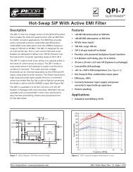
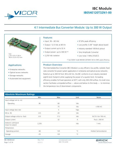
IBC <strong>Module</strong>IB054E120T32N1-004:1 <strong>Intermediate</strong> <strong>Bus</strong> <strong>Converter</strong> <strong>Module</strong>: Up to 300 W OutputFeatures• Input: 36 – 60 Vdc• Output: 12.0 Vdc at 48 Vin• Output current up to 32 A• 97.8% peak efficiency• Low profile: 0.38” height above board• Industry standard 1/8 Brick pinoutSize:2.30 x 0.9 x 0.38 in58,4 x 22,9 x 9,5 mmApplications• Enterprise networks• Optical access networks• Storage networks• Automated test equipment• Output power: up to 300 W [A]• Sine Amplitude <strong>Converter</strong>• 2,250 Vdc isolation• Low noise 1 MHz ZVS/ZCS[A]See 500W model IB054E120T40N1-00 for 98% peak efficiency.Product OverviewThe <strong>Intermediate</strong> <strong>Bus</strong> <strong>Converter</strong> (IBC) <strong>Module</strong> is a very efficient, low profile, isolated, fixedratio converter for power system applications in enterprise and optical access networks.Rated at up to 300 W from 38 to 60 Vin, the IBC conforms to an industry standardeighth brick footprint while supplying the power of a quarter brick. Its leadingefficiency enables full load operation at 65°C with only 200 LFM airflow. Its small crosssection facilitates unimpeded airflow — above and below its thin body — to minimizethe temperature rise of downstream components.Absolute Maximum RatingsInput voltage (+In to –In)Min Max Unit NotesOperating 36 60 Vdc75 Vdc
SPECIFICATIONSAll specifications valid at 48 V IN , 100% rated load and 25°C ambient, unless otherwise indicated.Electrical CharacteristicsIB054E120T32N1-00Attribute Symbol Conditions / Notes Min Typ Max UnitINPUT (Operating from DC input source)Operating input voltage 36 48 60 VdcOperating input surge withstand
IB054E120T32N1-00SPECIFICATIONS (CONT.)All specifications valid at 48 V IN , 100% rated load and 25°C ambient, unless otherwise indicated.Electrical Characteristics (Continued)Attribute Symbol Conditions / Notes Min Typ Max UnitOUTPUT (Continued)Efficiency50% load See figures 1,2 and 3. 97.0 97.4 %Full load See figures 1,2 and 3. 97.4 97.7 %Internal output inductance 1.6 nHInternal output capacitance 55 μFLoad capacitance 0 3000 μFOutput OVP set point <strong>Module</strong> will shutdown 16.2 VdcOutput voltage ripple20 MHz bandwidth, using test circuit inFigure 2360 150 mVp-pOf Iout max., will not shutdown when startedOutput Overload protection threshold into max Cout; and 15% load 105 150 %Auto restart with duty cycle
IB054E120T32N1-00SPECIFICATIONS (CONT.)Control & Interface SpecificationsAttribute Symbol Conditions / Notes Min Typ Max UnitEnable (negative logic)Referenced to –IN<strong>Module</strong> enable threshold 0.8 Vdc<strong>Module</strong> enable current V EN = 0.8 V 130 200 µA<strong>Module</strong> disable threshold 2.4 Vdc<strong>Module</strong> disable current V EN = 2.4 V 130 µADisable hysteresis 500 mVEnable pin open circuit voltage 2.5 3.0 VdcEN to –IN resistance Open circuit, 10 V applied between EN and -IN 35 kΩEnable (positive logic)Referenced to –IN<strong>Module</strong> enable threshold 2.0 2.5 3.0 Vdc<strong>Module</strong> disable threshold 1.45 VdcEN source current (operating) V EN = 5 V 2 mAEN voltage (operating) 4.7 5 5.3 VdcIPC-9592A, Based on Class II Category 2 the following detail is applicable. – Pre-conditioning requiredEnvironmental QualificationTest Description Test Detail Quantity TestedLow Temp 3High Temp 3Rapid Thermal Cycling 35.2.3 HALT (Highly Accelerated Life testing) 6 DOF Random Vibration Test 3Input Voltage Test 3Output Load Test 3Combined Stresses Test 35.2.4 THB (Temp. Humidity Bias) (72 hr presoak required) 1000 hrs – Continuous Bias 305.2.5 HTOB (High Temp. Operating Bias)Power cycle - On 42 minutesOff 1 minute, On 1 minute, Off 1 minute, On 1 minute, Off 1 minute, 30On 1 minute, Off 1 minute, On 1 minute, Off 10 minutes. Alternatingbetween maximum and minimum operating Voltage every hour.5.2.6 TC (Temp. Cycling) 700 cycles , 30 minute dwell at each extreme – 20C minimum ramp rate. 305.2.7 Power Cycling Reference IPC-9592A 3Random Vibration – Operating IEC 60068-2-64 (normal operation vibration) 3Random Vibration Non-operating (transportation) IEC 60068-2-64 35.2.8 – 5.2.13 Shock and Vibration Shock Operating - normal operation shock IEC 60068-2-27 3Free fall - IEC 60068-2-32 3Drop Test 1 full shipping container (box) 125.2.14 Other Environmental Tests5.2.14.1 Corrosion Resistance – Not required N/A5.2.14.2 Dust Resistance – Unpotted class II GR-1274-CORE 35.2.14.3 SMT Attachment Reliability IPC-9701 - J-STD-002 35.2.14.4 Through Hole solderability – J-STD-002 5ESD Classification Testing Sample size assumes CDM testing 12Total Quantity 161IBC MODULE Rev 1.4 vicorpower.comPage 4 of 14 8/2013 800 735.6200
IB054E120T32N1-00SPECIFICATIONS (CONT.)WAVEFORMS (CONT.)Figure 7 — Turn on delay time;Enable turn on delay at nominal line, 15% loadFigure 8 — Output voltage rise time at nominal line, 10% loadFigure 9 — Overshoot at turn on at nominal line, 15% loadFigure 10 — Undershoot at turn off at nominal line, 10% loadFigure 11 — Load transient response; nominal lineLoad step 75–100%; 20 A/divFigure 12 — Load transient response; Full load to 75%; nominal lineIBC MODULE Rev 1.4 vicorpower.comPage 6 of 14 8/2013 800 735.6200
IB054E120T32N1-00SPECIFICATIONS (CONT.)WAVEFORMS (CONT.)Figure 13 — Load transient response; nominal lineLoad step 0–25%; 10 A/divFigure 14 — Load transient response; 25–0%; nominal lineFigure 15 — Input transient response;Vin step low line to high line at full loadFigure 16 — Output ripple; Nominal line, full loadFigure 17 — Three module parallel array test. Vout change when onemodule is disabled. Nominal Vin, Iout = 80 AFigure 18 — Three module parallel array test. Vout change with twomodules operating and a third module enabled.Nominal Vin, Iout = 80 AIBC MODULE Rev 1.4 vicorpower.comPage 7 of 14 8/2013 800 735.6200
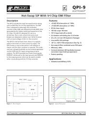
IB054E120T32N1-00SPECIFICATIONS (CONT.)WAVEFORMS (CONT.)35Output Current Derating35Output Current Derating3030Output Current (A)252015105Output Current (A)252015105025 35 45 55 65 75 85 95Ambient Temperature (°C)200 LFM 400 LFM 600 LFMFigure 19 — Maximum output power derating vs ambient air temperature.Transverse airflow, Board and junction temperatures withinIPC-9592 derating guidelines025 35 45 55 65 75 85 95Ambient Temperature (°C)200 LFM 400 LFM 600 LFMFigure 20 — Maximum output power derating vs ambient air temperature.Longitudinal airflow, Board and junction temperatures withinIPC-9592 derating guidelinesVsource+_47 µFCurrent Probe+INEN–INIBC+OUT–OUTLoadC*Vsource+_Current Probe10 µH470 µF+INEN–INIBC+OUT–OUTLoad*Maximum load capacitanceFigure 21 — Inrush current overshootFigure 22 — Input reflected ripple current+INIBC+OUT10 µF 0.1 µFE – Load–IN–OUTCy aCy cCy bCy d20 MHz BWCy a-d = 4700 pFFigure 23 — Test circuit; output voltage rippleIBC MODULE Rev 1.4 vicorpower.comPage 8 of 14 8/2013 800 735.6200
IB054E120T32N1-00SPECIFICATIONS (CONT.)THERMAL DATAFigure 24 — Thermal plot, 200 LFM, 25°C, 48 Vin, 300 W output powerFigure 25 — Thermal plot, 200 LFM, 25°C, 48 Vin, 300 W output powerFigure 26 — Thermal plot, 400 LFM, 25°C, 48 Vin, 300 W output powerFigure 27 — Thermal plot, 400 LFM, 25°C, 48 Vin, 300 W output powerFigure 28 — Thermal plot, 600 LFM, 25°C, 48 Vin, 300 W output powerFigure 29 — Thermal plot, 600 LFM, 25°C, 48 Vin, 300 W output powerIBC MODULE Rev 1.4 vicorpower.comPage 9 of 14 8/2013 800 735.6200
IB054E120T32N1-00PIN / CONTROL FUNCTIONS+In / -In – DC Voltage Input PinsThe IBC input voltage range should not be exceeded. An internalundervoltage/overvoltage lockout function prevents operation outside ofthe normal operating input range. The IBC turns on within an input voltagewindow bounded by the “Input under-voltage turn-on” and “Inputover-voltage turn-off” levels, as specified. The IBC may be protected againstaccidental application of a reverse input voltage by the addition of arectifier in series with the positive input, or a reverse rectifier in shunt withthe positive input located on the load side of the input fuse.The connection of the IBC to its power source should be implemented withminimal distribution inductance. If the interconnect inductance exceeds100 nH, the input should be bypassed with a RC damper to retain lowsource impedance and stable operation. With an interconnect inductanceof 200 nH, the RC damper may be 47 μF in series with 0.3 Ω. A singleelectrolytic or equivalent low-Q capacitor may be used in place of the seriesRC bypass.EN - Enable/DisableNegative Logic OptionIf the EN port is left floating, the IBC output is disabled. Once this port ispulledlower than 0.8 Vdc with respect to –In, the output is enabled. TheEN port can be driven by a relay, opto-coupler, or open collector transistor.Refer to Figures 6 and 7 for the typical enable / disable characteristics. Thisport should not be toggled at a rate higher than 1 Hz. The EN port shouldalso not be driven by or pulled up to an external voltage source.123Top ViewFigure 30 — IBC Pin DesignationsPinFunction1 Vin+2 Enable3 Vin-4 Vout-5 Vout+54Positive Logic OptionIf the EN port is left floating, the IBC output is enabled. Once this port ispulled lower than 1.4 Vdc with respect to –In, the output is disabled. Thisaction can be realized by employing a relay, opto-coupler, or open collectortransistor. This port should not be toggled at a rate higher than 1 Hz.The EN port should also not be driven by or pulled up to an external voltagesource. The EN port can source up to 2 mA at 5 Vdc. The EN portshould never be used to sink current.If the IBC is disabled using the EN pin, the module will attempt to restartapproximately every 250ms. Once the module has been disabled for at least250ms, the turn on delay after the EN pin is enabled will be as shown inFigure 7.+Out / -Out – DC Voltage Output PinsTotal load capacitance at the output of the IBC should not exceed thespecified maximum. Owing to the wide bandwidth and low outputimpedance of the IBC, low frequency bypass capacitance and significantenergy storage may be more densely and efficiently provided by addingcapacitance at the input of the IBC.IBC MODULE Rev 1.4 vicorpower.comPage 10 of 14 8/2013 800 735.6200
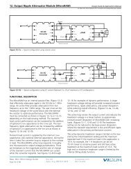
IB054E120T32N1-00APPLICATIONS NOTEParallel OperationThe IBC will inherently current share when operated in an array. Arrays maybe used for higher power or redundancy in an application. Current sharingaccuracy is maximized when the source and load impedance presented toeach IBC within an array are equal. The recommended method to achievematched impedances is to dedicate common copper planes within the PCBto deliver and return the current to the array, rather than rely upon tracesof varying lengths. In typical applications the current being delivered to theload is larger than that sourced from the input, allowing narrower traces tobe utilized on the input side if necessary. The use of dedicated powerplanes is, however, preferable.One or more IBCs in an array may be disabled without adversely affectingoperation or reliability as long as the load does not exceed the rated powerof the enabled IBCs.The IBC power train and control architecture allow bi-directional powertransfer, including reverse power processing from the IBC output to itsinput. The IBC’s ability to process power in reverse improves the IBC transientresponse to an output load dump.Thermal ConsiderationsThe temperature distribution of the VI Brick can vary significantlywith its input/output operating conditions, thermal management andenvironmental conditions. Although the PCB is UL rated to 130°C, it isrecommended that PCB temperatures be maintained at or below 125°C.For maximum long term reliability, lower PCB temperatures arerecommended for continuous operation, however, short periods ofoperation at 125°C will not negatively impact performance or reliability.WARNING: Thermal and voltage hazards. The IBC can operate with surfacetemperatures and operating voltages that may be hazardous to personnel.Ensure that adequate protection is in place to avoid inadvertent contact.Input Impedance RecommendationsTo take full advantage of the IBC capabilities, the impedance presented toits input terminals must be low from DC to approximately 5 MHz.The source should exhibit low inductance and should have a criticallydamped response. If the interconnect inductance is excessive, the IBC inputpins should be bypassed with an RC damper (e.g., 47 μF in series with0.3 Ω) to retain low source impedance and proper operation. Given thewide bandwidth of the IBC, the source response is generally the limitingfactor in the overall system response.Anomalies in the response of the source will appear at the output of theIBC multiplied by its K factor. The DC resistance of the source should bekept as low as possible to minimize voltage deviations. This is especiallyimportant if the IBC is operated near low or high line as theovervoltage/undervoltage detection circuitry could be activated.Input Fuse RecommendationsThe IBC is not internally fused in order to provide flexibility in configuringpower systems. However, input line fusing of VI Bricks must always beincorporated within the power system. A fast acting fuse should be placedin series with the +In port. See safety agency approvals.Application NotesFor IBC and VI Brick application notes on soldering, thermal management,board layout, and system design visit vicorpower.com.PART NUMBERINGProduct InputNominal Temperature Output Enable PinFamily Voltage Package Output Voltage Grade Current Logic LengthOptionsIB 054 E 120 T 32 N = Negative 1 = 0.145 -00 = Open frameP = Positive 2 = 0.210IBC MODULE Rev 1.4 vicorpower.comPage 11 of 14 8/2013 800 735.6200
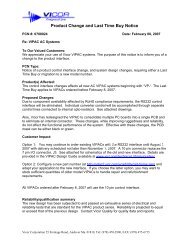
IB054E120T32N1-00+IN-INENC INUVLOOVLOSensingControllerSwitchingRegulatorVBCr LrCurrentSenseReverseCurrentProtectionC OUT+OUT-OUT⎺IBC BLOCK DIAGRAMThe Sine Amplitude <strong>Converter</strong> TM (SAC TM ) uses a high frequency resonant tank to transfer energy from input to output. The resonant tank is formed by Cr andleakage inductance from the main transformer, Lr, as shown in the block diagram. The controller regulates switching frequency of the FET drivers, monitorscurrent sensing, and provides undervoltage and overvoltage protection.VoltageSenseV2 (VCC)CurrentSenseQQFET DriveTransformerPrimaryFET DriveTransformerSecondaryIBC Block DiagramResonantTankFET DriveTransformerPrimaryFET DriveTransformerSecondaryPrimarySecondaryIsolationBarrierMainTransformerCurrentTransformerFET DriveTransformerSecondaryFigure 31 — IBC Block diagramIBC MODULE Rev 1.4 vicorpower.comPage 12 of 14 8/2013 800 735.6200
IB054E120T32N1-00<strong>Vicor</strong>’s comprehensive line of power solutions includes high density AC-DC and DC-DC modules and accessorycomponents, fully configurable AC-DC and DC-DC power supplies, and complete custom powersystems.Information furnished by <strong>Vicor</strong> is believed to be accurate and reliable. However, no responsibility is assumed by <strong>Vicor</strong> for its use. <strong>Vicor</strong> makes norepresentations or warranties with respect to the accuracy or completeness of the contents of this publication. <strong>Vicor</strong> reserves the right to makechanges to any products, specifications, and product descriptions at any time without notice. Information published by <strong>Vicor</strong> has been checked andis believed to be accurate at the time it was printed; however, <strong>Vicor</strong> assumes no responsibility for inaccuracies. Testing and other quality controls areused to the extent <strong>Vicor</strong> deems necessary to support <strong>Vicor</strong>’s product warranty. Except where mandated by government requirements, testing of allparameters of each product is not necessarily performed.Specifications are subject to change without notice.<strong>Vicor</strong>’s Standard Terms and ConditionsAll sales are subject to <strong>Vicor</strong>’s Standard Terms and Conditions of Sale, which are available on <strong>Vicor</strong>’s webpage or upon request.Product WarrantyIn <strong>Vicor</strong>’s standard terms and conditions of sale, <strong>Vicor</strong> warrants that its products are free from non-conformity to its Standard Specifications (the “ExpressLimited Warranty”). This warranty is extended only to the original Buyer for the period expiring two (2) years after the date of shipment and isnot transferable.UNLESS OTHERWISE EXPRESSLY STATED IN A WRITTEN SALES AGREEMENT SIGNED BY A DULY AUTHORIZED VICOR SIGNATORY, VICOR DISCLAIMSALL REPRESENTATIONS, LIABILITIES, AND WARRANTIES OF ANY KIND (WHETHER ARISING BY IMPLICATION OR BY OPERATION OF LAW) WITH RE-SPECT TO THE PRODUCTS, INCLUDING, WITHOUT LIMITATION, ANY WARRANTIES OR REPRESENTATIONS AS TO MERCHANTABILITY, FITNESS FORPARTICULAR PURPOSE, INFRINGEMENT OF ANY PATENT, COPYRIGHT, OR OTHER INTELLECTUAL PROPERTY RIGHT, OR ANY OTHER MATTER.This warranty does not extend to products subjected to misuse, accident, or improper application, maintenance, or storage. <strong>Vicor</strong> shall not be liablefor collateral or consequential damage. <strong>Vicor</strong> disclaims any and all liability arising out of the application or use of any product or circuit and assumesno liability for applications assistance or buyer product design. Buyers are responsible for their products and applications using <strong>Vicor</strong> products andcomponents. Prior to using or distributing any products that include <strong>Vicor</strong> components, buyers should provide adequate design, testing and operatingsafeguards.<strong>Vicor</strong> will repair or replace defective products in accordance with its own best judgment. For service under this warranty, the buyer must contact<strong>Vicor</strong> to obtain a Return Material Authorization (RMA) number and shipping instructions. Products returned without prior authorization will be returnedto the buyer. The buyer will pay all charges incurred in returning the product to the factory. <strong>Vicor</strong> will pay all reshipment charges if the productwas defective within the terms of this warranty.Life Support PolicyVICOR’S PRODUCTS ARE NOT AUTHORIZED FOR USE AS CRITICAL COMPONENTS IN LIFE SUPPORT DEVICES OR SYSTEMS WITHOUT THE EXPRESSPRIOR WRITTEN APPROVAL OF THE CHIEF EXECUTIVE OFFICER AND GENERAL COUNSEL OF VICOR CORPORATION. As used herein, life support devicesor systems are devices which (a) are intended for surgical implant into the body, or (b) support or sustain life and whose failure to performwhen properly used in accordance with instructions for use provided in the labeling can be reasonably expected to result in a significant injury to theuser. A critical component is any component in a life support device or system whose failure to perform can be reasonably expected to cause thefailure of the life support device or system or to affect its safety or effectiveness. Per <strong>Vicor</strong> Terms and Conditions of Sale, the user of <strong>Vicor</strong> productsand components in life support applications assumes all risks of such use and indemnifies <strong>Vicor</strong> against all liability and damages.Intellectual Property Notice<strong>Vicor</strong> and its subsidiaries own Intellectual Property (including issued U.S. and Foreign Patents and pending patent applications) relating to the productsdescribed in this data sheet. No license, whether express, implied, or arising by estoppel or otherwise, to any intellectual property rights isgranted by this document. Interested parties should contact <strong>Vicor</strong>'s Intellectual Property Department.The products described on this data sheet are protected by the following U.S. Patents Numbers:5,945,130; 6,403,009; 6,710,257; 6,911,848; 6,930,893; 6,934,166; 6,940,013; 6,969,909; 7,038,917;7,166,898; 7,187,263; 7,361,844; D496,906; D505,114; D506,438; D509,472; and for use under 6,975,098 and 6,984,965.<strong>Vicor</strong> Corporation25 Frontage RoadAndover, MA, USA 01810Tel: 800-735-6200Fax: 978-475-6715emailCustomer Service: custserv@vicorpower.comTechnical Support: apps@vicorpower.comIBC MODULE Rev 1.4 vicorpower.comPage 14 of 14 8/2013 800 735.6200