DEEP SEA ELECTRONICS PLC
DEEP SEA ELECTRONICS PLC
DEEP SEA ELECTRONICS PLC

Create successful ePaper yourself
Turn your PDF publications into a flip-book with our unique Google optimized e-Paper software.
DSE Model 5220 Automatic Mains Failure & Instrumentation System Operators ManualDeep Sea Electronics PlcHighfield HouseHunmanbyNorth YorkshireYO14 0PHENGLANDSales Tel: +44 (0) 1723 890099Sales Fax: +44 (0) 1723 893303E-mail: sales@Deepseaplc.comWebsite: www.deepseaplc.comDSE Model 5220 Control and Instrumentation System Operators Manual© Deep Sea Electronics PlcAll rights reserved. No part of this publication may be reproduced in any material form (including photocopying or storing in anymedium by electronic means or other) without the written permission of the copyright holder except in accordance with theprovisions of the Copyright, Designs and Patents Act 1988.Applications for the copyright holder’s written permission to reproduce any part of this publication should be addressed to DeepSea Electronics Plc at the address above.Any reference to trademarked product names used within this publication is owned by their respective companies.Deep Sea Electronics Plc reserves the right to change the contents of this document without prior notice.2 057-012 5220 OPERATING MANUAL ISSUE 5.1 18/06/2007 AM
DSE Model 5220 Automatic Mains Failure & Instrumentation System Operators ManualWhether the start sequence is initiated by mains (utility failure) or by remote start input, the follow sequence isfollowed :To allow for short term mains supply transient conditions or false remote start signals, the Start Delay timer isinitiated. After this delay, if the pre-heat output option is selected then the pre-heat timer is initiated, and thecorresponding auxiliary output (if configured) will energise.NOTE:- If the mains supply returns within limits, ( or the Remote Start signal is removed if the startsequence was initiated by remote start) during the Start Delay timer, the unit will return to a stand-bystate.After the above delays the Fuel Solenoid is energised, then one second later, the Starter Motor is engaged.The engine is cranked for a pre-set time period. If the engine fails to fire during this cranking attempt then thestarter motor is disengaged for the pre-set rest period. Should this sequence continue beyond the set number ofattempts, the start sequence will be terminated andFail to Start fault will be displayed accompanied by a flashing shutdown symbol.When the engine fires, the starter motor is disengaged and locked out at a pre-set frequency from the Alternatoroutput. Alternatively a Magnetic Pickup mounted on the flywheel housing can be used for speed detection (This isselected by PC using the 5200 series configuration software). Rising oil pressure can also be used to disconnectthe starter motor, however it cannot be used for underspeed or overspeed detection.After the starter motor has disengaged, the Safety On timer is activated, allowing Oil Pressure, High EngineTemperature, Under-speed, Charge Fail and any delayed Auxiliary fault inputs to stabilise without triggering thefault.Once the engine is running, the Warm Up timer, if selected is initiated, allowing the engine to stabilise beforeaccepting the load.If an auxiliary output has been selected to give a load transfer signal, this would then activate.NOTE:-A load transfer will not be initiated until the Oil Pressure has risen. Thus preventingexcessive wear on the engine.On the return of the mains supply, (or removal of the Remote Start signal if the set was started by remote signal) ,the Stop delay timer is initiated, once it has timed out, the load Transfer signal is de-energised, removing the load.The Cooling timer is then initiated, allowing the engine a cooling down period off load before shutting down. Oncethe Cooling timer expires the Fuel Solenoid is de-energised, bringing the generator to a stop.Should the mains supply fall outside limits again (or the Remote Start signal is re-activated) during the coolingdown period, the generating set will return to a on load condition.5220 OPERATING MANUAL ISSUE 5.1 18-Jun-07 AM 7
3.2 MANUAL OPERATIONDSE Model 5220 Automatic Mains Failure & Instrumentation System Operators ManualNOTE:- If a digital input configured to panel lock is active, the LCD will display the icon. When inpanel lock, changing module modes will not be possible. Viewing the instruments and event logsis NOT affected by panel lock.To initiate a start sequence in MANUAL, press the pushbutton. When the controller is in the manual mode(indicated by an LED indicator beside the button), pressing the START (I) button will initiate the start sequence.NOTE:- There is no Start Delay in this mode of operation.If the pre-heat output option is selected this timer is then initiated, and the auxiliary output selected is energised.The Fuel Solenoid is energised, then the Starter Motor is engaged.The engine is cranked for a pre-set time period. If the engine fails to fire during this cranking attempt then thestarter motor is disengaged for the pre-set rest period. Should this sequence continue beyond the set number ofattempts, the start sequence will be terminated and Fail to Startfault will be displayed accompanied by aflashing shutdownindicator.When the engine fires, the starter motor is disengaged and locked out at a pre-set frequency from the Alternatoroutput. Alternatively a Magnetic Pickup mounted on the flywheel housing can be used for speed detection (This isselected by PC using the 5200 series configuration software). Rising oil pressure can also be used to disconnectthe starter motor, however it cannot be used for underspeed or overspeed detection.After the starter motor has disengaged, the Safety On timer is activated, allowing Oil Pressure, High EngineTemperature, Under-speed, Charge Fail and any delayed Auxiliary fault inputs to stabilise without triggering thefault.Once the engine is running, the Warm Up timer, if selected, is initiated, allowing the engine to stabilise before itcan be loaded.The generator will run off load, unless the mains supply fails or a Remote Start on load signal is applied. If Closegenerator has been selected as a control source, the appropriate auxiliary output will then activate.The generator will continue to run On load regardless of the state of the mains supply or remote start input until theAuto mode is selected.If Auto mode is selected, and the mains supply is healthy with the remote start on load signal not active, then theRemote Stop Delay Timer begins, after which, the load is disconnected. The generator will then run off loadallowing the engine a cooling down period.Selecting STOP (O) de-energises the FUEL SOLENOID, bringing the generator to a stop.8 057-012 5220 OPERATING MANUAL ISSUE 5.1 18/06/2007 AM
3.3 TEST OPERATIONDSE Model 5220 Automatic Mains Failure & Instrumentation System Operators ManualNOTE:- If a digital input configured to panel lock is active, the LCD will display the icon. When inpanel lock, changing module modes will not be possible. Viewing the instruments and event logsis NOT affected by panel lock.To initiate a start sequence in TEST, press the pushbutton. When the controller is in the test mode (indicatedby an LED indicator beside the button), pressing the START (I) button will initiate the start sequence.NOTE:- There is no Start Delay in this mode of operation.If the pre-heat output option is selected this timer is then initiated, and the auxiliary output selected is energised.After the above delay the Fuel Solenoid is energised, then the Starter Motor is engaged.The engine is cranked for a pre-set time period. If the engine fails to fire during this cranking attempt then thestarter motor is disengaged for the pre-set rest period. Should this sequence continue beyond the set number ofattempts, the start sequence will be terminated and Fail to Startfault will be displayed accompanied by aflashing shutdownindicator.When the engine fires, the starter motor is disengaged and locked out at a pre-set frequency from the Alternatoroutput. Alternatively a Magnetic Pickup mounted on the flywheel housing can be used for speed detection (This isselected by PC using the 5200 series configuration software). Rising oil pressure can also be used to disconnectthe starter motor, however it cannot be used for underspeed or overspeed detection.After the starter motor has disengaged, the Safety On timer is activated, allowing Oil Pressure, High EngineTemperature, Under-speed, Charge Fail and any delayed Auxiliary fault inputs to stabilise without triggering thefault.Once the engine is running, the Warm Up timer, if selected, is initiated, allowing the engine to stabilise before itcan be loaded.The generator will continue to run On load regardless of the state of the mains supply or remote start input until theAuto mode is selected.If Auto mode is selected, and the mains supply is healthy with the remote start on load signal not active, then theRemote Stop Delay Timer begins, after which, the load is disconnected. The generator will then run off loadallowing the engine a cooling down period.Selecting STOP (O) removes the Close Generator output (if configured) and de-energises the FUEL SOLENOID,bringing the generator to a stop.5220 OPERATING MANUAL ISSUE 5.1 18-Jun-07 AM 9
DSE Model 5220 Automatic Mains Failure & Instrumentation System Operators Manual4 PROTECTIONSThe module will indicate that an alarm has occurred in several ways;The LCD display will indicate a ‘common alarm’ either :(warning),(shutdown) orIf appropriate, the LCD display or LED indicators will display theappropriate alarm icon i.e. for battery charging failure :(electrical trip)NOTE:- Alarm icons in the LED display area are ‘hid until lit’. This means that the display areaappears totally clear, and ‘free from clutter’. The advantage of this is that when an alarm does occur,the respective LED icon will illuminate on the otherwise blank fascia. This makes alarm identificationmuch clearer.If no alarms are present the LCDwill extinguish any alarm icons.In the event of a warning alarm the LCD will display the appropriate icon. If a shutdown then occurs the modulewill display the appropriate icon. The original warning alarm icon will remain displayed.Example:-Low battery volts warning (all symbols steady)Followed by….Low battery volts warning indicator stillpresent, common alarm indicator haschanged to a shutdown symbol and isnow flashing.Also present is the flashing underspeedLED.Underspeed and Shutdown alarm Icons are displayed flashing. The original warning will remain displayed as longat the triggering conditions remain. Any subsequent warnings or shutdowns that occur will be displayed steady,therefore only the first-up shutdown will appear flashing.10 057-012 5220 OPERATING MANUAL ISSUE 5.1 18/06/2007 AM
DSE Model 5220 Automatic Mains Failure & Instrumentation System Operators Manual4.1 WARNINGSWarnings are non-critical alarm conditions and do not affect the operation of the generator system, they serve todraw the operators attention to an undesirable condition.In the event of a warning alarm the LCD will display:-BATTERY CHARGE FAILURE, if the module does not detect a voltage from the warning light terminal on theauxiliary charge alternator the icon will illuminate.BATTERY LOW VOLTAGE, if the module detects that the plant DC supply has fallen below the low volts settinglevel, the module will display:-VThe Battery Low Voltage alarm is delayed by the Low DC Volts Delay timer.BATTERY HIGH VOLTAGE, if the module detects that the plant DC supply has risen above the high volts settinglevel, the module will display:-VThe Battery High Voltage alarm is delayed by the High DC Volts Delay timer.FAIL TO STOP, If the module detects the engine is still running when the ‘Fail to stop timer’ expires, then themodule will display:-NOTE:- ‘Fail to Stop’ could indicate a faulty oil pressure sender - If engine is at rest check oil senderwiring and configuration.AUXILIARY INPUTS, if an auxiliary input has been configured as a warning the appropriate LCD segment will bedisplayed:-!LOW FUEL LEVEL. If the fuel level detected by the fuel level sender falls below the low fuel level setting, awarning will occur.Theicon will illuminate.4.2 ANALOGUE PRE-ALARMSThe following alarms are termed ‘pre-alarms’ as they pre warn the operator of a potentially more serious alarmcondition. For instance, if the engine temperature rises past the pre alarm level, a warning condition will occur tonotify the operator. If the temperature falls below this level, then the alarm ceases, and the set will continue to runas normal. However if the temperature continues to rise until the coolant temperature trip point is reached, thewarning is escalated and a high coolant temperature shutdown is initiated.During a pre-alarm condition, the warning symbolicon:is displayed on the LCD display, along with the appropriateLOW OIL PRESSURE, if the module detects that the engine oil pressure has fallen below the low oil pressure prealarmsetting level after the Safety On timer has expired, a warning will occur.The icon will illuminate.5220 OPERATING MANUAL ISSUE 5.1 18-Jun-07 AM 11
DSE Model 5220 Automatic Mains Failure & Instrumentation System Operators Manual4.4 SHUTDOWNSShutdowns are latching and stop the Generator. The alarm must be cleared, and the fault removed to reset themodule.In the event of a shutdown alarm the LCD will display:-(flashing).The appropriate icon will also be displayed flashingNOTE:- The alarm condition must be rectified before a reset will take place. If the alarm conditionremains it will not be possible to reset the unit (The exception to this is the Low Oil Pressure alarm andsimilar ‘delayed alarms’, as the oil pressure will be low with the engine at rest). Any subsequentwarnings or shutdowns that occur will be displayed steady, therefore only the first-up shutdown willappear flashing.FAIL TO START, if the engine does not fire after the pre-set number of attempts has been made a shutdown willbe initiated.The icon will illuminate.EMERGENCY STOP, removal of the positive DC Supply from the Emergency Stop input initiates the followingsequence, firstly it will initiate a controlled shutdown of the Generator and prevent any attempt to restart theGenerator until the Emergency Stop push-button has been reset. Secondly it removes the positive DC supply fromboth the Fuel Solenoid and Starter Solenoid.The icon will illuminate.NOTE:- The Emergency Stop positive signal must be present otherwise the unit will shutdown.LOW OIL PRESSURE, if the module detects that the engine oil pressure has fallen below the low oil pressure tripsetting level after the Safety On timer has expired, a shutdown will occur.The icon will illuminate.HIGH ENGINE TEMPERATURE if the module detects that the engine coolant temperature has exceeded the highengine temperature trip setting level after the Safety On timer has expired, a shutdown will occur.The icon will illuminate.OVERSPEED, if the engine speed exceeds the pre-set trip a shutdown is initiated.The icon will illuminate.Overspeed is not delayed, it is an immediate shutdown.NOTE:-During the start-up sequence the overspeed trip logic can be configured to allow an extratrip level margin. This is used to prevent nuisance tripping on start-up - Refer to the 5200 seriesconfiguration software manual under heading ‘Overspeed Overshoot’ for details.UNDERSPEED, if the engine speed falls below the pre-set trip after the Safety On timer has expired, a shutdown isinitiated.The icon will illuminate.5220 OPERATING MANUAL ISSUE 5.1 18-Jun-07 AM 13
DSE Model 5220 Automatic Mains Failure & Instrumentation System Operators ManualGENERATOR HIGH FREQUENCY if the module detects a generator output frequency in excessof the pre-set trip a shutdown is initiated.The icon will illuminate.Generator High Frequency is not delayed, it is an immediate shutdown.GENERATOR LOW FREQUENCY, if the module detects a generator output frequency below thepre-set trip after the Safety On timer has expired, a shutdown is initiated.Theicon will illuminate.GENERATOR HIGH VOLTAGE if the module detects a generator output voltage in excess of the pre-set trip ashutdown is initiated.The V icon will illuminate.High voltage is not delayed, it is an immediate shutdown.GENERATOR LOW VOLTAGE if the module detects a generator output voltage below the below the pre-set tripafter the Safety On timer has expired, a shutdown is initiated.The V icon will illuminate.OIL PRESSURE SENDER OPEN CIRCUIT, if the module detects a loss of signal from the oil pressure sender(open circuit) a shutdown is initiated. The LCD will indicate:-(Steady) (And ‘-----‘ on the engine oil pressure instrument). Sender failure is not delayed, it is an immediateshutdown.AUXILIARY INPUTS, if an auxiliary input has been configured as a shutdown the appropriate LCD segment will bedisplayed:-!LOSS OF SPEED SIGNAL, if the speed sensing signal is lost during cranking, a shutdown is initiated.The icon will illuminate. (Steady) (And ‘-----‘ on the engine RPM instrument).NOTE:- This will only occur if the speed sensing signal is lost during cranking or during the safetyon timer. If the signal is lost during normal operation the Generator will shutdown with an Under-speedalarm.14 057-012 5220 OPERATING MANUAL ISSUE 5.1 18/06/2007 AM
DSE Model 5220 Automatic Mains Failure & Instrumentation System Operators Manual5 LCD INDICATORS AND LOGO INSERTUSER CONFIGURABLE LCD indicatorsThese indicators can be configured by the user to indicate any one of 100+ different functionsbased around the following:-• INDICATIONS - Monitoring of a digital input and indicating associated functioning user’sequipment - Such as Battery Charger On or Louvre Open, etc.• WARNINGS and SHUTDOWNS - Specific indication of a particular warning or shutdowncondition, backed up by LCD indication - Such as Low Oil Pressure Shutdown, LowCoolant level, etc.• STATUS INDICATIONS - Indication of specific functions or sequences derived from themodules operating state - Such as Safety On, Pre-heating, Panel Locked, GeneratorAvailable, etc.These indicators are annunciated using a removable insert card. Additionally the module’s logocan be changed to suit generator manufacturer’s requirements. This can be used for instance togive custom branding to the module, or even include the service telephone number.DSE have produced the ‘insert card creator’ software, shipped with the DSE Software CD to easethe production of text and logo insert cards to suit your application.Removal and insertion of the text insert cardRemoval and insertion of the Logo insert card16 057-012 5220 OPERATING MANUAL ISSUE 5.1 18/06/2007 AM
DSE Model 5220 Automatic Mains Failure & Instrumentation System Operators Manual6 DESCRIPTION OF CONTROLSThe following section details the function and meaning of the various controls on the module.ScrollConfigure/ logStop Manual Test Auto StartFIG25220 OPERATING MANUAL ISSUE 5.1 18-Jun-07 AM 17
DSE Model 5220 Automatic Mains Failure & Instrumentation System Operators Manual6.1 TYPICAL LCD DISPLAY SCREENSINSTRUMENTSThe LCD displays the various engine parameters such as‘ENGINE SPEED’, ‘OIL PRESSURE’, ‘HOURS RUN’, etc.Each instrument is displayed with the appropriate units of measure.In this example, the values being displayed are Generatorphase to neutral L1-N, AC voltages V.STATUS ICONSUSER DEFINEDINDICATIONSThe LCD also displays the status of the controller by showing (forexample) an hourglass symbol when a timer is in progress or bydisplaying a common alarm symbol. This display is indicating that atimer is in progress and a warning alarm is present. See the‘Protections’ section of this manual for details of the alarms.In this example the values being displayed are the threegenerator AC currents AThe LCD displays the user-defined indications when configuredand active. The icons will illuminate and point to the appropriatetext insert label. These indications can be used to indicate theoperation of external equipment (i.e. ‘Battery Charger On’, ‘BreakerClosed’ etc) or to indicate internal states (i.e. Engine Running,Safety On, etc).USER DEFINED ALARMSThe LCD displays the user-defined alarms when configured andactive. The icons will illuminate and point to the appropriate textinsert label. These alarms can be used to indicate the operation ofexternal alarms (i.e. ‘Low Fuel Level’, ‘Low Coolant level’ etc) or toindicate internal alarms (i.e. Fail to Stop, MPU fault, etc).HOURS RUN COUNTERThe LCD displays the generator hours run time while both thegenerator symbol and the clock symbol are present.In this example the hours run time would read 21 hours and 35minutes.HOURS RUN (100 hrs +)The hours run up to and including 99 are displayed on the third lineof the display. Minutes run are displayed after the decimal point.All hours above 99, (i.e. the hundreds, thousands and tens ofthousands units) are displayed on the second line of the display.In this example the hours run time would read 221 hours and 35minutes.HOURS RUN (1000 hrs +)All hours above 99, (i.e. the hundreds, thousands and tens ofthousands units) are displayed on the second line of the display.In this example the hours run time would read 3221 hours and 35minutes.18 057-012 5220 OPERATING MANUAL ISSUE 5.1 18/06/2007 AM
6.2 LCD DISPLAY AREASDSE Model 5220 Automatic Mains Failure & Instrumentation System Operators ManualInstrument valuesDisplay information &units of measureAlarm iconsStatus iconsUser configurable displayicons5220 OPERATING MANUAL ISSUE 5.1 18-Jun-07 AM 19
DSE Model 5220 Automatic Mains Failure & Instrumentation System Operators Manual6.3 VIEWING THE INSTRUMENTSIt is possible to manually scroll to display the different instruments by repeatedly operating the scroll button. Onceselected the instrument will remain on the LCD display until the user selects a different instrument or after a periodof inactivity the module will revert to the initial display (Hz/RPM).Instrument Page Order:-• Generator RPM / Frequency (Hz)• Generator AC Voltage Line-Neutral• Generator AC Voltage Line-Line• Oil Pressure• Coolant temperature• Fuel level (%)• Engine Hours Run• DC Battery Voltage• AC Line Current• Total kW• Total VA• AC phase angle (cos ∅)• Mains (Utility) Frequency (Hz)• Mains (Utility) AC Voltage Line-Neutral• Mains (Utility) AC Voltage Line-LineManually Selecting an InstrumentInitial display (Hz/RPM)Pressing the DOWN button the LCD willthen show (Generator L-N voltages)Pressing the DOWN button the LCD willthen show (Generator L-L voltages)Pressing the button again will scroll through each individual instrument eventually returning to the originalinstrument displayed.NOTE:-Once selected the instrument will remain on the LCD display until the user selects a differentinstrument or after a period of inactivity the module will revert to the initial display.20 057-012 5220 OPERATING MANUAL ISSUE 5.1 18/06/2007 AM
DSE Model 5220 Automatic Mains Failure & Instrumentation System Operators Manual6.4 VIEWING THE EVENT LOGThe model 5220 remote start module maintainsa log of the last 15 shutdown alarms and mainsfail/returns to enable the operator or engineer toview the past alarms history. Only shutdownand electrical trip alarms are logged; warningalarms are not logged. Once the log is full (15shutdown alarms), any subsequent shutdownalarms will overwrite the oldest entry in the log.Hence the log will always contain the 15 mostrecent shutdown alarms.The alarm is logged, along with the date andtime of the event in the format shown in thisexample.To view the event log, press the log button . The LCD display will flash the log symbol to confirm thatthe event log has been entered.In this example, the oil can symbol representsan oil pressure shutdown, backed up by theflashing shutdown symbol in the LCD display.The value displayed means that the oil pressureshutdown occurred on November 1 st 2002 at8:17.Press downto view the next most recent shutdown alarm:In this example, the hand/button symbolrepresents an emergency stop shutdown,backed up by the flashing shutdown symbol inthe LCD display.The value displayed means that the emergencystop button was pressed on November 1 st 2002at 11:50.Mains Failure is logged using a flashing symbol.Mains Return is logged by illuminating the mains available LED.Continuing to press down will cycle through the past alarms until all 15 logged alarms have been viewed,after which the most recent alarm will again be showed and the cycle will begin again.To exit the event log and return to viewing the instruments, press the logbutton.5220 OPERATING MANUAL ISSUE 5.1 18-Jun-07 AM 21
DSE Model 5220 Automatic Mains Failure & Instrumentation System Operators Manual6.5 INDICATORSCOMMON ALARM LCD indicatorsThese indicate when an alarm condition is present. The Alarm icons orLEDs will detail the exact nature of the alarm. (warning) or (shutdown)USER CONFIGURABLE LCD INDICATORSThese LCD’s can be configured by the user to indicate any on of thedifferent functions based around the following:-• INDICATIONS - Monitoring of a digital input and indicatingassociated functioning user’s equipment - Such as Battery ChargerOn or Louvres Open, etc.• WARNINGS and SHUTDOWNS - Specific indication of a particularwarning or shutdown condition, backed up by LCD indication (!)-Such as Low Oil Pressure Shutdown, Low Coolant level, etc.• STATUS INDICATIONS - Indication of specific functions orsequences derived from the modules operating state - Such asSafety On, Pre-heating, Generator Available, etc.6.6 CONTROLSSTOP/RESETThis button places the module into its Stop/reset mode. This will clear any alarm conditions forwhich the triggering criteria have been removed. If the engine is running and this position isselected, the module will automatically instruct the changeover device to un-load the generator(‘Load transfer’ becomes inactive (if used)). The fuel supply will be removed and engine will bebrought to a standstill. Should a remote start signal be present while operating in this mode, aremote start will not occur.MANUALThis mode is used to allow manual control of the generator functions. Once in Manual mode themodule will respond to the start (I) button and start the engine and run off load. If the engine isrunning off-load in the Manual mode and a remote start signal becomes present, the module willautomatically instruct the changeover device to place the generator on load (‘Load transfer’becomes active (if used)). Should the remote start signal then be removed the generator willremain on load until either the ‘STOP/RESET’ or ‘AUTO’ positions is selected.AUTOThis button places the module into its ‘Automatic’ mode. This mode allows the module to controlthe function of the generator automatically. The module will monitor the remote start input andonce a start condition is signalled the set will be automatically started and placed on load (‘Loadtransfer’ becomes active (if used)). If the starting signal is removed the module will automaticallytransfer the load from the generator and shut the set down observing the stop delay timer andcooling timer as necessary. The module will then await the next start event. For further detailsplease see the more detailed description of ‘Auto Operation’ earlier in this manual.TESTThis button places the module into its ‘Test’ mode. This mode allows the operator to perform an ‘onload’ test of the system. Once in Test mode the module will respond to the start (I) button and startthe engine and run on load (‘Load transfer’ becomes active (if used)). The generator will continueto run on load until Auto mode is selected. Then, If the starting signal is removed the module willautomatically transfer the load from the generator and shut the set down observing the stop delaytimer and cooling timer as necessary. The module will then await the next start event.For further details please see the more detailed description of ‘Test Operation’ earlier in this manual.STARTThis button is only active in MANUAL or TEST mode. Pressing this button in manual ortest mode will start the engine and run off load(manual) or on load (test).I22 057-012 5220 OPERATING MANUAL ISSUE 5.1 18/06/2007 AM
DSE Model 5220 Automatic Mains Failure & Instrumentation System Operators Manual7 FRONT PANEL CONFIGURATIONAlthough full configuration of the module is possible using the 5200 series configuration software, selectedparameters that may require adjustment in the field are able to be adjusted via the module’s fascia.7.1 ACCESSING THE FRONT PANEL CONFIGURATION EDITORThis configuration mode allows the operator limited customising of the way the module operates.OperationTo enter the ‘configuration mode’ press both theCONFIGURE/LOG and STOP buttons together.Detail+7.1.1 ENTERING THE CONFIGURATION EDITOR PIN NUMBERIf the module PIN number has been set, the PIN number request is then shown. The configuration cannot beviewed or changed until the PIN number is correctly entered. If no PIN has been set, then skip to the next section.Pin----The first - is flashing.PinPress + or – buttons to adjust it to the correct value for the first digit of the PIN number.Press when the first digit is correctly entered.1--- The value you have entered will ‘disappear’ to maintain security.PinThe second - is now flashing. Press + or – buttons to adjust it to the correct value for the second digitof the PIN number.---- Press when the second digit is correctly entered.PinThe third - is now flashing. Press + or – buttons to adjust it to the correct value for the third digit of thePIN number.---- Press when the third digit is correctly entered.Pin----The fourth - is now flashing. Press + or – buttons to adjust it to the correct value for the fourth digit ofthe PIN number. Press when the fourth digit is correctly entered.NOTE: - When is pressed after editing the final PIN digit, the PIN is checked for validity. If thenumber is not correct, the editor is automatically exited. To retry you must re-enter the editor asdescribed above.If the PIN is entered correctly, The first configurable parameter is then displayed :The parameter being displayed in this example is the Low OilPressure prealarm, being indicated by the illuminated oil can.The warning symbol is indicating that it is the warning (prealarm)parameter that is being displayed.NOTE:- To exit the front panel configuration editor at any time, press the Stop/Resetbutton.Ensure you have saved any changes you have made by pressing the button first.5220 OPERATING MANUAL ISSUE 5.1 18-Jun-07 AM 23
DSE Model 5220 Automatic Mains Failure & Instrumentation System Operators Manual7.1.2 EDITING AN ANALOGUE VALUEPress the button to enter edit mode. This is indicated by the flashing parameter. In this example, entering editmode will cause the 1.2 value to flash.When in edit mode, pressing the + or – buttons will adjust the parameter to the desired value. Press the button to ‘save’ the value. The value will stop flashing to confirm that it has been saved.To select another value to edit, press the + button :The next parameter being displayed in this exampleis the Low Oil Pressure shutdown, being indicatedby the illuminated oil can.The shutdown symbol is indicating that it isthe shutdown (trip) parameter that is beingdisplayed.Continuing to press the + or – buttons will cycle through the adjustable parameters in the following order :Config’ Section Parameter Type Icons displayedAnalogue senders Low Pressure Pre AlarmLow PressureHigh TemperatureHigh TemperatureFuel Level %TripPre AlarmTripPre AlarmCalendar Date/time Date/timeTimers Mains transient delay Timer (secs) 1Start delay Timer (secs) 2Preheat Timer (secs) 3Crank attempt Timer (secs) 4Crank rest Timer (secs) 5Safety delay Timer (secs) 6Overspeed overshoot Timer (secs) 7Warming up Timer (secs) 8Transfer delay Timer (secs) 9Return delay Timer (secs) 10Cooling run Timer (secs) 11E.T.S.(Energise to stop) solenoid hold Timer (secs) 12Mains (utility) supply Mains Low Voltage Trip VMains High Voltage TripVMains Low FrequencyTripMains High FrequencyGenerator output Generator Under Voltage L1-N Trip VGenerator Under Voltage L1-N Pre Alarm VGenerator Over Voltage Pre AlarmVGenerator Over Voltage TripVGenerator Under FrequencyTripGenerator Under FrequencyGenerator Over FrequencyGenerator Over FrequencyTripPre AlarmPre AlarmDelayed Overcurrent % TripATrip24 057-012 5220 OPERATING MANUAL ISSUE 5.1 18/06/2007 AM
DSE Model 5220 Automatic Mains Failure & Instrumentation System Operators ManualFront panel configurable items continued:Config’ Section Parameter Type Icons displayedEngine speed Under Speed (RPM) TripUnder Speed (RPM)Over Speed (RPM)Over Speed (RPM)Pre AlarmPre AlarmDC Voltages Low DC Voltage WarningVHigh DC Voltage WarningVCharge Alternator FailureWarningTripNOTE: - The timers are numbered to enable them to be identified when in configuration mode. In thefollowing example timer number 2 (‘Start delay’ from the above list) is currently set to 5.0 seconds. I.e.the ‘hour glass’ indicates that it is a timer being displayed. The ‘2’ indicates that it is timer number 2(Start delay). The current setting is 5.0 (seconds).5220 OPERATING MANUAL ISSUE 5.1 18-Jun-07 AM 25
DSE Model 5220 Automatic Mains Failure & Instrumentation System Operators Manual7.1.3 EDITING THE CURRENT DATE/TIMEThe date/time should be initially set using the 5200 series configuration software. However there may be certaincircumstances where a minor change to the module’s time is required. One such instance is correction for daylightsaving.NOTE:- The 5220 controller maintains the current date/time so long as it connected to a DC supplywithin the operating range. Disconnection of the supply will result in the date/time being frozen until themodule’s power is reapplied. When this occurs, the date/time will resume operation from the time thepower was disconnected. If this occurs you can use the front panel editor to correct the date/time orreset it using the 5200 series configuration software.NOTE:- The calendar is used by the 5220’s run scheduler and the event log.Press the configure/log and Stop/Reset buttons simultaneously. The LCD configure indicator willflash to indicate that the module is in ‘configuration mode’. Release the Stop/Resetbutton and theconfigure/logbutton.Press the + button until the calendar is shown :This display is showing a time of 4:30 on 21 st October2002.To edit the time, press the button. The time, 4.30 in this example, will begin flashing. Press the + or – buttonsto adjust the time in one minute steps until the desired time is shown. Press the button to save the change. Thetime stops flashing to confirm that is has been successfully stored.26 057-012 5220 OPERATING MANUAL ISSUE 5.1 18/06/2007 AM
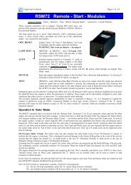
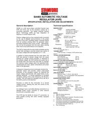
DSE Model 5220 Automatic Mains Failure & Instrumentation System Operators Manual8 INSTALLATION INSTRUCTIONSThe model DSE 5220 Module has been designed for front panel mounting. Fixing is by 4 clips for easy assembly.8.1 PANEL CUT-OUT160.00mm(6.3”)220.00mm(8.7”)FIG 3Maximum panel thickness – 8mm (0.3”)In conditions of excessive vibration the module should be mounted on suitable anti-vibration mountings.8.2 COOLINGThe module has been designed to operate over a wide temperature range -30 to +70º C. Allowances should bemade for the temperature rise within the control panel enclosure. Care should be taken NOT to mount possibleheat sources near the module unless adequate ventilation is provided. The relative humidity inside the controlpanel enclosure should not exceed 95%.8.3 UNIT DIMENSIONSPanel cutout 220mm x 160mm ( 8.7” x 6.3”)FIG 45220 OPERATING MANUAL ISSUE 5.1 18-Jun-07 AM 27
8.4 FRONT PANEL LAYOUTDSE Model 5220 Automatic Mains Failure & Instrumentation System Operators Manual8.5 REAR PANEL LAYOUTFIG 5FIG 628 057-012 5220 OPERATING MANUAL ISSUE 5.1 18/06/2007 AM
DSE Model 5220 Automatic Mains Failure & Instrumentation System Operators Manual9 ELECTRICAL CONNECTIONSConnections to the Module are via plug and sockets.9.1 CONNECTION DETAILSThe following describes the connections and recommended cable sizes to the 7 plugs and sockets on the rear ofthe Module. See rear panel layout FIG 6.9.1.1 PLUG “A” 8 WAYPIN DESCRIPTION CABLENOTESNoSIZE1 DC Plant Supply Input 2.5mm(negative)2 DC Plant Supply Input 2.5mm (Recommended Maximum Fuse 21A)(positive)3 Emergency Stop Input 2.5mm Plant Supply positive. Also supplies fuel & startoutputs.(Recommended Maximum Fuse 32A)4 Fuel relay Output 2.5mm Plant Supply positive from pin 3. 16 Amp rated.5 Start relay Output 2.5mm Plant Supply positive from pin 3. 16 Amp rated.6 Auxiliary Output relay 1 1.0mm Plant Supply positive. 5 Amp rated.7 Auxiliary Output relay 2 1.0mm Plant Supply positive. 5 Amp rated.8 Auxiliary Output relay 3 1.0mm Plant Supply positive. 5 Amp rated.9.1.2 PLUG “B” 11 WAYPIN DESCRIPTION CABLENOTESNoSIZE9 Charge fail / excite 2.5mm Do not connect to ground (battery –ve)10 Auxiliary input 1 0.5mm Switch to negative11 Auxiliary input 2 0.5mm Switch to negative12 Auxiliary input 3 0.5mm Switch to negative13 Auxiliary input 4 0.5mm Switch to negative14 Auxiliary input 5 0.5mm Switch to negative15 Auxiliary input 6 0.5mm Switch to negative16 Functional Earth 2.5mm Connect to a good clean earth point17 Magnetic pickup positive 0.5mm Connect to Magnetic Pickup device18 Magnetic pickup negative 0.5mm Connect to Magnetic Pickup device19 Not connected -NOTE:- Ensure magnetic pickup screen is connected to ground at one end only.9.1.3 PLUG “C” 3 WAY (NOT FITTED)5220 OPERATING MANUAL ISSUE 5.1 18-Jun-07 AM 29
DSE Model 5220 Automatic Mains Failure & Instrumentation System Operators Manual9.1.4 PLUG “D” 4 WAY (OPTIONAL)PIN DESCRIPTION CABLENOTESNoSIZE23 RS485 port Common 0.5mm Use only 120Ω RS485 approved cable24 RS485 port B 0.5mm Use only 120Ω RS485 approved cable25 RS485 port A 0.5mm Use only 120Ω RS485 approved cable26 Not connected -9.1.5 PLUG “E” 8 WAYPIN DESCRIPTION CABLE SIZE NOTESNo27 Mains loading relay 1.0mm Connect to mains contactor coil28 Mains loading relay 1.0mm Connect to mains contactor feed supply29 Generator loading relay 1.0mm Connect to generator contactor coil30 Generator loading relay 1.0mm Connect to generator contactor feed supply31 Mains (utility) L1 voltagemonitoring input1.0mm Connect to mains L1 (AC)(Recommend 2A fuse)32 Mains (utility) L2 voltagemonitoring input1.0mm Connect to mains L2 (AC)(Recommend 2A fuse)33 Mains (utility) L3 voltagemonitoring input1.0mm Connect to mains L3 (AC)(Recommend 2A fuse)34 Mains (utility)Neutral input 1.0mm Connect to mains Neutral (AC)9.1.6 PLUG “F” 4 WAYPIN DESCRIPTION CABLE SIZE NOTESNo35 Generator L1 voltagemonitoring input1.0mm Connect to generator L1 output (AC)(Recommend 2A fuse)36 Generator L2 voltagemonitoring input1.0mm Connect to generator L2 output (AC)(Recommend 2A fuse)37 Generator L3 voltagemonitoring input1.0mm Connect to generator L3 output (AC)(Recommend 2A fuse)38 Generator Neutral input 1.0mm Connect to generator Neutral terminal (AC)9.1.7 PLUG “G” 5 WAYPIN No DESCRIPTION CABLE SIZE NOTES39 CT Secondary for L1 2.5mm Connect to secondary of L1 monitoring CT40 CT Secondary for L2 2.5mm Connect to secondary of L2 monitoring CT41 CT Secondary for L3 2.5mm Connect to secondary of L3 monitoring CT42 CT secondary common 2.5mm Connect to secondary of all monitoring CT’s43 Not connected -30 057-012 5220 OPERATING MANUAL ISSUE 5.1 18/06/2007 AM
DSE Model 5220 Automatic Mains Failure & Instrumentation System Operators Manual9.1.8 PLUG “H” 4 WAYPIN DESCRIPTION CABLENOTESNoSIZE44 Oil Pressure Input 0.5mm Connect to Oil pressure sender45 Coolant Temperature 0.5mm Connect to Coolant Temperature senderInput46 Fuel Level input 0.5mm Connect to Fuel Level sender47 Sender Common Return 0.5mm Return feed for senders*.NOTE*:- If using single terminal senders refer to connection diagram. If using earth return typesenders connect return terminals to pin 47 and also connect pin 47 to earth. This is detailed in theAppendix section entitled “Sender wiring recommendations” elsewhere in this manual.5220 OPERATING MANUAL ISSUE 5.1 18-Jun-07 AM 31
DSE Model 5220 Automatic Mains Failure & Instrumentation System Operators Manual9.1.9 PC CONFIGURATION INTERFACE CONNECTOR8-way connector allows connection to PC via the 810 configuration interface.Module can then be re-configured utilising the 5200 series configurationsoftware.9.1.10 EXPANSION OUTPUT CONNECTORThe expansion connector allows connection to the 157 relay expansion moduleor to the 548 LED Remote annunciator module.32 057-012 5220 OPERATING MANUAL ISSUE 5.1 18/06/2007 AM
DSE Model 5220 Automatic Mains Failure & Instrumentation System Operators Manual9.2 CONNECTOR FUNCTION DETAILSThe following describes the functions of the 3 connectors on the rear of the module. See rear panel layout FIG 5.9.2.1 PLUG “A” 8 WAYPINDESCRIPTIONNo1 DC Supply negative. System DC negative input. (Battery Negative).2 DC Supply positive. System DC positive input. (Battery Positive).3 Emergency Stop input. Internally linked to Starter and Fuel outputs. If this input is notconnected to positive the module will be locked out, and if the engine is running it willshutdown immediately. The Positive Supply is also removed from Starter and Fuel outputs,therefore only a single pole Emergency Shutdown button is required.4 Fuel Relay output. Plant Supply positive from pin 3. Used to control the fuel solenoid orengine fuel control system.5 Starter Relay output. Plant Supply positive from pin 3. Used to control the Starter Motor.6 Auxiliary Relay output 1. Plant Supply positive. Configurable output, see Calibration Manualfor options available.7 Auxiliary Relay output 2. Plant Supply positive. Configurable output, see Calibration Manualfor options available.8 Auxiliary Relay output 3. Plant Supply positive. Configurable output, see Calibration Manualfor options available.9.2.2 PLUG “B” 11 WAYPINDESCRIPTIONNo9 Charge Fail input / Excitation output. Supplies excitation to the Plant Battery ChargingAlternator, also an input for the Charge Fail detection circuitry.10 Auxiliary input 1. This is a negative switched configurable input, see Calibration Manual foroptions available. It is possible to configure the input to be a normally closed signal or anormally open signal.11 Auxiliary input 2. This is a negative switched configurable input, see Calibration Manual foroptions available. It is possible to configure the input to be a normally closed signal or anormally open signal.12 Auxiliary input 3. This is a negative switched configurable input, see Calibration Manual foroptions available. It is possible to configure the input to be a normally closed signal or anormally open signal.13 Auxiliary input 4. This is a negative switched configurable input, see Calibration Manual foroptions available. It is possible to configure the input to be a normally closed signal or anormally open signal.14 Auxiliary input 5. This is a negative switched configurable input, see Calibration Manual foroptions available. It is possible to configure the input to be a normally closed signal or anormally open signal.15 Auxiliary input 6. This is a negative switched configurable input, see Calibration Manual foroptions available. It is possible to configure the input to be a normally closed signal or anormally open signal.16 Functional Earth - Ensure connection to a good clean earth point.17 Magnetic Input positive. An AC signal from the magnetic pickup positive for speed sensing.18 Magnetic Input negative. An AC signal from the magnetic pickup negative for speed sensing.19 Not connectedNOTE:- Ensure magnetic pickup screen is connected to ground at one end only.5220 OPERATING MANUAL ISSUE 5.1 18-Jun-07 AM 33
DSE Model 5220 Automatic Mains Failure & Instrumentation System Operators Manual9.2.3 PLUG “C” 3 WAY (NOT FITTED)9.2.4 PLUG “D” 4 WAY (OPTIONAL)PINDESCRIPTIONNo23 RS485 port Common24 RS485 port B. Use only screened 120Ω cable approved specifically for use in RS485 applications.25 RS485 port A. Use only screened 120Ω cable approved specifically for use in RS485 applications.26 Not used. Do not connect to this terminal.9.2.5 PLUG “E” 8 WAYPIN NoDESCRIPTION27 Mains loading relay, normally closed. Volts free contact to terminal 28.28 Mains loading relay, normally closed. Volts free contact to terminal 27.29 Generator loading relay, normally open. Volts free contact to terminal 30.30 Generator loading relay, normally open. Volts free contact to terminal 29.31 Mains L1 voltage monitoring input. Connect to mains L1 supply32 Mains L2 voltage monitoring input. Connect to mains L2 supply. If using single phase AC systemdo not connect to this terminal.33 Mains L3 voltage monitoring input. Connect to mains L3 supply. If using single phase or twophase AC system do not connect to this terminal.34 Mains Neutral input. Connect to mains N supply. If using 3phase 3wire AC system, do notconnect to this terminal.9.2.6 PLUG “F” 4 WAYPINDESCRIPTIONNo35 Generator L1 sensing input. Connect to alternator L1 output.36 Generator L2 sensing input. Connect to alternator L2 output. If using single phase only do notconnect this terminal.37 Generator L3 sensing input. Connect to alternator L3 output. If using single phase only do notconnect this terminal.38 Generator N sensing input. Connect to alternator N output.9.2.7 PLUG “G” 5 WAYPIN NoDESCRIPTION39 Generator L1 current transformer connection.40 Generator L2 current transformer connection. If single phase is used do not connect this pin.41 Generator L3 current transformer connection. If single phase is used do not connect this pin.42 Generator current transformer common connection and CT earth connection.43 Not used. Do not connect to this terminal.34 057-012 5220 OPERATING MANUAL ISSUE 5.1 18/06/2007 AM
DSE Model 5220 Automatic Mains Failure & Instrumentation System Operators Manual9.2.8 PLUG “H” 4 WAYPINDESCRIPTIONNo44 Oil Pressure sensing input. Connect to resistive type oil pressure sender. Refer to connectiondiagram for details.45 Coolant Temperature sensing input. Connect to resistive type coolant temperature sender. Referto connection diagram for details.46 Fuel Level sensing input. Connect to resistive type fuel level sender. Refer to connectiondiagram for details.47 Sender Common connection. Return feed from sender units - refer to connection diagram fordetails.9.2.9 PURCHASING ADDITIONAL CONNECTOR PLUGS FROM DSEIf you require additional plugs from DSE, please contact our Sales department using the part numbers below.5220 Terminal Connector Plug description DSE Part number1-8 A BL08 8way 5.08mm spacing connector plug 007-1259-19 B BL11 11way 5.08mm spacing connector plug 007-13520-22 C BL03 3way 3.81mm spacing connector plug 007-40923-26 D BL04 4way 3.81mm spacing connector plug 007-40827-34 E BL08 8way 10.16mm spacing connector plug 007-41035-38 F BL04 4way 10.16mm spacing connector plug 007-00339-43 G BL05 5way 5.08mm spacing connector plug 007-32944-47 H BL04 4way 5.08mm spacing connector plug 007-1005220 OPERATING MANUAL ISSUE 5.1 18-Jun-07 AM 35
DSE Model 5220 Automatic Mains Failure & Instrumentation System Operators Manual10 SPECIFICATIONDC Supply Continuous voltage rating :8V to 35VCranking dip protection :Able to survive 0V for 50mS, providing supply was at least 10V before dropout and supplyrecovers to 5V. This is achieved without the need for internal batteriesCharge Fail/ Excitation:0V to 35V fixed power source 25WMax. Standby Current:375mA at 12V. 200mA at 24V.Max. Operating Current:460mA at 12V. 245mA at 24VAlternator Input Range:5V - 277(ph-N) (+20%) 50Hz - 60Hz (Minimum 15V AC Ph-N)Accuracy:1% of full scale Average sensingSupported topologies:3 Phase 4wireSingle phase 2 wire3 phase 3 wire2 Phase 3 wire L1 & L22 Phase 3 wire L1 & L3Mains InputRange:15V - 277(ph-N) (+20%) 50Hz - 60HzAccuracy:1% of full scale Average sensingSupported topologies:3 Phase 4wireSingle phase 2 wire3 phase 3 wire2 Phase 3 wire L1 & L22 Phase 3 wire L1 & L3CT’sBurden:0.5VAPrimary rating:1A - 6000A (user selectable)Secondary rating:5A secondaryAccuracy of measurement:1% of full load rating (when using 0.5% or better CTs)Lower class CTs will reduce the overall accuracy of the reading.Recommendations:Class 1 required for instrumentationProtection class required if using for protection.Magnetic Pickup Voltage range :+/- 0.5V minimum (during cranking) to 70V PeakFrequency range:10,000 Hz (max)Relay outputs Fuel:16 Amp DC at supply voltageStart:16 Amp DC at supply voltageAuxiliary outputs 1,2,3:5 Amp DC at supply voltageDimensionsOverall:240mm x 172 mm x 57mm(9 ½“ x 6 ¾” x 2 ¼”)Panel cut-out:220mm x 160mm( 8.7” x 6.3”)Max panel thickness 8mm ( 0.3”)36 057-012 5220 OPERATING MANUAL ISSUE 5.1 18/06/2007 AM
DSE Model 5220 Automatic Mains Failure & Instrumentation System Operators ManualElectrical Safety/ElectromagneticCompatibilityEnvironmentalProduct CertificationBS EN 60950 Safety of information technology equipment, including electrical business equipmentBS EN 61000-6-2 EMC Generic Emission Standard (Industrial)BS EN 61000-6-4 EMC Generic Emission Standard (Industrial)BS EN 60068-2-1 Cold Temperature-30°CBS EN 60068-2-2 Hot Temperature+70°CBS2011-2-1 Humidity93% RH@40°C for 48 HoursBS EN 60068-2-6 Vibration10 sweeps at 1 octave/minute in each of 3 major axes5Hz to 8Hz @ +/-7.5mm constant displacement8Hz to 500Hz @ 2gn constant accelerationBS EN 60068-2-27 Shock3 Half sine shocks in each of 3 major axes15gn amplitude, 11mS durationBS EN 60529 Degrees of protection provided by enclosures:IP55 (Front of module when module is installed into the control panel with the optional sealinggasket).IP42 (front of module when module is installed into the control panel WITHOUT being sealed tothe panel)NEMA Rating (Approximate)12 (Front of module when module is installed into the control panel with the optional sealinggasket).2 (front of module when module is installed into the control panel WITHOUT being sealed to thepanel)CUSEuropean CE approved.UL approvedC-UL / CSA approved.Russia and other CIScountries approvedRelevant CompanyCertificationBS EN 2002/95/ECRestriction of HazardousSubstances(RoHS)BS EN 2002/96/ECWaste Electrical andElectronic Equipment (WEEE)BS EN ISO 9001:2000Applicable to Design,marketing, assembly, serviceand repair of electronic controlmodulesIn line with our policy of continual development, Deep Sea Electronics, reserve the right to change specification without notice.5220 OPERATING MANUAL ISSUE 5.1 18-Jun-07 AM 37
11 COMMISSIONINGDSE Model 5220 Automatic Mains Failure & Instrumentation System Operators Manual11.1.1 PRE-COMMISSIONINGBefore the system is started, it is recommended that the following checks are made:-7.1. The unit is adequately cooled and all the wiring to the module is of a standard and rating compatible with thesystem.7.2. The unit DC supply is fused and connected to the battery and that it is of the correct polarity.7.3. The Emergency Stop input is wired to an external normally closed switch connected to DC positive.NOTE:- If Emergency Stop feature is not required link this input to the DC Positive. The module willnot operate unless either the Emergency Stop is fitted correctly OR Pin 3 is connected to DC positive(positive)7.4. To check the start cycle operation take appropriate measures to prevent the engine from starting (disable theoperation of the fuel solenoid). After a visual inspection to ensure it is safe to proceed, connect the batterysupply. Select “MANUAL”, the unit start sequence will commence.7.5. The starter will engage and operate for the pre-set crank period. After the starter motor has attempted to startthe engine for the pre-set number of attempts the LCD will display its icon indicating; ‘Failed to start’ .Select the STOP/RESET position to reset the unit.7.6. Restore the engine to operational status (reconnect the fuel solenoid), again select “MANUAL”, this time theengine should start and the starter motor should disengage automatically. If not then check that the engine isfully operational (fuel available, etc.) and that the fuel solenoid is operating. The engine should now run up tooperating speed. If not, and an alarm is present, check the alarm condition for validity, then check inputwiring. The engine should continue to run for an indefinite period. It will be possible at this time to view theengine and alternator parameters - refer to the ‘Description of Controls’ section of this manual.7.7. Select “AUTO” on the front panel, the engine will run for the pre-set cooling down period, then stop. Thegenerator should stay in the standby mode. If not check that there is not a signal present on the Remotestart input and that the mains (utility) supply is healthy and available.7.8. Initiate an automatic start by supplying the remote start signal or failing the mains(utility) supply. The startsequence will commence and the engine will run up to operational speed. Once the generator is available aload transfer will take place, the Generator will accept the load. If not, check the wiring to the GeneratorContactor Coil (if used). Check the Warming timer has timed out.7.9. Remove the remote start signal and/or ensure the mains (utility) supply is healthy, the return sequence willstart. After the pre-set time period, the load will be removed from the generator. The generator will then runfor the pre-set cooling down period, then shutdown into it’s standby mode.7.10. Set the modules internal clock/calendar to ensure correct operation of the scheduler and event loggingfunctions. For details of this procedure see section entitled Front Panel Configuration – Editing the date/time.7.11. If despite repeated checking of the connections between the 5220 and the customer’s system, satisfactoryoperation cannot be achieved, then the customer is requested to contact the factory for further advice on:-INTERNATIONAL TEL: +44 (0) 1723 890099INTERNATIONAL FAX: +44 (0) 1723 893303E-mail: Support@Deepseaplc.comWebsite : www.deepseaplc.com38 057-012 5220 OPERATING MANUAL ISSUE 5.1 18/06/2007 AM
12 FAULT FINDINGDSE Model 5220 Automatic Mains Failure & Instrumentation System Operators ManualSYMPTOMUnit is inoperativeUnit shuts downUnit locks out on Emergency StopIntermittent Magnetic Pick-upsensor faultLow oil Pressure fault operatesafter engine has firedHigh engine temperature faultoperates after engine has fired.Shutdown fault operatesWarning fault operatesFail to Start is activated after presetnumber of attempts to startContinuous starting of generatorwhen in AUTOGenerator fails to start on receiptof Remote Start signal or mains(utility) supply failure.Pre-heat inoperativeStarter motor inoperativeEngine runs but generator will nottake loadIncorrect reading on EnginegaugesPOSSIBLE REMEDYCheck the battery and wiring to the unit. Check the DC supply. Check the DCfuse.Check DC supply voltage is not above 35 Volts or below 9 VoltsCheck the operating temperature is not above 70 °C. Check the DC fuse.If an Emergency Stop Switch is not fitted, ensure that a positive is connectedto the Emergency Stop input. Check emergency stop switch is functioningcorrectly. Check Wiring is not open circuit.Ensure that Magnetic pick-up screen is only connected at one end, ifconnected at both ends, this enables the screen to act as an aerial and willpick up random voltages.Check engine oil pressure. Check oil pressure switch/sender and wiring.Check configured polarity (if applicable) is correct (i.e. Normally Open orNormally Closed) or that sender is compatible with the 5220 Module and iscorrectly configured.Check engine temperature. Check switch/sender and wiring. Checkconfigured polarity (if applicable) is correct (i.e. Normally Open or NormallyClosed) or that sender is compatible with the 5220 Module.Check relevant switch and wiring of fault indicated on LCD display. Checkconfiguration of input.Check relevant switch and wiring of fault indicated on LCD display. Checkconfiguration of input.Check wiring of fuel solenoid. Check fuel. Check battery supply. Check batterysupply is present on the Fuel output of the module. Check the speed sensingsignal is present on the 5220 inputs. Refer to engine manual.Check that mains (utility) supply is healthy and check that it’s protection fusesare in place and are not blownCheck that there is no signal present on the “Remote Start” input. Checkconfigured polarity is correct.Check Start Delay timer has timed out.If remote start fault, check signal is on “Remote Start” input. Confirm input isconfigured to be used as “Remote Start”.Check wiring to engine heater plugs. Check battery supply. Check batterysupply is present on the Pre-heat output of module. Check pre-heat has beenselected in your configuration.Check wiring to starter solenoid. Check battery supply. Check battery supplyis present on the Starter output of module. Ensure that the Emergency Stopinput is at positive.Check Warm up timer has timed out. Ensure generator load inhibit signal isnot present on the module inputs.Check engine is operating correctly. Check sender and wiring payingparticular attention to the wiring to terminal 47 (refer to appendix). Check thatsender is compatible with the 5220 Module and is correctly configured.NOTE:- The above fault finding is provided as a guide check-list only. As it is possible for themodule to be configured to provide a wide range of different features always refer to the source of yourmodule configuration if in doubt.5220 OPERATING MANUAL ISSUE 5.1 18-Jun-07 AM 39
DSE Model 5220 Automatic Mains Failure & Instrumentation System Operators Manual13 FACTORY DEFAULT CONFIGURATIONIn the tables below, the icon indicates an item that can be adjusted from the module’s front panel editor.Absence of the icon beside an item means that adjustment of this parameter is only possible using the 5200series configuration software in conjunction with the P810 interface.For further details on adjustment from the front panel editor, see the section entitled “Front panel configuration”elsewhere within this manual.Module settingsBase moduleValue5220 automatic mains failure moduleMiscellaneous settings ValueAlternator fittedYesPoles 4Magnetic pickup fitted NoJ1939 enabledNoAC System3 phase, 4 wireVT RatioDisabledMains failure detection EnabledNumber of start attempts 3Enable fast loading feature NoImmediate mains dropout DisabledInput settings – Analogue | Oil pressureLow oil pressure input typeValueVDO 10 barTripReturnLow oil pressure pre-alarm 1.17 Bar 17.0 PSI 1.24 Bar 18.0 PSILow oil pressure shutdown 1.03 Bar 14.9 PSI N/AInput settings – Analogue | Coolant tempValueHigh coolant temp input typeVDO 120 degrees CHigh coolant temp pre-alarm 115°C 239°F 110°C 230°FHigh coolant temp shutdown 120°C 248°F N/AInput settings – Analogue | Fuel levelValueFuel level input typeVDO OhmRangeFuel pump controlNoLow fuel level 10%Input settings - Digital Value1 Remote start Close to activate2 Lamp test Close to activate3 User configured Close to activate, Warning Active from safety on4 User configured Close to activate, Shutdown Always active5 User configured Close to activate, Shutdown Active from safety on6 User configured Close to activate, Electrical trip Always active40 057-012 5220 OPERATING MANUAL ISSUE 5.1 18/06/2007 AM
DSE Model 5220 Automatic Mains Failure & Instrumentation System Operators ManualOutput settings – Relay Value1 Energise Preheat (during pre-heat timer)2 Energise Common alarm3 Energise System in auto mode4 Energise Close generator5 De-energise Close mainsOutput settings – Expansion A Value1 Energise Output not used2 Energise Output not used3 Energise Output not used4 Energise Output not used5 Energise Output not used6 Energise Output not used7 Energise Output not used8 Energise Output not usedLCD indicator settings Value1 Lit Digital input 1 active2 Lit Digital input 2 active3 Lit System in auto mode4 Lit Common alarmTimer settingsValueMains transient delay 1sStart delay 5sPre-heat 0sCranking time 10sCrank rest time 10sSmoke limit0sSmoke limit off0sSafety on delay 10sOverspeed overshoot 2sWarming up time 0sTransfer time 0.7sBreaker close pulse 0.5sBreaker trip pulse 0.5sReturn delay 30sCooling time 30sETS solenoid hold 0sFail to stop delay30sGenerator transient delay 1sBattery low volts delay1mBattery high volts delay1mLCD page timer5mMains (utility) settings – Voltage/frequency Trip ReturnUnder volts trip 180V AC 200V ACOver volts trip 280V AC 260V ACUnder frequency trip 45Hz 48HzOver frequency trip 52Hz 55Hz5220 OPERATING MANUAL ISSUE 5.1 18-Jun-07 AM 41
DSE Model 5220 Automatic Mains Failure & Instrumentation System Operators ManualGenerator settings – Voltage/frequency Trip ReturnUnder volts trip 184V AC N/AUnder volts pre-alarm 196V AC 207V ACOver volts pre-alarm 253V AC 265V ACOver volts trip 276V AC N/AUnder frequency trip 40.0 Hz N/AUnder frequency pre-alarm 42.0 Hz 45.0 HzOver frequency pre-alarm 55.0 Hz 52.0 HzOver frequency trip 57.0 Hz N/AGenerator settings – Current/power ValueGenerator CT primary600 AGenerator full load rating500 ADelayed overcurrent 100% ( 500 A )Trip Curve 36Engine settings – Crank disconnectCrank disconnect on generator frequencyCrank disconnect oil pressureCheck oil pressure prior to startingValue21.0 HzYesEngine settings – speed ValueUnderspeed trip 1250 RPMUnderspeed prealarm 1350 RPMOverspeed prealarm 1650 RPMOverspeed trip 1750 RPMOverspeed overshoot 0%Plant battery settings Trip ReturnUnder volts warning 8.0 V DC 9.0 V DCOver volts warning 33.0 V DC 32.0 V DCCharge alternator warning 8.0 V DC N/AExercise scheduler settingsEnable exercise schedulerValueNoCommsValueSite identityGenset IDModem modeNo modemModem init (not auto answer) +MS=11,1,,S7=60S0=0&S0&C1&D3Modem init (auto answer) +MS=11,1,,S7=60S0=2&S0&C1&D3Modem HangH0Master inactivity timeout 042 057-012 5220 OPERATING MANUAL ISSUE 5.1 18/06/2007 AM
DSE Model 5220 Automatic Mains Failure & Instrumentation System Operators Manual14 TYPICAL WIRING DIAGRAM5220 OPERATING MANUAL ISSUE 5.1 18-Jun-07 AM 43
DSE Model 5220 Automatic Mains Failure & Instrumentation System Operators Manual15 APPENDIX15.1 ALTERNATIVE WIRING TOPOLOGIESThe 5200 series controllers can support many different wiring topologies (AC systems) to suit the many systems inuse worldwide. The ‘Typical connection diagram’ details how to connect the module when used in a 3 phase, 4wire system (3 phase star connected alternators). Changes to this typical wiring diagram for other AC systems aredetailed below.NOTE:- The factory default configuration for the 5220 module is for use with the 3 phase, 4 wire ACsystem. If another system is to be used, the controller must be reconfigured using the 5200 seriesconfiguration software.15.1.1 3 PHASE, 3 WIREThe alternator is 3 phase delta connected. Phases are separated by 120°LOADGeneratorMechanical interlockMains (utility)L1L2CTEarthL1L2L3L3F2A F2A F2AGElectrical interlockMF2A F2A F2ACTcommon39 40 41 42 4335 36 37 29 30 38 34272831 32 33Not connectedGeneratorloadingrelayNot connectedNot connectedMainsloadingrelay15.1.2 1 PHASE, 2 WIRESingle phase alternator with neutral conductor.LOADMechanical interlockL1CTEarthL1GeneratorMains (utility)NF2A F2A F2AGElectrical interlockMF2ANCTcommon39 40 41 42 4335 36 37 382930272831 32 33 34Not connectedNot connectedNot connectedNot connectedNot connectedGeneratorloadingrelayMainsloadingrelayNot connectedNot connected44 057-012 5220 OPERATING MANUAL ISSUE 5.1 18/06/2007 AM
DSE Model 5220 Automatic Mains Failure & Instrumentation System Operators Manual15.1.3 2 PHASE, 3 WIRE ( 2 PHASE CENTRE TAP NEUTRAL)The alternator is 2 phase star connected. The live phases are separated by 180°LOADGeneratorMechanical interlockMains (utility)L1L2CTEarthL1L2NF2AF2AGElectrical interlockMF2AF2ANCTcommon39 40 41 42 4335 36 37 382930272831 32 33 34Not connectedGeneratorloadingrelayMainsloadingrelay5220 OPERATING MANUAL ISSUE 5.1 18-Jun-07 AM 45
DSE Model 5220 Automatic Mains Failure & Instrumentation System Operators Manual15.2 ICONS AND LCD IDENTIFICATION15.2.1 PUSH BUTTONSDisplay Description Display Description Display DescriptionStop/Reset Configure / log Auto modeScrollTest modeManual modeIStart (when inManual or Testmode)15.2.2 STATUS / MEASUREMENT UNITSDisplay Description Display Description Display DescriptionL1PhaseL2PhaseL3PhaseL1- N Phase - Neutral L2- N Phase - Neutral L3- N Phase -NeutralL1- L2 Phase - Phase L2- L3 Phase - Phase L3- L1 Phase - PhaseBAR Pressure KPaVAVoltageAmpereso Fo CKPa Oil PressureUnitskW KiloWatts kVA Apparent powerPSIPressureTemperature Hz FrequencyTemperature RPM SpeedKW divided bykVAHours Run AC GeneratorTimer in progress DC Mains (Utility)Configurationmode activePanel locked byconfigurable input15.2.3 ALARM INDICATIONSFuel levelEvent logDisplay Description Display Description Display DescriptionVVWarning Alarm Shutdown Alarm Electrical TripHigh CurrentFuel Low Oil PressureAWarningHigh CoolantCharge FailTemperature V Over Voltage (AC)Emergency StopFail to start (Overcrank)VUnder Voltage(AC)Over Voltage (DC) Over-speed Over frequencyUnder Voltage(DC)AuxiliaryIndication !Under-speedAuxiliary Alarm(Warning or Shutdown)Under frequency46 057-012 5220 OPERATING MANUAL ISSUE 5.1 18/06/2007 AM
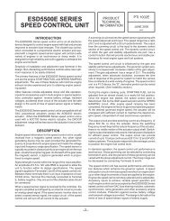
DSE Model 5220 Automatic Mains Failure & Instrumentation System Operators Manual15.3 5220 IDMT TRIPPING CURVES (TYPICAL)5220 Delayed over-current protection1000000100000Tripping time in seconds1000010001001011 2 3Current as a multiple of the trip-point setting (tripping curve = 36)5220 OPERATING MANUAL ISSUE 5.1 18-Jun-07 AM 47
DSE Model 5220 Automatic Mains Failure & Instrumentation System Operators Manual15.4 SENDER WIRING RECOMMENDATIONS15.4.1 EARTH RETURN SENDERSConnection NameTerminal NumberOil pressure Sender 44Coolant temperaturesender45Fuel level sender 46Sender common 47NOTE:- . It is important that terminal 47 ( sender common ) is soundly connected to an earth pointon the ENGINE BLOCK, not within the control panel, and must be a sound electrical connection to thesender bodies.NOTE:- . If you use PTFE insulating tape on the sender thread when using earth return senders,ensure you do not insulate the entire thread as this will prevent the sender body from being earthed viathe engine block.15.4.2 INSULATED RETURN SENDERSConnection NameTerminal NumberOil pressure Sender 44Coolant temperaturesender45Fuel level sender 46Sender common 47NOTE:- . It is important that terminal 47 ( sender common ) is soundly connected to an earth pointon the ENGINE BLOCK, not within the control panel .48 057-012 5220 OPERATING MANUAL ISSUE 5.1 18/06/2007 AM
15.4.3 FUEL LEVEL SENDERSDSE Model 5220 Automatic Mains Failure & Instrumentation System Operators ManualThe resistive fuel level senders supported by the 5200 series controllers are devices that translate fuel level intoresistance. A change in fuel level translates directly to a change in the resistance of the sender. In the case of aparallel sided fuel tank, an accurate measure of the fuel level can easily be made, however as shown in theexample below, this is not the case with non-parallel sided fuel tanks. Therefore it is recommended that onlyparallel sided fuel tanks are used to ensure correct fuel level detection.The fuel sender measuresthe distance between the topof the tank and the fuel level.Typically, they use a ballfloat.In this example, the distancebetween the top of the tankand the level of the fuel is50% of the height of thetank. The fuel level senderwill report the tank correctlyas being 50% full.For a parallel-sided tank likethis one, 50% distancebetween the top of the tankand the level of the fuel willoccur when the tank is 50%full of fuel.In this example, the distancebetween the top of the tankand the level of the fuel isagain 50% of the height ofthe tank, the fuel levelsender will report the tank asbeing 50% full.However, as the bottom ofthe tank is curved, the actualamount of fuel in the tank isonly about 40%. The fuelsender is incorrectlyreporting the amount ofremaining fuel.5220 OPERATING MANUAL ISSUE 5.1 18-Jun-07 AM 49
DSE Model 5220 Automatic Mains Failure & Instrumentation System Operators Manual15.5 5200 SERIES CONFIGURATION SOFTWARE AND P810 INTERFACE MODULEThe 5210 module can be configured using PC with Interface Module 810 and 52xx series PC configurationsoftware.The 5200 series configuration software kit comprises the following:-• 810 Interface Module• 25 to 9 way adapter• RJ45 (8 Pin) Connecting Lead• DSE SoftwareCD with configuration software15.6 OUTPUT EXPANSIONThere are several methods of output expansion available for the 5210 module:-15.6.1 RELAY OUTPUT EXPANSION (157)An expansion module is available, which connects to the configuration socket, andenables the 5210 to use eight additional relays, providing Volt-free contacts forcustomer connection.Refer to technical data sheet on the 157 relay module for further details.15.6.2 LED OUTPUT EXPANSION (548)An expansion module is available, which connects to the configuration socket, andenables the 5210 to use eight additional LED’s, providing remote LED indication upto 50 metres away.Refer to technical data sheet on the 548 LED module for further details.It is possible to use a mix of 157 and 548 modules to give both relay and LEDexpansion of the same 8 items if required (Please refer to our Technical Supportdepartment for details.).15.7 INPUT EXPANSIONIt is possible to increase the number of monitored inputs available by utilising aDSE 540/541 Protection Expansion/Annunciator. Please refer to our Technicaldepartment for details.15.8 STANDBY GENERATING SET?The 5210 needs to be given a remote start signal to initiate an engine start. This canbe supplied by a Mains/Utility monitoring module to make the generating set start upautomatically should the mains/utility supply fail. The 5210 module may be used inconjunction with DSE Automatic transfer switch controllers such as the model 500(pictured) , 705 or 530. These not only monitor the mains and issue a startcommand to the 5210; they also provide control of the contactors or otherchangeover devices. Please refer to our Technical Support department for details.50 057-012 5220 OPERATING MANUAL ISSUE 5.1 18/06/2007 AM
DSE Model 5220 Automatic Mains Failure & Instrumentation System Operators Manual15.9 ENCLOSURE CLASSIFICATIONSIP CLASSIFICATIONSBS EN 60529 Degrees of protection provided by enclosuresFirst DigitProtection against contact and ingress of solid objectsSecond digitProtection against ingress of water0 No protection 0 No protection1 Protected against ingress solid objects with adiameter of more than 50 mm. No protection againstdeliberate access, e.g. with a hand, but largesurfaces of the body are prevented from approach.2 Protected against penetration by solid objects with adiameter of more than 12 mm. Fingers or similarobjects prevented from approach.3 Protected against ingress of solid objects with adiameter of more than 2.5 mm. Tools, wires etc. witha thickness of more than 2.5 mm are prevented fromapproach.4 Protected against ingress of solid objects with adiameter of more than 1 mm. Tools, wires etc. with athickness of more than 1 mm are prevented fromapproach.5 Protected against harmful dust deposits. Ingress ofdust is not totally prevented but the dust must notenter in sufficient quantity to interface withsatisfactory operation of the equipment. Completeprotection against contact.6 Protection against ingress of dust (dust tight).Complete protection against contact.1 Protection against dripping water falling vertically. Noharmful effect must be produced (vertically fallingdrops).2 Protection against dripping water falling vertically.There must be no harmful effect when the equipment(enclosure) is tilted at an angle up to 15° from itsnormal position (drops falling at an angle).3 Protection against water falling at any angle up to 60°from the vertical. There must be no harmful effect(spray water).4 Protection against water splashed against theequipment (enclosure) from any direction. There mustbe no harmful effect (splashing water).5 Protection against water projected from a nozzleagainst the equipment (enclosure) from any direction.There must be no harmful effect (water jet).6 Protection against heavy seas or powerful water jets.Water must not enter the equipment (enclosure) inharmful quantities (splashing over).5220 OPERATING MANUAL ISSUE 5.1 18-Jun-07 AM 51
NEMA CLASSIFICATIONSDSE Model 5220 Automatic Mains Failure & Instrumentation System Operators ManualNOTE: - There is no direct equivalence between IP / NEMA ratings. IP figures shown areapproximate only.1Provides a degree of protection against contact with the enclosure equipment and against a limited amount of falling dirt.IP302Provides a degree of protection against limited amounts of falling water and dirt.IP313Provides a degree of protection against windblown dust, rain and sleet; undamaged by the formation of ice on the enclosure.IP643RProvides a degree of protection against rain and sleet:; undamaged by the formation of ice on the enclosure.IP324 (X)IP6612/12KProvides a degree of protection against splashing water, windblown dust and rain, hose directed water; undamaged by theformation of ice on the enclosure. (Resist corrosion).Provides a degree of protection against dust, falling dirt and dripping non corrosive liquids.IP6513Provides a degree of protection against dust and spraying of water, oil and non corrosive coolants.IP6552 057-012 5220 OPERATING MANUAL ISSUE 5.1 18/06/2007 AM
DSE Model 5220 Automatic Mains Failure & Instrumentation System Operators Manual>5220 OPERATING MANUAL ISSUE 5.1 18-Jun-07 AM 53