Nova DVR 3000 Manual_22 November 2002 - Teknatool
Nova DVR 3000 Manual_22 November 2002 - Teknatool
Nova DVR 3000 Manual_22 November 2002 - Teknatool

Create successful ePaper yourself
Turn your PDF publications into a flip-book with our unique Google optimized e-Paper software.
NOVA<strong>DVR</strong> <strong>3000</strong> TMWOODLATHEINSTRUCTION MANUALPublication No.101-0505-002Last updated 12 August 02Models55016 spindle thread 1 1/4" x 8 tpi 115v55078 spindle thread 1 1/4" x 8 tpi <strong>22</strong>0-240v101-0505-002 1
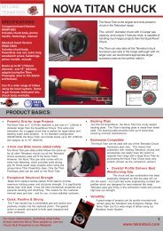
<strong>Nova</strong> <strong>DVR</strong> <strong>3000</strong> Lathe Features at a glance<strong>DVR</strong> Electronic driveThe <strong>Nova</strong> <strong>DVR</strong> lathe is unique. The <strong>DVR</strong> incorporates the motor built as part of theheadstock, the spindle and motor are one unit. The motor is maintenance free anddesigned with high reliability. The Digital variable reluctance motor uses smartmotor technology to provide an incredibly smooth and powerful drive. The drivetakes turning to a new level. The controller monitors the spindle position constantlyand maintains spindle speed very closely. Extra power is added as it senses extraload from the tool.Add on Bed SystemA lathe that meets your woodturning needs, your workshop space, or your pocket! Each segment is 20" in length.The feature appeals for many different reasons:As a compact lathe (standard configuration) it is great for small turning workshopspaces.As an extended lathe for those wanting to do extra long spindles (beyond thetraditional between center of most lathes) the <strong>Nova</strong> <strong>3000</strong> delivers big turningcapacity. Illustrated at left.As a bowl lathe for those just wanting to turn bowls.Sophisticated Swivel HeadSwivel head lathes have many advantages:• Space saving• Allows the turner (not the machine!) to decide the most comfortable position for yourturning (saving you from backstrain)• Elimination of left-hand ‘outboard’ turning techniques and no extra outboard chucks and faceplates arenecessary.There are a number of swivel head lathes available, but the <strong>Nova</strong> <strong>3000</strong> has by far the most sophisticated, accurateand easy to use swivel head on the market.The <strong>Nova</strong> <strong>3000</strong> lathe can be easily and quickly swiveled to any position (360 degrees). It can be solidly locked inany position plus it has the added security of a detent pin lock at 0,<strong>22</strong>.5,45,90 plus 315 (for left-hand use).The swivel head turns, locks easily and has a very accurate detent position, to lock the spindle in line with thetailstock. Then for super accuracy the adjustable tailstock can be finely tuned for pin point alignment (this isfactory set but can be adjusted in the field). This combination of detent pin and adjustable tailstock, delivers superbaccuracy and is unique to the <strong>Nova</strong> <strong>3000</strong>.Solid ConstructionWell proven design, the <strong>Nova</strong> <strong>3000</strong> is made from Cast Iron components for strength and rigidity. Added featureslike the heavy duty twin bearing system, and special webbed bed design makes the lathe well equipped to takeheavy turning stresses. The bed has been designed with vibration dampening qualities - a solid 1/2" cross rib ispositioned long the bed unit, quickly dissipating any vibration as it travels down the bed.Cast-iron has always been the material of choice for Woodlathe construction its inherent mass and an excellentmodulus of vibration2 101-0505-002
101-0505-002 3
WelcomeThank you for choosing our <strong>Nova</strong> <strong>DVR</strong> <strong>3000</strong> Woodlathe and welcome to the <strong>Teknatool</strong> productfamily. Your choice shows you want the best for your woodturning and you recognise the superb<strong>DVR</strong> drive technology and the host of other unique features the <strong>Nova</strong> <strong>DVR</strong> <strong>3000</strong> offers.We strive to achieve the best value for your money – providing quality, innovative features, a widerange of accessories (some like our Ornamental Turner are unique to <strong>Teknatool</strong>) – pluscomprehensive, ongoing support (latest manuals downloadable from our website, newsletters,projects etc). We are only a phone call or email away with technical advice or assistance on theoperation of your lathe or your woodturning queries.Please feel free to contact us about any aspect of our products or service – we regard ourcustomers as our best development and improvement team – we would love to hear from you!Once again, welcome to the “<strong>Teknatool</strong> Family”. We trust that you enjoy our products and hopethey enhance the pleasure you experience from the wonderful craft of woodturning!Best RegardsBrian LatimerMarketing Director<strong>Teknatool</strong> International Ltd4 101-0505-002
Contact <strong>Teknatool</strong>?<strong>Teknatool</strong> International LtdP.O.Box 180034 Luckens PointHenderson, Auckland 1008New Zealand?Phone: (+64) 9 837 6900?Fax: (+64) 9 837 6901Email: service@teknatool.comWebsite: www.teknatool.comUnited States<strong>Teknatool</strong> InternationalFree Phone: 1-866-748-3025Free Fax: 1-866-748-4193Email: service@teknatool.comWebsite: www.teknatool.comWoodcraft Supply CorpTechnical Service: 1-800-535-4486Orders: 1-800-<strong>22</strong>5-1153Website: www.woodcraft.comContact them for a copy of their catalogue, or for a listof their stores throughout the USA.Australia<strong>Teknatool</strong> InternationalFree Phone: 1-800-140-761Free Fax: 1-800-140-755Email: service@teknatool.comWebsite: www.teknatool.comContact us for a free catalogue and a list of storesthroughout Australia.CanadaKMS Tools and Equipment LtdPhone: (+1) 604-5<strong>22</strong>-5599Free Phone: 1-800-567-8979Fax: (+1) 604-5<strong>22</strong>-0638Email: kmstools@kmstools.comWebsite: www.kmstools.comUnited KingdomRobert SorbyPhone: (+44) 114 <strong>22</strong>5 0700Fax: (+44) 114 <strong>22</strong>5 0710Email: sales@robert-sorby.co.ukWebsite: www.robert-sorby.co.ukFrancePhilbois Machines & Outils Pour Le BoisPhone: (+33) 4-94-68- 82-32Fax: (+33) 4-94-68-81-89Email: philbois@wanadoo.frIcelandGylfi SigurlinnasonPhone: (+354) 555-1212Fax: (+354) 555-2652Email: haki@centrum.isNorwayWWW VERKTOY ASPhone: (+47) 51-88-6800Fax: (+47) 51-88-6810Email: tredreie@ogreid.noWebsite: www.verktoyas.noJapanIkeda IncPhone: (+81) 555-726-860Fax: (+81) 555-726-865Email: fine@ikedatools.co.jpSouth AfricaThe Hardware CentrePhone: (27) 011 791 0844Fax: (27) 011 791 0850This is the list of Countries/Resellers that currentlystock and sell the <strong>Nova</strong> <strong>3000</strong> Woodlathe. In addition,<strong>Teknatool</strong> sells a more limited range into many othercountries. Contact us for details, or see our website.101-0505-002 5
Table of ContentsGeneral Safety Rules....................................................................................................... 6Additional Safety Rules for Woodlathes .......................................................................... 7<strong>Nova</strong> <strong>DVR</strong> <strong>3000</strong> Specifications........................................................................................ 8Setting Up Your Workshop .............................................................................................. 9Workshop Requirements........................................................................................... 9Lathe Stand Recommendations................................................................................ 9Assembling the <strong>Nova</strong> <strong>DVR</strong><strong>3000</strong> ...................................................................................... 11Adding an Extension Bed................................................................................................. 12Mounting the Lathe to a Support Surface.................................................................. 13Connecting to Power ................................................................................................. 13Using the <strong>Nova</strong> <strong>DVR</strong><strong>3000</strong>................................................................................................ 14<strong>DVR</strong> drive keypad functions ...................................................................................... 15Swiveling the Headstock............................................................................................ 17Spindle Index.............................................................................................................. 17Headstock.................................................................................................................. 18Toolrest...................................................................................................................... 19Tailstock..................................................................................................................... 21Learning Turning........................................................................................................ 21Maintaining the <strong>Nova</strong> <strong>DVR</strong><strong>3000</strong> ....................................................................................... <strong>22</strong>General Maintenance....................................................................................................... <strong>22</strong>Cleaning the Toolslide................................................................................................ <strong>22</strong>Cleaning the Tailstock................................................................................................ 23Troubleshooting Guide..................................................................................................... 23<strong>Nova</strong> <strong>DVR</strong><strong>3000</strong> Parts List................................................................................................ 26Accessories ..................................................................................................................... 29Index................................................................................................................................. 31Warranty .......................................................................................................................... 32© Copyright 2001 by <strong>Teknatool</strong> International; All Rights Reserved.<strong>Nova</strong> <strong>DVR</strong> <strong>3000</strong> is a trademark of <strong>Teknatool</strong> International Ltd.The information and specifications contained herein are subject to change. <strong>Teknatool</strong> is notresponsible for errors or omissions herein or for incidental damages in connection with thefurnishing or use of this information.6 101-0505-002
GENERAL SAFETY RULES! Warning! Failure to follow these rules may result in serious personalinjury.1. FOR YOUR OWN SAFETY, READ THE MANUALBEFORE OPERATING THE TOOL. Learn themachine’s application and limitations plus thespecific hazards peculiar to it.2. ALWAYS USE SAFETY GLASSES – FULLFACEMASK strongly recommended. Safetyglasses (must comply with ANSI STANDARDZ87.1 -USA) Everyday eye-glasses usually areonly impact resistant; they are not safety glasses.Also use face or dust mask if cutting operation isdusty.3. WEAR PROPER APPAREL. Do not wear looseclothing, gloves, neckties, rings, bracelets or otherjewelry which may get caught in moving parts.Non slip footwear is recommended. Wearprotective hair covering to contain long hair.4. USE EAR PROTECTORS. Use ear muffs forextended period of operation. Use muffs rated to103 DBA LEQ (8 hour).5. DON’T USE IN DANGEROUS ENVIRONMENT. Don’tuse power tools in damp or wet locations, orexpose them to rain. Keep work area well lighted.6. KEEP WORK AREA CLEAN. Cluttered areas andbenches invite accidents. Build up of sawdust is afire hazard.7. KEEP CHILDREN AND VISITORS AWAY. Allchildren, infirm and visitors should be kept a safedistance from work area.8. MAKE WORKSHOP CHILDPROOF with locks,master switches, or by removing starter keys.9. GROUND ALL TOOLS. If the tool is equipped witha three prong plug, it should be plugged into athree hole electrical receptacle. If an adapter isused to accommodate a two prong receptacle, theadapter lug must be attached to a known ground.Never remove the third prong.10. MAKE SURE TOOL IS DISCONNECTED FROMPOWER SUPPLY while the motor is beingmounted, connected, or reconnected.11. DISCONNECT TOOLS from wall socket beforeservicing and when changing accessories suchas blades, bits cutters and fuses etc.12. AVOID ACCIDENTAL STARTING. Make sureswitch is in the Off position before plugging inpower cord.13. NEVER LEAVE MACHINE RUNNINGUNATTENDED. Do not leave tool unless it is turnedoff and has come to a complete stop.14. KEEP GUARDS IN PLACE and in working order.15. USE RIGHT TOOL. Do not use a tool orattachment to do a job for which it was notdesigned.16. USE RECOMMENDED ACCESSORIES. The use ofimproper accessories may cause hazards.17. DON’T FORCE TOOL. It will do the job better andbe safer at the rate for which it was designed.18. MAINTAIN TOOLS IN TOP CONDITION. Keeptools sharp and clean for best and safestperformance. Follow instructions for lubricatingand changing accessories.19. NEVER STAND ON TOOL. Serious injury couldoccur if the tool is tipped or if the cutting tool isaccidentally contacted.20. REMOVE ADJUSTING KEYS AND WRENCHES.Form a habit of checking to see that keys andadjusting wrenches are removed from tool beforeturning it on.21. DON’T OVERREACH. Keep proper footing andbalance at all times.<strong>22</strong>. DIRECTION OF FEED. Feed work into a blade orcutter against the direction of rotation of the bladeor cutter only.23. ATTENTION TO WORK. Concentrate on yourwork. If you become tired or frustrated, leave it forawhile and rest.24. SECURE WORK. Use clamps or a vice to hold workwhen practical. It’s safer than using your hand andfrees both hands to operate tool.25. CHECK DAMAGED PARTS. Before further use ofthe tool, any part that is damaged should becarefully checked to ensure that it will operateproperly and perform its intended function. Checkfor alignment of moving parts, binding of movingparts, mounting, and any other conditions that mayaffect its operation. Any damaged part should beproperly repaired or replaced.26. DRUGS, ALCOHOL, MEDICATION. Do not operatetool while under the influence of drugs, alcohol, orany medication.27. DUST WARNING. The dust generated by certainwoods and wood products can be harmful to yourhealth. Always operate machinery in wellventilated areas and provide for proper dustremoval. Use wood dust collection systemswhenever possible.101-0505-002 7
ADDITIONAL SAFETY RULES FOR WOODLATHES! Warning! Failure to follow these rules may result in serious personalinjury. Important ALWAYS BEFORE SWITCHING SPINDLE ON,CHECK SCREEN FOR CORRECT SETTING1. DO NOT MODIFY OR USE LATHE FOR USESOTHER THAN FOR WHICH IT WAS DESIGNED.2. SEEK INSTRUCTION. If you are not thoroughlyfamiliar with the operation of woodlathes, obtainadvice from your supervisor, instructor, or otherqualified person. Instruction from a qualifiedperson is strongly recommended.3. DO NOT OPERATE LATHE until it is completelyassembled and installed follow instructions andrecommendations.4. FOLLOW ELECTRICAL CODES. Make surewiring codes and recommended electricalconnections are followed and that the machine isproperly grounded.5. <strong>DVR</strong> <strong>3000</strong> Do not open the switch and rearcovers. Components can carry dangerousvoltages even when isolated from mains power.6. <strong>DVR</strong> <strong>3000</strong> Always ensure spindle fixtures(e.g. faceplates etc) are locked to spindle incase spindle reverse is engaged. Otherwisethey will unwind from spindle.7. WHEN SPINDLE REVERSE IS ENGAGED DO NOTUSE CHISELS OR CUTTING TOOLS USE FORSANDING ONLY8. KEEP WORK AREA CLEAN. Do not turn the latheOn before clearing the lathe of all objects (tools,scraps of wood, etc.). Keep the nearby area andfloor clear of debris.9. CHECK SET-UP with spindle Off. Examine the setupcarefully and rotate the work piece by hand tocheck clearance and check speed is correctlyselected before turning on spindle.10. DO NOT MAKE ADJUSTMENTS when the lathe orwork piece is turning. Make all adjustments withpower Off.11. TIGHTEN ALL CLAMP HANDLES on theheadstock, tailstock, and toolrest before operatinglathe.12. EXAMINE WORK PIECE and glue joints beforeturning to make sure it has no defects that wouldcause it to break when turning.13. <strong>DVR</strong><strong>3000</strong> ALWAYS CHECK CORRECT SPEED ISSELECTED BEFORE SWITCHING ON SPINDLE14. USE LOWEST SPEED when turning a new orunbalanced work piece.15. TURN AT RECOMMENDED SPEED. Alwaysoperate the lathe at the recommended speeds.Consult this manual for suggested speeds.16. ADJUST TOOLREST close to the work piece.Before turning, revolve the stock by hand to makesure it clears the rest. At intervals, stop the latheand readjust the toolrest.17. KEEP TOOL ON TOOLREST. The lathe tool orchisel should be on the toolrest before the lathe isturned On. Tools should remain on the toolrestwhenever the tool is engaged in contact with thework piece.18. REMOVE TOOLREST when sanding or polishingso fingers do not get pinched.19. USE CORRECT LATHE TOOLS. Do not use spindleturning chisels for faceplace mounted work, and viceversa. Spindle turning tools used for faceplatemounted work may grab the work piece and pull thechisel from your control.20. WHEN ROUGHING STOCK do not jam the lathe tool orchisel into work piece or take too big a cut.21. DO NOT POUND WORK PIECE into headstock drive(spur) center when turning between centers. Poundthe drive center into the work piece with a soft malletbefore installing it between centers in the lathe.<strong>22</strong>. DO NOT USE TAILSTOCK to drive work piece intothe drive (spur) center when turning betweencenters. Secure work between centers with lightpressure from the tailstock quill action.23. FASTEN STOCK SECURELY BETWEEN CENTERS.Make sure the tailstock is locked before turning onthe power.24. NEVER LOOSEN TAILSTOCK spindle or tailstockwhile work piece is turning.25. CORRECTLY USE FACEPLATE. When faceplateturning, make sure work piece is securely fastenedto the faceplate and that appropriate size faceplate isused to support the work piece. Any screwfasteners must not interfere with the turning tool atthe finished dimension of the work piece. Rough-cutthe work piece as close as possible to finishedshape before installing on faceplate.26. DO NOT OPERATE LATHE IF DAMAGED ORFAULTY. If any part of your lathe is missing,damaged or broken, in any way, or any electricalcomponent fails, shut off the lathe and disconnectthe lathe from the power supply. Replace missing,damaged, or failed parts before resuming operation.27. ADDITIONAL SAFETY INFORMATION regarding thesafe and proper operation of this product is availablefrom the National Safety Council, 444 N. MichiganAvenue, Chicago, IL 60611 in the AccidentPrevention <strong>Manual</strong> of Industrial Operations and alsoin the Safety Data Sheets provided by the NSC. Alsorefer to the American National Standards InstituteANSI 01.1 Safety Requirements for WoodworkingMachines and the U.S Department of Labor OSHA1910.213 Regulation.Guidelines to symbols used in this manual:!Warning Symbol. Pay close attention!? Note/Information Symbol. Please read - importantinformation for you.8 101-0505-002
<strong>DVR</strong> <strong>3000</strong> Woodlathe SpecificationsSize: see drawing below.Weight: 82 kg (181 LB)Swing Over Bed: 400 mm (16 in.)Distance Between Centers: 600 mm (24 in.);expandable in 510 mm (20 in.) units withadd-on Bed sections.Swing Outboard: 740 mm (29 in.) with headstockat 90° using outrigger toolrest.Headstock:Spindle Thread: M33 x 3.5 RH (1) or1-1/4 x 8 TPI RH (2)Headstock Bore: No. 2 Morse Taper (#2 MT)Headstock Swivel: 0 to 360 degrees, withdetents at 0, <strong>22</strong>.5, 45, and 90 degrees.Outboard End Internal Thread: M20 x 1.5 LHSpindle Index: 24 divisions (every 15 degrees)Tailstock:Tailstock Bore: No. 2 Morse Taper (#2 MT)Quill Travel: 85 mm (3-1/4 in.)Hole Through Tailstock: 15 mm (9/16 in.)Toolrest:Length: 300 mm (12 in.)Shaft Diameter: 25.4 mm (1 in.)Speeds (rpm):250 – 3500 (in 10rpm increments)Standard Equipment:300 mm (12 in.) Toolrest, 80mm (3 in.) Faceplate(Not all countries, see notes below), (Not allcountries, see notes below) Spur Center, andLive Center.<strong>Nova</strong> <strong>3000</strong> Bowl Lathe Version:Specifically for bowl turning, does not include bedextension, tailstock, and centers.Optional Accessories:<strong>Nova</strong> Chuck SystemSuper<strong>Nova</strong> Chuck SystemFaceplates: 80 mm (3 in.), 150 mm (6 in.)Vacuum FaceplateToolrest: 100 mm (4 in.)Bowl ToolrestOutrigger Toolrest UnitHandwheelVacuum CouplerRevolving Center SystemOrnamental TurnerNotes:(1) Applicable to UK, Europe,(2) Applicable to United States, Canada, Australia,New Zealand & South Africa.? Note: Standard equipment varies from country tocountry. In the USA, the 80mm 3" faceplate is includedwith the lathe as standard equipment. In other markets,the faceplate is optional equipment. Check with yourreseller if you are unsure.101-0505-002 9
Setting Up Your WorkshopWorkshop RequirementsConsiderationLatheLocationLightingElectricalVentilationRecommendationLocate the <strong>Nova</strong> <strong>DVR</strong> <strong>3000</strong> close to a power source in an area withgood lighting. Leave enough clearance on all sides of the lathe; allowfor motor clearance when the headstock is swiveled. Other machinesin your shop should not interfere with the operation of the lathe.Your shop should have adequate lighting. The work area of the latheshould be well lit; there should not be shadows cast on your work. Ifpossible, locate near a window. A movable spotlight may be helpful.The <strong>Nova</strong> <strong>DVR</strong> <strong>3000</strong> requires the appropriate outlet nearby to powerthe motor. Wiring and outlets should adhere to local electrical codes.If in doubt, seek advice from an electrician. Minimize use ofextension cords.Your shop should be adequately ventilated. The degree of ventilationwill vary based on the size of the shop and the amount of work done.The use of dust collectors and filters will minimize risks to yourhealth.Lathe Stand RecommendationsA sturdy and rigid stand is required so that the <strong>Nova</strong> <strong>DVR</strong> <strong>3000</strong> Woodlathe can deliver optimumperformance. A common flaw with many woodlathe installations is an inadequate stand for thelathe. The larger the size of your turnings, the greater the importance of the lathe stand design.ConsiderationLathe Heightfrom floorStand TopStand WeightStand LegsRecommendationThe height of the stand should locate the centerline of the lathespindle at the elbow height of the turner.( illustration next page)The stand top should be flat so the lathe does not twist when it isbolted down. Check for any gaps between lathe feet and standtop before bolting down. Shim and prepare stand as necessary..The stand should have enough weight and mass so it doesn'tmove when turning large work pieces, and so that the stand canabsorb vibrations. A lathe stand's stability can be improved byweighing it down with sand bags on a lower shelf.The stand should sit level on the floor and not rock.10 101-0505-002
Example of Shop-made Lathe StandTop43 x 16 x 2 in.Upper Leg Brace (2)1-1/2 x 3-1/2 x 13 in.MachineBolt (12)Upper Rail (2)1-1/2 x 3-1/2 x 33 in.plywood bottom(compartment for sand)Leg (4)1-1/2 x 3-1/2 in. xheight to suit turnerLower Leg Brace (2)1-1/2 x 7-1/2 x 13 in.Glue and screw leg piecesLower Rail (2)1-1/2 x 7-1/2 x 33 in.Recessed Hole,drill hole and chisel oneside square for nut.297 mm(11-11/16 in.)to suitturner101-0505-002 11
Assembling the <strong>Nova</strong> <strong>DVR</strong> <strong>3000</strong>1. Unpack the lathe and components from the shipping container. This is best done bycutting down the sides of the box to expose the lathe! Warning!Have other people help when moving or lifting the <strong>Nova</strong> <strong>DVR</strong> <strong>3000</strong>Woodlathe; it weighs about 82 kg (181 LB).2. Clean any parts coated with rust preventative with a cloth moistened with a petroleumbasedsolvent or cleanser, such as paint thinner. Coat the lathe bed with paste wax.<strong>Nova</strong> <strong>DVR</strong> <strong>3000</strong> Components After UnpackingSpindle<strong>DVR</strong>ControllerTailstockBedToolrest, headstock swivel pin,(faceplate optional), operatingbars, extraction nut, centers,operating bar.3. Remove the plastic shipping tubingfrom headstock base. Screw theHeadstock Lockpin into the threadedhole at the bottom of the headstock.Insert the operating bar into the holein the Lockpin and firmly tighten theLockpin to lock the headstock inposition; then remove the operatingbar. NOTE: When the pin is fullyengaged the groove machined intothe pin furthest from the threadshould line up with the edge of thehole in the casting. By doing this thepin will be engaged in the hole of theswivel pin.4. Push the Headstock Release Handledown and rotate the Headstock sothe spindle points to the tailstockand lines up parallel to the lathe bed.?Note: Do not use excessive force whentightening the Lockpin.HeadstockHeadstockLockpinInstalling the Headstock LockpinThreaded HoleOperating BarEnsure taperedhole in pin ispositionedcorrectly toaccept taper ofheadstock lockpinHeadstockRelease Handle12 101-0505-002
5. Assemble the handles:? Note: Some handles may come preassembled.Toolrest Clamp Handle -insert the rod through the handleand screw the ball knobs ontoeach end of the rod.Toolslide Clamp Handle - screwthe rod into the toolslide use a hexspanner to lock handle firmly inthread.Tailstock Clamp Handle -screw the rod into the tailstock usea hex spanner to lock handle firmlyin thread.Adding an Extension BedEach cast iron extension bed adds510 mm (20 in.) to the lathe's capacity toturn between centers.mating surface1. Clean the joining ends of both bedsections with a petroleum-basedsolvent. Make sure there are nodents or burrs on either matingsurface. Remove burrs and highspots with a smooth file.Capscrew (2)2. Gently tap the two dowel pins intothe non-threaded holes of one of thebed sections, until they are flush withthe holes inside the casting.Dowel Pin (2)Extension Bed! Warning!Do not use a metal hammer to pound directly on to the extension bed.This may damage the bed, affect accuracy and tailstock action, andmay prevent you from adding another extension bed. When using ametal hammer, always add a block of wood to the contact surface, tocushion the blow and prevent impact damage.3. Line up the dowel pin holes of the add-on extension to the dowels and gently tap the end ofthe add-on bed with a rubber or wooden mallet (or using a metal hammer but with wood tocushion as noted above under the warning) until the two beds come together.? Note: Due to tight tolerances between the Dowel Pins and the holes, tip -- put dowel pins inFreezer for at least 2 hours this will help to shrink them.4. Secure the bed sections together with two M12x30 capscrews using a 10 mm Allenwrench. It may be necessary to move the lathe so the capscrews can be reached with thewrench from the bottom of the bed.5. Check that the toolslide and tailstock move freely over the mating joint and also over thefull length of the add-on extension. If there is ridge between the two mating surfaces use asmooth file to file the surfaces flush.6. Follow the suggestions under "Mounting the Lathe to a Support Surface".101-0505-002 13
Mounting the Lathe to a Support SurfaceBolt tightening sequence2nd1st3rdMaximum of 25 mm (1 in.)(Required only for mounting theOutrigger Unit option.)!Mounting Holes (6)The lathe must be fastened to asupport surface, such as a lathestand or bench.1. Place the lathe on the stand top. Locate the front and left corner of the latheapproximately 25 mm (1 in.) from the corner edge of the stand top. This provides acomfortable reach when turning and allows the optional outrigger unit to be easily installed.2. If necessary, mark the six hole locations on the top and drill M12 (1/2-inch) holes.3. Place a spirit level along the top of the lathe bed. Any movement of the bubble as thelathe is secured, indicates a twist on the bed. For the lathe to operate correctly the bedmust not twist; if necessary, use shims between the bed and stand top.4. Use bolts of suitable length (not included) to secure the lathe. Tighten the two headstockbolts first, then the two tailstock bolts, and finally tighten the two middle bolts.5. The two 12mm threaded holes underneath the outrigger end of headstock can be optionallyused (making a total of 8 bolt positions) ensure that the bolt is a metric M12 x 1.75 mmpitch and that the length is correct to ensure that the bolt doesn't bottom in the threadedhole and potentially damage casting.Connecting to PowerThe power cord should be 3-wire, having a grounding conductor and a grounding plug. The plugmust be plugged into a matching outlet that is properly installed and grounded in accordancewith local electrical codes.! Warning!Improper connection of the motor can result in a risk of electricalshock.If it is necessary to use an extension cord, the cord should be grounded. Use the proper wiresize for the extension cord, for a given cord length, to avoid power loss and over-heating.55016 115v 15 amp wall connection.55078 <strong>22</strong>0-240v x 10 amp or 15 amp wall socket connection.14 101-0505-002
Using the <strong>Nova</strong> <strong>DVR</strong> <strong>3000</strong>Parts of the <strong>Nova</strong> <strong>DVR</strong> <strong>3000</strong> WoodlatheTailstockIndexHeadstockQuilHandwheeSpindleQuil 2MTHandbrakToolslidToolrestTailstockClamp HandleHeadstockLockpin<strong>DVR</strong> Controller &Switch coverBedToolslide ClampHeadstock LockpinOperating bar<strong>DVR</strong> Variable Speed Controllercontrol.The <strong>DVR</strong> <strong>3000</strong> drive is a unique type of motor and controller, the motor andcontroller interact, the motor provides data to the controller on its position andload conditionsThe motor provides high torque even at low rpm and extremely close speedWith the on /off switch down plug lead into wall socket and switch on.Some music will be heard as the controller computer" boots up " and the LCD display will showa two line display.<strong>DVR</strong> Drive ParametersMotor Type: Digital Variable Reluctance Accuracy of Speed Stabilization: 0.80Motor Speed Range: 250-3500 rpmDefault speed (when powering up) : 600 RPMRegulator Type: PIDSpeed Stabilization: Current level, pulse widthReverse: YesRamp Facility: By speed, by torqueSpeed Control: Button (10rpm increment)101-0505-002 15
<strong>DVR</strong> Drive Functions41528 9 7 6A two-string liquid-crystal display panel (LCD) displays the current information.Ready to startat XXXXrpm >>where “XXXX” is the reference motor speed; “>>” Indicates forward direction of rotation.1. Green ON -- Press to start machine at the commanded speed -- always check that thespeed has been selected correctly, when the computer is first switched on it is setat a default speed of 600 rpm. Remember that whenever the computer is switchedoff at the wall or at the incoming power supply switch the computer will restart atthe default setting the spindle cannot restart until 2 spindle on is depressed.As with any Woodlathe ensure that the index is off and the workpiece is free to turn withouthitting the toolrest etc. Ensure that the work piece is secure and the appropriate speed isselected.Speed = CCCCrpmRef -> RRRR rpmWhere "CCCC" current value of the motor speed“RRRR”- reference value. (Value selected)When the on button is first pushed -- the screen will show -- Go--Low and then 4 retries leftthese messages are normal, the computer first does a self check.2. Red OFF key. Pressing this key will switch motor off3. The ON / OFF keys in the above panel only switch the motor on and off. The selectedspeed will remain until adjusted or computer switched off.4. UP RPM. To raise speed one press of the key will increase speed 10 rpm. Continuing tohold key pressed will continue to raise speed. The speed can be adjusted with the spindlerunning or off. To make a large adjustment in speed it is quicker when the spindle is OFF.5. Down RPM. Press to lower speed this key operates the same as up key.The UP and Down keys can also be used in program mode to change the parameters.101-0505-002 16
6. FWD / REV keys. Pressing this key will change the motor rotation from forward to reversepressing again will select forward. You can verify the direction by the two arrows at thebottom left or right of the screen. Important always verify the forward or reverse isselected correctly before switching spindle on.The Direction of rotation setting is only available in the ready to start mode, Press stop ifnecessary, Press FWD/REV to toggle direction of rotation. The two arrows on the left sideindicate reverse.Special and Parameter settings! Warning these should only be changed following a thorough understanding of the driveprogram and motor operation. Which is beyond the scope of this manual.! However you may wish to change the torque ramp setting from time to time depending onthe type of work piece you are working on. The shorter the ramp speed time the faster thespindle will accelerate. Generally the computer has a default setting of 3 or 5 secondsa) Press if necessary.b) Press button (7). Torque ramp setting will be displayedc) You can change ramp time by pressing button or Torque rampt = SSS secWhere SSS - ramp time (1-120 sec)If you accidentally push mode another screen will show, keep-pushing mode until the torqueramp screen appears. If you use up down keys while the screen is in another mode you willoverride the particular parameter setting, while this will not effect the motor -- performanceconditions could be changed, it is recommended that you don't change these settings and if ithappens accidentally that you switch the computer off by the master switch and leave for oneminute. Then switch on again.f) Press button to return to ready state. (Ready to start mode)To clear special settings and return to default --- switch off computer at the master switchThe selector button 9 is not used for normal level programming.While the machine is running if you push Mode (8) the screen will display various diagnostics,operation of the machine is not effected each time mode is pressed a different screen will show.This area is only used for advanced programming functions.Auto safety -- If the power is lost to the machine, when power is restored the computer willreboot but the machine will not start until the on switch is pressed Remember to correctlyselect speed. If different from Default speed.Warning do not push several keys together as special coded combinations of keys opendiagnostic and service functions, some of these disable control and protection functionsif an unfamiliar screen is displayed, switch off the computer leave for one minute andreboot.Turning TipsThe <strong>DVR</strong> <strong>3000</strong> drive technology is not just a variable speed motor -its smart motor technologytakes turning to a new level, the speed / vibration and load sensing work with the conditions andturning. The machine will reward skilled turning with exceptional finish conditions. Often noneed for sanding. As you apply load (chisel pressure or depth of cut) the control will sense the101-0505-002 17
change in spindle conditions and compensate accordingly, get a feel of the communicationbetween yourself and the motor turning by applying increasing force, the motor will respond byapplying increased power to exactly maintain speed.Swiveling the Headstock1. Stop the lathe. Insert the operatingbar into a hole in the HeadstockLockpin. Loosen the Lockpin half aturn.HeadstockHeadstockRelease Handle2. Slide the Headstock ReleaseHandle towards outboard end oflathe, and rotate the headstock to adetent position. Do not push downon the handle.! Warning!Use the detent latch positionsto prevent headstock movementduring turning.4. Firmly tighten the HeadstockLockpin with the operating bar;but do not use excessive force.Remove the operating bar.HeadstockLockpinOperating Bar180°right-hand Turners90°337.5°0°<strong>22</strong>.5°45° Detent Positionsleft-hand TurnersDetent Positions 0, <strong>22</strong>.5, 45, 90 degrees 180, 337.5 degreesSpindle IndexThe spindle index pin locks theheadstock spindle. It is selectable in 15degree increments (24 divisions). Thereis sight hole to read index numbers(0 through 23).1. Stop the lathe.2. Pull the index knob and turn it leftuntil the pin drops into the hole. Tolock the spindle it must engage intoa hole in the headstock pulley.! Warning!Make sure the index pin isout before operating the lathe.The pin should drop into theindentation in the headstock toprevent it from engaging whilethe spindle is turning.Divisions Index Number Degrees2 0,12 1803 0,8,16 (every 8th) 1204 0,6,12,18 (every 6th) 906 0,4,8,12,16,20 (every 4th) 608 0,3,6,9,12,15,18,21 (every 3rd) 4512 0,2,4,6,8…<strong>22</strong> (every 2nd) 3024 every hole 1518 101-0505-002
HeadstockThe headstock houses the motor pulley, headstock pulley, bearings, and the spindle. Theheadstock spindle accepts centers and accessories with no. 2 Morse taper (#2 MT), plusthreaded faceplates and chucks.Spindle Thread SizeCountryUnited States, Canada, Australia, New Zealand,South AfricaUK, Europe,Threads1-1/4 x 8 TPI RHM33 x 3.5 RHMounting a faceplate or chuck1. Use the spindle Index Pin to lockthe headstock spindle.2. Screw the faceplate or chuck ontothe spindle threads. A spindlewasher in-between may be used tomake removal easier.Faceplate orchuck body mustcontact shoulderon the Spindlebearing! Warning!The faceplate or chuck bodymust contact the shoulder onthe spindle bearing.3. Pull and turn the Index Pin andplace it in the "safe" indentation inthe headstock.4. A vee groove is provided in thespindle for special lockinggrubscrew that is used inconjunction with <strong>Nova</strong> chucks etc toprevent unwinding during reverseoperations.! Warning!It is important that the Chuck andFaceplate have the side-locking functionengaged at all times for safety purposesincase reverse turning is used. Withoutthis function engaged the chuck orfaceplate may unwind from the spindle.These products are available from<strong>Teknatool</strong> International. SeeAccessories page at the back of thismanual.101-0505-002 19
Using a spur centerMount the spur center to the workpiece as shown and then insert thespur center and work piece into theheadstock spindle.Mark stock centers For softwoods -punch centers! Warning!Do not pound work piece intoheadstock drive center whenturning between centers or youmay damage the headstock.To remove the center, insert a 10 mm(3/8-inch) diameter wooden dowel orsteel rod through the headstock spindlehole. While holding the center so itdoesn’t fall, tap it out.For hardwoods -drill centers and sawdiagonals for spur centerSet spur center with malletToolrestTo move the toolslide along the bed,loosen the Toolslide Clamp Handle,move the slide to the desired position,and tighten the clamp handle.To adjust the toolrest, loosen theToolrest Clamp Handle, position thetoolrest, and tighten the clamp handle.Adjust the toolrest close to the workpiece. Exact positioning may be variedto suit the turner. Before turning, revolvethe stock by hand to make sure itclears the rest. At intervals, stop thelathe and readjust the toolrest.! Warning!Lathe tools and chisels shouldremain on the toolrest wheneverthe tool is in contact with thework piece.Remove the toolrest whensanding or polishing so fingersdo not get pinched.20 101-0505-002
Lathe Turning speedsCorrect selection of turning speeds is important for safety and finish cut qualityIt is important to take into account the fixing of the work piece, it should be made as secure aspossible. Various techniques are available for this consult books on the subject and seektraining opportunities.There are safety and out of balance considerations. Aim for a good balance in turning speed,ensure good fixing and try to balance timber as much as possible before installing on lathe.In general wood likes being sliced and if too low a speed is used the timber can "hammer"against the cutting tool, tearing fibres and imposing large forces on tool and work piece. Thiscan often be dangerous, it is best to select a higher speed, the cut will be smoother and lessforce is imposed on work piece. It can be likened to a wood plane, if it is pushed very slowlymuch force is needed to break the fibres, if the plane is pushed at a higher speed less forcesare involved and a better cut results. Use 250 when needed , but better turning 400-600.101-0505-002 21
Tailstock! Warning!Never loosen the tailstock quill ortailstock while the work piece isturning.To move the tailstock along the bed, loosenthe Tailstock Clamp Handle, slide thetailstock to the desired position, and tightenthe clamp handle.To move the tailstock quill in or out, loosenthe Quill Lock and turn the Handwheel.Lock the quill in place with the Quill Lock.The tailstock quill accepts centers andaccessories with no. 2 Morse taper (#2 MT).To install a taper use a quick, firm action byhand. Do not pound the taper in.To remove a taper, insert the operating barthrough the tailstock quill hole. Whileholding the taper so it doesn’t fall, tap it out.The tailstock quill is hollow, allowing you tobore holes through turnings if a hollowcenter is used.Operate Cam Lock Lever to releaseand lock tailstock. Can be operatedforward or back, whichever isconvenient.Learning TurningThe art and technique of turning is a subject beyond the scope of this instruction manual. It isrecommended that you receive hands-on instruction on lathe turning and/or refer to books andvideos on the subject. For reference, some woodturning books are:The Lathe BookBy Ernie ConoverWoodturning A Foundation Courseby Keith RowleyCreative Woodturningby Dale NishTurning Wood With Richard Raffanby Richard RaffanThe Fundamentals of Woodturningby Mike Darlow<strong>22</strong> 101-0505-002
Cleaning the TailstockIf the tailstock quill becomes hard to use orthe Handwheel is hard to turn, cleaning andlubricating are required.1. Remove the 6 mm set screw from thetailstock. If necessary, turn theHandwheel to expose the set screw.2. Using a screwdriver, remove the keeperplate from the tailstock body.3. Remove the quill and Handwheel fromthe tailstock body.4. Wipe clean all parts including the insideof the tailstock.5. Lubricate the quill and tailstock slot witha light-weight oil and apply a smallamount of grease to the quill threads.6. Reassemble.Troubleshooting GuideProblemExcessive vibration.Possible Cause and SolutionOut of balance, or large work piece. Reduce lathe speed to the lowestspeed possible and turn the work piece to a true circle. Adjusting thespeed using the up / down keys will change the speed in 10 rpmincrements try adjusting the speed up or down you will find that it is easyto find speed points that will minimize vibration and is one of the biggestadvantages of <strong>DVR</strong> technology.Work piece is not held in the center. Check work piece mounting andcorrect.Work piece is not secure or held tight enough. Check work piecemounting and correct.Lathe incorrectly bolted to stand or bench. Refer to this manual for lathestand recommendations.Stand or bench not well constructed, too light, or standing incorrectly onthe floor. Make sure the stand is solidly constructed. Use sandbags toweigh down the stand.The metal floor stand should be Rawl bolted to the floor at the 4 holepoints.Faceplate or chuckrunning out of true.Turning tools notsliding smoothly acrossToolrest.Dirt build-up on the rear of the faceplates or chuck. Clean off all build-upand dirt. Faceplates and chucks must mount securely against the innerbearing ring surface of the spindle.Damaged surface on toolrest face caused by sharp edged tools. File thetoolrest using a fine smooth file and polish with extra fine sandpaper. Alsoremove the sharp edges from the corners of turning tools.24 101-0505-002
Spur drive center or livecenter not holding intothe spindle taper orquill taper when turning.Small end of Morse taper is damaged due to dropping or hitting. File orpolish away any damage. Check that inside of tapers have not beenscored.Grease or oil inside of Morse tapers. Wipe clean the inside of the tapers.Insufficient pressure when installing the center. Use a quick, firm actionby hand to install a taper. Do not knock in using any solid object.LCD screen not on? Is master switch on? toggle master switch to up position? The machine is plugged into wall socket and switched on? Check that the wall switch plug is live by plugging in another power tool if the other powertool doesn't go check your board fuse.? LCD screen shows ---Rotor FaultPress off button; switch off computer by master switch wait one minute and switch on again.Check that the spindle index is not engaged or that something is preventing the spindle fromturning. Note leaving the spindle index unit in will not harm the motor, however it will put somestrain on the index unit. It is likely that the spindle index will be left in from time to time and themotor is designed for this.LCD screen shows ---PFC corrector< Fault >The computer has built in voltage condition and temperature sensors, if this message appearscheck the temperature of the lower section of the headstock ,if it is very hot switch off themaster switch and leave the machine to cool down for a period. If the headstock is relativelycool The computer may have detected an under and over voltage from the mains power switchoff and try re booting. The <strong>DVR</strong> has a high level of protection and is intelligently checkingconditions all the time.? Note: Can't find the answer in this Trouble Shooting guide?Visit the Lathe Support Section on our website - this is packed with Frequently AskedQuestions.OrContact Us (details are at the front of this manual)101-0505-002 25
Troubleshooting Guide continuedProblemDifficulty in Adding BedExtensions.Tailstock andheadstock center notlining up correctly.Possible Cause and SolutionThe alignment pins for the bed extension can be a very tight fit - to helpensure accurate bed/tailstock alignment. Try putting the pins in thefreezer overnight, and heating up the bed segments with a hot air gun ordryer. This slightly shrinks the pins and expands the holes they go into.Note: The Tailstock on the <strong>DVR</strong><strong>3000</strong> is non-adjustable.Bed incorrectly bolted to stand causing twist. Ensure stand and lathe arecorrectly installed.Headstock not returned to detent position after it has been rotated.Ensure that the headstock is locked into a detent position.Headstock Lockpin not fully seated. Twist the headstock back and forthto make sure it is properly seated and then tighten the Lockpin.Dirt or wood dust accumulated in the headstock swivel pin hole. Removethe Headstock Lockpin and clean out hole.Tailstock Handwheelhard to turn or will notturn.Tailstock quillhard to move.Tailstock not lockingcorrectly onto bed, ortailstock not slidingsmoothly on bed ways.Tailstock binds.Tailstock jumps wherebed sections join.Quill lock is locked; unlock the quill lock. If necessary, lightly tap a blockof wood against the handwheel handle; tap the handle in a clockwisedirection as viewed from the tailstock end.Build up of dust and wood resin on the quill or inside of the handwheelthread. Remove, clean, and lubricate the quill and tailstock as describedunder "Cleaning the Tailstock".The quill has been extended too far and is locked against the handwheel.Push the quill back into the tailstock when turning the handwheel.Quill lock is locked; unlock the quill lock.The quill is damaged; turn the handle to expose the quill and check formarks along the quill, especially on the edges of the slotted keywayRemove the high spots with a smooth file and test the quill travel.Replace the quill if necessary.Tailstock adjustment plate not adjusted correctly; adjust as describedunder "Aligning the Tailstock".Dirty bed ways and underside of tailstock body. Clean bed ways andunderside of tailstock body with a petroleum-based solvent.The inside of the bed has a high spot. File the area with a smooth flat fileuntil the tailstock moves freely.The tailstock adjustment plate has a rough spot or a burr. Remove thetailstock and file the plate with a smooth flat file.The machined flat surfaces are not flush. File the area with a smooth flatfile until the tailstock moves freely.26 101-0505-002
<strong>DVR</strong> <strong>3000</strong> Woodlathe Parts ListItem# Qty Part # Description1 1 24000 Main bed casting2 1 24001 Bed Extension casting3 2 24041 Dowel Pin D12x304 2 24011 Cap Screw M12x305 1 55017 Tailstock casting machined6 1 55025 Camshaft - Tailstock7 1 55026 Shaft - quil lock8 1 55027 Sleeve - camshaft9 1 55028 Quil - Tailstock 1.5" dia10 1 55037 Dowel pin 6x16mm11 2 24048 Camnut - Tailstock/Toolslide12 1 24043 Handwheel casting13 1 24065 Handle - Handwheel14 1 55029 Lever - Quil locking15 1 24040 Keeper plate16 1 G0810 M8x10 Grubscrew17 1 FW12 M12 Flat Washer ZP - Tailstock18 2 24016 Lock arm - Tailstock/Toolslide19 2 K1<strong>22</strong>5 M12x25 Countersunk screw20 2 27002 Lock plate Tailstock/Toolslide21 2 G0610 M6x10 grub screw1 TP0820 Tension Pin 8x2023 1 24009 Toolslide casting24 1 BNMZ12090 M12x90 Hex bolt25 3 FW12 M12 Flat Washer ZP - Toolslide27 1 24020 Camshaft - Toolslide28 2 865913 Plastic ball - Tee lock arm29 1 24026 Teelock body30 1 25001 Teelock arm - threaded M631 2 HP-16 Hole plug33 1 TR300/1 Toolrest 300mm34 1 55000 Headstock casting35 1 55039 Aluminum (heatsink)36 1 55013 Endcap housing casting37 3 62072RS1 Trimax bearings38 1 55003 Headstock Spindle 1 1/4" 8 UNS RH39 1 55014 Front control cover101-0505-002 27
40 1 55019 Interface board41 1 55049 LCD Interface board1 55010 Keypad membrane4 K0310 M3x10 Countersunk screw<strong>DVR</strong> <strong>3000</strong> Woodlathe Parts ListItem# Qty Part # Description44 1 55047 Guard Perspex45 1 55005 Spacer ring46 1 55006 Encoder ring47 1 55004 Position disc48 1 55040 Backing plate49 1 55007 Rotor Lamination set50 1 55050 Rotor key51 1 EC35 Circlip- rear bearing52 1 55051 Fan key53 7 MP05010 M5x10 Pan pozi screw54 4 STPB8X3/8 Gauge 8x3/8" mush self tapping screw55 1 55018 Main control board56 1 55011 Fan/Index plate57 1 55032 Sheetmetal endcap guard58 1 55012 Swivel pin - Headstock1 EC25 Circlip - swivel pin1 G0606 M6x6 grub screw - Fan4 K0616 M6x16 Countersunk screw (to fix Endcap to Headstock)62 1 55033 Index pin - Fan63 1 55036 Index knob64 1 55035 Index guide bush65 1 45L16 M16x2 Half-nut66 1 TPI31658 3/16"x5/8" Tension pin67 1 24023 Detent pin68 1 24060 Detent spring69 1 NHZ8 M8 nut70 1 24088 Detent lever71 1 LHB Handbrake Handwheel (replaces 55052 Extraction nut)72 1 55048 Lock pin73 1 55081 Locking lever 1/2"Sub assemblies28 101-0505-002
1 24057 Teelock assy - Toolslide1 24068 Handwheel assy - Tailstock101-0505-002 29
101-0505-002 30
AccessoriesAdd On Bed Extension: BU<strong>3000</strong>Extend the bed of your <strong>DVR</strong> <strong>3000</strong> Woodlathefor greater capacity for turning between centers.Each bed unit adds 510 mm (20 in.)Lathe StandStrong, rigid, 4 mm thick sheet metal lathestand, 86 cm (34 in.) high for the <strong>DVR</strong> <strong>3000</strong>.The legs have an extra flange to allow you toinsert a piece of plywood to create a boxed legfor filling with sand for even extra vibrationdampening. The stand is available in twomodels one to fit the standard <strong>DVR</strong> <strong>3000</strong> andone to fit an additional add-on extension bed.Super<strong>Nova</strong> Chuck: SNSZ or SNCZA next-generation, self-centering chuck tosecurely hold round and square work pieces forcenterless turning. The special Tuff Lock gearingdelivers amazing holding power in both thecontraction and expansion mode. It has anopen-back for easy cleaning and can betightened one-handed with an articulated key. Itincludes a screw chuck. A wide variety ofoptional jaws are available to hold almost anywork piece.Small Toolrest: TR100/1A small 100 mm (4 in.) toolrest (not shown) forturning small work pieces or reaching intorecessed areas.Bowl Toolrest: TRB/1A curved toolrest, which gives you, better chiselsupport on both the outside and inside of a bowl.Because of the curve you are able to positionyour chisel support closer to the bowl.Lathe StandSuper<strong>Nova</strong>ChuckAdd-onBed ExtensionRevolving Center System: NLCS orNLCS1A multi-function live center system to expandyour options when turning between centers. Itincludes quick change tapers: a hollow cupcenter point, threaded center, cone center, andan extension center. Made with three bearingsand precision machined for a high quality finish.Handwheel Unit: LHBThe handwheel is mounted on the outboard endof the headstock spindle so you can manuallyposition work or to slow it down. The vacuumcoupler can also be added to this unit to make avacuum holding option.RevolvingCenterSystemHandwheelUnit101-0505-002 31
AccessoriesFaceplates:FP150Z with ILNS insert or SFP80L(both have side-locking function).Faceplates are used to mount the work piecewhen faceplate turning bowls or platters.Faceplates are available in 80 mm (3 in.) and150 mm (6 in.) diameters. A vacuum faceplateis also available.The 80 mm (3 in.) faceplate is made of solidsteel. This faceplate has a small contact areato allow maximum freedom while shaping.The 150 mm (6 in.) faceplate is made of lightweightaluminum and has a unique indexingfeature. It can handle large work pieces up to740 mm (29 in.) in diameter.Vacuum Coupler: 25008The Vacuum Coupler (not shown) fits onto theHandwheel Unit. It provides a secure attachmentfor your vacuum cleaner hose. For those turnerswho are interested in vacuum chucking, this is asimple system.Outrigger Unit: OR<strong>3000</strong>Extend the bowl turning capacity of the <strong>DVR</strong><strong>3000</strong> Woodlathe to up to 740 mm (29 in.) indiameter. This unit is made from cast iron, iseasy to position and control, and mounts to theheadstock end of the lathe.<strong>Nova</strong> Ornamental Turner: ORN<strong>3000</strong>__This unique and innovative accessory allows youto easily add an endless array of decoration,ornamentation and threading to your work.Precision machined, this unit is easy to positionand control and mounts to the bed unit of your<strong>DVR</strong> <strong>3000</strong> lathe. A wide range of accessories,comprehensive manual and video are alsoavailable.For further details about <strong>Teknatool</strong>'s lathe accessories please contact your local retailer formore information, or contact us for a free product catalogue. This catalogue can also bedownloaded from our website - at www.teknatool.com.32 101-0505-002
IndexAccessories 29, 30Assembling 11Bed - Lathe 8, 11, 26Camshaft 21Centerlines Turning 19Centers 11, 19Changing Speeds 15Chuck 18, 29Cleaning <strong>22</strong>, 23Components 2, 7, 11Connecting to Power, 13Contents, 5Distance between Centers, 8Electrical, 6, 7, 9, 13Extension Bed, 12, 26, 29Extension Cords, 9, 13Faceplate, 2, 7, 8, 18, 23, 30Function, 15, 16, 18Handles, 7, 12, 19, 21Handwheel, 8, <strong>22</strong>, 23, 25, 26, 29, 30Headstock Lockpin, 11, 17, 25Headstock, 2, 5, 7, 8, 9, 11, 13, 17, 18, 19,<strong>22</strong>, 24.Lathe Stand Requirements, 9, 10, 13, 23, 29.Live Center, 8, 24, 29Lubrication, <strong>22</strong>Maintenance, 2, <strong>22</strong>Mounting Faceplate or Chuck, 18Mounting, Lathe, 8,15<strong>Nova</strong> <strong>DVR</strong><strong>3000</strong> Parts, 13<strong>Nova</strong> <strong>DVR</strong><strong>3000</strong> Specifications, 8Oil, <strong>22</strong>, 24Operating, 6, 7,11, 17, 21Operating Bar, 11, 17, 14, 27Ornamental Turner, 8, 30Outrigger Unit, 8,13, 30Parts List, 26, 27Parts <strong>Nova</strong> <strong>DVR</strong> <strong>3000</strong>, 11, 16, 25, 26Power, 2, 6, 7, 9, 13-17, <strong>22</strong>, 29Problems, 23Quill, 7, 8, 21-25Removing Centers and Tapers, 21Revolving Center System, 29Rpm, 8, 14, 15, 23Safety, 6, 7Sanding, 16, 19Shop Requirements, 9Specifications, 8Speed, 15, 20Spindle Index, 8, 17, 24Spindle Threads,18Spur Center, 18, 19Stand, 9, 10, 13, 23, 25, 29Standard Equipment, 8Super<strong>Nova</strong> Chuck, 8, 29Swing, 8Swiveling the Headstock, 17Tailstock parts list, 27Tailstock, 11-13, 21-23, 25<strong>Teknatool</strong>, 3, 4, 5Toolrest Options, 29Toolrest, 7, 8, 11, 14, 15, 19, 23, 26Toolslide Parts List, 26, 27Troubleshooting, 23, 24, 25Turning between Centers, 19Turning Speeds, 20Turning, 2, 16, 21Unpacking, 11Vacuum Coupler, 29, 30Vibration, 2, 9, 16, 23, 29Warranty, 32Website, 4Work Diameters, 8, 19, 30Workshop Requirements, 9101-0505-002 33
<strong>Teknatool</strong> Warranty<strong>Teknatool</strong> Five Year Limited Warranty ( 2 year on electrical parts)This <strong>Teknatool</strong> product is backed by a warranty from the date of purchase. <strong>Teknatool</strong> International Ltd will repair or replace, at itsexpense and option, this <strong>Teknatool</strong> product which in normal use has proven to be defective in workmanship or material, providedthat the customer returns the product prepaid to an authorized <strong>Teknatool</strong> service center with proof of purchase of the productwithin TWO YEARS and provides <strong>Teknatool</strong> with reasonable opportunity to verify the alleged defect by inspection. Furthermore,<strong>Teknatool</strong> International Ltd. extends this two-year period for three additional years, excluding labor costs and electrical parts,provided the aforementioned conditions are met. All electrical parts and electronics are covered by a TWO YEAR warranty fromthe date of purchase.<strong>Teknatool</strong> will not be responsible for any asserted defect, which has resulted from normal wear, misuse, abuse, or repair oralteration made by anyone other than an authorized service facility or representative. Under no circumstances will <strong>Teknatool</strong>International Ltd. be liable for incidental, special, indirect, and consequential damages or expenses, including loss of profits or lossof operations. This warranty is <strong>Teknatool</strong> International Ltd sole warranty. There are no other warranties, whether written orverbal, whether expressed or implied by law, trade, custom, or otherwise, whether of merchantability, fitness for purpose, orotherwise, except for remedies available to customers under the Consumer Guarantees Act or other legislation.OVERSEAS CUSTOMERS: Our <strong>Teknatool</strong> Distributors and agents will issue their own warranty to cover this product. Terms may varyfrom those stated above; please check with your dealer.? Note: Did you know you can register your warranty with <strong>Teknatool</strong> online? Visit our website onwww.teknatool.com to register your warranty faster today! Or you can fill out the card below, cut, fold, seal andpost.?<strong>Teknatool</strong> Warranty CardReturn this card to validate your warranty, or register onlineat www.teknatool.com.Name: ______________________________________Address: ____________________________________________________________________________________________________________________________Email Address: _______________________________<strong>Teknatool</strong> Product Model ________________________Serial Number (under headstock cover)_______________Date of Purchase ______________________________Reseller _____________________________________Would you like to be on our mailing list and receive complimentarycopies of our <strong>Teknatool</strong> Newsletter? (Personal information is keptconfidential.)✟ Yes, by normal mail ✟ Yes, by email✟ NoTo help us provide services and products that are better tailored toyour needs, please answer the following:1. Where did you purchase the product? (check one)✟ Local Woodturning Specialty ✟ Manufacturer✟ Local General Woodworking ✟ Mail-order Catalog✟ Other (specify) ____________________________________2. Did you receive all information you required and expected?✟ Yes ✟ NoIf no, explain: ________________________________________3. What other products did you buy along with lathe purchase?✟ Lathe Chuck ✟ Finishes ✟ Power Tools✟ Lathe Chisels ✟ Abrasives ✟ Other Products✟ Lathe Accessories (list) _____________________________4. Why did you buy the <strong>Nova</strong> Lathe?✟ Features ✟ Quality ✟ Warranty ✟ Store Advice✟ Price ✟ NZ Made ✟ Accessories ✟ Product Support✟ Recommended ✟ Reputation of Brand5. Rate your woodturning and woodworking experience:✟ Beginner ✟ Intermediate ✟ AdvancedComments _____________________________________________34 101-0505-002
? Note: To locate the serial number, look to the front of the headstock, under the control panel. The serialnumber is printed on the safety label sticker.101-0505-002 35
Steps to registering your Warranty by Mail:1. Fill out the information on page 30, duplicate your serial number here for your futurereference:Serial Number:________________________2. Cut along the dotted line as indicated by the scissors icon.3. Take the cut out, and fold along dotted line as shown.4. Seal edges with sellotape/glue/tape etc.5. Affix appropriate Postage Stamps for postage to New Zealand and post.6. Optional: List your return address details in the event of mishandled post.?FoldHereAffixPostageFoldHerePost To:Seal Along EdgeTEKNATOOL INTERNATIONALWarranty RegistrationPO Box 180034 Luckens PointHendersonAuckland 1008NEW ZEALAND36 101-0505-002Return Address:________________________________________________________________________________________________________Seal Along Edge
<strong>Nova</strong> <strong>DVR</strong> <strong>3000</strong> Woodlathe <strong>Manual</strong>Publication Code: 101-0505-002© <strong>Teknatool</strong> International 2001101-0505-002 37