
Create successful ePaper yourself
Turn your PDF publications into a flip-book with our unique Google optimized e-Paper software.
5647 488 5/98 USA<strong>Service</strong> <strong>Manual</strong>Ecomatic HS 2105Save These Instructions !
TABLE OF CONTENTS123456789101112131415Introduction 3-4Mounting Instructions 5-6Testing the <strong>Manual</strong> Reset High Limit (STB) 7Key Code 8Program Overview and Description of the Installation LevelEntry Process 9-10Installation Entries 11-30Display of Heating Curve(s) 31Testing of Relays 32LCD Test 33Total System Reset 34Version Number 35Trouble Shooting Procedures 36Parameter Settings at the Installation Level 37Sensor Curves 38-39Wiring Diagrams 40-461
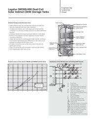
Introduction 1Brief Description of Control OperationThe HS2105 is a heating system controller integrating thefunctions of space heating on outdoor reset using an outdoorsensor, priority domestic hot water heating (DHW) of anindirect fired water heater, periodic operation of a DHWrecirculation pump as well as offering programmable nightsetback for customized operation. Optional modules provide2-stage or dual burner control and outdoor reset control of amotorized mixing valve for floor heating applications.Note: <strong>Buderus</strong> Hydronic Systems, Inc. stronglyrecommends the use of a thermostatic valve on theoutlet of the DHW storage tank to prevent scaldingwhen operating the HS2105 in manual override mode.Two different control methods can be utilized with respect tospace heating. Parameters listed in bold are set on the control.Refer to relevant sections in this manual for more details.Case 1: All heating zones are controlled by on/offthermostats.The space heating operates along a heating curve;figure 1 shows a typical curve. The slope is set by the“REF TEMP” value; the heating curve can be shiftedup or down with the “OFFSET”. The boiler maintainstemperature within the dashed lines of the burnerdifferential. The control uses the difference between thespecified “DAY TEMP” and “NIGHT TEMP” valuesto compute a lower heating curve for night mode operation.200180Ref Temp160140120100OffsetMAX TEMP1BurnerDifferentialPump LogicHeating Curve(day mode)Heating Curve(night mode)On a call for DHW, the control can fire the burner upto the “MAX TEMP 1” setting for maximum recovery.The control temporarily interrupts pump operation withthe burner running when the boiler water temperaturedrops below the “PUMPLOGIC” setting for condensationprotection.806070 60 50 40 30 20 14 10 0 -10 -20 -30OUTSIDETEMPERATURE (˚F)Fig. 1: Typical heating curves for the HS2105 without a room sensor3
1 IntroductionCase 2: Multiple zones with the main zone onconstant circulation200MAX TEMP1Heating Curve(day mode)The heating curve is set in a similar way as in Case 1. Aroom sensor is required in the constant circulation zone toprovide room temperature compensation for fine-tuning ofthe heating curve. The main zone sets the water temperatureavailable to all secondary zones. Specified day and nighttemperatures on the room sensor are used internally tocompute a heating curve during night mode.180Ref Temp16014012010080OffsetBurnerDifferentialRoom SensorCompensation EffectRoom SensorCompensation EffectPump LogicHeating Curve(night mode)6070 60 50 40 30 20 14 10 0 -10 -20 -30OUTSIDETEMPERATURE (˚F)Fig. 2: HS2105 heating curve with room sensor adjustmentCase 3 : Multiple TemperaturesThe heating curve for the high temperature zone(s)is set on CIRCUIT 1. CIRCUIT 2 defines the lowtemperature heating curve using a motorized mixing valve.The HS2105 control positions the mixing valve basedon the outside and supply temperature measured by a strap-onsensor. Each heating circuit can be equipped with an optionalroom sensor.200180Ref Temp160140120Ref Temp10080OffsetMAX TEMP1BurnerDifferentialMax Temp2Pump LogicHeating Curve Circuit 1(day mode)Heating Curve Circuit 1(night mode)Heating Curve Circuit 2(day mode)Heating Curve Circuit 2(night mode)6070 60 50 40 30 20 14 10 0 -10 -20 -30OUTSIDETEMPERATURE (˚F)Fig.3: High and low temperature heating curves; requires module FM2414
Mounting Instructions 2• Remove the front panel of the boiler.• Only necessary with the G124X, G224E, G234X and G334Xboilers.• Remove the two screws and housing from the top of theEcomatic.• Insert the two front feet of the control into the holes providedon the top of the boiler. Then, firmly push down on the rear ofthe control until it snaps into place.• Fasten the control to the boiler jacket using the two screws asshown.• The sensor bundle consists of one thermistor (FK), twocapillaries and a spacer. Mount the sensors per the followingboiler specific instructions. The chrome well is supplied withthe Ecomatic.G115, G205, G305: Replace brass well with chrome Ecomatic well.The sensor bundle must be fully inserted into the Ecomatic well.G124X: Unwrap the sensor bundle. Remove spacers from the chromewell on the boiler. Remove the copper sleeve from one of the capilaries.Install all 3 probes in with the Honeywell capillary.G224E/G234X/G334X: The tridicator assembly should be moved tothe supply piping and replaced with the chrome plated Ecomatic we l l .The sensor bundle must be inserted into this well.5
2 Mounting Instructions• Electrical connections must be made according to the wiringdiagram (See pages 40-46).• All the wires should be routed through the cable raceway at therear of the boiler. Rear panel jacket may be modified per localcode. Route the wires on top of the insulation to the back of thecontrol.• Use the white strain reliefs provided to lock all cables into placeon the back of the control.• Tilt the display to the desired position.• Replace the top housing of the control and fasten the two screws.The control is ready to be placed into operation.6
Testing the <strong>Manual</strong> Reset High Limit (STB) 31. Switch the control onwith the main powerswitch (I Position).R E L A Y S2. Enter the key code(See page 8).3. Turn the dial until “RELAYS”appears in the display.4. Press and hold the button. Turn the dial untilthe display shows “BURNER ON”. The burner starts.Heating pumps will not run during the burner test.Allow the burner to run until burner shuts off at thesetpoint on the aquastat dial.B U R N E R O No F705. Remove the black aquastat dial.180Aquastat Dial6. Push the green button in with screwdriver or similarinstrument to bypass the adjustable boiler aquastat.Hold the green button until the STB or manual resethigh limit trips. This happens at approximately 230°F.Green Button7. Run circulators to remove excess heat. Then, to resetthe STB, remove the safety nut. Press in the resetbutton underneath. This will return the control backto normal operation.o F70To Resume Normal Operation:Press the AUT button.Safety Nut7
4 Key CodeKey CodeThe access to the installation level of the HS2105 controlis protected against unauthorized use by a special keycode. Entry in this level allows you to change settingsdescribed in this manual.This installation level should only be accessed by a heatingcontractor or a trained operator. Entries at this levelidentify to the control the different components of theheating system, specify how these components are to beoperated and set up the proper heating curve(s). Theseentries in general do not require any adjustment. Anyadjustments must be performed by a heating contractoror a trained operator.Key Code Access P rocedure for access to theInstallation Level• Press and hold the lower left hand ENTERbutton.• Insert a pointed object into the hole directlyto the right of the ENTER button.• Release both buttons. The display reads“DEUTSCH” (GERMAN).DEUTSCHTo change the language selection:• Enter the key code. The word “DEUTSCH”(GERMAN) appears in the display.• Press and hold the button.• Turn the dial to select the “AMERICAN”language selection.AMERICANReturned to the Standard Display:• Press the AUT button.Note: The control resumes automatic operation if noentries are made for a period of 5 minutes.8
5 Program OverviewListing of Entries at the Installation LevelAccess to the installation is done using the key code.Display Read-out+DEUTSCHBLR TEMPCIRCUIT 1CIRCUIT 2FREEZTEMPBLDG RESPTWO STAGE*1MIN MOD*2MOD TIME*2PUMPLOGICMAX TEMP1FLUE TEMP*3PERIM-HTGREF TEMPREMOTE 1ROOM COMP*4OASETBACKOFFSETFLOOR-HTGREF TEMPDHWPRIORMAX TEMP2REMOTE 2ROOM COMP*4OASETBACKOFFSETDHWPRODRECIRPUMPHTGCURVE 1HTGCURVE 2RELAYSPage891112131415161718191920-21252627-2822191920-212324252627-28222930313132Language selectionBoiler parametersFrost protection temperatureBuilding heat storage capacityBurner operation detailsMinimum firing rate for a modulating burner *2Modulation time for full mod burner*2Water temperature setting for PumplogicMaximum electronic high limit for boiler temperatureFlue gas warning temperature*3Heating Zone 1 Installation Parameters (unmixed zone)Identifies nature of high temp zone (baseboard, radiators etc.)Reference Temperature for specifying boiler zone reset curveRoom sensor present for unmixed zone yes/noRoom temperature compensation*4Setback mode selectionOffset, vertical shift of reset curveHeating Zone 2 Installation Parameters (mixed zone)*5Identifies nature of low temperature mixed zoneReference Temperature for specifying boiler zone reset curveDHW priority on mixed zone*6Maximum electronic high limit for mixed zoneRoom sensor present for mixed zone yes/noRoom temperature compensation*4Setback mode selectionOffset, vertical shift of reset curveDomestic hot water yes/noDHW recirculation pumpHeating curve for unmixed zoneHeating curve for mixed zoneRelay test on different system componentsBURNERBURNER 2*1), MOD BNR*2HTG1 PUMPHTG2 PUMPMIX VALVE*5)DHW PUMP*6)RECIRPUMP*6)Burner RelayBurner 2 Relay*1), Modulation higher/lower*2)Boiler zone pump (unmixed heating circuit)Mixed zone pump (mixed heating circuit)Mixing valve open/close*5)Tank charging pump*6)DHW recirculation pump*6)LCD- TESTRESETVERSION333435LCD testGeneral system reset to factory settingsControl version number10*1 Applies only with module FM 242 installed and 2 stage burner selected.*2 Applies only with module FM 242 installed and modulating burner selected.*3 Applies only with module KM 271.*4 Applies only with remote sensor installed.*5 Applies only with Module FM 241 installed.*6 Applies only with domestic hot water installed.
Installation Entries 6Freeze Protection: “FREEZTEMP”To prevent the heating system from freezing, the control will automaticallypermit the heating circulators to run continuously in the night mode whenthe outside temperature drops below the “FREEZTEMP” value irrespectiveof the selected setback mode.▲❅The factory setting is 41˚F; the range is 0˚F to 50˚F.To change the FREEZTEMP:• Enter the key code.BLR TEMP• Turn the dial until the word “BLR TEMP” appears in the display.• Press the button and release.The display will show “FREEZTEMP”.• Press and hold the button.The current value of the “FREEZTEMP” is blinking.• Turn the dial until the desired “FREEZTEMP” value appears in the display.Return to the main menu:FREEZTEMP˚F40• Press the return.RETURN TO THE STANDARD DISPL AY:• Press the AUT button.Note: The control resumes automatic operation if no entries are made for aperiod of five minutes.Note 1: The “FREEZTEMP” setting is the determining value when usingthe “OASETBACK” setback mode. The circulators will not operate in nightmode when the outside temperature exceeds the “FREEZTEMP” value. Thecirculators will run constantly for outside temperatures below the“FREEZTEMP” value.Note 2: The “FREEZTEMP” setting is also of significance in terms ofpump operation during the night mode when using room sensors. The heatingcirculators (on circuits 1 and 2) will stop when the actual room temperatureexceeds the desired night temperature AND the outside temperature exceedsthe “FREEZTEMP” value.Freeze Protection: “FREEZTEMP” 0˚F to 50˚F 41˚FRange Factory Setting Current Setting11
6 Installation EntriesBuilding Type: “BLDG RESP”The type of building in terms of insulating factor, heat storing capacityand response to outside temperature changes is specified with the“BLDG RESP” setting.The HS2105 control uses this setting to respond in a delayed fashionto changes in outside temperature and relies on the heat storing capacity tomaintain a comfortable temperature level in the building. The settings aredefined as:1= Buildings with small heat storing capacity and medium levels ofinsulation (Wood construction and medium to heavy insulation).2= Buildings with medium heat storing capacity and high levels ofinsulation (Brick construction with medium insulation).3= Buildings with high heat storing capacity and high levels ofinsulation (Heavy brick construction with good insulation).Note: For areas where rapid changes in outside temperatures occur,it is recommended to always use setting 1 irrespective of the type ofconstruction.To change the “BLDG RESP”setting:• Enter the key code.BLR TEMP• Turn the dial until the word “BLR TEMP” appears in the display.• Press the button and release. The display will show “FREEZTEMP”.• Turn the dial until the word “BLDG RESP” appears in the display.• Press and hold the button.The current value of the “BLDG RESP”setting is blinking.• Turn the dial until the desired “BLDG RESP” value appears in the display.Re t u rn to main menu:BLDG RESP2• Press thebutton.R E T U R N TO T H E S TA N D A R DD I S P LAY• Press the AUT button.12Freeze Protection: “FREEZTEMP” 1,2,3 2Range Factory Setting Current Setting
Installation Entries 6Burner Installation: “BURNER”The burner module FM242 must be installed for this submenu to appear.The factory setting without the FM242 module is “ONE STAGE”.However, this setting does not become visible in the display when moduleFM242 is not installed.The HS2105 control automatically switches from single stage to two stagewhen the FM242 module is inserted. One can select at this point between aone stage burner, two stage burner (or dual boiler/burner system) ormodulating burner.Note: In case a two stage burner (or dual boiler system) isselected, separate burner run times will be displayed.To change the “ BURNER” setting:• Enter the key code.• Turn the dial until the word “BLR TEMP” appears in the display.• Press the button and release.The display will show “FREEZTEMP”.BLR TEMP• Turn the dial until the word “TWO S TAGE” appears in the display.• Press and hold the button.The adjustable parameter is blinking.TWO STAGE• Turn the dial until the word “MOD BRNR” appears in thedisplay for a modulating burner.Return to main menu:• Press thebutton.R E T U R N TO T H E S TA N D A R DD I S P LAYMOD BRNR• Press the AUT button.Range Factory Setting Current SettingBurner System without FM242 module1-stageBurner System with FM242 module 1-stage/2-stage/modulating 2-stage13
6 Installation EntriesMinimum Fi ring Rate for a Modulating B u rner: “MIN MOD”The installation of the burner module FM242 and the selection of amodulating burner (“MOD BRNR”) are required in order for thissubmenu to appear. The minimum firing rate of the burner modulationis specified in this setting.The factory setting is 30%.To change the “MIN MOD” setting:• Enter the key code.• Turn the dial until the word “BLR TEMP” appears in the display.• Press the button and release.The display will show “FREEZTEMP”.• Turn the dial until the word “MIN MOD” appears in the display.• Press and hold the button.The current value of the “MIN MOD” is blinking.MIN MOD30• Turn the dial until the desired “MIN MOD” value appears inthe display.Return to main menu:• Press thebutton.R E T U R N TO T H E S TA N D A R DD I S P LAY• Press the AUT button.MIN MOD4014Minimum Modulation “MIN MOD” 10% to 60% 30%Range Factory Setting Current Setting
Installation Entries 6Modulating Valve Operating Time for the Modulating Burner:“MOD TIME”The installation of the burner module FM242 and the selection of amodulating burner (“MOD BRNR”) are required in order for this submenuto appear. The modulating valve operating time is the total time in secondsrequired for the modulating burner to go through its full operating range.The factory setting is 12 seconds.To change the “MOD TIME” setting:• Enter the key code.• Turn the dial until the word “BLR TEMP” appears in the display.• Press the button and release.The display will show “FREEZTEMP”.• Turn the dial until the word “MOD TIME” appears in the display.• Press and hold the button.The current value of the adjustable parameter is blinking.• Turn the dial until the desired valve operating time“MOD TIME” appears in the display.MOD TIME12Return to main menu:• Press thebutton.MOD TIME15R E T U R N TO T H E S TA N D A R DD I S P LAY• Press the AUT button.Valve Operating Time “MOD TIME” 5 sec - 60 sec 12 secRange Factory Setting Current Setting15
6 Installation EntriesCondensate Protection Feature: “PUMPLOGIC”The HS2105 control has a built in feature called “PUMPLOGIC” where the control interrupts circulatoroperation when the burner fires into a cold boiler. Once a specified temperature is reached in the boiler, thepumps are permitted to run. This temperature is adjustable and set with the “PUMPLOGIC” setting.The factory setting is:104˚F for a one stage burner113˚F for a two stage burner122˚F for a modulating burnerTo change the “PUMPLOGIC” setting:• Enter the key code.• Turn the dial until the word “BLR TEMP” appears in the display.• Press the button and release.The display will show “FREEZTEMP”.• Turn the dial until the word “PUMPLOGIC” appears in the display.• Press and hold the button.The current value of “PUMPLOGIC” is blinking.• Turn the dial until the desired value for “PUMPLOGIC” appearsin the display. Consult the table below for your boiler model.Table 1: Minimum “PUMPLOGIC” valuesBoiler Series 1 - STAGE 2 - STAGE MODULATINGG115,G205, G305 104 N/A N/AG315 122 131 131G515 122 131 131G124X 104 N/A N/AG234X/G334X 104 122 N/APUMPLOGICPUMPLOGIC˚F104˚F130Note: The minimum burner shut-off temperature always exceeds the “PUMPLOGIC” value by 9˚F.Return to main menu:• Press the button.RETURN TO THE STANDARD DISPLAY• Press the AUT button.Note: The control resumes automatic operation if no entries are made for a period of five minutes.Pump Shut-offTemp. “PUMPLOGIC” 59-140˚F 104˚F16Range Factory Setting Current Setting
Installation Entries 6Maximum Burner Shut-off Temperature:“MAX TEMP1”A maximum temperature is specified above which the electronic boiler sensorshuts off the burner. This setting is not operative when the control is operating inthe manual mode using the emergency override switch. The adjustable capillaryhigh limit shuts off the burner in manual override mode.The factory setting is 176˚F.To change the “MAX TEMP1” setting:• Enter the key code.• Turn the dial until the word “BLR TEMP” appears in the display.• Press the button and release.The display will show “FREEZTEMP”.• Turn the dial until the word “MAX TEMP1” appears in the display.• Press and hold the button.The current value of “MAX TEMP1” is blinking.• Turn the dial until the desired value for “MAX TEMP1” appears inthe display.MAX TEMP1˚F176Return to main menu:• Press the button.R E T U R N TO T H E S TA N D A R DD I S P LAY• Press the AUT button.MAX TEMP1˚F193Maximum Boiler Shut-offTemperature 158 - 210˚F 176˚FRange Factory Setting Current Setting17
6 Installation EntriesFlue Gas Temperature Sensing: “FLUE TEMP ”Module KM271 must be installed for this submenu to appear. The flue gastemperature can only be measured and shown in the display when the KM271module is installed in the HS2105 control. The flue gas temperature can beviewed in the display.When an ECOKOM communication system and modem is installed, a servicemessage is transmitted when the flue gas temperature exceeds a preset value. Theboiler will require maintenance. The flue gas sensing capability must be activatedwhen the KM271 module has been installed.The factory setting is “OFF”.To change the “FLUE TEMP” setting:• Enter the key code.• Turn the dial until the word “BLR TEMP” appears in the display.• Press the button and release.The display will show “FREEZTEMP”.• Turn the dial until the word “FLUE TEMP” “OFF” appears in the display.• Press and hold the button.The adjustable parameter is blinking.• Turn the dial until the desired flue gas temperature is shown inthe display above which a service message would be transmitted.Return to main menu:• Press thebutton.RETURN TO THE STANDARD DISPLAY• Press the AUT button.Note : The control resumes automatic operation if no entries are made for a periodof 5 minutes.FLUE TEMPFLUE TEMPOFF˚F48018Flue Gas Temperature “FLUE TEMP” OFF/120-480˚F OFFRange Factory Setting Current Setting
Installation Entries 6Heating System Lay-outThe HS2105 control is designed for individual control of two heating circuits with different water temperatures. Thesecond heating circuit is only possible when the mixing module FM241 has been installed. The nature of each heatingcircuit must be specified to the control. For example, baseboard heating on circuit 1 and radiant floor heating on circuit 2.The HS2105 control needs this information to set the proper curvature for the different heating curves.Circuit 1 Options:• “PERIM-HTG” Circuit 1 operates on a reset curve for perimeter heatingsuch as baseboard or radiators (Range 86˚F-194˚F).• “NO SYSTEM” Circuit 1 follows circuit 2 reset curve. This optioncan only be selected when module FM241 is installed.The boiler operates 9˚F above the circuit 2requirements.CIRCUIT 1Circuit 2 Options:• “PERIM-HTG” Circuit 2 operates on reset curve for perimeter heating(Range 86˚F-194˚F).• “FLOOR-HTG” Circuit 2 operates on a reset curve suitable for radiant floorheating (Range 86˚F-140˚F).• “NO SYSTEM”Circuit 2 follows the same reset curve as specified for circuit 1.To change the heating circuit descriptions:PERIM-HTGNO SYSTEMFLOOR-HTG• Enter the key code.• Turn the dial until the word “CIRCUIT 1” or “CIRCUIT 2” appearsin the display.CIRCUIT 2PERIM-HTG• Press the button and release. The display will show “PERIM-HTG”.• Press and hold the button. The adjustable parameter is blinking.NO SYSTEM• Turn the dial until the desired heating circuit description appears in thedisplay.Return to main menu:• Press the button.Note: In case module FM241 is installed, repeat the “Turn the dial” step until the word “CIRCUIT 2” appears in the display.Repeat the steps above to properly define circuit 2.RETURN TO THE STANDARD DISPLAY• Press the AUT button.Range Factory Setting Current SettingCIRCUIT 1 PERIM-HTG/NO SYSTEM PERIM-HTGCIRCUIT 2 PERIM-HTG/FLOOR-HTG/NO SYSTEM FLOOR-HTG19
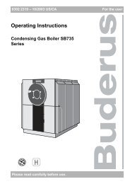
6 Installation EntriesHeating Curve Selection: Setting the Reference TemperatureThe heating curve establishes the relationship between the outsideair and boiler water temperatures. The boiler water is automaticallylowered at warmer outside temperatures and raised at colder outsidetemperatures.The correct heating curve is determined by the characteristics of thehouse (i.e., type of radiation, degree of insulation, heating systemdesign temperatures, etc.) Baseboard systems are generally designedto operate at 190˚F on design day. The figure below shows a number ofheating curves for different design temperatures.REF TEMP˚F167To select the proper curve, one must always specify the desired water temperature for an outside temperature of 14˚F. Thecorresponding water temperature is the “REF TEMP” setting. The HS2105 control then automaticallycreates a curve for all outside temperatures.Heating Curve AdjustmentsThe “REF TEMP” fine adjustment should be done based on cold weather performance. Increase the “REF TEMP” value if theroom temperature is too low during cold weather. Decrease the “REF TEMP” setting if overheating tends to occur. Make onlyminor adjustments and allow ample time for the system to respond.Example: “REF TEMP” Selection:Assume a panel radiator is designed with amaximum water temperature of 176˚F for a-20˚F design day. Locate the point where 176˚Fwater temperature intersects -20˚F outsidetemperature. Draw a curve from this point to thestarting point (68˚). Now enter the chart at the 14˚Fpoint and move vertically until you intersect yourcurve. Now move horizontallyto the left to find your “REF TEMP”. In this case itwould be approximately 142˚F.BOILERWATERTEMPERATURE (°F)194176167158140122104866868 59 500 -10 -20 -30 -4041 32 23 14 5 -4 -13 -22 -31 -40OUTSIDE TEMPERATURE (°F)20
Installation Entries 6Heating Curve Selection: Setting the “REF TEMP”The “REF TEMP” setting is adjustable from 86˚F to 194˚F. The slopeof the heating curve changes as the “REF TEMP” value is changed.The factory setting is 167˚F for “PERIM-HTG” circuits and 113˚F for“FLOOR-HTG” circuits.To change the “REF TEMP” settings• Enter the key code.• Turn the dial until the word “CIRCUIT 1” or “CIRCUIT 2” appearsin the display.REF TEMP˚F167• Press the button and release.The display will show “PERIM-HTG” or “FLOOR-HTG”.• Turn the dial until the word “REF TEMP” appears in the display.• Press and hold the button.The current value for “REF TEMP” is blinking.• Turn the dial until the desired value for “REF TEMP” appears inthe display.Return to main menu:REF TEMP˚F140• Press the button.RETURN TO THE STANDARD DISPLAY• Press the AUT button.• Repeat above procedure for “CIRCUIT 2” if module FM241 is installed.Note: The control resumes automatic operation if no entries are made for a period of 5 minutes.Note: In case the maximum design temperature for the radiant floor system exceeds 140˚F, you must select“PERIM-HTG” for circuit 2 to reach sufficiently high water temperatures.Range Factory Setting Current Setting“REF TEMP” for “PERIM-HTG” 86˚F - 194˚F 167˚F“REF TEMP” for “FLOOR-HTG” 86˚F - 140˚F 113˚F21
6 Installation EntriesVertical Shifting of the Heating Cur ve: “OFFSET”The “OFFSET” entry can be used to parallel shift a heating curve upward ordownward. Every + 1˚F adjustment in the “OFFSET” results in a +2 or +3˚Fincrease in water temperature. A maximum upshift in water temperature ofapproximately 25 to 30˚F is achieved with the “OFFSET” equal to +9˚F (seeFig. 1 on page 3).The factory setting is 0.To change the “OFFSET” value:• Enter the key code.• Turn the dial until the word “CIRCUIT 1” or “CIRCUIT 2” appearsin the display.• Press the button and release.The display will show “PERIM-HTG” or “FLOOR-HTG”.• Turn the dial until the word “OFFSET” appears.• Press and hold the button.The current value of “OFFSET” is blinking.• Turn the dial until the desired value for “OFFSET” is shown inthe display.Return to main menu:• Press the button.RETURN TO THE STANDARD DISPLAY• Press the AUT button.Note: The control resumes automatic operation if no entries are made for aperiod of 5 minutes.OFFSETOFFSET˚F0˚F422Range Factory Setting Current Setting“OFFSET” value for Circuit 1 -9˚F - 9˚F 0˚F“OFFSET” value for Circuit 2 -9˚F - 9˚F 0˚F
Installation Entries 6Domestic Hot Water Priority for Circuit 2 : “DHW PRIOR”The HS2105 control automatically grants domestic hot water (DHW) priority over heating circuit 1. In other words, ona call for domestic hot water, the control temporarily shuts off the circulator for heating circuit 1, fires the burner andruns the tank circulator.If Module FM241 is installed in the control, one can select whether to have DHW priority over circuit 2 or to operatecircuit 2 in parallel. If DHW priority over circuit 2 is selected, the mixing valve closes during heating of domestic hotwater. If parallel operation is desired, the mixing valve continues operation and longer DHW heating times can be expected.The factory setting for “DHW PRIOR” is “ON”.To change the “DHW PRIOR” setting:• Enter the key code.• Turn the dial until the word “CIRCUIT 2” appears in the display.DHW PRIORON• Press the button and release. The display will show“NO SYSTEM”, “PERIM-HTG” or “FLOOR-HTG”.• Turn the dial until the words “DHW PRIOR” “OFF” appear.• Press and hold the button. The current value is blinking.• Turn the dial until the desired value is shown in the display.DHW PRIOROFFNote: The DHW setting in the main menu must be turned “ON” inorder for the above submenu to appear.Return to main menu:• Press the button.RETURN TO THE STANDARD DISPLAY• Press the AUT button.Note: The control resumes automatic operation if no entries are made for aperiod of 5 minutes.Range Factory Setting Current Setting“DHW PRIOR” (for Circuit 2 only) ON/OFF ON23
6 Installation EntriesMaximum Heating Circuit 2 Temperature: “MAX TEMP2”The maximum temperature in heating circuit 2 is specified in “MAXTEMP2” and shall not exceed this value.The factory settings for circuit 2 are:for “PERIM-HTG” 194˚Ffor “FLOOR-HTG” 122˚FTo change the “MAX TEMP2” setting:• Enter the key code.• Turn the dial until the word “CIRCUIT 2” appears in the display.• Press the button and release.The display will show “PERIM-HTG” or “FLOOR-HTG”.• Turn the dial until the word “MAX TEMP2” appears in the display.• Press and hold the button.The current value of “MAX TEMP2” is blinking.• Turn the dial until the desired value is shown in the display.Return to main menu:• Press the button.RETURN TO THE STANDARD DISPLAY• Press the AUT button.Note: The control resumes automatic operation if no entries are made for aperiod of 5 minutes.MAX TEMP2MAX TEMP2˚F194˚F140Range Factory Setting Current SettingMax Temperature for Circuit 2 PERIM – HTG 68˚F - 194˚F 194˚FMax Temperature for Circuit 2 FLOOR – HTG 68˚F - 140˚F 122˚F24
Installation Entries 6Room Sensor: “REMOTE ”The room sensor is an optional indoor temperature sensor which is required when using a constant circulation zone.A maximum of 2 room sensors can be installed on the system; one for a constant circulation zone for circuit 1 and onefor a constant circulation zone for circuit 2. If no room sensors are installed, the system operates using only outsidetemperature as a reference and requires conventional thermostats to control pumps/zone valves.The room sensor performs a correction or compensation on the boiler water temperature based on the deviation betweenthe actual and desired room temperature. The room sensor allows setting of day temperature and night setback as well asremotely overriding the customized heating program. The room sensor also performs a “boost” during transition to day mode.The room sensor selection must be activated for use.The factory setting is “OFF”.To activate the room sensor(s):• Enter the key code.• Turn the dial until the word “CIRCUIT 1” or “CIRCUIT 2” appears inthe display.• Press the button and release.The display will show “PERIM-HTG” or “FLOOR-HTG”.• Turn the dial until the word “REMOTE 1” or “REMOTE 2” appearsin the display.• Press and hold the button. The adjustable parameter is blinking.• Turn the dial until the word “ON” appears in the display.Return to main menu:• Press the button.RETURN TO THE STANDARD DISPLAY• Press the AUT button.REMOTE 1REMOTE 1OFFONNOTICE: If a room sensor is installed on either circuit 1 or circuit 2, then the desired day and night temperatures can only beset on the room sensor and no longer on the HS2105 control itself. The buttons on the HS2105 itself are no longer functionalfor this circuit. Pressing the temperature button on the HS2105 will indicate that a room sensor is installed on the system. Thebuttons on the HS2105 apply now only to the heating circuit without a room sensor. The day and night temperatures are set onthe HS2105 only for this circuit.Range Factory Setting Current SettingRemote Sensor CIRCUIT 1 OFF/ON OFFRemote Sensor CIRCUIT 2 OFF/ON OFF25
6 Installation EntriesAdjusting the Room Temperature Compensation: “ROOM COMP”.The room sensor compensates for swings in room temperature (i.e. solar gain,internal heat gain, open windows) by adjusting the water temperature in itsparticular zone. The range of compensation is adjustable and limits the effect ofthe room sensor on the water temperature.The factory setting is 5˚F.Note: When “OFF” is selected, the room sensor does not have any effecton the heating curve where it is placed. The constant circulation pumpcontinues to operate.To change room temperature compensation: “ROOM COMP”:• Enter the key code.• Turn the dial until the words “CIRCUIT 1” or “CIRCUIT 2” appearin the display.• Press the button and release.The display will show “PERIM-HTG” or “FLOOR-HTG”.• Turn the dial until the word “ROOM COMP” appears in the display.• Press and hold the button.The current value of “ROOM COMP” is blinking.• Turn the dial until the word “OFF” or the desired amount of “ROOMCOMP” appears in the display.Return to main menu:• Press the button.RETURN TO THE STANDARD DISPLAY• Press the AUT button.Note: The control resumes automatic operation if no entries are made fora period of 5 minutes.ROOM COMPROOM COMP5˚F˚F1026Range Factory Setting Current SettingRoom compensation for CIRCUIT 1 OFF/ 1 - 18˚F 5˚FRoom compensation for CIRCUIT 2 OFF/ 1 - 18˚F 5˚F
Installation Entries 6Setback Mode SelectionThe HS2105 control contains night setback capability and allows you to select from 4 different types or modes ofnight setback for customized operation. These setback modes differ in their operation during setback periods.Night Setback OptionsThe factory setting is “OASETBACK”.1 Boiler Off (“BLR OFF”)In this mode the heating system shuts down completely during thenight time as long as the outside temperature exceeds the “FREEZTEMP”setting. Below the “FREEZTEMP” value, the circulators run in freezeprotection mode. The boiler only fires if the water temperature drops below41˚F. Again, no room sensors are used when using this setback mode.2 General Setback (“SETBACK”)The heating circulators continue operation in the “SETBACK” mode; theboiler operates on a lower heating curve and fires the burner as needed. T h i smode is generally used when no room sensors are pre s e n t and individual zonesare controlled by conventional thermostats.3 Room Setback (“RMSETBACK”)This setback mode should only be selected when a room sensor is installed andactivated. The system operates to maintain the desired night time temperatureas specified on the room sensor. The circulators will operate continuously whenthe outside temperature is below the “FREEZTEMP” setting; the circulatorsshut down when the outside temperature is above the “FREEZTEMP” settingand the actual room temperature exceeds the night time setting.4 Outside Air Setback (“OASETBACK”)The heating system (burner and heating circulators) shuts down innight mode if the outside temperature exceeds the “FREEZTEMP”; ifthe outside temperature drops below the “FREEZTEMP”, the heatingsystem operates on a setback curve. This mode should only be usedon buildings not occupied in the night mode; i.e. commercial anddaytime use only buildings. A room sensor is generally not used inthis application.BLR OFFSETBACKRMSETBACKOASETBACKRecommended Settings:Heating circuit with constant circulation zone :Heating Circuit with ON/OFF thermostats:Commercial (day use only) buildings:RMSETBACKSETBACKOASETBACK27
6 Installation EntriesTo Change the Setback Mode Setting:• Enter the key code.• Turn the dial until the word “CIRCUIT 1” or “CIRCUIT 2” appears in the display.• Press the button and release.The display will show “PERIM-HTG” or “FLOOR-HTG”.• Turn the dial until the word “OASETBACK” appears in the display.OASETBACK• Press and hold the button.The adjustable parameter is blinking.• Turn the dial until the desired setback mode appears in the display.Return to main menu:• Press the button.SETBACKRETURN TO THE STANDARD DISPLAY• Press the AUT button.Note: The control resumes automatic operation if no entries are made for aperiod of 5 minutes.28Setback Modes for CIRCUIT 1Setback Modes for CIRCUIT 2Range Factory Setting Current SettingOASETBACK/SETBACK/RMSETBACK/BLR OFFOASETBACKOASETBACK/SETBACK/RMSETBACK/BLR OFFOASETBACK
Installation Entries 6Domestic Hot Water Production Capability: “DHW PROD”The HS2105 is set up to have an indirect fired water tank installed inthe system. The DHW portion of the control is activated.The factory setting is “ON”.In case no indirect fired DHW tank is installed in the system, the DHWproduction must be shut off. In case the DHW is not turned off, a “DHWSENSR” error message will appear in the display because the DHWsensor is not installed.To shut off the DHW feature of the HS2105 control:• Enter the key code.• Turn the dial until the word “DHW PROD” appears in the display.• Press and hold the button.The adjustable parameter is blinking.• Turn the dial until the word “OFF” appears in the display.Return to main menu:• Press the button.RETURN TO THE STANDARD DISPLAY• Press the AUT button.Note: The control resumes automatic operation if no entries are made for aperiod of 5 minutes.Note: In case the DHW capability is activated, a DHW recirculation pump (ifinstalled) can be controlled.DHW PRODDHW PRODONOFFRange Factory Setting Current SettingDHW Capability “DHW PROD” OFF / ON ON29
6 Installation EntriesDHW Recirculation Pump “RECIRPUMP”The HS2105 can operate a DHW recirculation pump for constantsupply of domestic hot water at faucets. This recirc pump is simultaneouslyactivated with the DHW production and runs concurrent with day modeoperation for DHW.This recirculation pump can be set up to operate continuously orintermittently. This pump is operational when at least one heatingcircuit is operating in day mode or when DHW production is inconstant day mode.The recirculation pump operates continuously in the “ON” position.The factory setting is 2.A setting of 2 means that the recirculation pump runs twice every hour fora three minute interval. One can select from 1 to 6 intervals per hour forcustomized operation.To change the inter val run time for the recirculation pump:• Enter the key code.• Turn the dial until the word “RECIRPUMP” appears in the display.• Press and hold the button.The adjustable parameter is blinking.• Turn the dial until the desired number of intervals per hour, “ON” or“OFF” appears in the display.Return to main menu:• Press the button.RETURN TO THE STANDARD DISPLAY• Press the AUT button.Note: The control resumes automatic operation if no entries are made fora period of 5 minutes.3 minutes 31 HourRECIRPUMPRECIRPUMPONOFF2430Range Factory Setting Current SettingDHW Recirculation “RECIRPUMP” OFF /1/2/3/4/5/6/ON 2
Display of Heating Curves 7The current heating curves for circuit 1 and circuit 2 (if module FM241is installed) can be displayed by showing three water temperatures for eachcircuit at outside temperatures of 50˚F, 32˚F and 14˚F based oncurrent system settings.To display the heating cur ve for circuit 1 or circuit 2:• Enter the key code.• Turn the dial until the word “HTG CURVE 1” or “HTG CURVE 2”appears in the display.• Press and hold the button.• The first screen shows the water temperature at 50˚F outsidetemperature, turning the dial shows the water temperature at 32˚Fand the third display shows the water temperature at 14˚F outsidetemperature. Keep the button down during these steps.Return to main menu:• Press the button.HTG CURVE 1113HTG CURVE 1145HTG CURVE 1167˚F50˚F32˚F14RETURN TO THE STANDARD DISPLAY• Press the AUT button.Note: The control resumes automatic operation if no entries are made for aperiod of 5 minutes.31
8 Testing of RelaysTesting of All Relays of the HS2105 Control : “REL AYS”The switching relays in the HS2105 control can individually be tested with the “RELAYS” test. This test is alsouseful to verify that circulators, burner(s) and mixing valve(s) are properly wired to the control. The actual relaysavailable for testing depend on the modules inserted into the control.The following relays can be tested:• Burner first stage second stage• Burner Modulationopen/close• Circuit 1 Heating Pump on/off• Circuit 2 Heating Pump on/off• Mixing Valveopen/close• DHW charging Pump on/off• DHW Recirculation Pump on/offTo perform the “REL AYS” test:• Enter the key code.• Turn the dial until the word “RELAYS” appears in the display.• Press and hold the button.RELAYS• Turn the dial until the display reads “BURNER ON”.The Burner comes on.• Release the button.If the burner is functioning properly, the burner symbol appears in the display.• To access and display another relay, turn the dial without pressingthe button.• To test this relay, press and hold the button and turn the dialto activate the relay.All relays can be tested sequentially and the switched status is displayed by anidentifying symbol.Return to main menu:• Press the button.RETURN TO THE STANDARD DISPLAY• Press the AUT button.BURNERBURNEROFFONNote: The control resumes automatic operation if no entries are made for a period of 5 minutes.32
LCD Test 9LCD Test:One can verify with the LCD test if all digits and displays arefunctioning properly:• Enter the key code.• Turn the dial until the word “LCD TEST” appears in the display.• Press and hold the button.• Turn the dial to ensure that all digits and symbolsappear correctly in the display.All digits and symbols must appear fully in the display.RETURN TO THE STANDARD DISPLAY• Press the AUT button.Note: The control resumes automatic operation if no entries aremade for a period of 5 minutes.33
10 Total System ResetRESETAn overall system “RESET” returns all parameters back to the originalfactory settings.To perform a total system “RESET”:• Enter the key code.• Turn the dial until the word “RESET” appears in the display.RESET• Press the button and hold. Continue to hold thebutton until all “8” characters disappear in the display.NOTE: If the button is released before all “8” characters havedisappeared, no system reset has been performed.RESET• Release the button. The “8” characters reappear to signifythat the system reset is complete.RESETRETURN TO THE STANDARD DISPLAY• Press the AUT button.Note: The control resumes automatic operation if no entries are made for a period of5 minutes.34
Version Number 11Version NumberThe version number is a manufacturer’s identification number thatprovides product information regarding the control panel. It isrecommended to write down this version number in case of futurereclamation issues.To access the Version Number:• Enter the key code.• Turn the dial until the word “Version” appears in the displayVERSION211• Write down the specific version number.VERSION NUMBER : ___________________RETURN TO THE STANDARD DISPLAY• Press the AUT button.Note: The control resumes automatic operation if no entries are madefor a period of 5 minutes.35
12 Trouble Shooting ProceduresThe HS2105 has built-in self diagnostics software which continually monitors sensor inputs to ensure thatmeasured values are within acceptable limits, monitors response of system components and signals descriptiveerror messages if these conditions are not met.Message (ERR) Meaning ActionBURNER Burner lock-out Check burner and press burner reset.BLR SENSR Defective FK sensor Check resistance of FK boiler sensor andverify with curve.OA SENSOR Defective outside air sensor Check resistance of OA sensor andverify with curve.DHW SENS Defective DHW sensor Check resistance of FB sensor andverify with curve.MIX SENSR De f e c t i ve mixed circuit sensor (FV) Check resistance of FV sensor and verifywith curve .Check sensor placement and wiring.R E M OT E1 / 2 No n - Responding Room Se n s o r s Check wiring to room sensor (wire 1 to 1, wire 2 to2). If lights on room sensor blink, check HKdial internal on room sensor. Check if roomsensor is activated on HS2105HEATING Heating system stays cold. Turn control OFF/ON.Continued pump logic operation. Check boiler operation.Check manual high limit reset.DHW DHW stays cold for 2 hours. Check tank pump operation and system piping.These messages are very helpful in troubleshooting the HS2105. The control continues burner and circulatoroperation in case of sensor failure to prevent possible freeze-up of the heating system.36
Parameter Settings at the Installation Level 13Record your specific settings at the installation level on this page for future reference. Observe that not allentries listed may actually be accessible as it depends on the modules inserted in the HS2105 and the valueof certain parameters.Parameter Range Factory Setting Actual SettingLanguageDeutschReference Temperature PERIM-HTG 86˚F - 194˚F 167˚FReference Temperature FLOOR-HTG* 86˚F - 140˚F 113˚FFreeze Protection 0˚F - 50˚F 34˚FRoom Sensor OFF / ON OFFRoom Compensation OFF / 1 - 18˚F 5˚FNight Setback Modes Outside Setback OASETBACKSetbackRoom SetbackBoiler OffMaximum Circuit 1 Temperature 158 - 210˚F 176˚FMaximum Circuit 2 Temperature* 68 - 140˚F 122˚F for FLOOR-HTG68 - 194˚F 194˚F for PERIM-HTGFlue Gas Temperature** OFF/120˚F - 480˚F OFFOffset : Vertical Shift of Heating Curve -9˚F - 9˚F 0˚FHeating Circuit 1 NO SYSTEM/PERIM-HTG PERIM-HTGHeating Circuit 2* NO SYSTEM/PERIM-HTG FLOOR-HTGFLOOR-HTGDHW Production ON/OFF ONDHW recirculation Pump OFF/1/2/3/4/6/ON 2Burner System*** 1 stage/2 stage /modulating ONE-STAGEModulation Range*** 10% - 60% 30%Modulating Valve Operating Time*** 5 sec. - 60 sec. 12 sec.Pumplogic (Condensate Protection) 59˚F - 140˚F 104˚FBuilding Response 1/2/3 2DHW Prior ON/OFF ON*Requires Mixing Module FM 241**Requires Communications Module KM 271***Requires Burner Module FM 24237
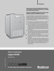
14 Sensor Curves (General)Switch the power off before taking any measurements. Remove sensors from the back of the Ecomatic and measurethe resistance of the cable ends. The curves show mean values and are subject to deviations.Outdoor temperature sensor (FA)5 14 23 32 41 50 59Outdoor Temperature (˚F)Boiler, domestic hot water and mixed circuit supply temperature sensors (FK, FB, FV)68 86 104 122 140 158 176 19438Boiler Water Temperature (˚F)
Sensor Curves 14Room Temperature Sensor (BF)41 50 59 68 77 86Room Temperature (°F)Note: The resistance of the room sensor can only be measured when an external sensor is connected to theEXT terminals in the room sensor. Measure at the EXT terminals with the room sensor disconnected fromthe HS2105 control.39
4015 Wiring Diagrams
Wiring Diagrams 1541
4215 Wiring Diagrams
Wiring Diagrams 1543
4415 Wiring Diagrams
Wiring Diagrams 1545
4615 Wiring Diagrams