Digital Video Camera Module - JenCam GmbH
Digital Video Camera Module - JenCam GmbH
Digital Video Camera Module - JenCam GmbH
You also want an ePaper? Increase the reach of your titles
YUMPU automatically turns print PDFs into web optimized ePapers that Google loves.
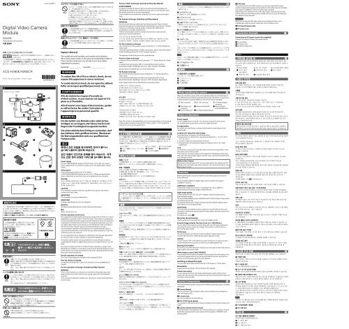
<strong>Digital</strong> <strong>Video</strong> <strong>Camera</strong><strong>Module</strong>Operating Instructions 114-293-946-21(1)XCG-H280E/H280CR© 2011 Sony Corporation Printed in JapanA / <strong>Camera</strong> /BDC C Owner’s RecordThe model and serial numbers are located on the bottom.Record the serial number in the space provided below. Refer tothese numbers whenever you call upon your Sony dealerregarding this product.Model No. _____________WARNINGSerial No. ______________To reduce the risk of fire or electric shock, do notexpose this apparatus to rain or moisture.To avoid electrical shock, do not open the cabinet.Refer servicing to qualified personnel only.AVERTISSEMENTAfin de réduire les risques d’incendie oud’électrocution, ne pas exposer cet appareil à lapluie ou à l’humidité.Afin d’écarter tout risque d’électrocution, garderle coffret fermé. Ne confier l’entretien del’appareil qu’à un personnel qualifié.WARNUNGUm die Gefahr von Bränden oder elektrischenSchlägen zu verringern, darf dieses Gerät nichtRegen oder Feuchtigkeit ausgesetzt werden.Um einen elektrischen Schlag zu vermeiden, darfdas Gehäuse nicht geöffnet werden. ÜberlassenSie Wartungsarbeiten stets nur qualifiziertemFachpersonal.Power SupplyThe XCG-H280E/H280CR operate on DC12V power. In the USA, use a Class 2power supply which is UL Listed. In Canada, use a CSA-certified Class 2 powersupply.AlimentationAvertissement pour les États-Unis et le CanadaLa XCG-H280E/H280CR fonctionne sur du 12 V CC. Utilisez une alimentationclasse 2 répertoriée UL (aux États-Unis) ou homologuée CSA (au Canada).CAUTIONThis installation should be made by a qualified service person and shouldconform to all local codes.IMPORTANTThe nameplate is located on the bottom.IMPORTANTLa plaque signalétique se situe sous l’appareil.WICHTIGDas Namensschild befindet sich auf der Unterseite des Gerätes.For the customers in the U.S.A.This equipment has been tested and found to comply with the limits for a Class Adigital device, pursuant to Part 15 of the FCC Rules. These limits are designed toprovide reasonable protection against harmful interference when the equipmentis operated in a commercial environment. This equipment generates, uses, andcan radiate radio frequency energy and, if not installed and used in accordancewith the instruction manual, may cause harmful interference to radiocommunications. Operation of this equipment in a residential area is likely tocause harmful interference in which case the user will be required to correct theinterference at his own expense.You are cautioned that any changes or modifications not expressly approved inthis manual could void your authority to operate this equipment.All interface cables used to connect peripherals must be shielded in order tocomply with the limits for a digital device pursuant to Subpart B of Part 15 of FCCRules.This device complies with Part 15 of the FCC Rules. Operation is subject to thefollowing two conditions: (1) this device may not cause harmful interference, and(2) this device must accept any interference received, including interference thatmay cause undesired operation.For the customers in CanadaThis Class A digital apparatus complies with Canadian ICES-003.Pour les clients au CanadaCet appareil numérique de la classe A est conforme à la norme NMB-003 duCanada.For the customers in Europe, Australia and New ZealandWARNINGThis is a Class A product. In a domestic environment, this product may causeradio interference in which case the user may be required to take adequatemeasures.In the case that interference should occur, consult your nearest authorized Sonyservice facility.Pour les clients en Europe, Australie et Nouvelle-ZélandeAVERTISSEMENTIl s’agit d’un produit de Classe A. Dans un environnement domestique, cetappareil peut provoquer des interférences radio, dans ce cas l’utilisateur peutêtre amené à prendre des mesures appropriées.Si des interférences se produisent, contactez votre service après-vente agrééSony.Für Kunden in Europa, Australien und NeuseelandWARNUNGDies ist eine Einrichtung, welche die Funk-Entstörung nach Klasse A besitzt.Diese Einrichtung kann im Wohnbereich Funkstörungen verursachen; in diesemFall kann vom Betreiber verlangt werden, angemessene Maßnahmendurchzuführen und dafür aufzukommen.Sollten Funkstörungen auftreten, wenden Sie sich bitte an den nächstenautorisierten Sony-Kundendienst.For the customers in EuropeThe manufacturer of this product is Sony Corporation, 1-7-1 Konan, Minato-ku,Tokyo, Japan.The Authorized Representative for EMC and product safety is Sony Deutschland<strong>GmbH</strong>, Hedelfinger Strasse 61, 70327 Stuttgart, Germany.This apparatus shall not be used in the residential area.Pour les clients en EuropeLe fabricant de ce produit est Sony Corporation, 1-7-1 Konan, Minato-ku, Tokyo,Japon.Le représentant autorisé pour EMC et la sécurité des produits est SonyDeutschland <strong>GmbH</strong>, Hedelfinger Strasse 61, 70327 Stuttgart, Allemagne.Ne pas utiliser cet appareil dans une zone résidentielle.Für Kunden in EuropaDer Hersteller dieses Produkts ist Sony Corporation, 1-7-1 Konan, Minato-ku,Tokyo, Japan.Der autorisierte Repräsentant für EMV und Produktsicherheit ist SonyDeutschland <strong>GmbH</strong>, Hedelfinger Strasse 61, 70327 Stuttgart, Deutschland.Dieser Apparat darf nicht im Wohnbereich verwendet werden.Note: This camera is not intended for use in security applications in the meaningof the European standard series EN 50132 (Alarm systems - CCTV surveillancesystems for use in security applications).1 RJ45 DC 12V I/O() I/O()DCDC 12V 10 50 CCDCCD XCG-H280E/H280CR1000BASE-TGigE Vision GigE Vision ver 1.2 CCDXCG-H280E/H280CR283CCD32CCD21/100,0005XCG-H280E22XCG-H280CRGRB8 bit 10 bit 12 bit 22 CCD C VCT-ST70I 1000BASE-T LANRJ451000BASE-TLANCAT5eLANLANLAN I/O DCDC C DC DCEnglishWhen installing the cameraWhen you install the camera with various peripheral devices and if the deviceshave different ground electric potential, ground only one device. In case there isan ground electric potential difference, the camera may be damaged. RJ45 connector DC 12V connector I/O (Input/Output)connector Host device (e.g.,Computer) Abnormal electricity Ground electricpotential difference Power supply unit I/O (Input/Output) deviceNotes on OperationPower supplyYou can supply power via the DC 12V connector using a DC power source.Use a stable power source which is free from ripple and noise.Foreign bodiesBe careful not to spill liquids, or drop any flammable or metal objects in thecamera body.Locations for operation and storageAvoid operation or storage in the following places. Extremely hot or cold locations. Operating temperature is 10 °C to +50 °C(14 °F to 122 °F). Locations subject to strong vibration or shock. Near generators of strong electromagnetic radiation such as TV or radiotransmitters.CareUse a blower to remove dust from the surface of the lens or optical filter. Cleanthe exterior with a soft, dry cloth.If the camera is very grimy, apply a cloth soaked in a mild detergent then wipewith a dry cloth. Do not apply organic solvents such as alcohol or benzine whichmay damage the finish.Note on laser beamsLaser beams may damage a CCD. You are cautioned that the surface of a CCDshould not be exposed to laser beam radiation in an environment where a laserbeam device is used.OverviewBefore operating the unit, please read this manual thoroughly and retain forfuture reference.The XCG-H280E/H280CR are digital video camera modules that support1000BASE-T interface.GigE Vision-compliantConforming to GigE Vision version 1.2 standards, this unit is capable oftransmitting uncompressed images at high efficiency.High image qualityUsing progressive scan CCD, this unit is capable of producing high-speed,high-resolution images.The XCG-H280E/H280CR equip a 2,830,000-pixel CCD that enables image outputat 32 frames per second.By adopting square pixels, images can be processed using the original aspectratio without a converting procedure.Body fixingThe screw holes to install the camera module are located under the front andrear panels. Installing the camera module at these points minimizes deviation ofthe optical axis.(For details, see Figure .)Electronic shutter functionShutter speed can be selected from variety of available speeds.External trigger shutter function (2 sec. to 1/100,000 sec.)You can obtain still images by synchronizing with external trigger signals andoperating the shutter at your own timing. This function is useful to shoot afast-moving object clearly.Partial scanThe camera module can limit the number of effective video output lines toachieve high frame rates, enabling high-speed image processing.GammaYou can switch to OFF or ON. When you switch to ON, you can draw not only a5 points proximity line, but you can also draw an original gamma line.Binning (XCG-H280E)By “binning” two pixels that align vertically, you can acquire a frame rate twice ashigh as that in the normal mode.White balance control (XCG-H280CR)You can adjust the R and B level against G level to adjust the white balance. Thisunit is also equipped with the one-push white balance function, by which thecamera can automatically adjust the white balance.Switching an Output Bit LengthYou can select 8 bit output (default setting), 10 bit output, or 12 bit output.BinarizationOutputs a binarized image. The threshold can be changed.Frame rate controlYou can change the frame rate while maintaining the shutter setting. This isuseful when you want to reduce packet sizes per time by lowering the frame rateand reduce network traffic.System ComponentsThe <strong>Camera</strong> <strong>Module</strong> system comprises the following optional products (availableseparately). <strong>Camera</strong> <strong>Module</strong>This is a small-size, high-resolution, video camera module using a progressivescan CCD image sensor. C-mount lensUse a lens suitable for the intended use. VCT-ST70I tripod adaptorThis attaches to the bottom of the camera module to fix the camera module to atripod. <strong>Camera</strong> module interface boardInstall the board in the expansion slot of the host device (ex: computer). Select aboard that is appropriate for your system and that supports 1000BASE-T andjumbo packets. LAN cableThis cable connects to the RJ45 connector on the rear panel of the cameramodule. Image/control signals are transmitted via this cable. Select a LAN cablethat supports 1000BASE-T (CAT5e or higher cable standard).Depending on the attributes of the LAN cable, images may become less clearand the camera module may become unstable. Be sure to use a LAN cable thathas sufficient noise reduction.CAUTIONWhen you connect the LAN cable of the unit to peripheral device, use ashielded-type cable to prevent malfunction due to radiation noise. I/O (Input/Output) cable DC power cordConnection ExampleConnecting to DC power source (not supplied)Connect the camera module to the power source. C-mount lens DC power cord DC power supply unit XCG-H280E/H280CR 4-293-946-21 (1)
DEF CCC10 mm 10 mm LEDLEDLED /4 VCT-ST70IM3 84 DC 12VDCDCDC12 V-+ +12VGND I/O()-1 GPO[1]2 GPO[2]3 TRIGGER IN[1]4 TRIGGER IN[2]5 GPI[1]6 GPI[2]7 GND RJ45LAN- 1 TP1 5 TP3 2 TP1 6 TP2 3 TP2 7 TP44 TP3 8 TP4 LED() DC 12VDCRJ45LANI/OI/O DC 12V RJ45 I/O DC LAN I/ODCDCLANI/OI/OXCG-H280EXCG-H280CR21CLASS 2 WIRINGDC 12V1000BASE-T2 3 40 dB 18 dB2 1/100,000OFF/ONH/VOFF/ONOFF/ON5OFF/ONHiLow16 ch1I/O1 2 3 4 5 6 7 CLASS 2 WIRING I/ODC 12V1000BASE-T1 2 3 4 5 6 75 6 78 7 6 5 4 3 2 1 VCT-ST70I4.5 mm 5.5 mm0.18 0.22CCDCCDCCDCCDCCDCCD 2/3IT CCD4.54 mH 4.54 mV1940H 1460V1920H 1440V1920H 1080VC17.526 mm1000BASE-T32 fps 1920H 1080VCCD2ch10 sH280E0.5 lx18dBF1.4H280CR6 lx18dBF1.4OFF/ONLUT0 dB 18 dB2 1/100,000DC 12 V5.8 W0 C 40 C10 C 50 C30 C 60 C20 8020 95 50W 50H 57.5Dmm200 g12P11AVCCI-AEnglishLocation and Function of Parts and OperationFront/Top/Bottom Lens mount (C-mount)Attach any C-mount lens or other optical equipment.NoteThe lens must not project more than 10 mm (13/32 inch) from the lens mount. Lens mount face 10 mm (13/32 inch) or less Guide screw holes (Top) LED light screw holesUse these screw holes to attach the LED light to the camera module.Use an adapter appropriate for the LED light as required. Reference screw holes/Tripod screw holes (Bottom)These precision screw holes are for locking the camera module. Locking thecamera module into these holes secures the optical axis alignment.When using a tripod, use these four screw holes to attach a VCT-ST70I tripodadaptor (not supplied).NoteUse the screws (M3 8 (4)) supplied with the tripod adaptor when installing iton the camera module.For details, refer to the User’s Guide.Rear DC 12V (DC power input) connectorConnect the DC power cord to input the +12 V DC power supply.The pin configuration of this connector is as follows.For details on the pin arrangement, see Figure -.PinSignal+ +12VGND I/O (Input/Output) connectorFor details on the pin arrangement, see Figure -.Pin NO.Signal1 GPO[1]2 GPO[2]3 TRIGGER IN[1]4 TRIGGER IN[2]5 GPI[1]6 GPI[2]7 GND RJ45 connectorYou can connect a LAN cable to this connector to control the camera modulefrom a host device to output image to a host device.(For details on the pin arrangement, see Figure -.)Pin No. Signal Pin No. Signal1 TP1 + 5 TP3 2 TP1 6 TP2 3 TP2 + 7 TP4 +4 TP3 + 8 TP4 CAUTIONFor safety, do not connect the connector for peripheral device wiring that mighthave excessive voltage to this port. Follow the instructions for this port. Status LED (Green)When power is on, this LED lights up. Reset switchThis reformats the network settings.Connecting the cablesConnect the DC power cord to the DC 12V connector and the LAN cable to theRJ45 connector respectively. Connect the I/O cable to the I/O connector. DC 12V connector RJ45 connector I/O connector DC power cord LAN cable I/O cableConnect the DC power cord to the DC power supply source, and the LAN cableto the camera module interface board of the host device. Connect the I/O cableto the I/O device.Controlling the camera module from the host deviceYou can control the camera from host devices such as a computer. The followingtable shows the control functions.Control functionsGainShutter speedPartial ScanBinning (XCG-H280E)White balance (XCG-H280CR)Gamma controlBinarizationMulti-function outputMemory channelTriggerSpecial triggerDescription0 dB to +18 dB2 s to 1/100,000 sOFF/ON Divide in H/V direction.OFF/ONAutomatic/ManualOFF/ON You cannot set gamma coefficients.Set the 5 points proximity, or make arbitrarysettings.OFF/ONSelect from exposure output, strobe controlsignals, or a fixed value (Hi or Low).Switch between 16 user settings channels.Hardware trigger/software triggerContinuously recall and output all memorychannel settings in response to a singletrigger input (Bulk trigger).Recall and output a memory channel settingwith each trigger input (Sequential trigger).NoteMake sure to supply power to the camera module and confirm that the cameramodule is operating before inputting a trigger signal. If you input trigger signalto a camera module without the power supplied, this may cause a malfunctionof the camera module.Using a tripodTo use the tripod, install the tripod adaptor VCT-ST70I (not supplied) on thecamera module.Use a tripod screw with a protrusion () extending from the installation surface,as follows, and tighten it, using a screwdriver.4.5 mm to 5.5 mm0.18 inches to 0.22 inchesNoteIf you install a tripod adapter (not supplied), use the screws provided.Typical CCD PhenomenaThe following effects on the monitor screen are characteristic of CCD cameras.They do not indicate any fault with the camera module.SmearThis occurs when shooting a very bright object such as electric lighting, the sun,or a strong reflection.This phenomenon is caused by an electric charge induced by infrared radiationdeep in the photosensor. It appears as a vertical smear, since the CCD imagingelement uses an interline transfer system.Vertical aliasingWhen you shoot vertical stripes or lines, they may appear jagged.BlemishesA CCD image sensor consists of an array of individual sensor elements (pixels). Amalfunctioning sensor element will cause a single pixel blemish in the picture.(This is generally not a problem.)White specklesWhile CCD image pickup device is made by an accurate technique, imperceptiblespeckless may rarely come up on the screen due to cosmic rays, and so on. This isconnected to the principle of CCD image pickup device, not a malfunction. Andthe white speckless are easy to come up in the following conditions. Using the camera in high temperature When turning up the gain When using the slow shutterBloomingThis is a phenomenon in which the light from very bright objects appears tooverflow into neighboring areas in an image.NoteIf strong light enters a wide area of the screen, the screen may become dark. Thisis not a malfunction. If this occurs, avoid strong light or adjust the lens iris toreduce the light amount.SpecificationsPickup device2/3 type progressive scan IT CCDCell size (H/V)4.54 μm × 4.54 μmEffective picture elements 1940 × 1460(H/V)Output picture elements(H/V)1920 × 1440 (max)1920 × 1080 (normal)Lens mountC-mountFlange focal length17.526 mmInterface1000BASE-TStandard frame rate 32 fps (1920 × 1080, CCD 2-ch readout)External trigger signal Pulse width: 10 μs or moreMinimum illumination H280E: 0.5 lx (with the gain control at 18 dB, F1.4)H280CR: 6 lx (with the gain control at 18 dB, F1.4)γOFF/ON (arbitrary LUT setting possible)Gain0 dB to 18 dBShutter speed2 s to 1/100,000 sPower12 V DCPower consumption 5.8 WPerformance guarantee 0 C to 40 C (32 F to 104 F)temperatureOperating temperature 10 C to +50 C (14 F to 122 F)Storage temperature 30 C to +60 C (22 F to 140 F)Operating relative humidity 20% to 80% (no condensation)Storage relative humidity 20% to 95% (no condensation)External dimension (w/h/d) 50 × 50 × 57.5 mm (2 × 2 × 2 3/8 inches)(excluding protrusions)MassAbout 200 g (7.1 oz)Supplied accessories Lens mount cap (1)Connecter plug 2P (1)Operating Instructions (1)Design and specifications are subject to change without notice.NoteAlways verify that the unit is operating properly before use. SONY WILL NOT BELIABLE FOR DAMAGES OF ANY KIND INCLUDING, BUT NOT LIMITED TO,COMPENSATION OR REIMBURSEMENT ON ACCOUNT OF THE LOSS OF PRESENTOR PROSPECTIVE PROFITS DUE TO FAILURE OF THIS UNIT, EITHER DURING THEWARRANTY PERIOD OR AFTER EXPIRATION OF THE WARRANTY, OR FOR ANYOTHER REASON WHATSOEVER. GigE Vision AIAAutomated Imaging AssociationAbout the Technical ManualGigE Vision is a trademark of AIA (Automated Imaging Association).The Operating Instructions describe the functions and use of thisproduct.For more details, see the Technical Manual. Please ask your salesrepresentative about the Technical Manual.XCG-H280E/H280CR 4-293-946-21 (1)


