Model 8000 Service Manual - Wipaire Inc.
Model 8000 Service Manual - Wipaire Inc.
Model 8000 Service Manual - Wipaire Inc.
- No tags were found...

You also want an ePaper? Increase the reach of your titles
YUMPU automatically turns print PDFs into web optimized ePapers that Google loves.
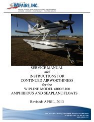
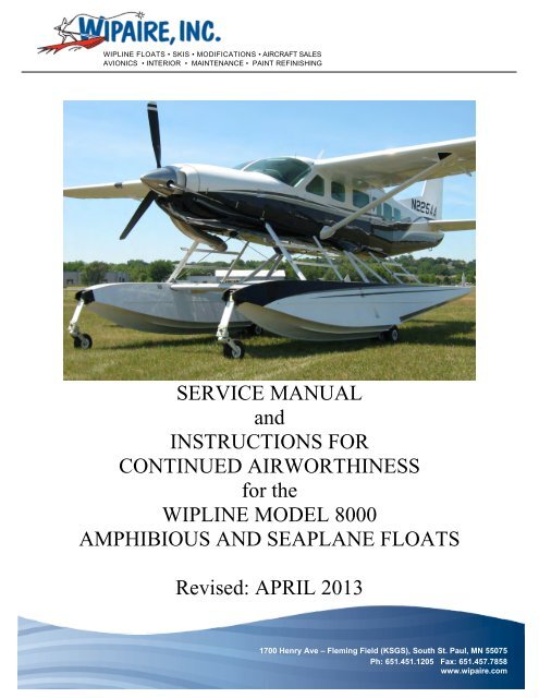
WIPLINE FLOATS • SKIS • MODIFICATIONS • AIRCRAFT SALESAVIONICS • INTERIOR • MAINTENANCE • PAINT REFINISHINGSERVICE MANUALandINSTRUCTIONS FORCONTINUED AIRWORTHINESSfor theWIPLINE MODEL <strong>8000</strong>AMPHIBIOUS AND SEAPLANE FLOATSRevised: APRIL 20131700 Henry Ave – Fleming Field (KSGS), South St. Paul, MN 55075Ph: 651.451.1205 Fax: 651.457.7858www.wipaire.com
WIPLINE MODEL <strong>8000</strong> SERVICE MANUALTHIS PAGE INTENTIONALLY LEFT BLANKPage 2 of 631002554 • Rev H
WIPLINE MODEL <strong>8000</strong> SERVICE MANUALTABLE OF CONTENTSSECTIONPAGELOG OF REVISIONS .................................................................................................................... 5NEW CUSTOMER INFORMATION .............................................................................................. 6WARRANTY CLAIM FORM .......................................................................................................... 71.0 GENERAL ............................................................................................................................. 122.0 FLOAT HULL MAINTENANCE ............................................................................................. 132.1 GENERAL ......................................................................................................................... 133.0 FLOAT HANDLING, JACKING, AND AIRCRAFT TOWING ................................................ 164.0 AMPHIBIAN LANDING GEAR SYSTEM OPERATION & MAINTENANCE .......................... 174.1 LANDING GEAR HANDLE ................................................................................................ 174.2 INDICATOR LIGHTS ......................................................................................................... 174.3 LANDING GEAR OPERATION ......................................................................................... 184.4 EMERGENCY PUMP HANDLE ........................................................................................ 185.0 MAIN AND NOSE GEAR OPERATION, REMOVAL AND SERVICE .................................. 195.1 DESCRIPTION AND OPERATION ................................................................................... 195.1.1 SERVICE – NOSE GEAR ........................................................................................... 205.1.2 SERVICE – MAIN WHEELS AND BRAKES ............................................................... 205.1.3 SERVICE – MAIN GEAR OLEO ................................................................................. 205.2 ADJUSTMENT/TEST ........................................................................................................ 225.2.1 NOSE GEAR .............................................................................................................. 225.2.2 NOSE BOX TRACK WEAR ........................................................................................ 225.2.3 SERVICE – MAIN GEAR RETRACTION SYSTEM .................................................... 225.2.4 BLEEDING HYDRAULIC SYSTEM AFTER SERVICE ............................................... 235.3 MAIN AND NOSE GEAR REMOVAL AND DISASSEMBLY ............................................. 245.3.1 REMOVAL OF MAIN GEAR OLEO ............................................................................ 245.3.2 REMOVAL OF MAIN GEAR RETRACTION CYLINDER............................................ 295.3.3 REMOVAL OF MAIN GEAR DRAG LINK ................................................................... 295.3.4 REMOVAL OF NOSE GEAR FROM NOSE BOX ...................................................... 295.3.5 REMOVAL OF NOSE GEAR BOX ............................................................................. 305.3.6 REMOVAL OF LOWER NOSE GEAR FROM PIVOT BLOCK ................................... 305.4 SERVICE SCHEDULE ...................................................................................................... 305.5 HYDRAULIC PUMP SYSTEM, DISASSEMBLY AND SERVICE ...................................... 335.6 INSPECTION TIME LIMITS AND CHECKLIST................................................................. 345.7 CESSNA FLOAT REMOVAL INSTRUCTIONS / PROCEDURES .................................... 381002554 • Rev H Page 3 of 63
WIPLINE MODEL <strong>8000</strong> SERVICE MANUAL5.8 CESSNA FLOAT RE-INSTLLATION INSTRUCTIONS / PROCEDURES ........................ 41FIGURE 5-1 SCHEMATIC HYDRAULIC SYSTEM .................................................................. 45FIGURE 5-2 SCHEMATIC ELECTRICAL SYSTEM ............................................................... 46FIGURE 5.3 ASSEMBLY MAIN GEAR RETRACTION SYSTEM ........................................... 47FIGURE 5.4 ASSEMBLY – MAIN GEAR SHOCK STRUT...................................................... 48FIGURE 5-5 ASSEMBLY MAIN GEAR AND BRAKE ............................................................. 49FIGURE 5-6 ASSEMBLY NOSE GEAR SYSTEM .................................................................. 505.9 WIEGHT AND BALANCE .................................................................................................. 515.9.1 WEIGHING PROCEDURES FOR CESSNA 208 CARAVAN ..................................... 516.0 WATER RUDDER RETRACTION AND STEERING SYSTEM............................................. 526.1 DESCRIPTION .................................................................................................................. 526.2 ADJUSTMENT .................................................................................................................. 526.3 SERVICE SCHEDULE ...................................................................................................... 527.0 REPAIRING FLOAT HULL SKINS, BULKHEADS AND SHEET METAL ............................. 53FIGURE 7-1 TYPICAL SKIN REPAIR ..................................................................................... 54FIGURE 7-2 TYPICAL SKIN REPAIR ..................................................................................... 55FIGURE 7-3 TYPICAL SKIN REPAIR ..................................................................................... 56FIGURE 7-4 TYPICAL REPAIR BOTTOM SKIN TO KEEL INSTRUCTIONS ........................ 57FIGURE 7-5 TYPICAL REPAIR BOTTOM SKIN TO KEEL INSTRUCTIONS. ....................... 58FIGURE 7-6 TYPICAL REPAIR BOTTOM SKIN TO KEEL (ALT) INSTRUCTIONS .............. 598.0 REPAIRING FLOAT HULL EXTRUSIONS ........................................................................... 60FIGURE 8-1 TYPICAL REPAIR SPLICE OF KEEL ................................................................ 61FIGURE 8-2 TYPICAL REPAIR SPLICE OF CHINE .............................................................. 62FIGURE 8-3 TYPICAL CAP SPLICE TO KEEL ...................................................................... 63Page 4 of 631002554 • Rev H
WIPLINE MODEL <strong>8000</strong> SERVICE MANUALLOG OF REVISIONSREV PAGES DESCRIPTION DATEA 3 Revised Aircraft jacking position 3-16-05B 12,18C 7, 12D 19-22EFGH9,10,15,1629,36465,6,12,1321ALLAdded greasing zerk to tasks and changeddrawingAdded an inspection time limit and tolerances for theNose Block Track wear.Made several additions to the inspectionchecklist.Changes to the Cleaning, Corrosion and Maingear lubrication procedures and additional minorchanges to the inspection checklist.9-28-054-18-061-18-075-31-08Changed water rudder cable tensions. 8-15-08Changed main gear oleo servicing information.Added enhanced customer information pagesand cleaning and corrosion pages.Reformat of entire document, Add green greaseas approved grease, update to float procedureswith clarification on rear door support cables.7-15-094/18/20131002554 • Rev H Page 5 of 63
WIPLINE MODEL <strong>8000</strong> SERVICE MANUALNEW CUSTOMER INFORMATIONCustomer NameBilling AddressShipping AddressPhone NumberFax NumberPurchasing ContactPhone NumberE-MailFax NumberAccounts Payable ContactPhone NumberE-MailFax NumberType(s) of Aircraft Owned or Maintained<strong>Model</strong>(s) of Floats and Skis Owned or MaintainedFedEx and/or UPS account number (if applicable)Please return to <strong>Wipaire</strong> Customer <strong>Service</strong>:Fax 651-306-0666 Phone 651-306-0459 Customer<strong>Service</strong>@wipaire.comPage 6 of 631002554 • Rev H
WIPLINE MODEL <strong>8000</strong> SERVICE MANUALWARRANTY CLAIM FORMAircraft Owner Name:Address:City, State, Zip:Phone:Fax:E-Mail Address:Aircraft InformationAircraft <strong>Model</strong> Number:Aircraft Registration ID:Aircraft Serial Number:Please circle the category that most describes the aircraft’s primary type of operations:Commercial Operator Training/Rental Private Use Business UseFloat / Ski InformationFloat / Ski <strong>Model</strong>:Float / Ski Serial Numbers:Total Hours on Floats / Skis to Date:Approximate Hours per Year of Use:Date Floats / Skis Went Into <strong>Service</strong> (New):Claim InformationDate of Claim:Faulty Part Nomenclature and Number:Company Performing Maintenance:Work Order Number:Phone:Contact Person:Fax:E-Mail Address:<strong>Wipaire</strong> Representative and any RMA or Claim Numbers:Please include a brief description of the conditions at the time of failure or damage, if applicable, and anyadditional remarks:Please fax or mail back to us. If you prefer, you can e-mail the form to Customer<strong>Service</strong>@wipaire.com.1002554 • Rev H Page 7 of 63
WIPLINE MODEL <strong>8000</strong> SERVICE MANUALTHIS PAGE INTENTIONALLY LEFT BLANKPage 8 of 631002554 • Rev H
WIPLINE MODEL <strong>8000</strong> SERVICE MANUAL1002554 • Rev H Page 9 of 63
WIPLINE MODEL <strong>8000</strong> SERVICE MANUALTHIS PAGE INTENTIONALLY LEFT BLANKPage 10 of 631002554 • Rev H
WIPLINE MODEL <strong>8000</strong> SERVICE MANUALINTRODUCTIONThis manual describes the general servicing and maintenance for the <strong>Model</strong><strong>8000</strong> float, including hull and landing gear. For services and repairs not covered by thismanual contact the factory.The service products referred to throughout this manual are described by theirtrade name and may be purchased from the factory Parts Department.To contact <strong>Wipaire</strong> for service assistance or parts sales, call or write:<strong>Wipaire</strong>, <strong>Inc</strong>.1700 Henry Avenue – Fleming FieldSouth St. Paul, MN 55075Telephone: (651) 451-1205Fax: (651) 451-1786Website: www.wipaire.comEmail: customerservice@wipaire.com1002554 • Rev H Page 11 of 63
WIPLINE MODEL <strong>8000</strong> SERVICE MANUAL1.0 GENERALThe model <strong>8000</strong> seaplane or amphibious float is an all aluminum constructedfloat with watertight compartments. The actual displacement in fresh water for eachfloat is 8108 pounds buoyancy for the seaplane and 7922 pounds buoyancy for theamphibian. The amphibian float is geometrically the same as the seaplane except forthe addition of landing gear and internal structure for the gear.The water rudder system is cable operated with ball bearing pulleys. Waterrudder cables tie into the existing aircraft rudder system.The main landing gear has dual 600 x 6 8-ply tires and the nose landing gearhas one 500 x 5 10-ply tire. The gear system is hydraulically actuated and driven bytwo hydraulic pumps. Brakes are hydraulic and have a caliper on each main wheel fora total of four brakes.Steering on land is accomplished by differential braking. The nose wheels arefull castering.Access to the float interior is accomplished by removing covers on the top deckand sixcovers inside the wheel well. When necessary, water inside the float hulls maybe removed through pump out cups located on the outboard edge of each float topskin.Page 12 of 631002554 • Rev H
WIPLINE MODEL <strong>8000</strong> SERVICE MANUAL2.0 FLOAT HULL MAINTENANCE2.1 GENERALThe float structure is manufactured entirely of 6061-T6 corrosion resistantaluminum sheet and extrusions. Skins on the inside are primed with a 3MSCOTCHWELD primer after being cleaned and acid-etched. Exterior surfaces arecleaned and alodined. Surfaces are then primed with an epoxy-based primer andfinished with enamel color paint.Hard Landing and Damage InvestigationAfter a thorough cleaning of the suspected damaged area, all structural parts shouldbe carefully examined to determine the extent of damage. Frequently the forcecausing the initial damage is transmitted from one member to the next causingstrains and distortions. Abnormal stresses incurred by shock or impact forces on arib, bulkhead or similar structure may be transmitted to the extremity of the structuralmember, resulting in secondary damage, such as sheared or stretched rivets,elongated bolt holes or canned skins or bulkheads. Points of attachment should beexamined carefully for distortion and security of fastenings in the primary andsecondary damaged areas at locations beyond the local damage. Inspect aircrafttubes in area of float fitting attach for sign of bending, cracked welds, or any othersigns of damage.1002554 • Rev H Page 13 of 63
WIPLINE MODEL <strong>8000</strong> SERVICE MANUALCleaningThe outside of the float should be kept clean by washing with soap and water.Special care should be taken to remove engine exhaust trails, waterline marks, andbarnacle deposits. After saltwater operation, washing with fresh water should bedone daily with special attention to hard-to-reach places such as: seams, wheelwell, etc.Alternatively, water taxiing in FRESH WATER at step-speed can help to flush theentire system.OPERATORS IN SALTWATER ARESTRONGLY CAUTIONED – RINSING THE ENTIREAIRCRAFT & FLOATS WITH FRESH WATERAT THE END OF EACH DAY OR PERIODICALLYIS CRITICAL. FAILING IN THIS CLEANING CAN SEVERLYSHORTEN THE LIFE OF THE FLOATS.The float interior should be flushed if salt water enters the compartments. If thefloats are being stored inside, remove inspection covers so the interior will dry out.THE ABOVE CLEANING TECHNIQUES ARE VITALFOR KEEPING CORROSION TO A MINIMUM. SALTWATEROPERATIONS AND ENVIRNMENT ARE STRONGLY LINKED TOCORROSION AND MUST BE ADDRESSED PROACTIVELY.Page 14 of 631002554 • Rev H
WIPLINE MODEL <strong>8000</strong> SERVICE MANUALCorrosionCorrosion is a reaction that destroys metal by an electrochemical action that convertsmetal to oxide. Corrosion is accelerated when in contact with dissimilar metals such asaluminum and steel, or any material that absorbs moisture like wood, rubber, or dirt .After removing the corroded area, restore area to original finish (prime and enamel).BOESHIELD T9 or ACF-50 may also be applied to stop corrosion. Refer tomanufacturer’s instructions for application instructions.Maintaining the float inside and outside finishes by washing after saltwater operationswill help protect the float from corrosion. Periodically all hardware should be coveredwith a waterproof grease or Paralketone. Under saltwater conditions, bolts should beremoved at least once a year and grease reapplied to the shafts, heads and nuts.THE ABOVE CLEANING TECHNIQUES ARE VITALFOR KEEPING CORROSION TO A MINIMUM. SALTWATEROPERATIONS AND ENVIRNMENT ARE STRONGLY LINKED TOCORROSION AND MUST BE ADDRESSED PROACTIVELY.1002554 • Rev H Page 15 of 63
WIPLINE MODEL <strong>8000</strong> SERVICE MANUAL3.0 FLOAT HANDLING, JACKING, AND AIRCRAFT TOWINGTo jack the floats for servicing tires,brakes, or doing retraction tests, it isrecommended that a floor type jack (oneton minimum.) be used. These jacks arecommonly used for auto repair. The jackshould be positioned on the keelcenterline on the first bulkhead forward ofthe step. Example is shown to the left ofthis text. The jack should contact the keelsquarely and if room permits, slip a boardbetween the jack and keel. Raise thefloat slowly; making sure the aircraftstays balanced. After raising, block upthe keel in several places and lower thejack. Raise only one float at a time withthe opposite float landing wheelschocked. Position a sawhorse undermain and after body keel to keep aircraftfrom tipping fore and aft.For raising the aircraft for float installation and removal, use the lifting rings ifprovided or lift at front wing attach points. Aircraft may be lifted by spreader bars with alaunching dolly. WITH CAUTION lift on both spreader bars as close to float hull aspossible.When towing the amphibian aircraft, tow lugs are provided on the lower forwardside of the nose spring. A rigid “V” frame can be fabricated to attach to these lugs andaircraft towed with a tractor. <strong>Wipaire</strong> Parts has this tow bar available.A lifting apparatus that will pick the aircraft up by the lifting rings at wing attachpoints from a ceiling hoist, to be fabricated. Contact factory for details if necessary.Page 16 of 631002554 • Rev H
WIPLINE MODEL <strong>8000</strong> SERVICE MANUAL4.0 AMPHIBIAN LANDING GEAR SYSTEM OPERATION & MAINTENANCEThe landing gear incorporated within the amphibious floats on this airplane isretractable, quadricycle type with two swiveling nose (or bow) wheels and four (4) (two(2) sets of dual) main wheels. Air-oil shock struts on the two main landing gearassemblies provide shock absorption.The main landing gear has dual 6:00 x 6 8-ply type III tires and the nose landinggear has one 5:00 x 5 10-ply tire. The gear system is hydraulically actuated anddriven by two hydraulic pumps. Brakes are hydraulic and have a caliper on each mainwheel.Steering on land is accomplished by differential braking. The nose wheels are fullcastering.Landing gear extension and retraction is accomplished by two (2) electricallydrivenhydraulic pumps and four (4) hydraulic actuators (one (1) for each gear). Thehydraulic pumps are located in fuselage aft of cockpit and the hydraulic actuators arelocated adjacent to each gear. Hydraulic system fluid level should be checkedperiodically by viewing the sight glass for fluid level in the upper one-third of the range.If fluid is low, fill with MIL-H-5606 or equivalent. Filters are installed on pickup tubeinside of hydraulic reservoirs. Clean every 100 hours.Landing gear operation is initiated by movement of the landing gear handle.When the handle is repositioned, hydraulic pressure in the system will drop andpressure switches will automatically turn on the hydraulic pump motors to maintainoperating pressure in the system. When the gear cycle is completed, the pump willautomatically shut off. If the pressure in the system drops to a preset value, thepressure switches turn the pump motors back on and build up the pressure to the limitagain. Eight (8) position-indicator lights four (4) gear UP and four (4) gear DOWN areprovided to show landing gear position. Two (2) additional indicator lights show whenthe landing gear pump motors are operating.4.1 LANDING GEAR HANDLEThe landing gear handle controls a hydraulic selector valve within the selectorhead in the instrument panel and has two (2) positions (UP and DOWN LAND) whichgive a mechanical indication of the gear position selected. From either position, thehandle must be pulled out to clear a detent before it can be repositioned.4.2 INDICATOR LIGHTSTen (10) indicator lights are mounted on the landing gear control unit adjacent tothe landing gear handle. Four (4) blue indicator lights, labeled NOSE and MAIN (lefthandlights for the left float and right-hand lights for the right float), show by theirillumination that the landing gear is up and locked. The four (4) amber indicator lights,labeled NOSE and MAIN (left-hand lights for the let float and right-hand lights1002554 • Rev H Page 17 of 63
WIPLINE MODEL <strong>8000</strong> SERVICE MANUALfor the right float), are illuminated when the landing gear is down and locked. Neitherset of lights is illuminated when the landing gear is in transit. Two (2) red indicatorlights, labeled PUMP ON 1 and 2 illuminate when current is supplied to the landing gearmotors. If the motors continue running during flight or on and off repeatedly, the motorsshould be shut off by pulling AMPHIBIAN PUMP 1 AND AMPHIBIAN PUMP 2 circuitbreakers, since continual running of the motors can result in premature motor failure.Prior to landing, the circuit breakers should be pushed in to reactivate the circuits.Troubleshoot hydraulic problem per section 5.4.4.3 LANDING GEAR OPERATIONTo retract or extend the landing gear, pull out on the landing gear handle and moveit to the desired position. When the handle is positioned, pressure on the hydraulicsystem reduces to where the hydraulic motors automatically turn on. The motors powerthe hydraulic pumps and actuate the gear actuator for each gear. During operation ofthe landing gear motors the PUMP ON 1 and 2 indicator lights are illuminated. Whenthe gear cycle is completed, pressure builds up in the hydraulic system andautomatically shuts off the hydraulic motors. Each gear operates independently of theother, and therefore, the position lights illuminate at various times.4.4 EMERGENCY PUMP HANDLEAn emergency hand pump is located on the floor between the front seats in theevent the normal hydraulic system fails. This hand pump may be used to retract orextend the land gear. To actuate the hand pump, pull out the handle. Prior to utilizingthe emergency hand pump, pull the AMPHIB PUMP 1 and 2 circuit breakers todeactivate the electric hydraulic pumps. Select UP and DOWN using the normallanding gear selector handle. Place the emergency hand pump handle in the pump andpump up and down. When a gear reaches the selected position, its indicator light willilluminate. After all four (4) gears are in the selected position there is a noted increasein resistance of hand pump operation.Page 18 of 631002554 • Rev H
WIPLINE MODEL <strong>8000</strong> SERVICE MANUAL5.0 MAIN AND NOSE GEAR OPERATION, REMOVAL AND SERVICE5.1 DESCRIPTION AND OPERATIONRetraction and extension of the main and nose landing gear is effected by a hydraulicactuation system shown schematically in figure 5.3.The gear system is hydraulically actuated and driven by two hydraulic pumpslocated in the Aft fuselage.A pressure of between 500 and 1000 psi is maintained in the supply line. Whenthe pressure falls below 500 psi, the pressure switch activates the pump solenoid,providing power to the pump. When the pressure reaches 1000 psi, the pressureswitch deactivates the solenoid and the pump motor stops. Figure 5.2 shows theelectrical schematic of the system. A check valve on the output side of the pumpretains pressure in the system while the pump is off. The pump has an internal reliefvalve, which directs oil back to the pump reservoir when the line pressure exceeds1200 psi. The system also has an internal relief valve to protect against thermalexpansion when line pressure exceeds 1900 psi.A cockpit mounted control valve accomplishes the selection of gear up or geardown. Each float gear has individual indicator lights on the control valve allowing thepilot to confirm that each gear has fully retracted or extended.An emergency hand pump is provided, in case of total electric pump failure, or loss offluid. The reservoir has additional hydraulic fluid, available only to the hand pump.The main gear is mechanically locked in both up and down positions. Locking andunlocking is done utilizing a small amount of lost motion of the actuator rod. Retractiontakes place when pressure is exerted on the actuator piston driving the collar along theslide tube. The lock is tripped when the follower slides up the contoured track in theactuator as shown in figure 5.3. A reverse process affects extension. Gear positionlight proximity switches are closed when the appropriate hook (containing the magneticmaterial) nests over the locking bar.Shock absorption for the main landing gear is provided by a hydraulically dampened airspring. Figure 5.4 shows the main components. The oil and air share a commonchamber. When the oleo is collapsed, the oil is forced through the main orifice,compressing the air in the upper cylinder. Extension reverses this process. Theextended oleo is initially set at the factory to 210 psi no load. In-field adjustment of airpressure and oil volume is described in this section.The nose gear has an over-center down lock. Retraction occurs when pressure isapplied to the forward face of the actuator piston and the carriage is drawn along thetracks in the nose box as shown in figure 5.6. Gear position light proximity switches1002554 • Rev H Page 19 of 63
WIPLINE MODEL <strong>8000</strong> SERVICE MANUALare closed when the piston containing the magnetic material has reached either end ofits travel.The nose gear consists of composite fiberglass beams that are attached at the bottomto castering blocks. Inside the block is a castering pin that is set into the machined forkassembly. The castering pin allows the nose wheel to pivot in a complete circle. Thegeometry is such that no shimmy dampers are necessary. A spring loaded cam rides in agroove machined in the castering pin. This groove as a flat surface on the back face withthe result that the cam provides retention of the pin the block and self-centering of thewheel.5.1.1 SERVICE – NOSE GEARThe nose gear pivot assembly should be cleaned and inspected every 25 hours ormore frequently whenever in water for extended period of time, especially saltwater.Nose gear tracks that are the older style gold track and white block are to be lightlygreased. Apply grease to a cloth on a stick or rod and run along tracks inside of thenose box, both sides. Newer track and block that are black should be cleaned and leftdry or alternately cleaned and wiped with a rag with dry silicone spray on it.The nose wheels contain grease nipples for the wheel bearings. They should begreased every 25 hours.Nose tires are standard 5:00 x 5, 10-ply, inflated to 60 +/- 5 psi.5.1.2 SERVICE – MAIN WHEELS AND BRAKESGrease nipples are provided on all wheels and bearings and should be greased every25 hours or after an extended period of time in the water. Water/heat resistant greaseis recommended and it is important as with any aircraft operations not to mix types ofproducts.The dual piston brakes need no special care other than to maintain the brake disc freeof rust, which causes premature brake lining wear. Bleeding is carried out in the usualmanner from the bottom up.Main wheel tires are standard 6:00 x 6, 8-ply type III aircraft tires, inflated to 45 +/- 5 psi.(Refer to figure 5-5)5.1.3 SERVICE – MAIN GEAR OLEOOIL LEVEL - The correct level is best set by draining and refilling with the correctquantity of fluid (1140 ml). This should be done with the oleo removed from the float,which process is outlined in Section 5.2. CAUTION: Release air pressure and removeair valve before attempting to service oleo. After filling, refit valve and cap, thenpressurize to 210 psi. (Note: Use only MIL-H-5606 hydraulic fluid.)Page 20 of 631002554 • Rev H
WIPLINE MODEL <strong>8000</strong> SERVICE MANUALAIR PRESSURE – The correct air pressure is 210 psi (+/-10 psi) on a fully extendedoleo (no load) or it can be inflated to approximately 5-6 inches on an unloaded aircraftwhile sitting static on level ground.SEALS – Seals should be replaced whenever the oleo is disassembled or leaking.CAUTION: Release air pressure and remove air valve before attempting todisassemble oleo. The seals are standard “O” rings or T-seals whose part numbers aredepicted in figure 5.41002554 • Rev H Page 21 of 63
WIPLINE MODEL <strong>8000</strong> SERVICE MANUAL5.2 ADJUSTMENT/TEST5.2.1 NOSE GEARAdjustment of actuator stroke is provided at the ends of the piston rods.The length of the nose gear rod is adjusted such that the over-center knuckle (brass)rollers just bottom out on the down side and the piston just bottoms out on the mountingflange.The up stops nests in the up-stop pin. See figure 5.6 for location and assembly.Nose gear proximity switches are located on clips that are mounted on the outercylinder body, one on each end. The most forward switch is for the gear down lightsand most aft is for the gear up position lights. Set the proximity switch mounting clipalong outer cylinder body to a position such that the light goes out when the over-centertrack is about ¼ inch from bottomed position while traveling in the up direction. Lightsshould come on about 1/8 inch from the bottomed position while traveling in the downdirection.The cylinder piston has a magnet that will activate the proximity switches.5.2.2 NOSE BOX TRACK WEARDue the wear over time the roller/slide block places on the track as the gear areretracted, the block needs to be measured for the amount of wear. The tolerance forwear is .050 inches. If the wear is, or is less than the limit, it can still be used. If the wearin the track is greater than .050 inches, the block must be replaced. This check is to bedone every 200 hours and is part of the maintenance checklist.On the <strong>8000</strong> Series Floats Gear Track P/N 8A07337 (-003 LT -004 RT)5.2.3 SERVICE – MAIN GEAR RETRACTION SYSTEMAs explained in Section 5.0, retraction involves the main gear carriage moving back andforth along the slide tube. The locking mechanism also moves a small amount inservice, enabling the locking hooks to hook and release as the gear locks in the up ordown position. Consequently, the slide tube and the main gear ram must stay lubricateddespite varying operating circumstances in order to work as intended.Greasing might not be necessary, depending on operations, but these areas should beinspected visually at least every 25 hours for cleanliness and lubrication.The slide tube, gear locking ram and main carriage can be accessed at various points ofoperation via the top deck panels or via the main wheel well with the tire off.Recommended grease is HCF Grease, P/N 605 available from our parts department.Care should be taken as with all aviation maintenance not to mix different types ofgreases, especially in critical areas like this. Grease needs to be applied directly alongPage 22 of 631002554 • Rev H
WIPLINE MODEL <strong>8000</strong> SERVICE MANUALthe length of the slide tube shaft and locking ram in addition to using a grease gun forthe zerk on the main carriage. Grease should be pumped several times past the point atwhich it comes out the front of the carriage so it can migrate all the way thru the systemto the locking hooks. Also, LPS 2 should be applied to the locking hooks while their topcover is removed.The main gear actuator cylinder is not adjustable. These are pre-set at the factory toensure that the main gear is locked at the end of each stroke and that correct indicationis given on the cockpit console. The up and down lock may be adjusted so the lock isfully engaged by adjusting the set screws shown in figure 5.3. Loosen the jamb nutadjust and tighten jamb nut.The main gear proximity switches are located on each end of the gear stroke. Theforward switch is located on the forward side of the gear tunnel. It is accessible throughthe top deck access cover. The aft proximity switch is located on the float bulkhead justaft of the wheel well, accessible though the float top deck cover.The main gear proximity switches are adjusted loosening the mounting screws andpositioning them as such that the light goes out when the lock hook is raised about 1/8inch off its nested position and comes on again upon nesting.5.2.4 BLEEDING HYDRAULIC SYSTEM AFTER SERVICEThe system automatically bleeds, provided sufficient oil is maintained in the reservoir.To check the fluid level, fill the reservoir with hydraulic oil and cycle the gear. The fluidlevel should be maintained in the upper one third (1/3) of the sight glass. If the reservoirempties (i.e. fluid disappears in sight glass) stop the cycle by pulling the circuit breakeron the control panel. Fill the reservoir again and complete the cycle. Continue thisprocedure until the fluid level in the reservoir stabilizes (it will vary in level between upand down positions). If the fluid level continues to decline during gear cycles, check forexternal leaks.1002554 • Rev H Page 23 of 63
WIPLINE MODEL <strong>8000</strong> SERVICE MANUAL5.3 MAIN AND NOSE GEAR REMOVAL AND DISASSEMBLY5.3.1 REMOVAL OF MAIN GEAR OLEOJack the aircraft by method described in section 3. With the main wheels off the ground(both sides), run the gear up so the main carriages are approximately 2 inches forwardof down-lock position. This must be accomplished to remove the top oleo bolt. In orderto remove the lower bolt, remove the wheel on the head side of the bolt.Shock Strut ServicingNOTE: RELEASE PRESSURE IN STRUT BEFORE DISASSEMBLY!!1) Disassemble the strut, removing both end caps. Take apart the gland section andmetering pin so the parts can be easily inspected for wear and replacement partscan installed as needed.2) Inspect all parts carefully after cleaning for wear and scoring, especially the piston,gland section, and the inside of the outer cylinder. Also make sure to check thebushings in the end-caps for wear and security.3) The metering tube does not need to be taken apart from the end-cap of the insidecylinder unless extensive cleaning is desired. If it is disassembled:a) To return the metering tube height and condition to factory preset, first apply blueLock-Tite to the threads of the inner end-cap threads that hold the metering pinfor added security until next removalPage 24 of 631002554 • Rev H
WIPLINE MODEL <strong>8000</strong> SERVICE MANUALb) The metering pin is threaded until the measurement from the floor of the inside ofthe end-cap to the end of the inserted metering tube is 12.037 inches if the newT-seals are being used and 11.937 inches if the old style O-rings are used.c) Tighten the associated jam nut at that end and stake it for added security.d) Set this metering tube assembly aside and move on to next steps.4) On the other end, install the metering pin with Lock-Tite onto the end-capand tighten to approx. 30 ft./lbs.5) Install outer T-seal to end-cap with Vaseline. Also lube the inside of the outercylinder where the end-cap seats for ease of assembly.NOTE: Use Vaseline or equivalent as it dissolves in hydraulic fluid.1002554 • Rev H Page 25 of 63
WIPLINE MODEL <strong>8000</strong> SERVICE MANUAL6) Install the end-cap bolts with gasket sealer on the threads for added security.Tighten to 25-30 in./lbs. making sure not to over-tighten, damaging the T-seal. Setthis part of the unit aside and move on to next steps.7) To assemble the gland assembly, insert the inside T-seal and wiper, againusing Vaseline on the T-seal.a. The gland must be installed from the end-cap side (this is the side withoutthe holes).b. Lube the outside of the inner cylinder with hydraulic fluid for ease ofassembly.c. Install the T-seal into the end-cap, again using Vaseline for lube.d. Install the inner cylinder into the end-cap (the end of the tube withoutholes).Page 26 of 631002554 • Rev H
WIPLINE MODEL <strong>8000</strong> SERVICE MANUAL7) For piston install, place the piston onto the metering tube using hydraulic fluid forlube to prevent damage to the threads.a. Using a spanner wrench, tighten the piston to the inner cylinder.b. Install the jam nut onto the piston end of the metering tube and stake forsecurity.c. Install the 2 T-seals onto the exterior of the piston and gland, and lubewith Vaseline.8) Gently clamp the outer tube end in a vise and add 1140 ml of hyd. fluid (5606 orequivalent).9) Lube the inside of the outer cylinder where the gland and the piston will rest.10) Install the inner cylinder into the outer assembly, making sure that the gland isseated against the piston.1002554 • Rev H Page 27 of 63
WIPLINE MODEL <strong>8000</strong> SERVICE MANUAL12) Re-install the center bolts using gasket sealer.13) Install the O-ring onto the fill/drain plug before installing the plug onto the endcapand tighten.14) Install the O-ring onto the Schraider valve and install onto the outside of the endcap.NOTE: Align Schraider valve 180 degrees from the Placard.NOTE: Double check the plugs and bolts for properInstallation and security before adding gas charge.Page 28 of 631002554 • Rev H
WIPLINE MODEL <strong>8000</strong> SERVICE MANUAL15) Fill the strut with nitrogen to 210 psi +/_ 10 psi and close the valve and cap.5.3.2 REMOVAL OF MAIN GEAR RETRACTION CYLINDERRelieve pressure in system, place gear selector handle in neutral position (leverbetween up and down), and remove hydraulic lines. Remove end cap from end ofcylinder. Drain fluid. Remove forward end of cylinder from bulkhead flange. Removecylinder support ring from bulkhead. NOTE: Piston to be in the up position for cylinderremoval. Remove cylinder from piston and up through top float inspection cover. Toremove piston, remove top inspection cover on top forward end of gear tunnel,accessible from top float inspection cover forward of step. Pull back piston to exposetop of carriage in center of access cover. Remove .25 dia. retention bolt. Removepiston by pulling aft. See figure 5.3 for part breakdown.5.3.3 REMOVAL OF MAIN GEAR DRAG LINKRemove drag link from trunnions on step bulkhead. Axle is heat shrunk to drag linkand is not removable.5.3.4 REMOVAL OF NOSE GEAR FROM NOSE BOXGear must be in down position. Relieve pressure in system, place gear selectorhandle in neutral position (lever between up and down), and remove rear hydraulic line.Remove (4) bolts on forward end of cylinder. Drain fluid. Pull aft to expose internalpiston rod. Loosen jamb nut on forward side of cylinder ram at rod end. Turn pistonfrom aft side of nose box out of rod end. Lift up on gear assembly to unlock. Slide outof nose box. Note: On installation adjust piston so it bottoms out on aft flange whennose gear is in locked position. Also note orientation of trolley blocks. The side with themost edge distance from hole is to go toward each other on inside of trolley. (See figure5.6 for details).1002554 • Rev H Page 29 of 63
WIPLINE MODEL <strong>8000</strong> SERVICE MANUALMetal PartsFor security of attachment, cracks, metal distortion, broken welds, corrosion,condition of paint, and any other apparent damage.WiringFor security, chafing, burning, defective insulation, loose or broken terminals,corroded terminals.Bolts in Critical AreaFor corrosion, correct torque when installed, or when visual inspection indicates a needfor a torque check.Torque LimitsNut-In-lbsBolt SizeMin. Max.8-36 12 1510-32 20 251/4-28 50 705/16-24 100 1403/8-24 160 1907/16-20 450 5001/2-20 480 6909/16-18 800 1,0005/8-18 1,100 1,3003/4-16 2,300 2,5007/8-14 2,500 3,0001-14 3,700 4,5001 1/8-12 5,000 7,0001 1/4-12 9,000 11,000Some additional general maintenance areas are as follows:Nose and Main Gear TracksClean and lubricate with a dry teflon coating spray.JointsSpray all joints with light penetrating oil such as LPS 3 to ensure lubrication at alltimes.Electrical ConnectionsApply SP-400 SOFT SEAL or LPS 500 to all electrical connections to preventcorrosion.Hydraulic FluidFor use in all hydraulic systems, including brakes: MIL-H-5606.Page 32 of 631002554 • Rev H
WIPLINE MODEL <strong>8000</strong> SERVICE MANUAL5.5 HYDRAULIC PUMP SYSTEM, DISASSEMBLY AND SERVICEThe hydraulic pump is factory preset to the following pressures:Pressures switch operates below 500 psi and shuts off at 1000 psi.The pump also has an internal relief valve that opens at 1200 psi and a thermalrelief valve that opens at 1900 psi. These pressures are set with factory testequipment and are recommended to be sent back for overhaul or repair.The unit may be disassembled for cleaning.1. Relieve the pressure in the hydraulic system by placing the gear selector handlein the neutral position.2. On the forward lower side of the reservoir, remove drain plug to drain most ofthe hydraulic fluid.3. Remove the (4) screws on each tank (2) on upper side of the reservoir4. Dump out remaining oil, and clean reservoir.5. Unscrew stand pipe with the filter attached.6. Clean filter.7. If filter is removed from stand pipe, a new filter should be used.8. Reinstall tank and install seals to top of reservoir before installing on pump.9. Install drain plug and fill with clean MIL-H-5606 hydraulic fluid through thebreather pipe.10. Fluid level should be in the upper 2/3 of the sight gauge1002554 • Rev H Page 33 of 63
WIPLINE MODEL <strong>8000</strong> SERVICE MANUAL5.6 INSPECTION TIME LIMITS AND CHECKLISTINSTRUCTIONS/PROCEEDURES HOURLY LIMITS MECHANIC INSP.General Details 25 50 100 200 Annual Right LeftGeneralWash aircraft and floats with fresh waterand inspect surfaces, hardware and strutconnections for corrosion.If the airplane is exposed to salt- orpolluted water, the chances forcorrosion increase dramatically.Daily basic cleaning is essential.Check installed placards against the AFMor POH, and installation drawings. X XXormoreoftenXHulls &StrutsFloat InstallationBoarding steps: disassemble as neededand grease the step slide tubes.Disassemble and grease the flying wireclevis bolts/pins.Float exterior - inspect for damage,wrinkled metal, corrosion, paintloss, etc.If the floats are installed, removethe center section fairings foraccess. Struts and attach fittings:clean upper attach fittings and dogbone saddle area. If off aircraft, regreasebolts and return.Spreader Bars: inspect for loosescrews and cracks & seal betweenfairing and side skin. Insp. fairingsfor cracking and loose screws.X XX XXFloatInteriorsFloat structure (interior): pull up baggagefloors and inspect bulkheads.On the aircraft and floats: re-coatexposed hardware with suitablecoating for corrosion protection.Closely inspect for wrinkled metal &cracked flanges; watch closely bulkheads 9-21.X XX XBaggage compartment covers and seals -inspect for condition, security, operation,excessive wear and corrosion undernutplates.After hardware inspection, coatwith anti-corrosion grease toprotect.X XPumper Tube Installation - inspect forcondition, security, routing of hoses. X XPage 34 of 63 1002554 • Rev H
WIPLINE MODEL <strong>8000</strong> SERVICE MANUALINSTRUCTIONS/PROCEEDURES HOURLY LIMITS MECHANIC INSP.General Details 25 50 100 200 Annual Right LeftWaterRudderSystem& TailElectricalSystemWater rudder boots - inspect for cuts,tears, and conditionWater rudder steering and retractsystems - inspect the following: cables forbroken wire; fittings for cable slippage,cracks and distortion; cable pulleys forfreedom of rotation and cable guard pinsfor presence; riggingOn the aircraft: remove clean, inspect andgrease the aux. finlets on the horizontalstabilizer.Pump and indicator light wiring - inspectfor chafing, broken or loose terminals andgeneral condition.Solenoids - inspect wiring, mounting andgeneral condition.Water rudder blades and posts -inspect for damage, security ofattachment, corrosion, paint,rigging. Check post bolts andbushings and lube with LPS 2.Check top and bottom rollers forrotation and lube with LPS 2 orsimilar product.Tension cables to30 lbs. +/- 5X XX XXX XX XPressure Switches - inspect wiring,mounting and general condition.X XPump Motors - inspect wiring, mountingand general condition. X XLandingGearSystemsInspection and servicing nose geartracks:Nose gear box/block tracksmeasured at slide route for wear,.050 inches or less wear toleranceGold and white track and blockclean and use grease. Black trackand block – clean and dry or cleanand wipe with silicone spray.Check side play – 3/32 to 1/16inches max tolerance.X XXX1002554 • Rev H Page 35 of 63
WIPLINE MODEL <strong>8000</strong> SERVICE MANUALINSTRUCTIONS/PROCEEDURES HOURLY LIMITS MECHANIC INSP.General Details 25 50 100 200 Annual Right LeftNose gear pivot blocks and forks - inspectfor condition, lubrication, corrosion, paint. X XNose & main wheel bearing - grease Zerks X XInsp. Main gear slide tube, ram and lockinghooks for lubrication. Lube carriage zerkliberally.Grease with HCF p/n 605.Spray locking hooks form thetop with LPS 2 to penetrate.Hydraulic fluid level: Mil-H-5606 X XWheels and tire - inspect for wear, pressure,condition (45lbs +/_ 5lbs) X XBrake assemblies - inspect for wear,corrosion, leakage X XHydraulic fluid screen - clean and inspect.NOTE: If floats sit for extended periods oftime (I.e. If removed during winter months),screen should be cleaned before puttingfloats back into service. Hydraulic fluid inX Xreservoir should be checked for moisture orother contaminates and changed ifnecessary.Insp. FWD slide tube mounting bolt forcorrosion and wear when the gear are out.Clean and lube the slide tube beforeXreturning.Main and Nose gear actuator, assemblies -inspect for condition, lubrication, leakage,corrosion, and cleanliness.With gear out: Inspect FWD slide tubeX Xmounting bolt for corrosion and wear. Clean& grease FWD slide tube.Nose gear springs - scotchply springs,inspect for cracks, delamination and paint.X XMain gear drag link garlock bushings -inspect for condition, lubrication, andcorrosion.X XXPage 36 of 63 1002554 • Rev H
WIPLINE MODEL <strong>8000</strong> SERVICE MANUALINSTRUCTIONS/PROCEEDURES HOURLY LIMITS MECHANIC INSP.25 50 100 200 Annual Right LeftClean the wheel wells to facilitate generalcondition inspection.Main gear oleos - inspect for evidence ofleakage, proper extension, check cylinder forcorrosion, pitting, cleanliness and securityHydraulic lines and fittings - inspect for leaks,condition and security.Hydraulic Manifolds (if equipped) - inspect forcondition, security, and leaks.X XX XRefer to section 5.2 X XX XBrake system plumbing - inspect for leaks,condition and security.Main gear oleos – Check for staticcompression, leaks and proper pressure. Theoleo should be fully serviced or replaced withoverhauled as required.Perform retraction test:If full servicing is required, use5606 hydraulic fluid & NitrogenRefer to section 5.2Inspect main gear up and downlock hooks for properengagement.Inspect nose gear trolley forproper travel.Inspect nose gear for excessiveplay in the down positionX XX XX XX XX XPerform emergency gearextension & retractionXXNose and main wheel bearings - disassembleand inspectRe-grease bearings withrecommended water resistantgreaseX X1002554 • Rev H Page 37 of 63
WIPLINE MODEL <strong>8000</strong> SERVICE MANUAL(CONT.) CESSNA 208 FLOAT REMOVAL INSTRUCTIONS/PROCEEDURESTHIS IS INTENDED AS A GENERAL GUIDE. EACH INSTALLATION MAY HAVESUBTLE DIFFERENCES. ALWAYS USE THE INSTALLATION DRAWINGS ASTHE FINAL REFERENCE. ALL WORK SHOULD BE DONE BY CERTIFIEDAIRCRAFT TECHNICIONS.(remove from aircraft)Aft cabin bulkhead and cabin seats as requiredFloor cover plates for access to steering cablesFairleads from under the cabin floorElevator down-spring and cableHydraulic lines at the RT. front strut location and capRetract cable (Secure in main gear well)Break lines and capElectrical cannon plug in main wheel wellSteering cables in tail. Remove rudder horn or clamp to main rudderCables7. Assemble main gear if needed8. Install nose gear and attach steering bungee9. Assemble support crew (minimum 6 people)10. With wheels just touching the ground, remove the 4 main gear saddles andUpper front attach bolts11. Lift aircraft and remove floats12. Lower aircraft and install main gear assembly13. Torque main gear saddle bolts to 75 ft. lbsMECHANICRightLeftINSP.1002554 • Rev H Page 39 of 63
WIPLINE MODEL <strong>8000</strong> SERVICE MANUAL(CONT.) CESSNA 208 FLOAT REMOVAL INSTRUCTIONS/PROCEEDURES MECHANIC INSP.THIS IS INTENDED AS A GENERAL GUIDE. EACH INSTALLATION MAY HAVE Right LeftSUBTLE DIFFERENCES. ALWAYS USE THE INSTALLATION DRAWINGS ASTHE FINAL REFERENCE. ALL WORK SHOULD BE DONE BY CERTIFIEDAIRCRAFT TECHNICIONS.14. connect brake lines and bleed for air bubbles15. Install main gear belly plate and fairings16. Remove front strut fittings17. Install pilot and co-pilot step assemblies18. Replace Cargo Door Cable Assy. (2) P/N S2837-2 with original Cable Assy. (2)P/N S2837-1 (OPTIONAL)19. Install tail cone and tail hatch cover20. Install lower LT. cowling21. Install all nose gear fittings22. Install all floor plates and carpet23. Install aft bulkhead24. Install any seats previously removed25. Remove aircraft from hoist & add air to tires as required26. Install wing-root fairings27. Check all placards to conform to landplane category28. Make logbook entryNOTESPage 40 of 63 1002554 • Rev H
WIPLINE MODEL <strong>8000</strong> SERVICE MANUAL5.8 CESSNA FLOAT RE-INSTLLATION INSTRUCTIONS / PROCEDURESCESSNA 208 FLOAT RE-INSTALL INSTRUCTIONS/PROCEEDURESTHIS IS INTENDED AS A GENERAL GUIDE. EACH INSTALLATION MAY HAVESUBTLE DIFFERENCES. ALWAYS USE THE INSTALLATION DRAWINGS ASTHE FINAL REFERENCE. ALL WORK SHOULD BE DONE BY CERTIFIEDAIRCRAFT TECHNICIONS.1. Remove the nose and main gear fairings and the belly plate2. Remove wing gap strips and the tail cover3. Install the finlets and seal4. Remove aft panel inspection covers for hydraulic pump access and cables5. Remove pilot and co-pilot steps6. Install front strut fittings7. Disconnect brake lines and cap8. Cut tie-wrap from pump circuit breakers9. Remove fuel before lifting aircraft10. Tie ropes from tie-down rings. Connect lifting bar to hoist and inspectAircraft lifting rings for proper assembly before connecting to aircraft. UseBallast from tie-down ropes to ensure level lifting.11. Raise aircraft until wheels are just touching the ground and assembleCrew (minimum 6 people) for installation12. Remove saddles holding main gear in place. With support crew stabilizingAircraft, hoist aircraft clear of main gear and roll away from aircraft13. Lube saddles on aircraft and saddle bolts and position float under plane14. Lower aircraft to floats, install front struts first then lower aircraft ontoSaddles and install clamps15. Torque the saddle bolts to 75 ft/lbs16. Remove the nose gearMECHANICRightLeftINSP.1002554 • Rev H Page 41 of 63
WIPLINE MODEL <strong>8000</strong> SERVICE MANUAL(CONT.) CESSNA 208 FLOAT RE-INSTALL INSTRUCTIONS/PROCEEDURESTHIS IS INTENDED AS A GENERAL GUIDE. EACH INSTALLATION MAY HAVESUBTLE DIFFERENCES. ALWAYS USE THE INSTALLATION DRAWINGS ASTHE FINAL REFERENCE. ALL WORK SHOULD BE DONE BY CERTIFIEDAIRCRAFT TECHNICIONS.17. Install the flying wire fitting. Install flying wires, rig with regard to airflow18. Secure the steering bungee & connect the hydraulic lines19. Locate jack stands under floats20. Perform gear check & ensure all lights agree with gear and gear advisory21. Cycle time up? Cycle time down? Check for leaks.22. Hand pump the gear down and up and check for leaks again.23. Install springs for steering cables in the tail of the aircraft24. Route and rig the steering cables & water rudder retract cables 30lbs. +/- 525. Install step struts26. Replace Cargo Door Cable Assy. (2) P/N S2837-1 with Cargo DoorCable Assy. (2)P/N S2837-226. Install break lines and bleed for air bubbles27. Install elevator down-spring28. Install belly plate and fairings for main gear29. Install tail inspection cover, cowlings and wing gap strips30. Inflate tires to 45 lbs +/- 5 lbs31. Remove aircraft from stands. Check for proper main oleo extension (section 5)32. Check aircraft placards against the drawings for accuracy33. Plug nose leg fairing holes and pilot and co-pilot step holes.34. Make logbook entry & check for proper placarding.MECHANICRightLeftINSP.Page 42 of 63 1002554 • Rev H
WIPLINE MODEL <strong>8000</strong> SERVICE MANUALDESCRIPTION AND OPERATION1. PROBLEM – Powerpack does not run after gear selection.PROBABLE CAUSEa. Circuit breaker has failedb. Pressure switch not pulling in at low cut in.c. Solenoid switch not pulling in.d. Faulty pump motor.e. Motor not properly grounded.VERIFICATION AND REMEDYa. Reset circuit breaker.b. Short across pressure switch leads and see if motor runs. If motor operates,replace pressure switch.c. Short across solenoid pressure switch leads and see if motor runs. If motoroperates, replace solenoid pressure switch.d. If c. above does not produce results and it is verified that voltage was actuallyapplied to motor, it can be assumed motor is bad or not properly grounded.e. Check motor ground.2. PROBLEM – Powerpack does not shut off after gear reaches position.PROBABLE CAUSEa. Faulty pressure switch.b. Faulty or dirty pressure relief valve allowing insufficient pressure buildup.REMEDYa. Replace pressure switch.b. Clean and check relief valve.3. PROBLEM – Powerpack shuts off before gear reaches position.PROBABLE CAUSEa. Binding or jammed gear retractor, which causes pressure to build up (and stayup), and pressure switch shuts off powerpack.b. Faulty or dirty pressure relief valve allowing insufficient pressure buildup.a. Repair retractor.REMEDY4. PROBLEM – Powerpack cycles on and off after gear is in position.PROBABLE CAUSEa. Internal hydraulic leak.b. External hydraulic leak.1002554 • Rev H Page 43 of 63
WIPLINE MODEL <strong>8000</strong> SERVICE MANUALREMEDYa. Verify leak is not external by checking fluid level in reservoir and looking atcouplings for oil leaks. If no external leaks are found, disconnect and cap offthe hydraulic actuators one at a time and find the leaky one by process ofelimination. If isolating entire system still indicates internal leak, powerpackcheck valve (located in pressure port of pump) is bad and needs replacementor reseating.b. Visually inspect lines, cylinders, and hoses and replace as necessary.5. PROBLEM – Powerpack cycles on and off during gear cycle.PROBABLE CAUSEa. Binding in retraction unit.b. Pressure switch cut off limit too low.REMEDYa. Investigate for free operation. Check gear that retracts last.b. Replace pressure switch.6. PROBLEM – Slow gear operation cycle (considerably longer than 30 seconds.)PROBABLE CAUSEa. Plugged oil screen.b. Poor electrical connection to motor.c. Poor motor.d. Worn pump gears.REMEDYa. Clean intake screen located inside reservoir tank.b. Connect motor direct to 24 volt source and note its operation; if good, wireconnection is bad; if operation poor, motor needs overhaul.c. Covered in b. above.d. Replace pump.7. PROBLEM – Circuit breaker pops during cycle.PROBABLE CAUSEa. Wire connections bad or corroded.b. Bad motor brushes.c. Bad circuit breaker.REMEDYa. Clean and protect terminal with grease.b. Overhaul motor.c. Replace circuit breaker.Page 44 of 631002554 • Rev H
WIPLINE MODEL <strong>8000</strong> SERVICE MANUALFIGURE 5-1SCHEMATIC HYDRAULIC SYSTEM1002554 • Rev H Page 45 of 63
WIPLINE MODEL <strong>8000</strong> SERVICE MANUALFIGURE 5-2SCHEMATIC ELECTRICAL SYSTEMPage 46 of 631002554 • Rev H
WIPLINE MODEL <strong>8000</strong> SERVICE MANUALFIGURE 5.3ASSEMBLY MAIN GEAR RETRACTION SYSTEM1002554 • Rev H Page 47 of 63
WIPLINE MODEL <strong>8000</strong> SERVICE MANUALVALVEBEARINGPISTON4115B001TP037 T-SEAL (OUTSIDE RETAINER - PISTON)4115B001TR035 T-SEAL (INSIDE RETAINER)WIPERINNER CYLINDERRETAINER4115B001TR035 T-SEALUPPER CAPAN62278-9FILL PLUGMETERING TUBEAN6227-14 "O" RINGLOWER CAP4115B01TP037 T-SEALOUTER CYLINDERCAUTION: REMOVE PRESSUREBEFORE DIASSEMBLYMETERING PINFIGURE 5.4ASSEMBLY – MAIN GEAR SHOCK STRUTPage 48 of 631002554 • Rev H
WIPLINE MODEL <strong>8000</strong> SERVICE MANUALFIGURE 5-5ASSEMBLY MAIN GEAR AND BRAKE(Refer to Parts <strong>Manual</strong> for complete parts list)1002554 • Rev H Page 49 of 63
WIPLINE MODEL <strong>8000</strong> SERVICE MANUALFIGURE 5-6T-SEALDETAIL ASCALE 1:1(8)T-SEALT-SEALASSEMBLY NOSE GEAR SYSTEMPage 50 of 631002554 • Rev H
WIPLINE MODEL <strong>8000</strong> SERVICE MANUAL5.9 WIEGHT AND BALANCE5.9.1 WEIGHING PROCEDURES FOR CESSNA 208 CARAVANLevel aircraft per manufacturer’s instructions or use the cabin door lower sill.Place scales under the right and left main and nose gears.Place blocking under the right and left main gears to level aircraft.Draw lines on the floor from the centerline main wheels and centerline nose wheel left to right.Drop a plumb bob from the face of the firewall. This is station 100.00. Measure 100.00 inchesforward of this point, this is the datum, 0.0.Draw another line between the nose wheel centers and a 4 th line between the main wheel centers.Measure the distance from 0.0 to the nose wheel line. This is X1 and X2.Measure the distance from 0.0 to the main wheel line. This is Y1 and Y2.If the floats are seaplane floats, the scales go under the step point in the rear and a point towardsthe front of the float. These distances are measured and become the same X and Y as for theamphibian.Scale Reading Distance from 0.0 Weight x ArmWeight x Arm = MomentLeft FrontRightFrontLeft RearRight Rear+ + X1 ++ + X2 ++ + Y1 ++ + Y2 +TotalsNotes:Zero out or deduct tare weights at the Y arm.1002554 • Rev H Page 51 of 63
WIPLINE MODEL <strong>8000</strong> SERVICE MANUAL6.0 WATER RUDDER RETRACTION AND STEERING SYSTEM6.1 DESCRIPTIONThe water rudder-retract system is manually operated by a lever through a system of cablesand pulleys.Steering is directed from the aircraft rudder steering system.6.2 ADJUSTMENTRigging of the water rudder steering cables is accomplished by centering the airplane rudderand adjusting the turnbuckles such that both rudders trail with the float center line. Cables shouldbe tensioned to 30 lbs. +/- 5.Retraction cables should be rigged such that the top of the rudder blade is against the rudderstop on the rudder posts in the up position and that the cables are just slack in the down position.6.3 SERVICE SCHEDULECables - inspect for fraying annually.Pulleys - inspect and lubricate annually.Page 52 of 631002554 • Rev H
WIPLINE MODEL <strong>8000</strong> SERVICE MANUAL7.0 REPAIRING FLOAT HULL SKINS, BULKHEADS AND SHEET METALThe float hull is manufactured from the following aluminum alloys: Top skins and side skinsare .032" thick, 6061-T6, the bottom skin is .040" thick, 6061-T6; the nose bulkhead is .100" thick,6061-T6; all remaining forward bulkheads are .032" thick, 6061-T6; The aft wheel-well bulkhead is.050" thick, 6061-T6; the afterbody skin is .032" thick, 6061-T6; all afterbody bulkheads are .040"thick, 6061-T6.Damage to the skins, bulkheads and any other sheet metal may be repaired per Figures 7-1,7-2, 7-3, or any acceptable repair method listed in FAA Advisory Circular 43.13.1A.Any float hull skin or bulkhead or part thereof can be purchased from <strong>Wipaire</strong> to aid in repair.To simplify repairs, the skins can be ordered precut to shape.All outside hull skins are bonded to the extrusions with a special heat pressure 3M adhesive.This bond adheres skins to the inside of all extrusions.Skins may be reattached to extrusions by methods shown in figures in 7-4, 7-5, and 7-6. If theskin bond must be broken from an extrusion for a long distance the caulking material must first beremoved from the exterior crack. Then heat the extrusion with a propane torch until the bondstarts to loosen. Caution must be taken not to heat and loosen bonds not needing replacement.1002554 • Rev H Page 53 of 63
WIPLINE MODEL <strong>8000</strong> SERVICE MANUALFIGURE 7-1TYPICAL SKIN REPAIR1. TRIM HOLE AS SHOWN BY DOTTED LINE.2. PATCH MATERIAL TO BE AT LEAST SAME THICKNESS AS ORIGINAL SKIN.3. PRIME ALL BARE SURFACES.4. SEAL BETWEEN PATCH AND SKIN.5. RIVET IN PLACE.Page 54 of 631002554 • Rev H
WIPLINE MODEL <strong>8000</strong> SERVICE MANUALFIGURE 7-2TYPICAL SKIN REPAIR1002554 • Rev H Page 55 of 63
WIPLINE MODEL <strong>8000</strong> SERVICE MANUALFIGURE 7-3TYPICAL SKIN REPAIRPage 56 of 631002554 • Rev H
WIPLINE MODEL <strong>8000</strong> SERVICE MANUALFIGURE 7-4TYPICAL REPAIR BOTTOM SKIN TO KEEL INSTRUCTIONS(Preferred method)1. REMOVE ORIGINAL DAMAGED SKIN CUT FLUSH WITH EXTRUSION.2. REMOVE CAULKING FROM GROOVE OF EXTRUSION.3. APPLY SEALANT IN GROOVE. (BE SURE TO USE PLENTY OF SEALANT!)4. INSERT REPAIR SKIN INTO EXTRUSION.5. DRILL AND COUNTERSINK HOLES AND RIVET INTO PLACE.1002554 • Rev H Page 57 of 63
WIPLINE MODEL <strong>8000</strong> SERVICE MANUALFIGURE 7-5TYPICAL REPAIR BOTTOM SKIN TO KEEL INSTRUCTIONS.1. REMOVE ORIGINAL DAMAGED SKIN FROM EXTRUSION.2. REMOVE CAULKING FROM GROOVE OF EXTRUSION.3. APPLY SEALANT IN GROOVE. (BE SURE TO USE PLENTY OF SEALANT!)4. INSERT REPAIR SKIN INTO EXTRUSION.5. INSTALL SPACER BETWEEN REPAIR SKIN AND EXTRUSION.6. DRILL AND COUNTERSINK HOLES AND RIVET INTO PLACE.Page 58 of 631002554 • Rev H
WIPLINE MODEL <strong>8000</strong> SERVICE MANUALFIGURE 7-6TYPICAL REPAIR BOTTOM SKIN TO KEEL (ALT) INSTRUCTIONS(ALTERNATE METHOD)1. REMOVE ORIGINAL DAMAGED SKIN LEAVING APPROXIMATELY 1 ½” OF SKINPROTRUDING FROM EXTRUSION.2. REMOVE CAULKING FROM GROOVE IN EXTRUSION.3. INSTALL SEALANT IN GROOVE. (BE SURE TO USE PLENTY OF SEALANT!)4. INSERT REPAIR SKIN IN GROOVE APPROXIMATELY ¼”1002554 • Rev H Page 59 of 63
WIPLINE MODEL <strong>8000</strong> SERVICE MANUAL8.0 REPAIRING FLOAT HULL EXTRUSIONSAll extrusions in the float hull are formed 6061-T6 aluminum alloy. Extrusions havechannels on both sides which the hull skins are bonded to.All extrusions may be repaired by splicing as shown in figure 8-1 and 8-2 or capped asshown in figure 8-3. Splicing normally is done when both sides of an extrusion are damaged.Capping is done when only the outside of an extrusion is damaged, such as the main keel duringgear up landings on pavement. Capping also is done when the original skin is still bonded to theinside of the extrusion.Sections of extrusion for splicing or capping may be purchased from <strong>Wipaire</strong> in any lengthneeded. Stub skins can also be bonded on extrusion sections if desired, to simplify the repair.There are many ways to repair Wipline floats and each method depends on the degree andlocation of the damage. The following figures are examples of some repairs. For additional helpcontact the Wipline float factory at 651-451-1205.Page 60 of 631002554 • Rev H
WIPLINE MODEL <strong>8000</strong> SERVICE MANUALFIGURE 8-1TYPICAL REPAIR SPLICE OF KEEL1002554 • Rev H Page 61 of 63
WIPLINE MODEL <strong>8000</strong> SERVICE MANUALFIGURE 8-2TYPICAL REPAIR SPLICE OF CHINEPage 62 of 631002554 • Rev H
WIPLINE MODEL <strong>8000</strong> SERVICE MANUALFIGURE 8-3TYPICAL CAP SPLICE TO KEEL1. LAYOUT NEW REPAIR CAP ON DAMAGED EXTRUSION.2. REMOVE OUTSIDE OF DAMAGED EXTRUSION BY FILING OR GRINDING TO INSIDE SHAPE OFREPAIR CAP.3. MATCH DRILL OR LAYOUT AND DRILL HOLE PATTERN AS SHOWN.4. RIVET OUTSIDE CAP AND SPACER TO EXISTING INSIDE EXTRUSION.5. APPLY KEEL WEAR STRIP WITH ANY GOOD 2-PART EPOXY.1002554 • Rev H Page 63 of 63