DS-70 Data Sheet - Netzer
DS-70 Data Sheet - Netzer
DS-70 Data Sheet - Netzer
- No tags were found...

You also want an ePaper? Increase the reach of your titles
YUMPU automatically turns print PDFs into web optimized ePapers that Google loves.
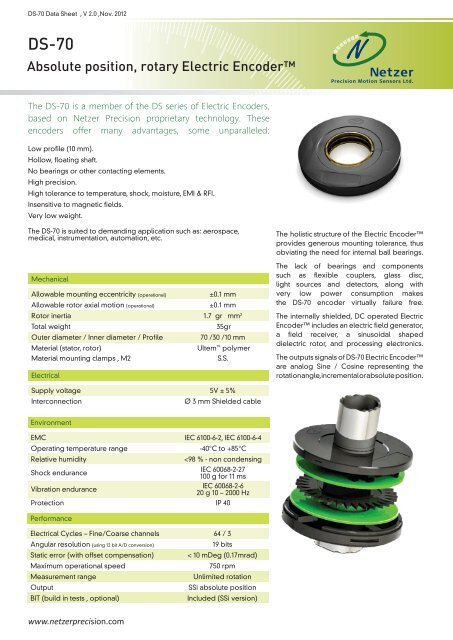
<strong>DS</strong>-<strong>70</strong> <strong>Data</strong> <strong>Sheet</strong> , V 2.0 ,Nov. 2012<strong>DS</strong>-<strong>70</strong>Absolute position, rotary Electric EncoderThe <strong>DS</strong>-<strong>70</strong> is a member of the <strong>DS</strong> series of Electric Encoders,based on <strong>Netzer</strong> Precision proprietary technology. Theseencoders offer many advantages, some unparalleled:Low profile (10 mm).Hollow, floating shaft.No bearings or other contacting elements.High precision.High tolerance to temperature, shock, moisture, EMI & RFI.Insensitive to magnetic fields.Very low weight.The <strong>DS</strong>-<strong>70</strong> is suited to demanding application such as: aerospace,medical, instrumentation, automation, etc.The holistic structure of the Electric Encoderprovides generous mounting tolerance, thusobviating the need for internal ball bearings.MechanicalAllowable mounting eccentricity (operational)Allowable rotor axial motion (operational)±0.1 mm±0.1 mmThe lack of bearings and componentssuch as flexible couplers, glass disc,light sources and detectors, along withvery low power consumption makesthe <strong>DS</strong>-<strong>70</strong> encoder virtually failure free.Rotor inertia 1.7 gr · mm 2Total weight35grOuter diameter / Inner diameter / Profile<strong>70</strong> /30 /10 mmMaterial (stator, rotor) Ultem polymerMaterial mounting clamps , M2S.S.ElectricalThe internally shielded, DC operated ElectricEncoder includes an electric field generator,a field receiver, a sinusoidal shapeddielectric rotor, and processing electronics.The outputs signals of <strong>DS</strong>-<strong>70</strong> Electric Encoderare analog Sine / Cosine representing therotation angle, incremental or absolute position.Supply voltage 5V ± 5%InterconnectionØ 3 mm Shielded cableEnvironmentEMC IEC 6100-6-2, IEC 6100-6-4Operating temperature range-40°C to +85°CRelative humidity
Digital - SSi Interface (absolute position)<strong>DS</strong>-<strong>70</strong>Output signal parametersSignal latencyOutput codeSerial output SSiClock SSi~250 μSecBinaryDifferential RS-422Differential RS-422Synchronous Serial Interface (SSi) allows for serial transmissionof absolute position data from the Electric Encoderresponding to controller clock pulses. The Encoder andcontroller are linked by clock and data differential signal lines.Monoflop time 25 μSecClock Frequency0.5 ÷ 2.5 MHzn * TPosition update (Max)29 KHzt1Tt3Electrical parametersClockCurrent consumption~ 180 mA<strong>Data</strong>n n - 1 10SSi - Wires color codet2MSBLSB# Name Color Function1 Clock + GreySSi Clock2 Clock - BlueMonoflop3 <strong>Data</strong> - Yellow4 <strong>Data</strong> + GreenSSi <strong>Data</strong>5 GND Black Ground6 +5V Red Power supplyn = total number of data bits.T = clock period (sec) - user defined.1/T = clock frequency 0.5 ÷ 2.5 MHz (user defined).t1 = minimum time required for the encoder to freeze data and presetthe shift registers before receiving the first rising edge to prompt theMSBt2 = data transmission delay (increases with cable length)t3 = required delay to refresh position data between subsequentposition reads.- 2 -
Digital - SSi Interface (absolute position)<strong>DS</strong>-<strong>70</strong>Software tools:Advanced calibration and monitoring options available by using the Electric Encoder Explorer software ( factorysupplied ) using the NCP (<strong>Netzer</strong> Communication Protocol) , the Encoder Explorer enables:A. Calibration, built-in tests (BIT) and advanced setup.B. Proper mechanical mounting - setup and validationc. Calibration , offsets , CAA and user defined “zero”.Resoluon In bits Steps /360° mDeg /step Arc-sec /step mRad /step18 262,144 1.3733 4.9438 0.02419 (<strong>DS</strong>-<strong>70</strong>) 524,288 0.6866 2.4719 0.01220 1,048,576 0.3433 1.236 0.006Rotor mounting options for stepped shaftEnd of shaftMid shaftEnd of stepped shaft : MA-<strong>DS</strong><strong>70</strong>-004Installation kit’s CAT #Middle of steeped shaft : MA-<strong>DS</strong><strong>70</strong>-002<strong>DS</strong>-<strong>70</strong> rotor 0.05mm S.S. Shims : <strong>DS</strong>-<strong>70</strong>-R-01- 3 -
<strong>DS</strong>-<strong>70</strong> Ordering<strong>DS</strong> - <strong>70</strong> - 64 - S-H - SC- n n n<strong>DS</strong>Product lineOD mmFine EC/ROutputs:S - Digital : SSi0 - flying leadsC- connectorResolution BinaryCode Bit CPRF 17 131,072G 18 262,144H 19 524,2880 - Loose wires 250 mmS - shielded cableR - Strain relief & shielded cableResolution DecimalCode Bit CPRO 17 128,000P 18 256,000Q 19 512,000Interconnection options- 4 -
<strong>DS</strong>-<strong>70</strong> Mounting options <strong>Netzer</strong> Cat No.: CB0001430 AWG twisted pair (3) :2 (30 AWG 25/44 tinned copper , 0.15 PFE to Ø0.6 ± 0.05 ).Provider: Ray-Q USA.Cable:Three 30 AWG twisted pairs.Shield:Tinned copper braided 95% min. coverage.Jacket:0.45 silicon rubber to Ø3.45 ±0.230 AWG twisted pairs (3)Braided shieldJacket 0.45mmPair #123ColorRed / BlackGray / BlueGreen / YellowØ 3.45 ± 0.20- 5 -
<strong>DS</strong>-<strong>70</strong> - 6 -