A Blendshape Model that Incorporates Physical Interaction
A Blendshape Model that Incorporates Physical Interaction
A Blendshape Model that Incorporates Physical Interaction
- No tags were found...

Create successful ePaper yourself
Turn your PDF publications into a flip-book with our unique Google optimized e-Paper software.
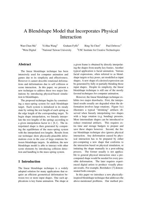
A <strong>Blendshape</strong> <strong>Model</strong> <strong>that</strong> <strong>Incorporates</strong> <strong>Physical</strong><strong>Interaction</strong>Wan-Chun Ma 1 Yi-Hua Wang 2 Graham Fyffe 3 Bing-Yu Chen 2 Paul Debevec 31 Weta Digital 2 National Taiwan University 3 USC Institute for Creative TechnologiesAbstractThe linear blendshape technique has beenintensively used for computer animation andgames due to its simplicity and effectiveness.However it cannot describe rotational deformationsand deformations due to self collision orscene interaction. In this paper, we present anew technique to address these two major limitationsby introducing physical-based simulationto blendshapes.The proposed technique begins by constructinga mass-spring system for each blendshapetarget. Each system is initialized in its steadystate by setting the rest length of each spring asthe edge length of the corresponding target. Tobegin shape interpolation, we linearly interpolatethe rest lengths of the springs according toa given interpolation factor α ∈ [0,1]. The interpolatedshape is then generated by computingthe equilibrium of the mass-spring systemwith the interpolated rest lengths. Results fromour technique show physically-plausible deformationseven in the case of large rotations betweenblendshape targets. In addition, the newblendshape model is able to interact with otherscene elements by introducing collision detectionand handling to the mass-spring system.1 IntroductionThe linear blendshape technique is a widelyadopted solution for many applications <strong>that</strong> requirean efficient geometrical deformation betweentwo or more input shapes. One such applicationsis key frame animation. The shape ata given frame is obtained by directly interpolatingthe shapes from nearby key frames. Anothertypical application is facial animation. Variousfacial expressions, often referred to as blendshapetargets or key poses, are modelled as inputshapes. A new shape of a desired expression canbe generated by fully or partially blending thoseinput shapes. Despite its simplicity, the linearblendshape technique is still one of the mostlyfavored techniques for computer animation.However, the linear blendshape technique exhibitstwo major drawbacks. First, the interpolatedresults usually are degraded when the deformationinvolves large rotations. Figure 1(c)illustrates a typical “shrinking” artifacts observedwhen linearly interpolating two shapeswith a large rotation (e.g. bending) presents.More intermediate shapes can be introduced toreduce rotational artifacts. This requires extratime and storage budgets to prepare andsave these shapes however. Second, the linearblendshape technique also ignores physicalinteraction. Any deformation caused by physicalinteraction has to be prepared by eitherpre-computing a new shape <strong>that</strong> conforms tothe interaction based on physical simulation, orimitating the shape manually in a post-editingprocess. The former usually is not applicableto general physical interaction since a precomputedshape would be needed for every possibledeformation. The later requires experienceddigital artists to produce visually pleasantresults. For example, Borshukov [7] demonstratedboth concepts.In this paper we introduce a new physicallyinspiredblendshape technique <strong>that</strong> addresses theabove-mentioned problems. Our method pro-
(a) (b) (c) (d)Figure 1: A comparison between linear blendshape and our technique. (a) Source shape. (b) Targetshape. (c) Linearly interpolated with α = 0.5. (d) Interpolated by the proposed method withthe same α.(a) (b) (c) (d) (e) (f)Figure 2: The proposed technique enables physically-plausible deformation. (a) Source shape. (b)Target shape. (c-f) Interpolating between the two shapes while interacting with a solidcylinder.vides a physical underpinning for shape interpolationusing mass-spring physics. A key observationis <strong>that</strong> the equilibrium state of a massspringsystem minimizes local area/volume distortionsthrough force balancing. As a result, localrigidity can be maintained as much as possibleduring deformation. The underlying massspringsystem also provides a natural frameworkfor physical interaction. It can be easily carriedout by applying external forces and additionalconstraints based on collision detection.The proposed method begins with building amass-spring system for each input blendshapetargets. The mass-spring system is initializedto its steady state by setting the rest length ofeach spring to the length of the correspondingedge. We then interpolate the rest lengths ofthe springs based on a given interpolation factorand solve for the equilibrium state of the interpolatedmass-spring system, where the final vertexpositions represent the interpolated shape.The equilibrium computation is the major costof the technique. We demonstrate our blendshapetechnique with a wide variety of shapes<strong>that</strong> exhibit complicated geometry and deformations.The method yields more natural shape interpolations,which can be seen in Figure 1(d).Figure 2 shows interpolated results while interactingwith a scene element.Contributions. Two substantial contributions inour work are:1. An algorithm <strong>that</strong> creates natural lookingblendshape interpolation results based oninterpolating the rest length of each springof a mass-spring system. The proposedmethod requires no geometric analysis, articulatedskeleton, or any manual intervention.Since it does not require a skeletonto drive the deformation, it is not limited toarticulated shapes.2. We provide a natural physical interactioncapability, which has not been seen in traditionalshape interpolation techniques, byapplying additional collision detection andhandling. The proposed shape interpolationexhibits correct deformation based oninteraction with other scene elements andwithout requiring any pre-computation.
2 Related WorkOur technique relates to works for interpolatingbetween shapes in two or three dimensions,mass-spring systems, and rest length animation.Shape Interpolation and Deformation. Shapeinterpolation has been widely used for animatinggeometric deformation. The linear blendshapetechnique is the most common methodfor shape interpolation. Shape interpolationcan also be achieved using an articulated skeleton.The skeleton may be manually specified[15,35,37], or automatically determined byfinding near-rigid components of input shapes[11] or using the medial axis transform [6, 38].Rohmer et al. [27] proposed a skinning methodwhich exactly preserves (or controls) the volumeof an object.Other methods are free of using an articulatedskeleton. One effective research trend isbased on maintaining the rigidity criteria of localgeometrical elements, or so-called “as-rigidaspossible” principle. [1] and [16] are typicalexamples of this approach. Baxter et al. [4] proposeda solution for solving the rotation ambiguityarising from previous rigid as-rigid-as possibleapproaches. Winkler et al. [36] interpolatededge lengths and dihedral angles of the inputshapes, followed by a global multi-registrationmethod to determine the best rigid transformation.There are also methods <strong>that</strong> create shapeinterpolation <strong>that</strong> conforms to user manipulation.Barbič et al. [3] proposed a method forkey frame animation based on an underlyingphysically-based simulation, which, similar toour approach, can also be driven by a massspringsystem. Both their method and ours computean equilibrium state as the interpolated result.However, their method interpolates the deformationforces, which are either provided bya user or computed automatically based on keyposes. Our method simply interpolates springrest lengths. Kondo et al. [18] provided guidedanimations with dynamics. A user can have controlsover trajectory and deformation. Their targettrajectory is not obtained via proper shapeinterpolation, but just by pushing the object intonext key frame. Lewis and Anjyo [20] introduceda direct manipulation method for blendshapes.This approach constrains any desiredsubset of vertices based on manual manipulationsand automatically infers the remaining vertexpositions. However, the method only produceshapes <strong>that</strong> are within the convex space ofthe original blendshape poses and has no physicalmeaning.Other related works on shape interpolationor deformation include [12], which used exampleshapes to build a reduced deformable modelwhich controls with mesh-based inverse kinematics.Galoppo et al. [14] introduced the conceptof dynamic morph targets, to skeletally interpolateelastic forces, which allows controlover geometry and elastic properties of an animatedcharacter. Teran et al. [32] solved quasistaticstates of a finite element system for simulatingdeformations of nonlinear elastic materials.We also solve for quasi-static states andconsider interaction with other rigid bodies butwe only balance the mass-spring system with respectto varying the rest lengths.Lewis et al. [21] regards shape interpolationas a scattered data interpolation problemin an abstract parameter (pose) space. Ourmethod does not require high dimensional scattereddata interpolation, and it interpolates shapewith the support of physical simulation, presumablyrequiring fewer input shapes. Kilianet al. [17] presented an isometric deformationmethod based on Riemannian geometry,considering shape interpolation as a geodesiccurve in shape space. Both of these previoustechniques are unable to provide interaction capabilitiesbecause they lack an underlying physicalapproach.Mass-Spring Systems. Mass-spring systemsare commonly used for simulating physical behaviors.Generally, such systems are easy to implementand convenient to integrate with othertechniques, such as collision detection. Applications<strong>that</strong> make use of a mass-spring system includesurgical simulation [22], dynamics for animals[23], cloth [2,10,13], muscles [9,24], andother deformable objects. Lee et al. [19] appliedmass-spring systems to facial animation using athree-layered mesh to model the anatomy of humanfacial tissue. While finite element methods(FEM) can deliver more sophisticated andphysically accurate analysis, mass-spring sys-
tems are attractive due to their low computationalcomplexity.Rest Length Animation. There are works <strong>that</strong>simulate muscle activation through controllingthe rest length of each spring in a mass-springsystem. Raibert and Hodgins [26] used restlength animation to simulate simple leg locomotion.Adjusting the rest length changes theforce at each spring so <strong>that</strong> it is able to initiate orterminate its motion. Tu and Terzopoulos [33]constructed a mass-spring system of a fish body,and assigned some springs to be muscle springsdriven by animated rest lengths. However, theseearlier techniques were not applied to shape interpolation.3 Blending Shapes with a MassSpring SystemThe proposed blendshape technique consists ofthe following two steps:1. Given a set of input blendshape targets,we construct a mass-spring system for eachblendshape target based on its structure.2. We interpolate rest lengths between two ormore aforementioned mass-spring systemsto generate a intermediate mass-spring system.The interpolated shape is the quasistaticstate of the intermediate system.3.1 Structure of the Mass Spring SystemIt is important to maintain the stability of themass-spring system during interpolation, andthis mostly depends on a good spring structure.Based on [10], we build the mass-spring systembased on input triangulated mesh as a combinationof structure springs and bending springs.The structure springs model the elastic propertiesof the mesh surface, connecting neighboringvertices. The bending springs define the bendingand flexural properties of the material, and connecta vertex to secondary neighboring vertices(i.e., at a distance of 2). These bending springshelp maintain the object’s resting shape and preservesurface curvature.Nevertheless, our experiments show <strong>that</strong> alarge surface which consists of many small trianglestends to be crumpled during interpolationG 0 G 1 G 2(0.70, 0.10, 0.20) (0.33, 0.33, 0.33) (0.12, 0.75, 0.12)Figure 3: Blending between multiple shapes.The top row shows three source shapesand the bottom row shows blendedresults with corresponding weightsshown as (w 0 ,w 1 ,w 2 ).due to insufficient numerical precision. To solvethis problem, we insert additional springs insidethe shape to help preserve volume. We applyconstrained Delaunay tetrahedralization [31] todetermine where to insert these internal springs.Similar to the mesh refinement step in [1], toprevent springs with long rest lengths we canalso perform mesh refinement by inserting newvertices. Those vertices have to be added to allthe input shapes correspondingly. Certain additionalvertices <strong>that</strong> are inside the input shapescan be assigned as an anchor as described inSection 3.4.A mass-spring system M = 〈V,S〉 is definedby a collection of vertices V = {v i |i = 1...n v }connected by springs S = {s q |q = 1...n s }. Eachspring s q ∈ S connects two vertices v eq0 andv eq1 , where e q0 = e(s q ,0) and e q1 = e(s q ,1) andfunction e returns the indices of spring s q ’s twovertices. We enforce 1 ≤ e q0 < e q1 ≤ n v . Inaddition, s q is characterized by a rest lengthr q = r(s q ) and spring constant k q = k(s q ), wherefunctions r and k return the rest length andspring constant of spring s q , respectively.3.2 Blending between Two ShapesWe first introduce our technique by explainingthe case of blending between two shapes G 0 and
G 1 . We build two consistent mass-spring systemsM 0 = 〈V 0 ,S 0 〉 and M 1 = 〈V 1 ,S 1 〉 fromG 0 and G 1 . The two mass-spring systems areinitially set to be in their own steady states, i.e.rq 0 =‖ v 0 e q0− v 0 e q1‖ and rq 1 =‖ v 1 e q0− v 1 e q1‖. Foreach α ∈ [0,1], the interpolated result from theinput shapes is the equilibrium state of a newmass-spring system ¯M = 〈 ¯V, S〉, ¯ where for eachspring,¯r q = (1 − α)rq 0 + αrq. 1 (1)In an equilibrium state, the force f (v i ) at eachvertex v i in M equals zero:f (v i ) = ∑ k q (‖v i − v j ‖ − r q ) v i − v j‖vj∈n(i)i − v j ‖ = 0,(2)where function n returns the indices of thosevertices <strong>that</strong> are adjacent to v i , and spring s qconnects v i and v j . Note <strong>that</strong> the velocity ofeach vertex can be ignored since our results arebased solely on quasi-static states. We assume<strong>that</strong> each vertex has the same mass, thereforethe mass term can also be ignored. To formulateEq. (2) into a linear system, first we vectorize Vinto an one dimensional vector x as:x = [x(v 1 ),y(v 1 ),z(v 1 ),···,x(v nv ),y(v nv ),z(v nv )] T ,where x(v i ),y(v i ),z(v i ) are functions <strong>that</strong> returnthe X, Y and Z Cartesian coordinates of v i . Thesystem is then solved by using the Newton–Raphson method to determine the first order approximationof the optimal vertex configuration:f (x t+1 ) ≈ f (x t ) + J(x t )∆x t , (3)where x t+1 = x t + ∆x t and J(x t ) = ∂ f∂x (x t) is theglobal stiffness (Jacobian) matrix of f evaluatedat the current vertex positions x t . When thesystem is in its equilibrium state f (x t+1 ) = 0.Eq. (3) now becomes:J(x t )∆x t = − f (x t ). (4)The non-diagonal elements of the global stiffnessmatrix J i j are defined by:)J i j = J ji = k q(r q‖ d i j ‖ 2 I − d i j d T i j‖ d i j ‖ 3− I,where I is an identity matrix, d i j = v i − v j , andspring s q connects v i and v j ; or else a 3 × 3 matrixof zeros if no such a spring exists. The diagonalelements (i = j) are defined as:J ii = − ∑ J i j .j∈n(i)x 0 is initialized as the vertex positions of thesource shape V 0 . We then iteratively solveEq. (4) until ‖∆x t ‖ is smaller than a threshold( ¯M reaches its equilibrium). The final vertexpositions are then assigned to ¯V. Generally matrixJ is very sparse. There are both iterative(e.g. conjugate gradient) and direct methods forsolving this sparse linear system.3.3 Blending Multiple ShapesThe proposed technique can also be extended toblending multiple shapes by simply consideringthe interpolated rest length as a convex linearcombination of the spring rest lengths from theinput shapes:¯r q =n b∑i=0w i r i q,where ∑ n bi=0 w i = 1. This is illustrated in Figure3 where the interpolated shapes (shown inyellow) are the results of linearly-blended springrest lengths from three different input shapes(shown in blue). Notice <strong>that</strong> this shares exact thesame formulation for controlling blendshape targetsas as the traditional linear blendshape techniquedoes.3.4 Boundary ConditionsBoundary conditions must be specified in orderto solve the equilibrium of a mass-spring system.Without boundary conditions, the systemwill be under-constrained and the solution willnot be unique. Simply speaking, boundary conditionsare vertices which are fixed in a massspringsystem. In practice, this can be achievedby assigning Dirichlet boundary conditions tothe global stiffness matrix, i.e., by replacing theblock of the global stiffness matrix correspondingto boundary vertices with an identity matrix.The entries of the boundary vertices in fare replaced by zeros to enforce <strong>that</strong> the correspondingvertices do not move. A straightforwardmethod to assign the boundary conditionsis to find vertices which remain static betweenthe source and target shapes. However,
this is unlikely to apply to general blendshapetargets. Alternatively, certain vertices on the surfacecan be manually marked as boundary conditions.During the interpolation, the positionsof the marked vertices are then interpolated linearly.However, we found <strong>that</strong> this method oftendoes not yield visually pleasing results, becausethese marked vertices still follow a linear trajectoryduring interpolation.Similar to [8], we propose a more generalmethod which allows all the surface vertices tomove freely is to use an auxiliary object as ananchor, whose vertex positions act as the boundaryconditions. For example, placing a rectanglearound the center of mass of the object wouldkeep this region fixed through the pose interpolation.We use the following procedure to addan anchor:1. Select an anchor position inside the sourceshape (Figure 4(a)).2. When building the structure of the massspringsystem (as in Section 3), we connectadditional springs to the vertices of the anchor.All the springs belonging to the anchorare set as hard constraints by settinga very large spring constant. This enforcesrigidity during the relaxation detailed in thenext step.3. The rest lengths of the internal springs <strong>that</strong>connect surface vertices to the anchor arecomputed from the source shape based onthe user-assigned anchor positions. However,The rest lengths of these surfaceanchorsprings in the target shape still remainsunknown. We have to determine thelocation of the anchor first. One possiblesolution is to reverse the roles of anchorand shape, i.e., we set all the vertices inthe target shape as the boundary conditions,and copy the rest lengths of the springsconnecting the anchor to the source, thendetermine the positions of anchor verticeswithin the target shape by solving the equilibrium.4. Once the locations of the anchors areknown, we can determine an optimal rigidtransformation T = {R|t} between the anchorsof the source and target shapes such(a) (b) (c)Figure 4: Apply an internal anchor as boundaryconditions. (a) A source shape withan anchor object (a rectangular plane,shown in red) inside. (b) The interpolatedresult. The vertices of the anchoract as the boundary conditions duringthe spring relaxation, thus allowingfree movement of all the surfacevertices. (c) The interpolated resultwith a rigid transformation applied.<strong>that</strong> p 1 i = Rp 0 i +t, where p0 i and p 1 i are thepositions of the source and target anchors’vertices, respectively.5. For each step during the shape interpolation,we move the anchor according tothe linearly-interpolated rigid transformationT ′ = {q(I,R,α)|αt}, where q is thefunction <strong>that</strong> interpolates the identity matrixI and the rotation matrix R with aweight α using quaternions [30]. We subsequentlyfix the interpolated anchor verticesas the boundary conditions and computethe equilibrium state of the massspringsystem. To improve numerical stability,we solve for the equilibrium in thelocal coordinate frame of the (initial) anchor.Afterwards, we reapply the rigidtransformation to both the anchor and theshape. This is illustrated in Figure 4.3.5 Spring ConstantsThe proposed shape interpolation method guaranteesits results reach both of the input shapesas rest states of ¯M i . However, having a uniformspring constant for every spring leads tothe problem <strong>that</strong> longer springs may have largerinfluences at each step of the interpolation ( f =k∆x). To counterbalance this effect, we set thespring constant to be inversely proportional to
the rest length:k q ∝ 1 r q.The strategy ensures every spring, no matterwhat its rest length is, contributes similaramount of force during the interpolation process.4 <strong>Physical</strong> <strong>Interaction</strong>Since the interpolation framework is basedon physical-based simulation (mass-spring system),our method is able to physically interactwith other objects during the interpolation. Duringeach interpolation step, we perform collisiondetection between the mass-spring systemand obstacles. An axis-aligned bounding box(AABB) tree structure is built for both objectsto accelerate the detection. The following proceduresare executed once collisions are reported:1. Move the intersecting vertices back to thesurface of the obstacle according to thepenetration normals.2. Enforce all the intersecting vertices as additionalboundary conditions. However,sometimes the deformation might be toolarge such <strong>that</strong> both surface and internalvertices (as described in Section 3.1) areinvolved in the intersection. In this case,we only use surface vertices as the boundaryconditions. The internal vertices neverbecome fixed due to a collision in order topreserve the internal structure.3. Recompute the equilibrium state.This produces a result which preserves the originalshape’s features as much as possible, whilerespecting to the collision constraints. Figures 2and 5 show interpolation results while physicalinteractions are applied.5 ResultsFigure 6 shows several results (yellow) resultingfrom interpolation of the input shapes (blue).The supplemental video provides additional examplesof our technique. Our interpolationFigure 5: <strong>Physical</strong> interactions. The top rowshows the original interpolation. Thebottom row shows the same interpolationwhile a vertex is pulled away fromthe face. Parts of the mesh boundaryare fixed as boundary conditions.method is able to produce visually pleasant motionsfrom just a few example shapes (e.g. theopening and closing of the hand). It also successfullydemonstrates physical interaction capabilities.Implementation. A sparse matrix solver is requiredfor Eq. (3). For our implementationwe have tried both the CPU-based PARDISO[28, 29], and the GPU-based Cusp [5]. SOLID[34] is used for collision detection. Table 1 liststhe statistics of each shape interpolation. All theresults are generated on a desktop computer witha 2.66GHz Intel Core 2 Quad CPU, an NVIDIAQuadro FX 580 GPU, and 3.0GB main memory.The actual execution time for each Newton–Raphson step is to a large extent determined bythe complexity of the mass-spring system.Limitations. A mass-spring system may havemore than one equilibrium. This leads to an elementinversion problem. We found <strong>that</strong> the elementinversion problem is more likely to occurif the input shapes originally contains folds dueto self-intersecting triangles.6 Conclusion and Future WorkIn this paper, we presented a new blenshapetechnique where the interpolated shape is definedas the equilibrium state of a interpolated
Shape n v n s t CPU t GPUMan 2.2k 21.6k 2.23 3.62Face 8.1k 65.1k 40.11 3.67Cat 7.3k 81.7k 67.58 13.67Horse 8.5k 96.1k 81.36 15.95Hand 18.6k 150.4k 153.99 26.28Table 1: Statistics on the size of the input shapesand average running time per interpolationstep (in seconds), assumingthere are 36 steps for the interpolationbetween the source and target for allthe experiments. n v : number of vertices(including internal and anchor vertices),n s : number of springs, t CPU : runningtime with the PARDISO solver,t GPU : running time with the Cuspsolver.mass-spring system. The proposed technique isfully automatic, requires no additional geometricalanalysis or skeleton, and generates physicallyplausible shape interpolation with low distortionof surface area and volume. It also followsthe linear blending control strategy usedin traditional blendshapes. Digital artists whoare familiar with traditional linear blendshapetechnique can potentially convert to our methodwithout much efforts.Our currently implementation does notachieve real-time performance, however forpost production use this is not a critical issue.We are still exploring how to accelerate thistechnique. One possible method is to computethe deformation using a multi-resolution strategy,or to enforce the positive definiteness ofthe global stiffness matrix and use a faster conjugategradient solver as described in [32]. Ourcurrent implementation for collision handling isalso very simplified (e.g. let the contact verticesbe fixed by assigning them as the boundaryconditions). Friction force should be consideredfor better simulation. We would also like toinvestigate the effect of heterogeneous springconstants analogous to those in [25].7 AcknowledgementThe authors would like to thank reviewers fortheir comments and suggestions. We are alsograteful to the help from J.P. Lewis at Weta Digitaland Jernej Barbič at University of SouthernCalifornia during the preparation of this paper.This research was partially supported by the NationalScience Council, Taiwan under NSC98-2221-E-002-140-MY2.References[1] M. Alexa, D. Cohen-Or, and D. Levin. Asrigid-as-possibleshape interpolation. InProceedings of SIGGRAPH 2000, pages157–164.[2] D. Baraff and A. Witkin. Large steps incloth simulation. In Proceedings of SIG-GRAPH 1998, pages 43–54.[3] J. Barbič, M. da Silva, and J. Popović. Deformableobject animation using reducedoptimal control. ACM Transactions onGraphics, 28(3):1–9, 2009.[4] W. Baxter, P. Barla, and K. Anjyo. Rigidshape interpolation using normal equations.In Proceedings of the 2008 InternationalSymposium on Non-PhotorealisticAnimation and Rendering, pages 59–64.[5] N. Bell and M. Garland. Cusp: Genericparallel algorithms for sparse matrix andgraph computations, 2010.[6] J. Bloomenthal. Medial-based vertex deformation.In Proceedings of the 2002ACM SIGGRAPH/Eurographics Symposiumon Computer Animation, pages 147–151.[7] G. Borshukov. Making of the superpunch.In ACM SIGGRAPH 2005 Courses.[8] C. Bregler, L. Loeb, E. Chuang, andH. Deshpande. Turning to the masters:motion capturing cartoons. In Proceedingsof SIGGRAPH 2002, pages 399–407.[9] J. E. Chadwick, D. R. Haumann, andR. E. Parent. Layered construction for deformableanimated characters. Proceedingsof SIGGRAPH 1989, pages 243–252.
Figure 6: Results of shape interpolation using the proposed method. The input shapes are blue, whileinterpolated shapes are yellow. Table 1 lists the number of vertices, number of springs, andtimings for each shape.[10] K.-J. Choi and H.-S. Ko. Stable but responsivecloth. In Proceedings of SIG-GRAPH 2002, pages 604–611.[11] H.-K. Chu and T.-Y. Lee. Multiresolutionmean shift clustering algorithm forshape interpolation. IEEE Transactionson Visualization and Computer Graphics,15(5):853–866, 2009.[12] K. G. Der, R. W. Sumner, and J. Popović.Inverse kinematics for reduced deformablemodels. ACM Transactions on Graphics,25(3):1174–1179, 2006.[13] M. Desbrun, P. Schröder, and A. Barr.Interactive animation of structured deformableobjects. In Proceedings of theGraphics Interface 1999, pages 1–8.[14] N. Galoppo, M. Otaduy, W. Moss, J. Sewall,S. Curtis, and M. Lin. Controllingdeformable material with dynamic morphtargets. In Proceedings of the 2009 Symposiumon Interactive 3D Graphics andGames, pages 39–47.[15] J. Huang, X. Shi, X. Liu, K. Zhou, L.-Y. Wei, S.-H. Teng, H. Bao, B. Guo, andH.-Y. Shum. Subspace gradient domainmesh deformation. ACM Transactions onGraphics, 25(3):1126–1134, 2006.[16] T. Igarashi, T. Moscovich, and J. F.Hughes. As-rigid-as-possible shape manipulation.ACM Transactions on Graphics,24(3):1134–1141, 2005.[17] M. Kilian, N. J. Mitra, and H. Pottmann.Geometric modeling in shape space. ACMTransactions on Graphics, 26(3):1–8,2007.[18] R. Kondo, T. Kanai, and K.-i. Anjyo.Directable animation of elastic objects.In Proceedings of the 2005 ACMSIGGRAPH/Eurographics Symposium onComputer Animation, pages 127–134.[19] Y. Lee, D. Terzopoulos, and K. Waters. Realisticmodeling for facial animation. InProceedings of SIGGRAPH 1995, pages55–62.
[20] J. P. Lewis and K.-i. Anjyo. Direct manipulationblendshapes. IEEE ComputerGraphics and Applications, 30(4):42–50,2010.[21] J. P. Lewis, M. Cordner, and N. Fong.Pose space deformation: a unified approachto shape interpolation and skeletondrivendeformation. In Proceedings ofSIGGRAPH 2000, pages 165–172.[22] A. Liu, F. Tendick, K. Cleary, and C. Kaufmann.A survey of surgical simulation:applications, technology, and education.Presence: Teleoperators and Virtual Environments,12(6):599–614, 2003.[23] G. S. P. Miller. The motion dynamics ofsnakes and worms. pages 169–173.[24] L. P. Nedel and D. Thalmann. Real timemuscle deformations using mass-springsystems. In Proceedings of the ComputerGraphics International 1998, pages 156–165.[25] T. Popa, D. Julius, and A. Sheffer.Material-aware mesh deformations. InProceedings of the 2006 IEEE InternationalConference on Shape <strong>Model</strong>ing andApplications, page 22.[26] M. H. Raibert and J. K. Hodgins. Animationof dynamic legged locomotion. InProceedings of SIGGRAPH 1991, pages349–358.[27] D. Rohmer, S. Hahmann, and M.-P. Cani.Exact volume preserving skinning withshape control. In Proceedings of the 2009ACM SIGGRAPH/Eurographics Symposiumon Computer Animation, pages 83–92.[28] O. Schenk, M. Bollhofer, and R. A. Roemer.On large-scale diagonalization techniquesfor the Anderson model of localization.SIAM Journal on Scientific Computing,28(3):963–983, 2006.[29] O. Schenk, A. Wächter, and M. Hagemann.Matching-based preprocessingalgorithms to the solution of saddlepointproblems in large-scale nonconvexinterior-point optimization. Journal ofComputational Optimization and Applications,36:321–341, 2007.[30] K. Shoemake. Animating rotation withquaternion curves. In Proceedings of SIG-GRAPH 1985, pages 245–254, 1985.[31] H. Si and K. Gärtner. Meshing piecewiselinear complexes by constrained delaunaytetrahedralizations. In Proceedings of the2005 International Meshing Roundtable,pages 147–163.[32] J. Teran, E. Sifakis, G. Irving, and R. Fedkiw.Robust quasistatic finite elementsand flesh simulation. In Proceedings ofthe 2005 ACM SIGGRAPH/EurographicsSymposium on Computer Animation,pages 181–190.[33] X. Tu and D. Terzopoulos. Artificial fishes:physics, locomotion, perception, behavior.In Proceedings of SIGGRAPH 1994, pages43–50.[34] G. van den Bergen. SOLID: Software libraryfor interference detection.[35] O. Weber, O. Sorkine, Y. Lipman, andC. Gotsman. Context-aware skeletal shapedeformation. Computer Graphics Forum,26(3):265–274, 2007.[36] T. Winkler, J. Drieseberg, M. Alexa, andK. Hormann. Multi-scale geometry interpolation.Computer Graphics Forum,29(2):309–318, 2010.[37] H.-B. Yan, S. Hu, R. R. Martin, and Y.-L.Yang. Shape deformation using a skeletonto drive simplex transformations. IEEETransactions on Visualization and ComputerGraphics, 14(3):693–706, 2008.[38] S. Yoshizawa, A. G. Belyaev, and H.-P.Seidel. Free-form skeleton-driven meshdeformations. In Proceedings of the 2003ACM Symposium on Solid <strong>Model</strong>ing andApplications, pages 247–253.