VWUSA.COM VW MK5 MKV New Jetta New Model ... - VAGLinks.com
VWUSA.COM VW MK5 MKV New Jetta New Model ... - VAGLinks.com
VWUSA.COM VW MK5 MKV New Jetta New Model ... - VAGLinks.com

You also want an ePaper? Increase the reach of your titles
YUMPU automatically turns print PDFs into web optimized ePapers that Google loves.
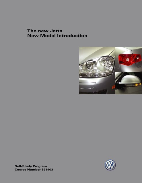
The new <strong>Jetta</strong><br />
<strong>New</strong> <strong>Model</strong> Introduction<br />
Self-Study Program<br />
Course Number 891403
Volkswagen of America, Inc.<br />
Volkswagen Academy<br />
Printed in U.S.A.<br />
Printed 12/2004<br />
Course Number 891403<br />
©2004 Volkswagen of America, Inc.<br />
All rights reserved. All information contained<br />
in this manual is based on the latest<br />
information available at the time of printing<br />
and is subject to the copyright and other<br />
intellectual property rights of Volkswagen of<br />
America, Inc., its affiliated <strong>com</strong>panies and its<br />
licensors. All rights are reserved to make<br />
changes at any time without notice. No part<br />
of this document may be reproduced,<br />
stored in a retrieval system, or transmitted in<br />
any form or by any means, electronic,<br />
mechanical, photocopying, recording or<br />
otherwise, nor may these materials be<br />
modified or reposted to other sites without<br />
the prior expressed written permission of<br />
the publisher.<br />
All requests for permission to copy and<br />
redistribute information should be referred<br />
to Volkswagen of America, Inc.<br />
Always check Technical Bulletins and the latest<br />
electronic repair information for information<br />
that may supersede any information included<br />
in this booklet.<br />
Trademarks: All brand names and product<br />
names used in this manual are trade names,<br />
service marks, trademarks, or registered<br />
trademarks; and are the property of their<br />
respective owners.
Introduction ................................................................................1<br />
Course Introduction, The <strong>New</strong> <strong>Jetta</strong><br />
Body ............................................................................................6<br />
Chassis Construction, Exterior Parts, Windows, Hood Latch<br />
Cable, <strong>New</strong> Door Design, Seat Design Features, Storage<br />
Areas<br />
Passenger Safety ......................................................................20<br />
Overview, Two-Stage Airbags, Advanced Airbag System,<br />
Active Front Seat Head Restraints, Rear Side Head Airbags,<br />
Side Airbag Crash Sensors<br />
Engines......................................................................................26<br />
2.5L/150 HP 5-Cylinder Engine with 4-Valves per Cylinder,<br />
2.0L/200 HP 4-Cylinder Turbo FSI Engine with 4-Valves per<br />
Cylinder, 1.9L/105 HP TDI Engine with 2-Valve Technology,<br />
Pedal Assembly<br />
Automatic Transmission...........................................................52<br />
6-Speed Direct Shift Gearbox (DSG) 02E, 6-Speed Automatic<br />
Transmission 09G<br />
Suspension ...............................................................................54<br />
Suspension Features<br />
Electrical System ......................................................................56<br />
Fuse and Relay Locations, CAN Networking Concept, Air<br />
Conditioning Systems<br />
Heating and Air Conditioning .................................................62<br />
Introduction, Air Distribution System, Overview of the Dual<br />
Zone Climatronic/Climatic System, Sensors, Actuators<br />
Radio and Navigation ..............................................................75<br />
Radio and Navigation Systems<br />
Service.......................................................................................77<br />
Special Tools, <strong>New</strong> Special Tools<br />
This Self-Study Program covers the design and operation of<br />
the new <strong>Jetta</strong>!<br />
This Self-Study Program is not a Repair Manual. This<br />
information will not be updated.<br />
For testing, adjustment and repair procedures, always refer<br />
to the latest electronic service information.<br />
Table of Contents<br />
<strong>New</strong>!<br />
Important/Note!<br />
i
Course Introduction<br />
The new <strong>Jetta</strong> continues its success story<br />
of the past 30 years. The new <strong>Jetta</strong><br />
introduces new features that <strong>com</strong>bine<br />
appearance with <strong>com</strong>fort and modern<br />
technology, resulting in a vehicle that<br />
provides the ultimate value in its class.<br />
Attention to detail, increased horsepower,<br />
added safety features and subtle quality<br />
improvements set the new <strong>Jetta</strong> apart from<br />
the <strong>com</strong>petition.<br />
The new <strong>Jetta</strong> is built at Volkswagen's<br />
Puebla, Mexico plant. This plant began<br />
operation in 1964, manufacturing the old<br />
style Beetle. Currently, the Puebla plant<br />
employs approximately 14,000 people and<br />
also produces the <strong>New</strong> Beetle, among<br />
other vehicles.<br />
Additional self-study programs relating to the new <strong>Jetta</strong> include:<br />
• SSP 851503: 6-Speed Automatic Transmission 09G/09K/09M<br />
• SSP 851403: The Direct Shift Gearbox 02E<br />
• SSP 892403: The Electro-Mechanical Power-Assisted Steering<br />
• SSP 873403: The new <strong>Jetta</strong>–Electrical System Design and Function<br />
• SSP 861403: The new <strong>Jetta</strong>–Steering and Suspension<br />
Introduction<br />
<strong>New</strong> <strong>Jetta</strong> features include:<br />
• Elegant design<br />
• Superior quality<br />
• Excellent handling dynamics<br />
• Comprehensive safety package<br />
• Innovative drivetrain technology<br />
• Improved economy<br />
• Spacious interior<br />
• Customer focused innovations<br />
1
Introduction<br />
The <strong>New</strong> <strong>Jetta</strong><br />
The new <strong>Jetta</strong> sets new standards for its<br />
class in many areas, including:<br />
• Safety<br />
• Quality<br />
• Design<br />
• Handling<br />
• Roominess<br />
• Drivetrain<br />
2<br />
• Electro-mechanical<br />
power steering<br />
• 2.5L 150 HP 5-Cylinder Engine<br />
with 4-Valves per Cylinder<br />
• Optional Bi-Xenon headlights<br />
• Many storage locations such as<br />
the overhead console<br />
• ABS/ESP MK 60<br />
• Premium sound system
Other Features<br />
• Rain sensing windshield wipers<br />
• Optional rear distance warning system<br />
S891403_102<br />
• Dual zone climate control<br />
Introduction<br />
• Two piece tail light design<br />
• Four link independent suspension<br />
• Customer personalization via the<br />
multi-function indicator (MFI) switch lever<br />
3
Introduction<br />
Technical Specifications<br />
The figure shows the dimensions of the<br />
front-wheel drive new <strong>Jetta</strong>.<br />
Weights and Exterior Dimensions<br />
Length<br />
Width<br />
Height<br />
Wheelbase<br />
4<br />
34.6 in.<br />
(880mm)<br />
60.4 in.<br />
(1,533mm)<br />
69.1 in.<br />
(1,755mm)<br />
178.1 in. (4,523mm)<br />
69.1 in. (1,755mm)<br />
57.5 in. (1,461mm)<br />
101.5 in. (2,578mm)<br />
S891403_01<br />
101.5 in.<br />
(2578mm)<br />
178.1 in.<br />
(4523mm)<br />
57.5 in.<br />
(1,461mm)<br />
Front track width<br />
Rear track width<br />
Maximum weight<br />
Empty weight<br />
59.7 in.<br />
(1,517mm)<br />
42.7 in.<br />
(1084mm)<br />
S891403_16<br />
S891403_15<br />
60.4 in. (1,533mm)<br />
59.7 in. (1,517mm)<br />
4,057 to 4,321 lb.*<br />
(1,840 to 1,960 kg)<br />
3,016 to 3,331 lb.*<br />
(1,368 to 1,511 kg)<br />
*varies depending on model<br />
S891403_02
Interior Dimensions<br />
1 Front seat headroom 37.4 to 38.4 in.<br />
(949 to 975mm)<br />
2 Back seat headroom 37.0 to 37.2 in.<br />
(941 to 945mm)<br />
*varies depending on model<br />
S891403_03<br />
1 2<br />
Introduction<br />
S891403_12<br />
5
Body<br />
Chassis Construction<br />
Static and Dynamic Rigidity<br />
The new <strong>Jetta</strong> sets new standards for static<br />
and dynamic rigidity by the application of<br />
lightweight design principles.<br />
Fenders, doors and side panels are all made<br />
of high strength steel.<br />
Laser Weld Technology<br />
The assembly plant in Puebla, Mexico<br />
makes extensive use of laser welding<br />
technology to produce the new <strong>Jetta</strong><br />
chassis. The increased use of laser welds<br />
has resulted in significant improvements in<br />
chassis strength and rigidity.<br />
Laser weld technology not only improves<br />
manufacturing efficiency, it also improves<br />
the quality of the chassis by increasing the<br />
welded surface while reducing the<br />
deformation of the sheet metal caused by<br />
the necessary heat and pressure of<br />
previous welding methods.<br />
The chart below provides a <strong>com</strong>parison of<br />
increased manufacturing technology on the<br />
new <strong>Jetta</strong> A5 <strong>com</strong>pared to the previous<br />
<strong>Jetta</strong> A4.<br />
6<br />
Key:<br />
Red = Side Impact Zone<br />
Yellow = Occupant Cell<br />
Blue = Frame Structure
B-pillar<br />
The new <strong>Jetta</strong>’s B-pillar consists of three<br />
hot formed panels that provide improved<br />
passenger protection in the event of a<br />
side-impact collision.<br />
Additional side impact<br />
protection in doors<br />
S891403_19<br />
Outer Body Side<br />
Panel<br />
B-pillar<br />
Body<br />
S318_066<br />
Inner Body Side Panel<br />
(tailored blank)<br />
Hot Formed Panels<br />
The B-pillar and adjacent portion of the<br />
body in the direction of the A-pillar are heat<br />
treated during the forming process to<br />
increase strength. These hot formed panels<br />
are stronger and weigh less than the panels<br />
on previous models.<br />
Hot formed panels<br />
S891403_18<br />
S891403_17<br />
7
Body<br />
Exterior Parts<br />
Impact-Absorbing Foam<br />
Headlights<br />
The <strong>Jetta</strong> headlights feature clear glass. The<br />
turn signals are located below the low and<br />
high beam headlights to improve their<br />
visibility to other drivers.<br />
Bi-Xenon headlights are available as an<br />
option on some models.<br />
8<br />
S318_289<br />
S891403_115<br />
Front Bumper<br />
By integrating an impact-absorbing foam<br />
element into the front bumper behind the<br />
front spoiler, the risk of injury to<br />
pedestrians is reduced. This deformable<br />
foam element allows <strong>com</strong>pression of the<br />
front bumper during impact.
Exterior Rearview Mirrors<br />
Turn signals are integral to the exterior<br />
rearview mirrors.<br />
S891403_26<br />
S891403_117<br />
Tail Lights<br />
The new <strong>Jetta</strong> has two-part tail lights.<br />
Body<br />
S891403_116<br />
9
Body<br />
Windows<br />
The windows on the new <strong>Jetta</strong> are greentinted<br />
glass (blue-tinted glass will be<br />
available at a later date). The thickness of<br />
the window glass depends on its location:<br />
the windshield is .17 inches (4.4mm), the<br />
front side windows are .14 inches (3.5mm)<br />
and all other windows are .12 inches<br />
(3.15mm). All fixed windows are bonded to<br />
the body.<br />
Windshield<br />
Label<br />
10<br />
Sealing Lip<br />
Drip<br />
Molding Area<br />
Area Below<br />
the Hood<br />
Ceramic Coating as Third Sun Visor<br />
Sash for Plenum Chamber Cover<br />
Windshield<br />
The windshield is available with an infraredreflective<br />
metal vapor deposition coating.<br />
This coating reflects most of the sun’s heat<br />
generating infrared rays. Conventional<br />
reflective glass shields a vehicle’s interior<br />
from far less solar radiation by absorption.<br />
Always set the windshield on its<br />
side. Otherwise, the sash at the<br />
bottom and/or the sealing lip at<br />
the top can be<strong>com</strong>e damaged.<br />
Clear Area for<br />
Rain/Light Sensors<br />
Drip Molding<br />
Area<br />
S318_003<br />
Clear Area for VIN Plate
Rear Window<br />
Replacement rear windows are produced<br />
with integral diversity antennas. Diversity<br />
antennas connect to the diversity switching<br />
box by two terminals on the window.<br />
Antenna Terminal<br />
Heater Element<br />
Terminal<br />
Heater element with additional printed conductors for<br />
optimizing the rear window antennas<br />
Be sure to order the correct rear<br />
window when replacing to assure<br />
all electrical terminals are<br />
present.<br />
Body<br />
Signals are relayed simultaneously from<br />
these terminals to the radio and the<br />
diversity switching box. Using both antenna<br />
signals significantly reduces interference.<br />
Antenna<br />
Terminal<br />
S318_005<br />
Heater Element<br />
Terminal<br />
11
Body<br />
Hood Latch Cable<br />
The hood latch cable (bowden cable) for<br />
releasing the hood latch from inside the<br />
passenger <strong>com</strong>partment is located in a<br />
protected area in the engine <strong>com</strong>partment.<br />
The hood latch cable disconnect point is<br />
located under the hood behind the<br />
driverside headlight assembly. This allows<br />
front end service without removing the<br />
cable from the vehicles interior.<br />
12<br />
Disconnect point (closed)<br />
Disconnect point (open)<br />
Bowden cable disconnected<br />
S891403_47<br />
S318_251<br />
S318_253<br />
S318_255
Emergency Release Mechanism<br />
Removing the interior trunk trim allows<br />
access to the locking linkage for emergency<br />
release of the trunk.<br />
S891403_104<br />
Body<br />
S891403_46<br />
13
Body<br />
<strong>New</strong> Door Design<br />
The doors on the new <strong>Jetta</strong> consist of an<br />
outer panel with two mounting rails and an<br />
inner section for mounting hardware. The<br />
door’s outer panel is bonded to the<br />
mounting rails that are bolted to the inner<br />
section.<br />
14<br />
Door Outer<br />
Panel<br />
Cover Strip<br />
Mounting Rail<br />
Removal of the outer door panel allows<br />
access to some of the door’s inner<br />
hardware and electronics, the window<br />
motor is accessed through the inside. Also,<br />
in the event of door damage, the outer<br />
panel can be removed for repair or<br />
replacement.<br />
Door Inner Section<br />
Side Impact Bar<br />
Check the current service repair<br />
information for instructions on<br />
outer door panel removal.<br />
Mounting Rail<br />
S318_257<br />
Cover Strip
Mounting Rails<br />
The mounting rails are permanently bonded<br />
to the outer panel with adhesive. This<br />
ensures an accurate fit when the outer<br />
panel is bolted to the door's inner section.<br />
Internal Door Components<br />
Removing the outer panel allows easy<br />
access to the side impact bars, door handle<br />
bracket, door lock, side airbag crash sensor<br />
and the window regulator module.<br />
Window<br />
Regulator<br />
Module<br />
Side Impact Bars<br />
Mounting<br />
Rails<br />
Door Outer Panel<br />
Driver’s Side Airbag Crash<br />
Sensor G179<br />
S318_205<br />
Body<br />
S318_203<br />
Door Handle<br />
Bracket<br />
Door Lock<br />
15
Body<br />
Seat Design Features<br />
Front Seats<br />
The front seats on the new <strong>Jetta</strong> are<br />
equipped with an active head restraint<br />
system. Options include: a mechanical<br />
2-way lumbar support or an electrical 4-way<br />
lumbar support.<br />
The active head restraint system is a<br />
mechanical system that moves the driver<br />
and passenger head restraints upward and<br />
forward in the event of a rear end collision.<br />
S891403_118<br />
Height Adjustment<br />
Power Backrest<br />
16<br />
S891403_119<br />
4-Way Lumbar Support<br />
1. Through-Loading Front Passenger Seat<br />
2. Rear Loading Door<br />
3. Active Head Restraints<br />
4. 4-Way Lumbar Support<br />
5. Power Backrest<br />
6. Complete Power Seat, Optional<br />
Active Head<br />
Restraint System<br />
4-Way Lumbar<br />
Support<br />
S318_060<br />
S891403_94
An optional feature of the front passenger<br />
seat allows it to be folded flat for loading<br />
and hauling of long items by using the full<br />
length of the interior.<br />
S318_101<br />
Rear Seats<br />
The rear seat cushion extends across the<br />
full width of the interior. The backrest is<br />
split 60/40 and can be folded down. The<br />
backrests lock using a rotary latch. A red<br />
indicator shows if the backrests are locked<br />
or not.<br />
A red indicator showing<br />
means that the backrest<br />
is not locked in position.<br />
S318_207<br />
S318_209<br />
The pass-through door is locked<br />
in position.<br />
S318_211<br />
A red indicator showing means<br />
that the pass-through door is not<br />
locked in position.<br />
Body<br />
On vehicles equipped with the<br />
pass-through option for the rear seat, the<br />
armrest and the door located behind it can<br />
be folded forward to allow transport of long<br />
items such as skis or golf bags.<br />
17
Body<br />
Storage Areas<br />
The new <strong>Jetta</strong> features numerous<br />
convenient storage areas.<br />
Overhead Storage<br />
There is a standard open storage<br />
<strong>com</strong>partment in the overhead console of<br />
the new <strong>Jetta</strong>.<br />
18<br />
Front Storage<br />
Vehicles equipped with air conditioning can<br />
cool the front passengerside storage<br />
<strong>com</strong>partment.<br />
Door Storage<br />
Adjustable<br />
Temperature<br />
Outlet<br />
S318_103<br />
Storage <strong>com</strong>partments, and a cup holder<br />
for 1.6 quart (1.5 liter) bottles are located in<br />
the door panels.<br />
S318_105 S891403_47
Center Console Storage<br />
A new <strong>Jetta</strong> storage option includes an airconditioned<br />
storage <strong>com</strong>partment in the<br />
center console and fold-out cup holders for<br />
the rear seats.<br />
Adjustable<br />
Temperature<br />
Outlet<br />
S318_081<br />
Storage<br />
Compartment<br />
Door<br />
Trunk Storage<br />
A sliding cover provides access to a side<br />
<strong>com</strong>partment for storing small objects.<br />
Removal of the sliding cover allows parallel<br />
storage of larger items such as a golf bag.<br />
S891403_53<br />
Rear Fold-Out<br />
Cup Holder<br />
Rear Vent<br />
Body<br />
S318_155<br />
Spare Tire Area Storage<br />
The new <strong>Jetta</strong> is equipped with a full-size<br />
emergency spare tire. There are additional<br />
storage areas near the spare tire location.<br />
19
Passenger Safety<br />
Overview<br />
The new <strong>Jetta</strong> provides the following<br />
protection systems/devices.<br />
Standard protection equipment includes:<br />
• Driver and front passenger two-stage<br />
airbags<br />
• Front seat side curtain airbags<br />
• Front and rear side (head) airbags<br />
• 3-point seat belts on all seats<br />
• Front seat belt tensioners and belt force<br />
limiters<br />
• Front seat active head restraint system.<br />
Two Longitudinal Acceleration<br />
Sensors (Early Crash Sensors)<br />
G251, located in the front of<br />
the vehicle, detect impact and<br />
impact intensity.<br />
Airbag Control<br />
Module J234<br />
receives data from<br />
the sensors and<br />
controls airbag<br />
deployment.<br />
Pressure Sensors G179<br />
and G180 in the front<br />
doors detect sudden<br />
changes in air pressure<br />
during a side impact.<br />
20<br />
S318_125<br />
S318_153<br />
Optional protection equipment includes:<br />
• Rear passenger side (head) airbags in<br />
<strong>com</strong>bination with belt tensioners and<br />
belt force limiters on the outer rear<br />
seats.<br />
Side Curtain Airbag with<br />
Gas Distributor Tube<br />
S318_153<br />
Lateral acceleration<br />
sensors, located in<br />
the rear wheel<br />
housing, detect<br />
side impacts.<br />
S891403_24
The driver and passenger airbags provide<br />
two-stage deployment. The front passenger<br />
airbag is activated or deactivated<br />
automatically via the Advanced Airbag<br />
System.<br />
Side curtain airbags cover the window area<br />
from the A-pillar to the C-pillar. In the event<br />
of a crash, a pressurized gas cylinder<br />
provides uniform inflation of the curtain<br />
airbags.<br />
The rear outer seats are equipped with child<br />
seat anchors as standard equipment.<br />
Passengerside<br />
Two-Stage<br />
Airbag<br />
Front<br />
Impact<br />
Sensors<br />
Airbag<br />
Control<br />
Module<br />
Advanced<br />
Airbag<br />
System<br />
Driverside<br />
Two-Stage<br />
Airbag<br />
Curtain<br />
Airbag<br />
Side<br />
Airbag<br />
Seatbelt<br />
Engagement<br />
Detector<br />
Switch<br />
Front Seatbelt<br />
Pretensioner<br />
Passenger Safety<br />
Side Impact<br />
Pressure<br />
Sensors<br />
Rear Seatbelt<br />
Pretensioners<br />
Side<br />
Airbag<br />
S891403_92<br />
Rear Side<br />
Impact<br />
Sensors<br />
21
Passenger Safety<br />
Two-Stage Airbags<br />
The airbag system reacts to unique crash<br />
conditions by deploying the driverside and<br />
passengerside airbags in two stages,<br />
depending on the size of the front seat<br />
occupants and the severity of the impact.<br />
Advanced Airbag System<br />
The new <strong>Jetta</strong> is equipped with the<br />
Advanced Airbag System. This system is a<br />
standard feature for the front passenger<br />
seat. Based on occupant weight and<br />
seatbelt tension, the system signals the<br />
control module to deploy the airbag in one<br />
of two stages. In a slow speed collision, the<br />
two-stage airbag and the Advanced Airbag<br />
System work together to activate only the<br />
first stage. This provides the best protection<br />
for a small adult. The “Passenger Airbag<br />
OFF” light is illuminated when the<br />
passenger seat is unoccupied.<br />
22<br />
PASSENGER<br />
AIR BAG OFF<br />
S891403_97<br />
Bladder<br />
Pressure<br />
Sensor<br />
Hose<br />
Protection<br />
Felt<br />
Electronic<br />
Control Module<br />
Seat Belt Sensor<br />
S891403_95<br />
S891403_96
Active Front Seat Head Restraints<br />
The new <strong>Jetta</strong> is equipped with active head<br />
restraints on the front seat. During a<br />
collision, as the occupant is pressed back<br />
into the seat, the head restraint is activated<br />
and moves forward and down to minimize<br />
head and neck injuries. At the same time<br />
that the head restraint is activated, the<br />
lumbar support moves forward to provide<br />
additional protection from injury. This is a<br />
<strong>com</strong>pletely mechanical system that<br />
requires no electronics.<br />
Passenger Safety<br />
Movement<br />
of Head<br />
Restraints<br />
S891403_98<br />
23
Passenger Safety<br />
24<br />
Rear Side Cushion<br />
S318_016<br />
S318_213<br />
Airbag Module<br />
The driverside seatbelt is located in the B-pillar.<br />
Rear Side (Head) Airbags<br />
These airbags are available as an option for<br />
the outer rear seats. They are located in the<br />
side bolsters.<br />
Seat Belts<br />
The front seatbelts are equipped with<br />
pyrotechnic tensioners and belt force<br />
limiters. The front seatbelts also have<br />
adjustable belt guides to improve<br />
passenger <strong>com</strong>fort.<br />
The rear outer seats on vehicles equipped<br />
with rear side head airbags also have belt<br />
tensioners and belt force limiters.<br />
Retractors are attached to the body to<br />
improve passenger shoulder <strong>com</strong>fort.<br />
The rear center seat has a three-point<br />
seatbelt with a retractor integrated in the<br />
backrest.
Side Airbag Crash Sensors<br />
The Driverside Airbag Crash Sensor G179<br />
and the Front Passengerside Airbag Crash<br />
Sensor G180 replace the conventional<br />
acceleration sensors for side impact<br />
detection.<br />
These new pressure sensors provide faster<br />
detection of side impacts in the door area.<br />
Sensor Function<br />
The side airbag crash sensors are located in<br />
the front doors between the inner and<br />
outer body panels. These sensors react to<br />
changes in air pressure in the door cavity.<br />
Air is directed via an inflow duct to a plate.<br />
The <strong>com</strong>ponents on the plate react to rapid<br />
changes in air pressure that occur during a<br />
crash.<br />
Sensor Signal<br />
The sensor continuously monitors air<br />
pressure in the door cavity. If the sensor<br />
detects a rise in air pressure above a<br />
predetermined value, it sends a signal to<br />
the airbag control module.<br />
Sensor Failure<br />
If the sensor fails, the airbag warning lamp,<br />
located in the instrument cluster, will <strong>com</strong>e<br />
on.<br />
Passenger Safety<br />
Sealing Compound<br />
Blank<br />
S318_127<br />
Housing<br />
Air Inflow Duct<br />
Contacts<br />
25
Engines<br />
2.5L/150 HP 5-Cylinder Engine<br />
with 4-Valves per Cylinder<br />
The 2.5L/150 HP engine has 5 cylinders and<br />
4 valves per cylinder driven by DOHC. This<br />
engine is all new for the new <strong>Jetta</strong> and<br />
offers high torque, high performance, low<br />
fuel consumption, low emissions and low<br />
maintenance.<br />
Special Features:<br />
• Transverse 5-cylinder design<br />
• Dual overhead cams<br />
• Continuously variable intake cam<br />
• Chain driven cams<br />
• Roller rocker fingers<br />
• No hazardous materials used in<br />
<strong>com</strong>ponents<br />
Technical Data Torque and Power<br />
Engine code<br />
Type<br />
Displacement<br />
Firing Order<br />
Bore<br />
Stroke<br />
Valves per cylinder<br />
Compression ratio<br />
Max. output<br />
Max. torque<br />
Fuel<br />
Exhaust gas<br />
treatment<br />
Emissions standard<br />
26<br />
BGP<br />
5-cylinder in-line engine<br />
151 cu. in. (2480cc)<br />
1-2-4-5-3<br />
3.25 in. (82.5mm)<br />
3.65 in. (92.8mm)<br />
4<br />
10:1<br />
150 HP (110 kW) at 5,000 rpm<br />
168 ft. lb. (228 Nm)<br />
at 4,000 rpm<br />
94 octane (98 RON) unleaded<br />
fuel, 91 octane (95 RON)<br />
unleaded can be used with<br />
reduced performance<br />
Catalytic converter<br />
SULEV ULEV2<br />
S891403_31<br />
Torque (Ft. Lbs.)<br />
184<br />
147<br />
111<br />
74<br />
37<br />
S891403_33<br />
335<br />
268<br />
201<br />
134<br />
67<br />
Horsepower<br />
1000 3000 5000 7000<br />
Engine Speed [rpm]<br />
S891403_32
Engine Block<br />
The 2.5L engine block design is similar to<br />
previous models with an improved<br />
lubrication system.<br />
Oil Filter<br />
Bypass<br />
Passage<br />
Oil Filter<br />
Passage<br />
Three Oil Return Check Valves<br />
(Open Above 43.5 psi)<br />
S891403_132<br />
S891403_133<br />
Four Open Oil Return Passages<br />
Engines<br />
Engine Crankshaft<br />
The crankshaft is made of forged steel with<br />
bearing and connecting rod surfaces like<br />
the 2.0L engine and includes the timing<br />
gear. The five connecting rod locations are<br />
equally positioned at 72°.<br />
S891403_134<br />
27
Engines<br />
Dual Overhead Cam Head<br />
The A5 engine has dual overhead<br />
camshafts with a continuously adjusting<br />
intake cam. The head design is based on<br />
the V10 Lamborghini engine.<br />
28<br />
S891403_135<br />
Assembled<br />
Camshaft<br />
(Lower Weight)<br />
Roller Cam<br />
Follower<br />
Advance<br />
Chamber<br />
Retard<br />
Chamber<br />
S891403_123<br />
S891403_131
Timing Chains<br />
The 2.5L engine uses timing chains to<br />
improve durability and extend service<br />
periods. The timing chain arrangement also<br />
drives the oil pump and the vacuum pump<br />
through its intermediate cog wheel.<br />
Intake<br />
Camshaft<br />
Vacuum<br />
Pump<br />
Oil<br />
Pump<br />
Engines<br />
S891403_124<br />
Exhaust<br />
Camshaft<br />
Crankshaft<br />
29
Engines<br />
Intake Manifold<br />
The intake manifold on the 2.5L A5 engine<br />
is made of plastic. The intake manifold<br />
assembly includes the throttle body, fuel<br />
regulator, AKF valve and the pressure and<br />
throttle sensor assembly.<br />
Exhaust Manifold<br />
A feature of the 2.5L exhaust manifold is its<br />
isolated air-flow design. The exhaust<br />
manifold features a protective plate that<br />
serves as a source for heated intake air.<br />
30<br />
S891403_126<br />
Protective Plate<br />
Heated Air to<br />
the Intake System<br />
S891403_127<br />
S891403_128
Engine Cover/Air Filter Housing<br />
The engine cover on the 2.5L engine<br />
includes the intake air filter and part of the<br />
system that delivers heated intake air to the<br />
engine. The engine cover’s configuration<br />
also lowers engine noise.<br />
Vacuum Pump<br />
The 2.5L engine’s vacuum pump is<br />
mechanically driven by the timing chain and<br />
provides power assist to the vehicle’s brake<br />
system. The pump is driven via its cog<br />
wheel assembly.<br />
S891403_130<br />
Cog Wheel<br />
Assembly<br />
Engines<br />
S891403_129<br />
Vacuum<br />
Pump<br />
S891403_125<br />
31
G62<br />
G476<br />
Engines<br />
Engine Control System–Input/Output<br />
Diagram<br />
G71<br />
G40<br />
G187<br />
G188<br />
F<br />
F47<br />
32<br />
G39<br />
G130<br />
G465<br />
G28<br />
G61<br />
G66<br />
G83<br />
G70<br />
G42<br />
Additional Signals<br />
Vel. Cruise<br />
Climate<br />
DFM Alternator<br />
PWM Ventilators<br />
G79<br />
G185<br />
K<br />
N112<br />
V101<br />
J299<br />
N80<br />
Relay 167<br />
Relay 458 (87)<br />
G186<br />
N30<br />
N31<br />
N32<br />
Z19<br />
Z29<br />
Z30<br />
V144<br />
Pump<br />
LDP<br />
N29<br />
N70<br />
N127<br />
N292<br />
N323<br />
J519, J533, J527, J234,<br />
J104, J285, J217 Additional Signals<br />
Ventilators<br />
S891403_136<br />
N205<br />
N33<br />
N83
Crankshaft Seal Flange with Integrated<br />
Engine Speed Sensor Wheel<br />
The crankshaft seal flange with integrated<br />
engine speed sensor wheel is a new<br />
feature. The crankshaft seal flange seals the<br />
cylinder block on the flywheel end. The seal<br />
is made of heat-resistant and nonwearing<br />
polytetrafluoroethylene (PTFE) plastic.<br />
The engine speed sensor is a Hall effect<br />
sensor mounted in the crankshaft seal<br />
housing and consists of a steel ring<br />
mounted in rubber. This rubber material<br />
contains embedded magnetized metal<br />
chips that have an alternate north and south<br />
polarity with a large north pole to serve as a<br />
reference for the engine speed sensor. The<br />
sensor wheel is precisely press-fit into the<br />
crankshaft flange.<br />
Engine Speed<br />
Sensor<br />
North Pole<br />
South Pole<br />
Crankshaft<br />
Seal Flange<br />
Engine Speed<br />
Sensor Wheel<br />
Engines<br />
S318_051<br />
S318_049<br />
33
Engines<br />
2.0L/200 HP 4-Cylinder Turbo FSI<br />
Engine with 4-Valves per Cylinder<br />
The 2.0L turbo FSI engine <strong>com</strong>bines the<br />
advantages of direct injection <strong>com</strong>bustion<br />
with exhaust turbo charging technology. The<br />
result is an extremely responsive engine.<br />
Technical Data<br />
Engine code<br />
Type<br />
Displacement<br />
Firing Order<br />
Bore<br />
Stroke<br />
Valves per cylinder<br />
Compression ratio<br />
Max. output<br />
Max. torque<br />
Engine management<br />
Fuel<br />
Exhaust gas<br />
recirculation<br />
Emissions standard<br />
34<br />
TBD<br />
4-cylinder in-line engine<br />
121 cu. in. (1984cc)<br />
1-3-4-2<br />
3.25 in. (82.5mm)<br />
3.65 in. (92.8mm)<br />
4<br />
10.5:1<br />
200 HP (147 kW) at 5,000 rpm<br />
207 ft. lb. (280 Nm)<br />
at 1,800 to 4,700 rpm<br />
Bosch Motronic MED 9.1<br />
94 octane (98 RON) unleaded<br />
fuel, 91 octane (95 RON)<br />
unleaded can be used with<br />
reduced performance<br />
Inner EGR<br />
ULEV<br />
S891403_90<br />
Torque and Power<br />
Torque (Ft. Lb.)<br />
236<br />
207<br />
177<br />
148<br />
118<br />
89<br />
59<br />
30<br />
S891403_71<br />
218<br />
190<br />
163<br />
136<br />
109<br />
82<br />
54<br />
27<br />
Horsepower<br />
1000 3000 5000 7000<br />
Engine Speed [rpm] S891403_91
Crankshaft<br />
The crankshaft has been modified to meet<br />
the tougher demands of the turbo FSI<br />
engine. This results in higher strength<br />
<strong>com</strong>ponents and less engine noise.<br />
The main bearing flanges and journals have<br />
been enlarged for more strength. This<br />
meets specifications even with the .25 in.<br />
(6.4mm) increase in stroke.<br />
Flanges<br />
Engines<br />
332_020<br />
35
Engines<br />
Engine Balancer Shaft<br />
The balancer shaft gear used in the engine<br />
features the following:<br />
• Separate gear and imbalance masses to<br />
improve balancing<br />
• Oil pump with wider gear<br />
• Clean oil controlled pressure regulator<br />
with pressure control on the raw oil side<br />
close to the oil pump, integrated in the<br />
balancer shaft housing<br />
• Higher strength die-cast housing<br />
• Balancer shafts mounted in the<br />
aluminium housing<br />
• Decoupled final drive sprocket in the<br />
balancer shaft drive gear<br />
36<br />
Final Drive<br />
Sprocket<br />
Crankshaft<br />
Drive<br />
Gear<br />
Oil Pump<br />
Imbalance<br />
Gears Balancer<br />
Shaft<br />
Housing<br />
Intake<br />
Line<br />
Balancer<br />
Shafts<br />
332_021
Final Drive Sprocket<br />
High torsional irregularities from the<br />
crankshaft of the turbo engine at low RPMs<br />
results in greater chain forces in the<br />
balancer shaft chain drive. The crank<br />
oscillation angle of the turbo engine is 2°.<br />
Bow springs have been integrated into the<br />
sprocket wheel hub. They decouple the<br />
input shaft of the balancer shaft module<br />
from the crankshaft. This is similar to a dualmass<br />
flywheel.<br />
Diamond-Coated<br />
Disc<br />
Hub<br />
Plain<br />
Bearing<br />
Bow Spring<br />
(2x)<br />
Sprocket<br />
Wheel<br />
Friction<br />
Disc<br />
Diaphragm<br />
Spring<br />
Cover Disc<br />
Engines<br />
332_022<br />
37
Engines<br />
Toothed Belt Drive<br />
As with all 4-cylinder in-line engines, the<br />
timing gear drives a toothed belt that drives<br />
the exhaust camshaft.<br />
The toothed belt tensioning system has<br />
been modified to meet the demands placed<br />
on the toothed belt drive by the turbo,<br />
including:<br />
• Higher valve spring pressures<br />
• Turbo-related valve timing associated<br />
with the 42° crank angle adjustment<br />
range of the continuous variable valve<br />
timing on the intake camshaft<br />
• High-pressure oil pump drive from a<br />
triple cam on the intake camshaft<br />
The modification is an elliptical toothed belt<br />
sprocket on the crankshaft.<br />
38<br />
D 1<br />
D 2<br />
D 2 >D 1<br />
The new Crankshaft Torsional Cancellation<br />
(CTC) toothed belt sprocket reduces<br />
camshaft vibration and the forces acting on<br />
the toothed belt.<br />
Function<br />
The toothed belt sprocket is positioned on<br />
the crankshaft at TDC of cylinder 1, as<br />
shown below. When the cycle begins,<br />
forces acting on the toothed belt are<br />
reduced by the elliptical shape of the<br />
toothed belt sprocket. The flat side of the<br />
sprocket gear allows a slight slackening of<br />
the toothed belt.<br />
S891403_76
Cylinder Head<br />
The cylinder head features the following:<br />
• Sodium-filled exhaust valves<br />
• Intake valves with reinforced seats<br />
• Roller rocker fingers strengthened while<br />
reducing cam and roller land width<br />
• Identical valve springs are used for both<br />
intake and exhaust valves<br />
2.0L 4V T-FSI<br />
Engines<br />
Intake port geometry is used to enhance<br />
the tumble effect, reduce knock and<br />
improve running smoothness.<br />
332_017<br />
39
Engines<br />
Crankcase Ventilation<br />
A constant vacuum is maintained in the<br />
crankcase through separate ventilation of<br />
the crankcase and cylinder head. The<br />
crankcase breather is connected to the<br />
intake manifold.<br />
The crankcase blow-by gases flow into the<br />
cylinder head through the primary oil<br />
separator in the oil filter module. Here the<br />
blow-by gases mix with the gases from the<br />
cylinder head and flow through a second<br />
separator to provide additional oil<br />
separation.<br />
40<br />
If a boost pressure is present upstream of turbocharger<br />
If a vacuum is present in the intake manifold<br />
Exhaust<br />
Turbocharger<br />
Gas Outlet<br />
Valve Cover<br />
Non-Return Valve Pressure<br />
Control Valve<br />
Non-Return Valve<br />
Since a turbo engine requires a more<br />
sophisticated pressure control system, a<br />
two-stage pressure control valve is located<br />
on the cylinder head cover. If vacuum exist<br />
in the intake manifold, blow-by gases flow<br />
directly into the intake manifold.<br />
If a boost pressure is present in the intake<br />
manifold, a one-way valve in the pressure<br />
control valve housing closes and the blowby<br />
gases flow into the cylinder head cover<br />
ahead of the turbocharger. The system can<br />
detect faulty installation of the pressure<br />
control valve. Unmetered air is detected by<br />
the reaction of the lambda probe.<br />
Central<br />
Crankcase<br />
Gas Inlet<br />
332_057<br />
Oil Filter Module<br />
Intake<br />
Manifold<br />
Gas Outlet
Exhaust Turbocharger/Manifold Module<br />
To conserve space and improve<br />
performance and serviceability, the exhaust<br />
manifold and turbine housing have been<br />
<strong>com</strong>bined into a single module. Special<br />
emphasis was placed on easy removal and<br />
installation of the exhaust manifold and the<br />
close-coupled catalytic converter.<br />
The turbine shaft mount is integrated into<br />
the <strong>com</strong>pressor housing. The air intake<br />
includes connections for crankcase and<br />
ACF ventilation. A silencer reduces<br />
pressure pulsation noises.<br />
Engines<br />
Boost pressure is controlled by a<br />
Wastegate Bypass Regulator Valve N75. A<br />
Turbocharger Recirculating Valve N249<br />
prevents “overbraking” of the turbine when<br />
the engine is in overrun with the throttle<br />
valve closed and boost pressure still<br />
present. The Wastegate Bypass Regulator<br />
Valve N75 and the Turbocharger<br />
Recirculating Valve N249 are located on the<br />
turbocharger.<br />
Coolant Inlet From<br />
Engine Block<br />
332_024<br />
Crankcase Breather<br />
Connection<br />
Coolant Flow to Radiator or<br />
From Auxiliary Water Pump<br />
ACF Connection<br />
Pressurized Oil Inlet<br />
Turbocharger<br />
Recirculating Valve<br />
N249<br />
41
Engines<br />
A clamping flange on the cylinder head<br />
allows easy removal and installation of the<br />
exhaust turbocharger/manifold module. The<br />
terminal block does not require removal.<br />
The exhaust manifold is split. A divider in<br />
the manifold ensures a steady flow of<br />
exhaust gases to the turbine. The ports of<br />
cylinders 1 and 4 and cylinders 2 and 3 are<br />
separated based on the firing order. The<br />
divider also prevents the exhaust gas<br />
pressure from expanding into the other<br />
cylinders.<br />
This maintains turbine speed and optimizes<br />
turbocharger response.<br />
42<br />
Terminal Block<br />
Cylinder 1<br />
Divider<br />
332_025<br />
332_026
Charge Air Ducting and Boost Pressure<br />
Control<br />
The boost pressure and intake pressure are<br />
converted to control pressure by the pulse<br />
width modulated Wastegate Bypass<br />
Regulator Valve N75. Control pressure acts<br />
on the pressure unit that actuates the<br />
wastegate flap. The wastegate flap opens a<br />
bypass and allows some of the exhaust<br />
gases to flow past the turbine wheel into<br />
the exhaust system. This control system<br />
regulates the turbine speed and sets the<br />
maximum boost pressure.<br />
Wastegate Bypass<br />
Regulator Valve N75<br />
Pressure Unit<br />
Turbocharger<br />
Recirculating Valve<br />
N249<br />
Wastegate<br />
Engines<br />
If the control system fails, the<br />
boost pressure acts directly on<br />
the pressure unit. The increased<br />
spring pressure reduces<br />
maximum boost down to<br />
minimum boost.<br />
Brake Booster Servo<br />
Vacuum Pump<br />
Charge Air Cooler<br />
332_011<br />
Water Connection<br />
Evaporative Emission<br />
(EVAP) Canister Purge<br />
Regulator Valve N80<br />
Oil Filter<br />
Module<br />
43
Engines<br />
Overrun Air Divert Control<br />
If the throttle valve closes when the engine<br />
is in overrun, back pressure develops in the<br />
turbo housing. Back pressure reduces the<br />
speed of the turbine, which reduces boost<br />
pressure and increases turbo lag.<br />
44<br />
Overrun Mode<br />
Divert Air Valve Open<br />
Engine Running Under Load<br />
Air Intake<br />
From Air<br />
Filter<br />
Divert Air<br />
Valve Closed<br />
To avoid this, the Turbocharger Recirculating<br />
Valve N249 is opened by an electrical<br />
actuator. This allows the <strong>com</strong>pressed air to<br />
flow back to the intake side of the circuit<br />
through the turbine. This maintains turbine<br />
speed. The Turbocharger Recirculating Valve<br />
N249 closes when the throttle valve opens<br />
again and boost pressure is immediately<br />
available.<br />
332_012
Cooling System<br />
To prevent carbon build-up on the turbine<br />
shaft in the turbocharger, an auxiliary water<br />
pump provides additional water circulation<br />
for up to 15 minutes after the engine is shut<br />
off hot. The pump forces the lower<br />
temperature coolant against the normal<br />
direction of flow. The coolant flows from<br />
the radiator through the turbocharger to the<br />
engine block and back to the cooler.<br />
Connection<br />
Expansion Tank<br />
Coolant<br />
Thermostat<br />
Radiator<br />
Outlet<br />
Engine Block<br />
Connection<br />
Oil Cooler<br />
Connection<br />
Exhaust-Driven<br />
Turbocharger<br />
Auxiliary<br />
Water<br />
Pump<br />
Water Port<br />
Connection Heat<br />
Exchanger<br />
Radiator<br />
Inlet<br />
332_028<br />
Engines<br />
45
Engines<br />
Tumble Flaps<br />
At different engine rpms, tumble flaps are<br />
activated to enhance the air/fuel mixture.<br />
The tumble flaps are actuated:<br />
• To improve cold engine idling<br />
• To improve charge efficiency at start-up<br />
• In overrun mode<br />
46<br />
Intake Air<br />
Temperature<br />
Sensor<br />
Throttle Valve<br />
Actuator<br />
ACF System with<br />
Double Non-Return<br />
Valve<br />
High-Pressure Rail<br />
Activated Charcoal<br />
Filter Valve<br />
Plastic Flap<br />
with Steel Shaft<br />
Tumble<br />
Flap<br />
Actuator<br />
332_058<br />
High-Pressure/<br />
Low-Pressure<br />
Fuel Port<br />
Pressure<br />
Limiting<br />
Valve
Fuel Supply<br />
Fuel for the 2.0L direct-injection engine is<br />
supplied by a demand-controlled fuel pump.<br />
This demand control was developed to<br />
reduce the demands on the fuel pump and<br />
improve fuel economy.<br />
Fuel Demand Control System<br />
Fuel Filter With Pressure<br />
Limiting Valve<br />
Fuel Pressure Regulator Valve N276<br />
High-Pressure<br />
Injector<br />
Triple Pump Cam<br />
332_073<br />
Electronic<br />
Power<br />
Module<br />
Pressure<br />
Sensor<br />
0.5-5 Bar<br />
Short Return Line<br />
Fuel Delivery Module With Fuel Tank Sensor<br />
Electrical Fuel Delivery<br />
Low-Pressure<br />
Fuel Circuit<br />
Pressure Limiting Valve<br />
Engines<br />
The fuel pump maintains system pressure<br />
but only supplies as much fuel as the<br />
engine requires. The Engine Control Module<br />
(ECM) and an electronic power module<br />
control fuel pump speed through pulse<br />
width modulation.<br />
Fuel Pressure Sensor G247<br />
Suspension<br />
Strut Turret<br />
ECM<br />
Pressure<br />
Sensor<br />
High-Pressure<br />
Pump<br />
Low Fuel<br />
Pressure<br />
Sensor<br />
G410<br />
Injector System<br />
High-Pressure<br />
Fuel Circuit<br />
Rail Pressure 50-110 Bar<br />
Injectors<br />
Pressure Control<br />
Valve For Pressure<br />
Exceeding 120 Bar<br />
332_078<br />
47
Engines<br />
Actuators and Sensor Diagram<br />
Mass Air Flow (MAF) Sensor G70<br />
Charge Air Pressure Sensor G31<br />
Manifold Absolute Pressure (MAP) Sensor G71<br />
Engine Speed (RPM) Sensor G28<br />
Camshaft Position (CMP) Sensor G40<br />
Throttle Drive Angle Sensor 1 [for Electronic<br />
Power Control (EPC)] G187<br />
Throttle Drive Angle Sensor 2 [for Electronic<br />
Power Control (EPC)] G188<br />
Throttle Valve Control Module J338<br />
Throttle Position (TP) Sensor G79<br />
Accelerator Pedal Position Sensor 2 G185<br />
Brake Light Switch F<br />
Brake Light Switch F63<br />
Fuel Pressure Sensor G247<br />
Intake Manifold Runner Position Sensor G336<br />
Knock Sensor (KS) 1 G61<br />
Knock Sensor (KS) 2 G66<br />
Engine Coolant Temperature (ECT) Sensor G62<br />
Engine Coolant Temperature (ECT) Sensor<br />
(on Radiator) G83<br />
Low Fuel Pressure Sensor G410<br />
Intake Air Temperature (IAT) Sensor G42<br />
Heated Oxygen Sensor (HO2S) G39<br />
Oxygen Sensor (O2S) Behind Three Way<br />
Catalytic Converter (TWC) G130<br />
Exhaust Gas Temperature (EGT) Sensor 1 G235<br />
Clutch Position Sensor G476<br />
Alternator DF<br />
48<br />
Barometric Pressure<br />
(BARO) Sensor F96<br />
Motronic Engine<br />
Control Module J220<br />
Diagnosis Connection<br />
S891403_88
Fuel Pump Control<br />
Module J538<br />
S891403_89<br />
Engines<br />
Cruise control On/Off<br />
Fuel Level Sensor G<br />
Transfer Fuel Pump (FP) G6<br />
Cylinder 1 Fuel Injector N30<br />
Cylinder 2 Fuel Injector N31<br />
Cylinder 3 Fuel Injector N32<br />
Cylinder 4 Fuel Injector N33<br />
Ignition Coil 1 with Power Output Stage N70<br />
Ignition Coil 2 with Power Output Stage N127<br />
Ignition Coil 3 with Power Output Stage N291<br />
Ignition Coil 4 with Power Output Stage N292<br />
Throttle Valve Control Module J338<br />
Throttle Drive [for Electronic Power Control<br />
(EPC)] G186<br />
Motronic Engine Control Module (ECM) Power<br />
Supply Relay J271<br />
Engine Component Power Supply Relay J757<br />
Voltage Supply Terminal 15 (B+) Relay J329<br />
Evaporative Emission (EVAP) Canister Purge<br />
Regulator Valve N80<br />
Fuel Pressure Regulator Valve N276<br />
Intake Door Motor V157<br />
Camshaft Adjustment Valve 1 N205<br />
Wastegate Bypass Regulator Valve N75<br />
Turbocharger Recirculating Valve N249<br />
Oxygen Sensor (O2S) Heater Z19<br />
Oxygen Sensor (O2S) Heater 1 [behind Three<br />
Way Catalytic Converter (TWC)] Z29<br />
Coolant Circulation Pump Relay J151<br />
After-Run Coolant Pump V51<br />
Coolant Fan Control (FC) Control Module J293<br />
49
Engines<br />
1.9L/105 HP TDI Engine with<br />
2-Valve Technology<br />
Special Features:<br />
• Switchable EGR cooler<br />
• Crankshaft sealing flange with<br />
integrated engine speed sender wheel<br />
• Accelerator pedal module with<br />
contactless accelerator pedal position<br />
senders<br />
• Contactless clutch pedal switch<br />
Technical Data<br />
Engine code<br />
Type<br />
Displacement<br />
Bore<br />
Stroke<br />
Valves per cylinder<br />
Compression ratio<br />
Max. output<br />
Max. torque<br />
Engine management<br />
Fuel<br />
Exhaust gas<br />
treatment<br />
50<br />
TBD<br />
4-cylinder in-line engine<br />
116 cu. in. (1896cc)<br />
3.1 in. (79.5mm)<br />
3.6 in. (95.5mm)<br />
2<br />
19:1<br />
105 HP (77 kW) at 4,000 rpm<br />
184 ft. lb. (250 Nm) at 1,900 rpm<br />
Bosch EDC 16<br />
Diesel, min. 49 CN<br />
Exhaust gas recirculation and<br />
oxidizing catalytic converter<br />
S891403_70<br />
Torque and Power<br />
Torque (Ft. Lbs.)<br />
295<br />
236<br />
177<br />
118<br />
59<br />
S318_033<br />
136<br />
109<br />
82<br />
54<br />
27<br />
Horsepower<br />
1000 2000 3000 4000<br />
Engine Speed [rpm] S318_197
Pedal Assembly<br />
The pedal assembly includes accelerator,<br />
brake and clutch control modules.<br />
The brake pedal module housing is made of<br />
aluminium and sheet steel.<br />
The accelerator pedal and the clutch pedal<br />
module housings are made of plastic. Pedal<br />
position sensors recognize the pedal<br />
position without making direct contact with<br />
pedal sensing <strong>com</strong>ponents.<br />
Clutch Position Sensor G476<br />
The Clutch Position Sensor G476 is a Hall<br />
effect device that signals the engine control<br />
module that the clutch pedal has moved.<br />
This deactivates the cruise control system<br />
and briefly reduces fuel to the fuel injectors<br />
to prevent engine shudder during the<br />
resulting gear change.<br />
Master Cylinder<br />
Clutch Position<br />
Sensor G476<br />
For additional information on the<br />
accelerator, brake and clutch<br />
pedal assembly please refer to<br />
SSP 861403 “The new <strong>Jetta</strong><br />
Steering and Suspension”.<br />
Clutch Pedal<br />
S318_064<br />
Clutch<br />
Pedal<br />
Module<br />
Engines<br />
Accelerator<br />
Pedal<br />
Module<br />
Brake<br />
Pedal<br />
Module S318_038<br />
Accelerator Pedal Position Sensors G79<br />
and G185<br />
The Accelerator Pedal Position Sensors G79<br />
and G185 are located in the accelerator<br />
pedal module. Both are inductive sensors<br />
that provide the exact position of the<br />
accelerator pedal to the engine control<br />
module. The engine control module uses<br />
this information to control the amount of<br />
fuel available to the fuel injectors.<br />
Position Sensors<br />
G79 and G185<br />
Accelerator<br />
Pedal<br />
Metal Plate<br />
S318_054<br />
51
Automatic Transmission<br />
6-Speed Direct Shift Gearbox<br />
(DSG) 02E<br />
The 02E 6-speed gearbox <strong>com</strong>bines the<br />
advantages of a manual transmission with<br />
those of an automatic transmission:<br />
Manual:<br />
• High efficiency<br />
• Rugged design<br />
• Sporty performance<br />
Automatic:<br />
• Comfort and convenience when<br />
changing gears<br />
The 02E meets the high standards of<br />
<strong>com</strong>fort expected by automatic<br />
transmission users by using two multi-plate<br />
clutches and several automatic shift<br />
programs.<br />
The 02E also provides pure driving<br />
enjoyment for manual transmission users<br />
by allowing the driver to control the gear<br />
selection and shifts with its quick, smooth<br />
gearshifts. The 02E also provides better fuel<br />
economy than typical manual<br />
transmissions.<br />
52<br />
Multi-Plate Clutches<br />
02E DSG features include:<br />
• Six forward gears and one reverse gear<br />
• Normal shift control program “D” and<br />
Sport shift control program “S”<br />
• Tiptronic shift control and steering<br />
wheel shift control<br />
• Mechatronics: electronic and hydraulic<br />
control modules in a single unit are<br />
integral to the transmission<br />
• Oil cooler and <strong>com</strong>pressed air filter are<br />
mounted on the transmission<br />
• Maximum torque 258 ft. lbs. (349 Nm)<br />
For additional information on the<br />
DSG, please refer to SSP 841403<br />
“Volkswagen 02E Direct Shift<br />
Gearbox”.<br />
Compressed Air Filter<br />
Oil Cooler<br />
S318_002<br />
Mechatronics<br />
Control<br />
Modules
6-Speed Automatic Transmission<br />
09G<br />
The 6-speed automatic transmission 09G is<br />
transverse mounted, <strong>com</strong>pact, lightweight<br />
and electronically controlled.<br />
Features of the 09G include:<br />
• Maximum torque 229 ft. lbs (310 Nm).<br />
• Weight 185 lbs. (84kg)<br />
• Length 13.8 in. (350mm)<br />
• Torque converter with lockup<br />
• Automatic and Tiptronic operation<br />
Forward and reverse gears have simple<br />
planetary gear sets with a double<br />
Ravigneaux planetary gear set.<br />
Modulating valves are activated by the<br />
transmission control module to control<br />
pressure build-up in the multi-plate clutches<br />
and plate brakes. By allowing a delayed<br />
pressure build-up the modulating valves<br />
deliver fast response times and smooth<br />
shifts.<br />
Automatic Transmission<br />
S318_024<br />
For additional information on this<br />
transmission, please refer to SSP<br />
851503 “The 6-Speed Automatic<br />
Transmission 09G”.<br />
53
Suspension<br />
Suspension Features<br />
The suspension of the new <strong>Jetta</strong> sets the<br />
standard in its class. An optimized front<br />
axle strut suspension provides state of the<br />
art handling characteristics. The new<br />
balanced four-link rear axle suspension<br />
<strong>com</strong>plements the front suspension with its<br />
own superior performance characteristics.<br />
Electro-mechanical power steering provides<br />
excellent handling assistance while<br />
maintaining road feel. This variable assist<br />
system also automatically adjusts the level<br />
of assist depending on vehicle speed.<br />
• Dual rate brake servo<br />
• Teves MK 60 Electronic stabilization<br />
system<br />
54<br />
• Electro-mechanical<br />
power steering<br />
• Optimized McPherson strut suspension<br />
• Direct 1 to 1 anti-roll bar connection<br />
• Floor mounted accelerator pedal<br />
assembly with redundant position<br />
sensors
For additional information on the<br />
suspension, please refer to SSP<br />
861403, “The new <strong>Jetta</strong> Steering<br />
and Suspension”.<br />
• Four-link rear suspension<br />
S891403_27<br />
• Tire pressure monitoring<br />
system (delayed introduction)<br />
• Power brakes<br />
• Toe and camber<br />
adjustments on rear<br />
suspension<br />
Suspension<br />
55
Electrical System<br />
Fuse and Relay Locations<br />
Mounting Locations<br />
The electrical system on the new <strong>Jetta</strong> is<br />
entirely redesigned. Because the electrical<br />
system has been <strong>com</strong>pletely reconfigured,<br />
the mounting location of fuse and relay<br />
centers have changed.<br />
The adjacent diagram shows the various<br />
fitting locations.<br />
56<br />
For additional information on the<br />
electrical system, please refer to<br />
SSP 873403, “The new <strong>Jetta</strong><br />
Electrical System Design and<br />
Function”.<br />
Fuse and relay center under<br />
the hood on the driverside<br />
Back-up fuse box under the<br />
hood on the driverside<br />
Fuse box behind the instrument<br />
cluster on the driverside
Relay carrier below<br />
the instrument<br />
cluster on the<br />
driverside, above<br />
the power supply<br />
control module<br />
Electrical System<br />
Relay carrier inside the power supply<br />
control module, below the instrument<br />
cluster on the driverside<br />
S891403_61<br />
57
Electrical System<br />
CAN Networking Concept<br />
Networked Control Modules<br />
To allow the new <strong>Jetta</strong>’s control modules to<br />
<strong>com</strong>municate, they are connected by<br />
various data bus systems.<br />
The Data Bus On Board Diagnostic<br />
Interface J533 provides access to the<br />
following data bus systems:<br />
• Drivetrain CAN-bus<br />
• Convenience CAN-bus<br />
• Infotainment CAN-bus<br />
• Instrument cluster CAN-bus<br />
• Diagnosis CAN-bus<br />
58<br />
In addition to the CAN-bus, a<br />
number of electric <strong>com</strong>ponents<br />
are networked via the LIN data<br />
bus.<br />
Refer to SSP 873403, “The new<br />
<strong>Jetta</strong> Electrical System Design<br />
and Function” for detailed<br />
information on CAN-bus<br />
<strong>com</strong>munications.<br />
Key<br />
D Ignition/Starter Switch<br />
E221 Control Module in Steering Wheel<br />
G85 Steering Angle Sensor<br />
G397 Rain/Light Recognition Sensor<br />
H8 Alarm Horn<br />
J104 ABS Control Module<br />
J136 Memory Seat/Steering Column<br />
Adjustment Control Module<br />
J217 Transmission Control Module (TCM)<br />
J220 Motronic Engine Control Module<br />
J234 Airbag Control Module<br />
J255 Climatronic Control Module<br />
J285 Instrument Cluster Control Module<br />
J334 Anti-Theft Engine Disable Control Module<br />
J364 Auxiliary Heater Control Module<br />
J386 Driver's Door Control Module<br />
J387 Front Passenger's Door Control Module<br />
J388 Left Rear Door Control Module<br />
J389 Right Rear Door Control Module<br />
J393 Comfort System Central Control Module<br />
J400 Wiper Motor Control Module<br />
J431 Headlamp Range Control Module<br />
J446 Parking Aid Control Module<br />
J500 Power Steering Control Module<br />
J503 Radio/Navigation Display Control Module<br />
J519 Vehicle Electrical System Control Module<br />
J525 Digital Sound System Control Module<br />
J527 Steering Column Electronic Systems<br />
Control Module<br />
J533 Data Bus On Board Diagnostic Interface<br />
J587 Selector Lever Sensor System Control<br />
Module*<br />
J604 Auxiliary Air Heater Control Module<br />
J743* Direct Shift Gearbox (DSG) Mechatronic<br />
R Radio<br />
T16 16-Pin Connector<br />
*On direct shift gearboxes only
16-Pin<br />
Connector<br />
T16<br />
Data Bus On Board<br />
Diagnostic Interface J533<br />
Navigation<br />
CM J503/<br />
Radio R<br />
SAT Radio<br />
Digital Sound<br />
System<br />
CM J525<br />
Auxiliary Heater<br />
CM J364*<br />
Engine Control<br />
Module J220<br />
Headlamp<br />
Range<br />
CM J431<br />
Instrument Cluster CM J285<br />
Anti-Theft Engine Disable<br />
(Immobilizer IV) CM J334<br />
Vehicle<br />
Electrical<br />
CM J519<br />
Climatronic<br />
CM J255<br />
Driver's Door<br />
CM J386<br />
Front<br />
Passenger<br />
Door CM J387<br />
Memory Seat/<br />
Steering<br />
CM J136<br />
Left Rear Door<br />
CM J388<br />
Right Rear Door<br />
CM J389<br />
* May not be available on North American market vehicles<br />
Electrical System<br />
DSG<br />
Mechatronics<br />
J743<br />
Airbag CM<br />
J234<br />
Steering<br />
Wheel<br />
CM E221<br />
Parking Aid<br />
CM J446<br />
Rain/Light<br />
Recognition<br />
Sensor G397<br />
Auxiliary Air<br />
Heater<br />
CM J604*<br />
Transmission<br />
CM J217<br />
Selector Lever<br />
CM J587<br />
Steering Angle<br />
Sensor G85<br />
Ignition/Starter<br />
Switch D<br />
Comfort System<br />
Central<br />
CM J393<br />
Alarm Horn H8<br />
Wiper Motor<br />
CM J400<br />
ABS CM<br />
J104<br />
Power Steering<br />
CM J500<br />
Steering Column<br />
Electronic Systems<br />
CM J527<br />
Drivetrain CAN-bus<br />
Convenience<br />
CAN-bus<br />
Infotainment<br />
CAN-bus<br />
LIN Bus<br />
Instrument Cluster<br />
CAN-bus<br />
Diagnosis CAN-bus<br />
CAN-bus<br />
Wire<br />
Communications<br />
Line<br />
59
Electrical System<br />
Air Conditioning Systems<br />
Dual Zone Climatronic<br />
The new <strong>Jetta</strong> is equipped with a<br />
dual zone air conditioning system. The<br />
temperature on the driver's and front<br />
passenger's sides can be controlled<br />
separately to between 60°F (16°C) and 85°F<br />
(29.5°C). Pressing the “Auto” button for<br />
longer than two seconds allows the<br />
temperatures on both sides to be<br />
synchronized to the driver's side.<br />
Two air-conditioning zones are achieved by<br />
using two temperature doors within the air<br />
conditioner. All air conditioner doors on the<br />
Dual Zone Climatronic are actuated by six<br />
control motors with integrated<br />
potentiometers. The Dual Zone Climatronic<br />
can be operated either automatically or<br />
manually.<br />
60<br />
To prevent fogging of the windshield, the<br />
Dual Zone Climatronic automatically<br />
increases air flow to the windshield if the<br />
<strong>com</strong>pressor is off and the windshield<br />
wipers are on. The defrost door is also<br />
opened wider.<br />
The Dual Zone Climatronic also reduces the<br />
fresh air blower speed depending on<br />
vehicle speed. This minimizes the airflow<br />
noise of the air conditioner. The fresh air<br />
blower is automatically adjusted as a<br />
function of road speed. This adjustment in<br />
blower speed is not noticeable by the<br />
vehicle occupants.<br />
S891403_56
Climatic System<br />
The Climatic system manages the interior<br />
of the vehicle as one climate zone. The<br />
Climatic air conditioner has a <strong>com</strong>bined<br />
fresh air/recirculating door that, like the<br />
temperature control door, is driven by a<br />
control motor. The Climatic system uses a<br />
flexible shaft to control the position of the<br />
air distribution doors. Temperature requests<br />
are relayed to the control module by a<br />
potentiometer in the rotary switch. The<br />
requested temperature setting is achieved<br />
by adjusting the position of the temperature<br />
door.<br />
Electrical System<br />
Interface with the Air Conditioner<br />
The various <strong>com</strong>ponents of the Climatic<br />
system and the heating system are divided<br />
into two units: an electronic front unit and a<br />
mechanical rear unit that is controlled by a<br />
flexible shaft. The heater is controlled by a<br />
bowden cable. The air conditioner is<br />
serviced similarly to other vehicles.<br />
S891403_57<br />
61
Heating and Air Conditioning<br />
Introduction<br />
The new <strong>Jetta</strong>’s heating, ventilation and air<br />
conditioning systems (HVAC) is available in<br />
two versions, depending on the option<br />
selected.<br />
• The Dual Zone Climatronic heating and<br />
air conditioning system<br />
• The Climatic heating and air conditioning<br />
system<br />
Dual Zone Climatronic System<br />
62<br />
LED Indicators<br />
Interior Temperature<br />
Sensor<br />
Driver Seat<br />
Heating Control<br />
All operating controls for the system are<br />
located on the control panel. Feedback<br />
LEDs on all buttons provide an indication of<br />
active functions. The Dual Zone Climatronic<br />
and Climatic systems include an interior<br />
temperature sensor.<br />
Front Passenger Seat Heating Control<br />
S891403_63
Climatic System<br />
The “AC” button on the Climatic system is<br />
labelled “ECON.”<br />
Air conditioning is deactivated by<br />
pressing the “ECON” button.<br />
Floating Mount Installation<br />
To ensure a uniform fit, the system control<br />
units are installed using floating mounts.<br />
This installation method allows perfect<br />
alignment with the trim panel when the<br />
panel is installed.<br />
Heating and Air Conditioning<br />
Interior<br />
Temperature Sensor<br />
“AC” is renamed “ECON”.<br />
Floating Mounts<br />
Feedback LED<br />
S891403_64<br />
S318_079<br />
63
Heating and Air Conditioning<br />
Functions of the Systems in Overview<br />
Components Dual Zone Climatronic Climatic<br />
Pollen filter with activated charcoal<br />
Air recirculation control<br />
Air flow control<br />
Temperature control<br />
Central footwell control<br />
Defrost control<br />
Left Vent Temperature Sensor G150<br />
Right Vent Temperature Sensor G151<br />
Left Footwell Vent Temperature Sensor G261<br />
Right Footwell Vent Temperature Sensor G262<br />
Fresh Air Intake Duct Temperature Sensor G89<br />
Evaporator Vent Temperature Sensor G263<br />
High Pressure Sensor G65<br />
Fresh Air Blower V2<br />
Sunlight Photosensor 2 G134<br />
Interior temperature sensor<br />
Air recirculation mode<br />
64<br />
Yes<br />
Yes<br />
Yes<br />
Two doors actuated by<br />
control motors<br />
Actuated by control motor<br />
Actuated by control motor<br />
Left and right<br />
Left and right<br />
Yes<br />
Yes<br />
Yes<br />
With electronic control<br />
Yes<br />
Yes<br />
Left<br />
Left<br />
With series resistor<br />
By pressing the air recirculation button<br />
When driving in reverse<br />
In wipe-wash mode<br />
Yes<br />
Yes<br />
No<br />
One door actuated by a<br />
control motor<br />
Actuated by flexible shaft<br />
Actuated by flexible shaft<br />
No<br />
Yes<br />
Yes<br />
No<br />
Yes<br />
S891403_28
Air Distribution System<br />
The air distribution system on the new <strong>Jetta</strong><br />
is similar to the systems on previous <strong>Jetta</strong>s.<br />
However, significant improvements to the<br />
system have been made, including:<br />
• The cross sectional area of all air ducts<br />
has been increased.<br />
• The air duct to the defrost and<br />
instrument panel vents runs through the<br />
instrument panel.<br />
• The front side windows are now<br />
ventilated through new vents in the<br />
A-pillar.<br />
Vents<br />
in the<br />
A-Pillar<br />
S318_191<br />
Rear Left<br />
Footwell Vent<br />
A center console vent is available that<br />
directs airflow to the center rear vents<br />
through a <strong>com</strong>mon air duct.<br />
Heating and Air Conditioning<br />
• The rear passenger area is vented by a<br />
single air duct leading to the left and<br />
right footwells.<br />
The Dual Zone Climatronic air<br />
ducts in the instrument panel<br />
provide indirect ventilation<br />
through vents in the top of the<br />
instrument panel.<br />
S318_020<br />
Door Controlled<br />
Center Rear<br />
FootWell Vent<br />
Rear Right<br />
Footwell Vent<br />
Rear FootWell Vent Duct<br />
Indirect Ventilation in<br />
the Instrument Panel<br />
Air Conditioning<br />
System<br />
Dummy Cover<br />
S318_181<br />
65
Heating and Air Conditioning<br />
The main difference between the<br />
Climatronic and Climatic systems is the<br />
method used to control air distribution. The<br />
Dual Zone Climatronic system has an<br />
additional fresh air door, which closes at<br />
speeds above 60 mph (97 kph). This<br />
provides constant fresh air flow at different<br />
vehicle speeds.<br />
66<br />
Defrost Door<br />
Left FootWell Vent<br />
Temperature Sensor G261<br />
Defroster Door<br />
Motor V107<br />
Left Temperature<br />
Door Motor<br />
V158<br />
Central Air Door<br />
Motor V70<br />
(Instrument Panel/<br />
Footwell)<br />
Temperature Doors,<br />
Left and Right<br />
Left Rear Footwell Vent<br />
Central Door (Instrument Panel),<br />
Footwell Doors Not Visible<br />
Rear Center Vent (center console only)<br />
The figure below shows the air conditioner<br />
of the Dual Zone Climatronic system.<br />
The heating/ventilation system<br />
and Climatic system use a<br />
fresh recirculation door. The<br />
Dual Zone Climatronic uses a<br />
fresh flow door and a separate air<br />
recirculation door.<br />
Air Flow Door<br />
Motor V71<br />
Fresh Air/Air Flow Door<br />
Right FootWell, Vent<br />
Temperature Sensor, G262<br />
Right Temperature Door Motor<br />
V159<br />
Evaporator Vent Temperature<br />
Sensor G263<br />
Right Rear Footwell Vent<br />
Fresh Air Intake<br />
Duct Temperature<br />
Sensor G89<br />
Recirculated<br />
Air Door<br />
Fresh/Recirculating<br />
Air Door Motor<br />
V154<br />
S318_131
Storage Box Cooling<br />
All vehicles are equipped with a cooled<br />
glovebox storage <strong>com</strong>partment located in<br />
the front passenger side area. The storage<br />
<strong>com</strong>partment is cooled directly by air from<br />
the evaporator. The cooling level is adjusted<br />
manually by turning an adjustable nozzle.<br />
Heating and Air Conditioning<br />
The center console also has an adjustable<br />
vent for temperature control. Cooled air is<br />
directed from the center console air duct to<br />
the storage <strong>com</strong>partment. This cooled air<br />
supply can also be adjusted manually by<br />
turning an adjustable nozzle.<br />
S318_006<br />
Adjustable Vent<br />
Adjustable Vent<br />
S318_004<br />
S318_143<br />
67
Heating and Air Conditioning<br />
Overview of the Dual Zone<br />
Climatronic/Climatic System<br />
Fresh Air Intake Duct Temperature Sensor<br />
G89*<br />
Left Footwell Vent Temperature Sensor<br />
G261<br />
Right Footwell Vent Temperature Sensor<br />
G262*<br />
Left Vent Temperature Sensor G150<br />
Right Vent Temperature Sensor G151*<br />
High Pressure Sensor G65<br />
Evaporator Vent Temperature Sensor G263<br />
Sunlight Photosensor 2 G134*<br />
Defroster Door Control Motor Position<br />
Sensor G135*<br />
Recirculation Door Motor Position Sensor<br />
G143<br />
Central Door Motor Position Sensor G112*<br />
Back Pressure Door Motor Position Sensor<br />
G113*<br />
Left Temperature Door Potentiometer/<br />
Actuator G220<br />
Right Temperature Door Potentiometer/<br />
Actuator G221*<br />
68<br />
Instrument<br />
Cluster<br />
Control<br />
Module<br />
285<br />
Motronic Engine<br />
Control Module J220<br />
Instrument<br />
Cluster CAN-bus<br />
Drivetrain CAN-bus<br />
Climatronic<br />
Control<br />
Module<br />
J255<br />
S891403_58
Convenience<br />
CAN-bus<br />
Data Bus On Board<br />
Diagnostics<br />
Interface J533<br />
Heating and Air Conditioning<br />
Steering Column<br />
Electronic Systems<br />
Control Module J527<br />
Auxiliary Air Heater<br />
Control Module J604<br />
Vehicle Electrical<br />
System Control<br />
Module J519<br />
Infotainment CAN-bus<br />
S318_083<br />
Defrost Door Motor V107*<br />
Fresh/Recirculating Air Door Motor V154<br />
Left Temperature Door Motor V158<br />
Right Temperature Door Motor V159*<br />
Central Air Door Motor V70*<br />
Air Flow Door Motor V71*<br />
A/C Compressor Regulator Valve N280<br />
Fresh Air Blower V2 with integrated fresh<br />
air blower controller. (In the Climatic<br />
system, air flow is not controlled<br />
electronically, but through series resistors.)<br />
* Only in <strong>com</strong>bination with Dual Zone<br />
Climatronic<br />
69
Heating and Air Conditioning<br />
Function Diagram - Air Conditioning Systems<br />
70<br />
Input Signal<br />
Output Signal<br />
Positive<br />
Ground<br />
CAN-bus<br />
G89 Fresh Air Intake Duct Temperature Sensor<br />
G261 Left Footwell Vent Temperature Sensor<br />
G262 Right Footwell Vent Temperature Sensor<br />
G263 Evaporator Vent Temperature Sensor<br />
G150 Left Vent Temperature Sensor<br />
G151 Right Vent Temperature Sensor<br />
G134 Sunlight Photosensor 2<br />
G89* G261 G262* G263 G150 G151* G134*<br />
V70* G112* V71* G113* V107* G135*<br />
S318_115<br />
Heated Driver Seat Control Module J131<br />
Heated Front Passenger Seat Control Module J132<br />
J255<br />
J255 Climatronic Control Module<br />
V70 Central Air Door Motor<br />
G112 Central Door Motor Position Sensor<br />
V71 Air Flow Door Motor<br />
G113 Back Pressure Door Motor Position Sensor<br />
V107 Defroster Door Motor<br />
G135 Defroster Door Motor Position Sensor
N280 V2**<br />
G65<br />
N280 A/C Compressor Regulator Valve<br />
G65 High Pressure Sensor<br />
V2 Fresh Air Blower<br />
J533 Data Bus On Board Diagnostic Interface<br />
V154 Fresh/Recirculating Air Door Motor<br />
G143 Recirculation Door Control Motor Position Sensor<br />
Heating and Air Conditioning<br />
Unventilated<br />
Interior Temperature Sensor<br />
J533<br />
V154 G143 V158 G220 V159* G221* S318_117<br />
* Used with Dual Zone Climatronic system only<br />
** The V2 Fresh Air Blower motor used with<br />
Dual Zone Climatronic only. Climatic and the heater<br />
are controlled by series resistors.<br />
Term. 75<br />
Term. 30<br />
Term. 15<br />
Term. 31<br />
Convenience CAN-bus<br />
The Climatic sensors and<br />
actuators use different<br />
designations. For additional<br />
information, please refer to<br />
current service repair<br />
information.<br />
V158 Left Temperature Door Motor<br />
G220 Left Temperature Door Potentiometer/<br />
Actuator<br />
V159 Right Temperature Door Motor<br />
G221 Right Temperature Door Potentiometer/<br />
Actuator<br />
71
Heating and Air Conditioning<br />
Sensors<br />
Interior Temperature Sensor<br />
Function<br />
The interior temperature sensor replaces<br />
the Instrument Panel Interior Temperature<br />
Sensor G56 with ventilation motor. It is an<br />
integral part of the control unit.<br />
The new sensor measures:<br />
• Surface temperature<br />
• Unit temperature<br />
• Sunlight penetration<br />
72<br />
Its advantages over the previous sensor<br />
include:<br />
• The sensor housing is protected,<br />
making it less susceptible to<br />
obstructions that could interfere with<br />
temperature regulation<br />
• No moving parts to wear and fail<br />
• No openings in the trim provide a design<br />
advantage<br />
NTC Element and Photodiode<br />
S318_237<br />
S318_141<br />
Signal Line to the<br />
Control Unit
Construction<br />
The interior temperature sensor is not<br />
vented and consists of an integrated<br />
thermo-optical sensor, an NTC element in<br />
<strong>com</strong>bination with a photodiode.<br />
The NTC element measures the<br />
temperature and intensity of solar radiation<br />
on its surface. This allows the sensor to<br />
measure the air temperature in the<br />
vehicle’s interior even if the sensor's<br />
surface is heated. The sensor signals are<br />
transmitted to the Climatic or Dual Zone<br />
Climatronic. Software then evaluates the<br />
sensor signals and regulates the<br />
temperature of the vehicle’s interior.<br />
Heating and Air Conditioning<br />
For additional information please<br />
refer to the following:<br />
SSP 881203 “HVAC Theory and<br />
Operation”<br />
SSP 894303 “The Phaeton<br />
Heating and Air Conditioning<br />
System”<br />
SSP 899303 “The Touareg<br />
Heating/Air Conditioning System”<br />
73
Heating and Air Conditioning<br />
Actuators<br />
Fresh Air Blower and Integrated Fresh<br />
Air Blower Controller V2<br />
The Dual Zone Climatronic system has a<br />
fresh air blower with an integrated<br />
controller. The fresh air blower is accessible<br />
from the front passenger footwell.<br />
Fresh Air Blower Controller Activation<br />
The Fresh Air Blower V2 with integrated<br />
electronic fresh air blower controller is<br />
controlled by the air conditioner control<br />
module via a pulse-width modulated signal<br />
(PWM) and can also send back a diagnostic<br />
feedback signal.<br />
A single pulse transmitted in the diagnostic<br />
feedback signal indicates “no fault” to the<br />
air conditioner control module.<br />
However, two pulses indicate that the<br />
current is limited; three pulses indicate that<br />
the temperature is too high and may cause<br />
the fresh air blower to slow or shutdown.<br />
74<br />
Housing Cover<br />
Fresh Air<br />
Blower Rotor<br />
S318_195<br />
Climatronic Control Module J255<br />
Diagnosis<br />
Term. 30<br />
Term. 31<br />
ti<br />
Fresh Air Blower V2<br />
tp<br />
PWM<br />
One Pulse<br />
Two Pulses<br />
Three Pulses<br />
Electronics<br />
S318_123<br />
S318_165<br />
ti = time segment of one pulse<br />
tp = time segment of one period
Radio and Navigation Systems<br />
RCD 300 Radio System (Base Radio)<br />
The RCD 300 radio is a standard radio<br />
system. It has the following features:<br />
• Two or four loudspeaker channels (each<br />
20 W)<br />
• RDS FM/AM<br />
• Display of stored stations and RDS<br />
names<br />
• MP3 <strong>com</strong>patible<br />
• FM-2 tuner<br />
• Control by multi-function steering wheel<br />
(MFS) and multi-function display (MFD)<br />
• Integrated single CD drive<br />
• Controls for external 6 disc CD changer<br />
• Telephone control (hands-free operation)<br />
• Self-diagnosis including speaker<br />
diagnosis<br />
• Transport Mode<br />
S891403_121<br />
Radio and Navigation<br />
RCD 500 Radio System (Premium 7)<br />
The premium radio in the new <strong>Jetta</strong> is the<br />
RCD 500 with the following features:<br />
• Four loudspeaker channels (each 20 W)<br />
• RDS FM/AM<br />
• Display of stored stations and RDS<br />
names<br />
• MP3 <strong>com</strong>patible<br />
• FM-2 tuner<br />
• Control by multi-function steering wheel<br />
(MFS) and multi-function display (MFD)<br />
• Integrated 6 disc CD changer<br />
• Controls for additional 6 disc CD<br />
changer<br />
• Telephone control (hands-free operation)<br />
• SAT Optional Satellite Radio<br />
• Sound adaptation capabilities<br />
• Self-diagnosis including speaker<br />
diagnosis<br />
• Transport Mode<br />
• Add-on amplifier capability<br />
S891403_120<br />
75
Radio and Navigation<br />
MFD 2 Radio DVD Navigation System<br />
(Delayed Introduction)<br />
The MFD 2 radio DVD navigation system<br />
operates similarly to the radio navigation<br />
system in the Touareg. Features include:<br />
• Multi-color display (MCD)<br />
• Dynamic traffic guidance<br />
• Four loudspeaker channels (each 20 W)<br />
• RDS FM/AM<br />
• Display of stored stations together with<br />
RDS names<br />
• Control by multi-function steering wheel<br />
(MFS) and multi-function display (MFD)<br />
• Controls for additional 6 disc CD<br />
changer<br />
• Self-diagnosis including speaker<br />
diagnosis<br />
76<br />
To remove and install a radio,<br />
remove the cover to access the<br />
mounting screws.<br />
S891403_41
Special Tools<br />
Alignment bracket set VAS 6240 and<br />
supplementary set VAS 6240/2 are required<br />
service tools for new <strong>Jetta</strong> frame and<br />
chassis alignment and straightening.<br />
S318_052<br />
Straightening Bracket Set VAS 6240<br />
Service<br />
<strong>New</strong> required equipment:<br />
• Alignment bracket set VAS 6240<br />
• Supplementary set VAS 6240/2<br />
• Portal gauge supplement VAS 5007/18<br />
S318_267<br />
77
Service<br />
<strong>New</strong> Special Tools<br />
Tool Number Diagram Application<br />
T10237<br />
T10236<br />
T10238 (1)<br />
T10240 (2)<br />
V.A.G. 1598 (1)<br />
V.A.G. 1598/47 (2)<br />
78<br />
(1) (2)<br />
(1)<br />
(2)<br />
S318_293<br />
S318_269<br />
S318_265<br />
S318_291<br />
S318_295<br />
Door setting tool<br />
Rear door removal tool<br />
Accelerator pedal module release tool<br />
(1) Left-hand drive<br />
(2) Right-hand drive<br />
Dual Zone Climatronic, Climatic and heating<br />
and ventilation systems troubleshooting<br />
tools<br />
(1) Test box<br />
(2) Test adapters<br />
S891403_29
Notes<br />
79
Knowledge Assessment<br />
80<br />
An on-line Knowledge Assessment (exam) is available for this Self-Study Program.<br />
The Knowledge Assessment may or may not be required for Certification.<br />
You can find this Knowledge Assessment at:<br />
www.vwwebsource.<strong>com</strong><br />
From the vwwebsource.<strong>com</strong> Homepage:<br />
– Click on the Certification tab<br />
– Type the course number in the Search box<br />
– Click “Go!” and wait until the screen refreshes<br />
– Click “Start” to begin the Assessment<br />
For Assistance, please call:<br />
Or, E-Mail:<br />
Certification Program Headquarters<br />
1 – 877 – CU4 – CERT<br />
(1 – 877 – 284 – 2378)<br />
(8:00 a.m. to 8:00 p.m. EST)<br />
Comments@<strong>VW</strong>Certification.<strong>com</strong>
Volkswagen of America, Inc.<br />
3800 Hamlin Road<br />
Auburn Hills, MI 48326<br />
Printed in U.S.A.<br />
December, 2004