Installation Notes PASSLOCK I - Ready Remote
Installation Notes PASSLOCK I - Ready Remote
Installation Notes PASSLOCK I - Ready Remote
- No tags were found...

Create successful ePaper yourself
Turn your PDF publications into a flip-book with our unique Google optimized e-Paper software.
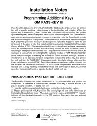
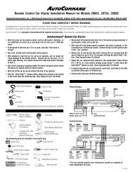
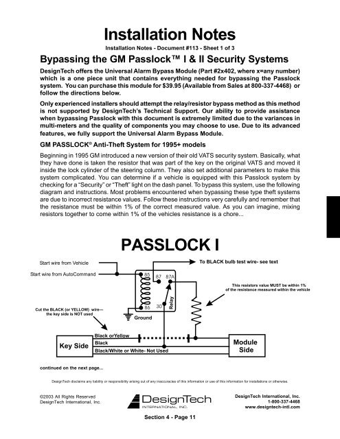
<strong>Installation</strong> <strong>Notes</strong><strong>Installation</strong> <strong>Notes</strong> - Document #113 - Sheet 1 of 3Bypassing the GM Passlock I & II Security SystemsDesignTech offers the Universal Alarm Bypass Module (Part #2x402, where x=any number)which is a one piece unit that contains everything needed for bypassing the Passlocksystem. You can purchase this module for $39.95 (Available from Sales at 800-337-4468) orfollow the directions below.Only experienced installers should attempt the relay/resistor bypass method as this methodis not supported by DesignTech’s Technical Support. Our ability to provide assistancewhen bypassing Passlock with this document is extremely limited due to the variances inmulti-meters and the quality of components you may choose to use. Due to its advancedfeatures, we fully support the Universal Alarm Bypass Module.GM <strong>PASSLOCK</strong> ® Anti-Theft System for 1995+ modelsBeginning in 1995 GM introduced a new version of their old VATS security system. Basically, whatthey have done is taken the resistor that was part of the key on the original VATS and moved itinside the lock cylinder of the steering column. They also set additional parameters to make thissystem complicated. You can determine if a vehicle is equipped with this Passlock system bychecking for a “Security” or “Theft” light on the dash panel. To bypass this system, use the followingdiagram and instructions. Most problems encountered when bypassing these type theft systemsare due to incorrect resistance values. Follow these instructions very carefully and remember thatthe resistance must be within 1% of the correct measured value. As you can imagine, mixingresistors together to come within 1% of the vehicles resistance is a chore...<strong>PASSLOCK</strong> Icontinued on the next page...DesignTech disclaims any liability or responsibility arising out of any inaccuracies of this information or use of this information for installations or otherwise.©2003 All Rights ReservedDesignTech International, Inc.DesignTech International, Inc.1-800-337-4468www.designtech-intl.comSection 4 - Page 11
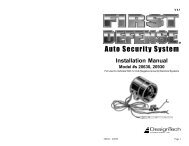
<strong>Installation</strong> <strong>Notes</strong><strong>Installation</strong> <strong>Notes</strong> - Document #113 - Sheet 2 of 3(Continued from previous page...)1. Remove the top and bottom halves of the steering column shroud.2. Locate the small three wire harness (with White, Black and Yellow wires) running down fromthe ignition key cylinder on the top right hand side of the steering column into the instrumentpanel.3. Cut the Yellow wire in half and bare back the Black wire.4. With the ignition key in and turned to the “ON” or “RUN” position, measure the resistancebetween the key side of the Yellow wire and the Black wire. Make several measurements toverify that you have a consistent resistance. You also need to change your test leads around.You will find that you get two different readings. We have found that in most cases the higherof the two readings is the correct resistance.5. When you have correctly identified the correct resistance obtain a resistance of the samevalue.6. Locate the Black “Bulb Test” wire on the left side of the steering column in cavity “D” or “E” ofthe Black 5-way connector, just above the main ignition switch connector.7. Wire your relay and resistor as shown in the diagram on the previous page.GM <strong>PASSLOCK</strong> ® II Anti-Theft System1997+ Malibu/Cutlass, 1998+ Oldsmobile Intrigue, Alero, Buick Regal, 1999 Pontiac Grand Amand all 1998+ truck platforms (Full size Pickup, Suburban, S-10/Sonoma, Blazer/Jimmy, Tahoe/Yukon and Astro/Safari) came out with the new Passlock II system. This system differs fromthat of <strong>PASSLOCK</strong> I and therefore needs to be wired differently utilizing the instructions and thediagram below.DesignTech offers the Universal Alarm Bypass Module (Part #20402) which has all theparts and materials necessary for bypassing this type of theft system. You can purchasethis module for $39.95 or follow the directions below.1. Remove the top and bottom halves of the steering column shroud.2. Locate the small three-wire harnesses (with Red/White, Orange/Black and Yellow wires) thatcome off of the ignition key.3. Cut the Yellow wire in half and bare back the Orange/Black wire.4. With the ignition key in and turned to the “ON” or “Run” position put the vehicle into reverse.continued on the next page...DesignTech disclaims any liability or responsibility arising out of any inaccuracies of this information or use of this information for installations or otherwise.©2003 All Rights ReservedDesignTech International, Inc.DesignTech International, Inc.1-800-337-4468www.designtech-intl.comSection 4 - Page 12
Continued from previous page<strong>Installation</strong> <strong>Notes</strong><strong>Installation</strong> <strong>Notes</strong> - Document #113 - Sheet 3 of 35. Turn the key to the “Start” position and release it to the “Run” position- Then measure theresistance between the key side of the cut Yellow wire and the Orange/Black wire.6. When you have correctly identified the correct resistance obtain a resistance of the samevalue.7. Wire relay and resistor as shown in the diagram below. The engine side of the Yellow wire willnot be used.Note: If you cannot obtain a resistance value, reconnect the Yellow wire and start the vehicle with thekey. Allow the ignition lights to normalize. Shut the vehicle off, separate the Yellow wire and follow steps4 – 7 again. To prevent the vehicle from entering “Tamper Mode” DO NOT attempt to crank the vehicle withthe yellow wire seperated. If you still cannot obtain a resistance reading you will need to try a differentdigital meter. (Analog meters do not have a high enough resolution to work) or see our website FAQ titled“Alternate Measure Passlock.”Note that the Yellow wire for the Passlock is a similar gauge wire to the Starter wire.Most problems encountered when bypassing these theft systems are due to incorrect resistancevalues. Again, You must acquire a resistor value within 1% of the value measured, which mayrequire mixing and matching of resistors. Some vehicles appear to have an even smaller tolerance,making this task rather difficult...The Malibu/Cutlass have different colors. Substitute as follows:Red/White = WhiteYellow = YellowOrange/Black = BlackWhite Ignition Wire = Dark Green<strong>PASSLOCK</strong> IIDesignTech disclaims any liability or responsibility arising out of any inaccuracies of this information or use of this information for installations or otherwise.©2003 All Rights ReservedDesignTech International, Inc.DesignTech International, Inc.1-800-337-4468www.designtech-intl.comSection 4 - Page 13