ACME Governor MAN B&W 9K90MC-VI - Laboratory of Marine ...
ACME Governor MAN B&W 9K90MC-VI - Laboratory of Marine ...
ACME Governor MAN B&W 9K90MC-VI - Laboratory of Marine ...

Create successful ePaper yourself
Turn your PDF publications into a flip-book with our unique Google optimized e-Paper software.
ADAPTIVE CONTROL OF MARINE ENGINES<br />
BRITE-EURAM CT95-0091 - STARTING DATE: 1.1.1996<br />
DG XII Scientific Officer: F. Sgarbi (E. Campogrande)<br />
<strong>ACME</strong><br />
FINAL PROJECT MEETING<br />
ATHENS, 24 FEBRUARY 2000
Outline <strong>of</strong> presentation<br />
• PART 1: Introduction and background<br />
• PART 2: The Consortium<br />
• PART 3: Project outline<br />
• PART 4: Technical achievements<br />
• PART 5: Conclusions and exploitation plan<br />
FINAL PROJECT MEETING, ATHENS 24 FEBRUARY 2000
PART 1<br />
INTRODUCTION AND BACKGROUND<br />
FINAL PROJECT MEETING, ATHENS 24 FEBRUARY 2000
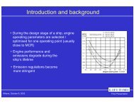
Introduction - State-<strong>of</strong>-art<br />
<strong>Marine</strong> propulsion propulsion units for new new ships ships are specified specified<br />
relying relying on power requirements for for calm calm water ship<br />
resistance adding empirical “service” “service” margins margins for<br />
actual operation<br />
Ship delivery trials are are also conducted conducted in calm<br />
waters waters<br />
Propulsion system is loaded <strong>of</strong>f-design point under<br />
transient conditions on the first voyage in heavy<br />
weather
Background - Pre-<strong>ACME</strong> history<br />
1994: DANAOS containership accident in the Pacific<br />
DANAOS requested the advise <strong>of</strong> NTUA/LME for<br />
operation <strong>of</strong> the ship powerplant in extreme conditions<br />
Extended discussions with the engine manufacturer<br />
<strong>MAN</strong>-B&W<br />
Consortium formed with the required expertise to<br />
study the problem
PART 2<br />
THE CONSORTIUM<br />
FINAL PROJECT MEETING, ATHENS 24 FEBRUARY 2000
The <strong>ACME</strong> Consortium<br />
Danaos Shipping Co. Ltd.<br />
<strong>MAN</strong>-B&W Diesel A/S<br />
ABB A/S<br />
HSVA GmbH<br />
LIPS B.V.<br />
Hapag Lloyd Linie GmbH<br />
NTUA
PART 3<br />
PROJECT OUTLINE<br />
FINAL PROJECT MEETING, ATHENS 24 FEBRUARY 2000
Objectives<br />
To develop methods based on mathematical modelling<br />
and process simulation, enabling to examine the<br />
dynamic behaviour <strong>of</strong> the propulsion installation in<br />
advance, during the ship design stage<br />
To develop engine adaptive control schemes and<br />
governor algorithms allowing maximum exploitation<br />
<strong>of</strong> powerplant capabilities in all ship operating<br />
conditions<br />
To verify verify the proposed methods and schemes by<br />
full-scale ship-board testing
Approach<br />
To consider the dynamic behaviour <strong>of</strong> all all the units<br />
in the propulsion system and especially the intimate<br />
coupling <strong>of</strong> the propeller-engine-turbocharger units<br />
Methodology<br />
1. Systematic self propulsion<br />
<strong>Governor</strong><br />
Propeller<br />
ship model tests inTurbocharger waves<br />
2. Propeller transient behaviour model<br />
3. Simulation <strong>of</strong> engine<br />
dynamic/thermodynamic behaviour<br />
?<br />
4. Control schemes<br />
5. Prototype and Engine full-scale<br />
testing
Work Packages<br />
W.P.1 Specification and Detailed Planning<br />
W.P.2 Model Tank Tests and Analysis<br />
W.P.3 Propeller Transient Behaviour Model<br />
W.P.4 Engine Dynamic Loading Predictions<br />
W.P.5 Propulsion System Simulation<br />
W.P.6 Definition <strong>of</strong> Adaptive Control Options<br />
W.P.7 Test-Bed Evaluation <strong>of</strong> Control Schemes<br />
W.P.8 On Board Installation and Trials<br />
W.P.9 Full Scale Sea-Passage Tests<br />
W.P.10 Analysis <strong>of</strong> Results-Recommendations
Work Packages<br />
<strong>ACME</strong> PROJECT CALENDAR<br />
YEAR 1- 1996 YEAR 2 - 1997 YEAR 3 - 1998 YEAR 4 - 1999 PARTNERS<br />
M onth nr. 1 2 3 4 5 6 7 8 9 10 11 12 1 2 3 4 5 6 7 8 9 10 11 12 1 2 3 4 5 6 7 8 9 10 11 12 1 2 3 4 5 6 7 8 9 10<br />
1 2 3 4 5 6 7 8 9 10 11 12 13 14 15 16 17 18 19 20 21 22 23 24 25 26 27 28 29 30 31 32 33 34 35 36 37 38 39 40 41 42 43 44 45 46<br />
Work Package WP M anager<br />
1. PLANNING NTUA<br />
2. M ODEL TANK TESTS HSVA<br />
3. PROPELLER M ODEL LIPS<br />
4. ENGINE DYNAM I CS M AN-B& W<br />
5. PROPULSION SI M ULATION NTUA<br />
6. CONTROL SCHEM ES M AN-B& W<br />
7. TEST BED TRIALS M AN-B& W<br />
8. ON BOARD INST. & TRIAL HAPAG-LLOYD<br />
9. FULL SEA TRI ALS HAPAG-LLOYD<br />
10. RECOM M ENDATIONS NTUA
PART 4<br />
TECHNICAL<br />
ACHIEVEMENTS<br />
FINAL PROJECT MEETING, ATHENS 24 FEBRUARY 2000
WORK PACKAGE 1<br />
SPECIFICATION AND DETAILED PLANNING<br />
WP <strong>MAN</strong>AGER<br />
FINAL PROJECT MEETING, ATHENS 24 FEBRUARY 2000
WORK PACKAGE 2<br />
MODEL TANK TESTS AND ANALYSIS<br />
WP <strong>MAN</strong>AGER<br />
FINAL PROJECT MEETING, ATHENS 24 FEBRUARY 2000
Objective<br />
To determine determine the propeller torque demand variations<br />
in regular and and irregular waves, in head and following seas<br />
Procedure<br />
Open water tests in calm water<br />
Open water tests in waves<br />
Nominal wake measurements in waves<br />
Self-propulsion tests in regular waves<br />
Self-propulsion tests in irregular head and following seas
Open water tests<br />
Self-propulsion tests
Open water tests<br />
Self-propulsion tests
Video <strong>of</strong> tank test measurements
WORK PACKAGE 3<br />
PROPELLER TRANSIENT BEHA<strong>VI</strong>OUR MODEL<br />
WP <strong>MAN</strong>AGER<br />
FINAL PROJECT MEETING, ATHENS 24 FEBRUARY 2000
Objective<br />
• To predict the propeller torque demand a few seconds<br />
ahead <strong>of</strong> time<br />
Procedure<br />
• Observation <strong>of</strong> correlation between maximum <strong>of</strong> aft<br />
vertical acceleration and minimum in propeller torque<br />
demand from HSVA experiments.<br />
• Based on HSVA measurements, develop a simple<br />
model for the prediction <strong>of</strong> propeller torque demand
Analytical model (LIPS)<br />
Input:<br />
Geometry <strong>of</strong> submerged blade and<br />
detailed wake distribution<br />
Geometry <strong>of</strong> the partially emerged blade<br />
The aim <strong>of</strong> the research <strong>of</strong> LIPS was to model the partial<br />
submergence problem with the aid PUF-3a <strong>of</strong> numerical code lifting<br />
surface theory in order to predict:<br />
Empirical • Unsteady model blade forces (HSVA)<br />
• Thrust<br />
• Torque<br />
Model is computationally<br />
demanding and input data<br />
difficult to obtain at full-scale<br />
irregular sea conditions<br />
Statistical model (NTUA)
Torque prediction method<br />
Analytical model (LIPS)<br />
Input:<br />
• Continuously measured torque<br />
• Propeller speed<br />
• Propeller relative motion<br />
Empirical Output: model (HSVA)<br />
•Torque approx. 1 sec ahead in time<br />
Statistical NOTE: model (NTUA)<br />
• Accurate prediction <strong>of</strong> the relative<br />
motion <strong>of</strong> the propeller is essential
• Head Seas<br />
Analytical model (LIPS)<br />
-3,0<br />
-4,0<br />
Empirical model (HSVA)<br />
-5,0<br />
-1,0<br />
Statistical model (NTUA)<br />
-3,0<br />
Vertical acceleration aft.<br />
(m/s^2)<br />
5,0<br />
3,0<br />
1,0<br />
-5,0<br />
-7,0<br />
5,0<br />
4,0<br />
3,0<br />
2,0<br />
1,0<br />
0,0<br />
0,5<br />
150<br />
-1,0<br />
155 160 165 170 175 180 185 190 195 200<br />
0,4<br />
-2,0<br />
t (sec)<br />
1,0<br />
0,9<br />
0,8<br />
0,7<br />
0,6<br />
0,3<br />
0,2<br />
0,1<br />
Torque coefficient*10<br />
0,0<br />
AcAf (m/s2)<br />
10*Kq<br />
170 175 180 185 190 195 200 205 210 215 2200,5<br />
t (sec)<br />
1,0<br />
0,9<br />
0,8<br />
0,7<br />
0,6<br />
0,4<br />
0,3<br />
0,2<br />
0,1<br />
0,0<br />
AcAf (m/s2)<br />
10*Kq
4000<br />
3500<br />
Q(kNt*m)<br />
Acceleration<br />
amplitude<br />
3000<br />
2500<br />
2000<br />
1500<br />
1000<br />
A Model output: Torque prediction<br />
Torque QA<br />
Max. acceleration<br />
t<br />
tB-delay<br />
tC-delay<br />
tD-delay<br />
Torque QB<br />
B<br />
Torque QC<br />
C<br />
Torque QD<br />
D<br />
Propeller<br />
Torque<br />
Demand<br />
approx. 4-8 sec ahead in time<br />
Vertical<br />
Acceleration<br />
time<br />
Events<br />
Model input: Aft vertical acceleration, Torque and Torque slope<br />
• Torque increases to a<br />
max value QB at tB • Torque decreases Series2 to a<br />
min value QC at tC • Torque returns to a<br />
value Q D at t D , where<br />
the next acceleration<br />
max occur<br />
100 200 300 400 500 600 700<br />
t(sec)<br />
Series1
Acceleration unit testing<br />
Objective<br />
• To calibrate the acceleration unit by on-board ship tests<br />
Procedure<br />
• Use an accelerometer hooked to a portable PC and record<br />
measurements <strong>of</strong> hull aft vertical acceleration<br />
• Test arrangement on a model ship
Planned on-board installation
On-board measurements<br />
Input signals:<br />
• Propeller shaft torque<br />
• Propeller shaft speed<br />
• Aft vertical acceleration<br />
Signal processing and torque<br />
prediction algorithm<br />
Output signal:<br />
• Torque demand approx.<br />
4-8 sec ahead in time
A1<br />
Torque/Power Meter<br />
Vertical<br />
Acceleration<br />
A: INPUT SIGNALS<br />
A2<br />
On-board measurements<br />
DAQ<br />
S<strong>of</strong>tware<br />
Propeller<br />
Model<br />
B: PROCESSING BOARD<br />
Torque<br />
Demand<br />
C: OUTPUT
1<br />
0<br />
-1<br />
3500<br />
3000<br />
2500<br />
Vertical Acceleration<br />
2000<br />
0 30 60<br />
30<br />
Torque<br />
60<br />
2800<br />
2750<br />
2700<br />
2650<br />
2600<br />
2550<br />
2500<br />
2450<br />
2800<br />
2750<br />
2700<br />
2650<br />
TORQUE PREDICTION 6 SEC<br />
TORQUE PREDICTION 10 SEC<br />
2600<br />
30 32 34 36 38 40<br />
2400<br />
50 52 54 56 58 60
Hardware:<br />
• Kistler K-Beam 8304A2 Capacitive Accelerometer<br />
• Accelerometer Interface Kistler 1572<br />
• Signal Terminal Box<br />
• Portable PC with DAQ board (NI DAQCard-700)<br />
S<strong>of</strong>tware:<br />
• In-house LABView based
Video <strong>of</strong> acceleration measurements
WORK PACKAGE 4<br />
ENGINE DYNAMIC LOADING PREDICTIONS<br />
WP <strong>MAN</strong>AGER<br />
FINAL PROJECT MEETING, ATHENS 24 FEBRUARY 2000
Turbocharger: ABB VTR 714
Compressor surge model<br />
extended compressor characteristic<br />
deep surge<br />
pressure<br />
ratio<br />
mild surge<br />
surge line<br />
• Unsteady flow compressor model developed<br />
• Implemented in the ABB simulation code (SiSy)<br />
• Further improvements needed<br />
mass<br />
flow
Video <strong>of</strong> compressor surge
WORK PACKAGE 5<br />
PROPULSION SYSTEM SIMULATION<br />
WP <strong>MAN</strong>AGER<br />
FINAL PROJECT MEETING, ATHENS 24 FEBRUARY 2000
Objective<br />
• To develop a model for the propulsion simulation in<br />
transient conditions (variable load) to be used in testing<br />
various engines control scenarios<br />
Procedure<br />
• Use the MoTher, TAPCODE and SiSy engine<br />
performance codes to perform steady-state simulation<br />
<strong>of</strong> the <strong>ACME</strong> engine<br />
• Tune sub-models where necessary<br />
• Develop control schemes based on simulation results<br />
• Perform engine transient simulations
<strong>MAN</strong>-B&W<br />
NTUA<br />
ABB<br />
MOTHER<br />
SiSy<br />
TAPCODE<br />
Load variation with high amplification<br />
and low damping. Compressor is surging !!
WORK PACKAGE 6<br />
DEFINITION OF ADAPTIVE CONTROL OPTIONS<br />
WP <strong>MAN</strong>AGER<br />
FINAL PROJECT MEETING, ATHENS 24 FEBRUARY 2000
Conventional Engine Layout<br />
TACHO<br />
PROPELLER<br />
LOAD<br />
NORD<br />
SPEED SETPOINT<br />
PI<br />
GOVERNOR<br />
<strong>9K90MC</strong><br />
FUEL INDEX PUMPS
Objective<br />
• To propose improved control scenarios also<br />
considering the propeller torque prediction availability<br />
Procedure<br />
• Identification <strong>of</strong> control issues<br />
• Investigation <strong>of</strong> possible control options through<br />
simulation
Control Schedule Test Environment<br />
Aft Ship Vertical<br />
Acceleration<br />
HSVA DATA<br />
Propeller Torque<br />
Coefficient, K Q<br />
PROPELLER<br />
MODEL<br />
Predicted Torque Demand<br />
~(t+5sec)<br />
Shaft Speed<br />
LOAD MODEL ENGINE MODEL<br />
Shaft Torque<br />
CONTROL<br />
SYSTEM<br />
Engine Status<br />
Engine<br />
Control
Control issues<br />
• Overspeed protection during fast load drops<br />
• Excessive speed during slow load fluctuation<br />
• Heavy running due to weak load variations<br />
• Compressor stall during acceleration <strong>of</strong> the<br />
propulsion plant
Overspeed protection<br />
•<br />
•<br />
Reduction Load<br />
Combination<br />
prediction <strong>of</strong> I-term<br />
<strong>of</strong><br />
feedforward<br />
the<br />
gain<br />
above<br />
for<br />
strategies<br />
positive acceleration<br />
for wider<br />
protection range<br />
Max Speed d<br />
Relative Kq, Engine Speed and Fuel Rack Position<br />
1.4<br />
Relative Kq, Engine Speed and Fuel Rack Position<br />
Max Speed 1.3 with Feed Forward<br />
Min Index with Feed Forward<br />
Gain <strong>of</strong> 40, 60 and 80% Speed<br />
Gain <strong>of</strong> 40, 60 and Rel. 80% Kq<br />
Rel. Speed(s)<br />
Rel. Kq<br />
1.2<br />
1.2<br />
110%<br />
1.1 1.07 1.07<br />
80%<br />
108%<br />
1<br />
1<br />
70%<br />
106%<br />
104%<br />
102%<br />
100%<br />
98%<br />
0<br />
0.8 0.9<br />
0.8<br />
0.6<br />
0.7<br />
Fuel Rack<br />
Position<br />
0.4 0.6<br />
Rel. Fuel Rack Position(s)<br />
20%<br />
0.5<br />
0.2<br />
0.4<br />
10%<br />
Rel. Kq<br />
Rel. Kq<br />
WITH High Speed Limiter<br />
WITHOUT<br />
WITH Load<br />
High<br />
Feed<br />
Speed<br />
Forward<br />
Limiter 0%<br />
WITHOUT Load Feed Forward<br />
0<br />
0.350<br />
Prediction 55 Time 60<br />
50 55 60<br />
65<br />
65<br />
70<br />
70<br />
75<br />
75<br />
Seconds<br />
Seconds<br />
80<br />
80<br />
85Prediction 90 Time 95<br />
85 90 95<br />
100<br />
100<br />
0.1<br />
0.2<br />
0.3<br />
0.4<br />
0.5<br />
1<br />
Min INdex<br />
60%<br />
50%<br />
40%<br />
30%<br />
0<br />
0.1<br />
0.2<br />
0.3<br />
0.4<br />
0.5<br />
1
Control issues<br />
• Overspeed protection during fast load drops<br />
• Excessive speed during slow load fluctuation<br />
• Heavy running due to weak load variations<br />
• Compressor stall during acceleration <strong>of</strong> the<br />
propulsion plant
Excessive speed<br />
• Adaptive speed setpoint<br />
1.03<br />
1.02<br />
1.01<br />
1<br />
0.99<br />
0.98<br />
0.97<br />
0.96<br />
0.95<br />
0.94<br />
Rel. Speed WITH Adaptive Setpoint<br />
Rel. Effective Speed Setpoint<br />
Rel. Speed WITHOUT Adaptive Setpoint<br />
0.93<br />
0 50 100 150<br />
Seconds<br />
200 250
Control issues<br />
• Overspeed protection during fast load drops<br />
• Excessive speed during slow load fluctuation<br />
• Heavy running due to weak load variations<br />
• Compressor stall during acceleration <strong>of</strong> the<br />
propulsion plant
Heavy running<br />
• Raised fuel index limiters in combination with s<strong>of</strong>t<br />
limiters for speed setpoint conditioning<br />
1<br />
0.9<br />
0.8<br />
0.7<br />
0.6<br />
Rel. Speed<br />
Rel. Fuel Index<br />
WITH Algorithm<br />
0.5<br />
0 50 100 150 200 250 300<br />
1<br />
0.9<br />
0.8<br />
0.7<br />
0.6<br />
Rel. Speed<br />
Rel. Fuel Index<br />
WITHOUT Algorithm<br />
0.5<br />
0 50 100 150<br />
Seconds<br />
200 250 300
Control issues<br />
• Overspeed protection during fast load drops<br />
• Excessive speed during slow load fluctuation<br />
• Heavy running due to weak load variations<br />
• Compressor stall during acceleration <strong>of</strong> the<br />
propulsion plant
Turbocharger<br />
• Fuel index gradient limiter as a function <strong>of</strong> outlet<br />
temperature time derivative<br />
• Speed Significant setpoint load increase fluctuation<br />
1.3 1.4<br />
1.2<br />
1.2<br />
1.1<br />
1<br />
1<br />
0.9<br />
0.8<br />
0.8<br />
0.6<br />
0.7<br />
0.4<br />
0.6<br />
0.2<br />
0.5<br />
Relative Kq, Engine Speed and Fuel Rack Position<br />
Compr. Flow / Compr. Flow on Surge Compr. Line Flow / Compr. Flow on Surge Line<br />
Fuel Rack<br />
Position<br />
Rel. Kq<br />
Speed<br />
Rel. Fuel KqRack<br />
Speed Setpoint<br />
WITH Position Surging Protection WITH Surging Protection<br />
WITHOUT Surging Protection WITHOUT Surging Protection<br />
0.40<br />
1550 55 2060 65 2570 75<br />
Seconds<br />
3080 85 3590 95 40 100
Torque Prediction Based Control<br />
Schemes<br />
• Generic optimal control scheme using performance<br />
indices including load tracking<br />
• Preventive Control Action that adjusts speed setpoint<br />
to avoid excessive overspeed
Optimal control<br />
Choice <strong>of</strong> desired cost function<br />
(including speed error and fuel index displacement)<br />
Solution <strong>of</strong> constrained optimization problem<br />
(system dynamics)<br />
Calculation <strong>of</strong> full fuel index schedule<br />
for the prediction time interval
Torque Prediction Based Control<br />
Schemes<br />
• Generic optimal control scheme using performance<br />
indices including load tracking<br />
• Preventive Control Action that adjusts speed setpoint<br />
to avoid excessive overspeed
Preventive control<br />
Propulsion system dynamics<br />
(Expected max. overspeed) α (Expected max. undertorque)<br />
Calculation <strong>of</strong> “safe” fuel index value
Simulation <strong>of</strong> control schedules<br />
TACHO<br />
ESPD2<br />
PROPELLER<br />
LOAD<br />
ESPD<br />
SPEED NORD<br />
SETPOINT<br />
ESPD1<br />
PI<br />
GOVERNOR<br />
RPM LIMITER<br />
SCAVENGING LIMITER<br />
FUEL RACK LIMITER<br />
LIMITER BLOCK<br />
AND DEAD BANDS<br />
••ORDERED ORDERED SPEED: SPEED: 89.0 89.0 RPM RPM<br />
••INITIAL INITIAL FUEL FUEL RACK RACK POSITION: POSITION: 0.85<br />
0.85<br />
<strong>9K90MC</strong><br />
ACTUATOR<br />
FUEL INDEX PUMPS
CONTROL STRATEGY<br />
• PI controller<br />
• Adjustable P and I gains dependent on the engine<br />
speed error range interval<br />
• Control action gain discrimination dependent on<br />
the sign <strong>of</strong> the differential<br />
CONTROL STRATEGY WITH<br />
engine speed error<br />
PREVENTIVE ACTION<br />
• Linear overspeed penalty function<br />
• Superimpose knowledge <strong>of</strong> the<br />
• Engine speed and scavenging limiters<br />
propeller future torque demand<br />
• Low-pass filtering <strong>of</strong> the required speed command<br />
on the controller actions, to avoid<br />
signal<br />
engine overspeeds and generate<br />
smoother rack movements
SIMULATIONS<br />
• Fixed rack position 0.85<br />
• PI controller without torque prediction<br />
• PI controller with torque prediction<br />
• Clean vs. “dirty” compressor<br />
ENGINE LOAD (taken from HSVA data)<br />
10 Kq<br />
0.6<br />
0.5<br />
0.4<br />
0.3<br />
0.2<br />
0 10 20 30 40 50 60 70 80 90 100<br />
Time ( sec )<br />
10Kq variation used for the simulation tests
Engine Speed (RPM)<br />
Torque (KN m)<br />
105<br />
100<br />
95<br />
90<br />
85<br />
80<br />
4500<br />
4000<br />
3500<br />
3000<br />
2500<br />
2000<br />
1500<br />
1000<br />
Propeller<br />
Engine<br />
0 10 20 30 40 50 60 70 80 90 100<br />
Time (sec)<br />
Variation <strong>of</strong> engine speed and torque and load torque (fixed rack position at 0.85)<br />
Compressor map (fixed rack position at 0.85)<br />
Pressure Ratio<br />
Fixed rack position 0.85<br />
4.5<br />
4.0<br />
3.5<br />
3.0<br />
2.5<br />
2.0<br />
1.5<br />
1.0<br />
5 10 15 20 25 30 35<br />
Corrected air volumetric flow rate (m^3/s)
Rack Position<br />
Engine Speed (RPM)<br />
Torque (KN m)<br />
1.0<br />
0.9<br />
0.8<br />
0.7<br />
0.6<br />
0.5<br />
0.4<br />
0.3<br />
0.2<br />
105<br />
100<br />
95<br />
90<br />
85<br />
80<br />
4500<br />
4000<br />
3500<br />
3000<br />
2500<br />
2000<br />
1500<br />
1000<br />
Propeller<br />
Engine<br />
0 10 20 30 40 50 60 70 80 90 100<br />
Time (sec)<br />
Simulation Results (PI control without load prediction)<br />
PI controller without torque prediction<br />
Pressure Ratio<br />
4.5<br />
4.0<br />
3.5<br />
3.0<br />
2.5<br />
2.0<br />
1.5<br />
1.0<br />
5 10 15 20 25 30 35<br />
Corrected air volumetric flow rate (m^3/s)<br />
Compressor map (PI control)
Rack Position<br />
Engine Speed (RPM)<br />
Torque (KN m)<br />
1.0<br />
0.9<br />
0.8<br />
0.7<br />
0.6<br />
0.5<br />
0.4<br />
0.3<br />
0.2<br />
105<br />
100<br />
95<br />
90<br />
85<br />
80<br />
4500<br />
4000<br />
3500<br />
3000<br />
2500<br />
2000<br />
1500<br />
1000<br />
Propeller<br />
Engine<br />
0 10 20 30 40 50 60 70 80 90 100<br />
Time (sec)<br />
Simulation Results (PI control with load prediction)<br />
PI controller with torque prediction<br />
Pressure Ratio<br />
4.5<br />
4.0<br />
3.5<br />
3.0<br />
2.5<br />
2.0<br />
1.5<br />
1.0<br />
5 10 15 20 25 30 35<br />
Corrected air volumetric flow rate (m^3/s)<br />
Compressor map (PI control with load prediction)
Mass Flow Rate (kg/s)<br />
T/C Speed ( RPM )<br />
Rack Position<br />
Engine Speed (RPM)<br />
Torque (KN m)<br />
40<br />
35<br />
30<br />
25<br />
20<br />
12000<br />
11000<br />
10000<br />
9000<br />
1.0<br />
0.9<br />
0.8<br />
0.7<br />
0.6<br />
0.5<br />
0.4<br />
0.3<br />
0.2<br />
105<br />
100<br />
95<br />
90<br />
85<br />
80<br />
4500<br />
4000<br />
3500<br />
3000<br />
2500<br />
2000<br />
1500<br />
1000<br />
Clean Compressor<br />
Dirty Compressor<br />
Clean Compressor<br />
Dirty Compressor<br />
0 10 20 30 40 50 60 70 80 90 100<br />
Time (sec)<br />
Propeller<br />
Engine<br />
0 10 20 30 40 50 60 70 80 90 100<br />
Time (sec)<br />
Clean vs. “dirty” compressor<br />
Pressure Ratio<br />
Pressure Ratio<br />
4.5<br />
4.0<br />
3.5<br />
3.0<br />
2.5<br />
2.0<br />
1.5<br />
1.0<br />
4.5<br />
4.0<br />
3.5<br />
3.0<br />
2.5<br />
2.0<br />
1.5<br />
1.0<br />
5 10 15 20 25 30 35<br />
Corrected air volumetric flow rate (m^3/s)<br />
5 10 15 20 25 30 35<br />
Corrected air volumetric flow rate (m^3/s)
Evaluation <strong>of</strong> results<br />
• Sensitive PI governor results to small engine speed<br />
fluctuation<br />
• Speed setpoint adjustment adaptation<br />
• Determination <strong>of</strong> unique set <strong>of</strong> constants for the PI<br />
governor<br />
• Proper utilization <strong>of</strong> propeller torque prediction can lead<br />
to a reduction <strong>of</strong> overspeed risk in near MCR engine<br />
operation
Project Mid-term<br />
Handling <strong>of</strong> ‘management crises’<br />
Redestribution Withdrawal <strong>of</strong> <strong>of</strong> budget from to cover the consortium engineering in installation month 18, and<br />
electrical following Cancellation Four joined month work completion<br />
the<br />
<strong>of</strong> to project the be<br />
consortium<br />
performed <strong>of</strong> extension WP3,<br />
from<br />
due newbuilding on-board to to<br />
month accommodate internal the<br />
18<br />
due Hapag-Lloyd<br />
<strong>of</strong>fering<br />
staffing to Gdansk vessel a similar<br />
containership<br />
containership<br />
problems. shipyard schedule bankruptsy Remaining (Third ‘Shanghai<br />
for on-board Contract peripheral Express’<br />
tests Amendment (First<br />
by work STN<br />
Contract<br />
redistributed April Atlas 1999). Elektronik<br />
Amendment<br />
within<br />
(Second<br />
September<br />
the consortium Contract<br />
1997).<br />
and Amendment related task November fully completed 1998). as planned<br />
(First Contract Amendment September 1997).
Engine and shipbuilding
<strong>MAN</strong> B&W <strong>9K90MC</strong> engine<br />
Power: 55980 Bhp<br />
94 RPM<br />
Pmax: 141 bar<br />
PE: 18 bar<br />
SFOC: 128g/Bhph<br />
SHANGHAI EXPRESS<br />
4600 TEU Container Vessel<br />
Length: 281.6 m<br />
Breadth: 32.5 m<br />
Deadweight: 66771 MT<br />
Service speed: 24 kts
<strong>9K90MC</strong> - SHOP TEST<br />
Verification <strong>of</strong>:<br />
• Engine Performance<br />
• SFOC<br />
• Turbocharger performance<br />
• Turbocharger efficiency<br />
• Thermal load on engine<br />
• IMO Regulations<br />
Atomizers tested for:<br />
• Minimum thermal load on engine<br />
• Fuel optimization<br />
• NOx optimization for expected<br />
IMO regulation
Video <strong>of</strong> shop trials
WORK PACKAGE 7<br />
TEST-BED EVALUATION OF CONTROL SCHEMES<br />
WP <strong>MAN</strong>AGER<br />
FINAL PROJECT MEETING, ATHENS 24 FEBRUARY 2000
Objectives<br />
To design the <strong>ACME</strong> governor through simulation <strong>of</strong><br />
the complete propulsion system under rapidly varying<br />
load (heavy weather conditions)
Control system integration<br />
<strong>ACME</strong><br />
<strong>Governor</strong><br />
Existing<br />
<strong>Governor</strong><br />
<strong>MAN</strong> B&W<br />
<strong>9K90MC</strong>-<strong>VI</strong>
The <strong>ACME</strong> <strong>Governor</strong><br />
Hardware platform specifically developed by <strong>MAN</strong> B&W for<br />
marine use<br />
• CPU 32-bit 16MHz Motorola 68332 microprocessor<br />
• Built-in Time Processing Unit (TPU) for speed tracking<br />
• Serial RS232/485 interface<br />
Embedded s<strong>of</strong>tware in two layers<br />
• Basic Electronic System (BES) incorporating the Real Time<br />
Operating System (RTXC)<br />
• Algorithms for main engine speed regulation
<strong>ACME</strong> governor integration<br />
L ˆ<br />
Existing<br />
<strong>Governor</strong><br />
PID<br />
Controller<br />
Prediction-based<br />
Controller<br />
TP System<br />
<strong>ACME</strong><br />
GOVERNOR<br />
y PID<br />
+<br />
y PBC<br />
y<br />
PROPULSION<br />
SYSTEM<br />
L<br />
N
Control system integration<br />
Aft Ship<br />
Acceleration<br />
I / F<br />
1<br />
S<br />
P<br />
U<br />
Shaft Speed<br />
Shaft Torque<br />
<strong>ACME</strong><br />
<strong>Governor</strong><br />
I / F<br />
2<br />
Existing<br />
<strong>Governor</strong><br />
<strong>MAN</strong> B&W<br />
<strong>9K90MC</strong>-<strong>VI</strong>
TP system functionality<br />
• Data acquisition<br />
• Data processing processing - Speed setpoint conditioning<br />
• Data logging logging - Database update
Control system integration<br />
Aft Ship<br />
Acceleration<br />
I / F<br />
1<br />
S<br />
P<br />
U<br />
Shaft Speed<br />
Shaft Torque<br />
<strong>ACME</strong><br />
<strong>Governor</strong><br />
I / F<br />
2<br />
Existing<br />
<strong>Governor</strong><br />
<strong>MAN</strong> B&W<br />
<strong>9K90MC</strong>-<strong>VI</strong>
TP system<br />
functional diagram<br />
Accelerometer<br />
AFT BULKHEAD<br />
KISTLER AID-4<br />
Vertical Ship<br />
Acceleration<br />
(analog, -/+2 V)<br />
INTERFACE<br />
MODULE 1<br />
SHAFTING<br />
SYSTEM<br />
Shaft<br />
Speed<br />
(analog,<br />
4-20 mA)<br />
HOPPE<br />
Torque/Power Meter<br />
Typ MIP<br />
RS-485<br />
Serial Link<br />
Shaft<br />
Torque<br />
(analog,<br />
4-20 mA)<br />
SIGNAL<br />
PROCESSING<br />
UNIT<br />
Industrial<br />
Single-board<br />
PC<br />
LOG<br />
Hard<br />
Disk<br />
Drive<br />
AID-4<br />
AC POWER SOURCE<br />
MAIN SWITCHBOARD ROOM<br />
INTERFACE MODULE 2<br />
Validation<br />
Signal<br />
(digital,<br />
0-24 V)<br />
Requested<br />
Fuel Rack<br />
Position<br />
(analog, 4-20 mA)<br />
RS-485<br />
Serial Link<br />
AID-4<br />
<strong>ACME</strong><br />
<strong>Governor</strong><br />
I / F<br />
1<br />
S<br />
P<br />
U<br />
Speed setpoint<br />
decrease rate<br />
(analog, 4-20 mA)<br />
<strong>ACME</strong><br />
<strong>Governor</strong><br />
Speed setpoint<br />
decrease rate<br />
Boost Pressure<br />
(analog, 4-20 mA )<br />
I / F<br />
2<br />
<strong>MAN</strong> B&W<br />
<strong>9K90MC</strong>-<strong>VI</strong><br />
Engine Speed setpoint<br />
(analog, 4-20 mA)<br />
Engine Fuel Rack Position<br />
(analog, 4-20 mA)<br />
Existing<br />
<strong>Governor</strong>
Signal processing unit (SPU)<br />
Hardware<br />
• Industrial single-board PC<br />
• CPU 5x86/133MHz<br />
• 4 Mbytes DRAM<br />
• 1.4 Gbytes hard disk<br />
S<strong>of</strong>tware<br />
• Embeddable version <strong>of</strong> the TP algorithm<br />
• DAQ, pre-processing and communications<br />
s<strong>of</strong>tware<br />
I / F<br />
1<br />
S<br />
P<br />
U<br />
<strong>ACME</strong><br />
<strong>Governor</strong><br />
I / F<br />
2<br />
<strong>MAN</strong> B&W<br />
<strong>9K90MC</strong>-<strong>VI</strong><br />
Existing<br />
<strong>Governor</strong>
DAQ and transmission<br />
system (AID-4)<br />
Hardware<br />
•CPU AT90S8515/11 MHz with watchdog timer<br />
• 512 Kbytes RAM<br />
S<strong>of</strong>tware<br />
•Programmable low pass filter and gain amplifier<br />
• DAQ and communications s<strong>of</strong>tware<br />
I / F<br />
1<br />
S<br />
P<br />
U<br />
<strong>ACME</strong><br />
<strong>Governor</strong><br />
I / F<br />
2<br />
<strong>MAN</strong> B&W<br />
<strong>9K90MC</strong>-<strong>VI</strong><br />
Existing<br />
<strong>Governor</strong>
Control system integration<br />
Aft Ship<br />
Acceleration<br />
I / F<br />
1<br />
S<br />
P<br />
U<br />
Shaft Speed<br />
Shaft Torque<br />
<strong>ACME</strong><br />
<strong>Governor</strong><br />
I / F<br />
2<br />
Existing<br />
<strong>Governor</strong><br />
<strong>MAN</strong> B&W<br />
<strong>9K90MC</strong>-<strong>VI</strong>
WORK PACKAGE 8<br />
ON BOARD INSTALLATION AND TRIALS<br />
WP <strong>MAN</strong>AGER<br />
FINAL PROJECT MEETING, ATHENS 24 FEBRUARY 2000
<strong>9K90MC</strong><br />
<strong>ACME</strong><br />
<strong>Governor</strong><br />
Torque<br />
Prediction<br />
System<br />
PASSIVE<br />
RECORDING<br />
PASSIVE<br />
RECORDING<br />
Scenario I<br />
<strong>9K90MC</strong><br />
<strong>ACME</strong><br />
<strong>Governor</strong><br />
Torque<br />
Prediction<br />
System<br />
PASSIVE<br />
RECORDING<br />
PASSIVE<br />
RECORDING<br />
Scenario I<br />
<strong>9K90MC</strong><br />
<strong>ACME</strong><br />
<strong>Governor</strong><br />
Torque<br />
Prediction<br />
System<br />
PASSIVE<br />
RECORDING<br />
PASSIVE<br />
RECORDING<br />
<strong>9K90MC</strong><br />
<strong>ACME</strong><br />
<strong>Governor</strong><br />
Torque<br />
Prediction<br />
System<br />
PASSIVE<br />
RECORDING<br />
PASSIVE<br />
RECORDING<br />
Scenario I<br />
<strong>9K90MC</strong><br />
<strong>ACME</strong><br />
<strong>Governor</strong><br />
Torque<br />
Prediction<br />
System<br />
PASSIVE<br />
RECORDING<br />
PASSIVE<br />
RECORDING<br />
ACTIVE<br />
INTERVENTION<br />
Scenario II<br />
<strong>9K90MC</strong><br />
<strong>ACME</strong><br />
<strong>Governor</strong><br />
Torque<br />
Prediction<br />
System<br />
PASSIVE<br />
RECORDING<br />
PASSIVE<br />
RECORDING<br />
ACTIVE<br />
INTERVENTION<br />
Scenario II<br />
Possible Installation Scenarios
Scenario III<br />
<strong>9K90MC</strong><br />
<strong>ACME</strong><br />
<strong>Governor</strong><br />
Torque<br />
Prediction<br />
System<br />
PASSIVE<br />
RECORDING<br />
PASSIVE<br />
RECORDING<br />
Scenario I<br />
<strong>9K90MC</strong><br />
<strong>ACME</strong><br />
<strong>Governor</strong><br />
Torque<br />
Prediction<br />
System<br />
PASSIVE<br />
RECORDING<br />
PASSIVE<br />
RECORDING<br />
<strong>9K90MC</strong><br />
<strong>ACME</strong><br />
<strong>Governor</strong><br />
Torque<br />
Prediction<br />
System<br />
PASSIVE<br />
RECORDING<br />
PASSIVE<br />
RECORDING<br />
Scenario I<br />
<strong>9K90MC</strong><br />
<strong>ACME</strong><br />
<strong>Governor</strong><br />
Torque<br />
Prediction<br />
System<br />
PASSIVE<br />
RECORDING<br />
PASSIVE<br />
RECORDING<br />
ACTIVE<br />
INTERVENTION<br />
Scenario II<br />
<strong>9K90MC</strong><br />
<strong>ACME</strong><br />
<strong>Governor</strong><br />
Torque<br />
Prediction<br />
System<br />
PASSIVE<br />
RECORDING<br />
PASSIVE<br />
RECORDING<br />
ACTIVE<br />
INTERVENTION<br />
Scenario IV<br />
<strong>9K90MC</strong><br />
<strong>ACME</strong><br />
<strong>Governor</strong><br />
Torque<br />
Prediction<br />
System<br />
PASSIVE<br />
RECORDING<br />
PASSIVE<br />
RECORDING<br />
<strong>9K90MC</strong><br />
<strong>ACME</strong><br />
<strong>Governor</strong><br />
Torque<br />
Prediction<br />
System<br />
PASSIVE<br />
RECORDING<br />
PASSIVE<br />
RECORDING<br />
ACTIVE<br />
INTERVENTION<br />
ACTIVE<br />
INTERVENTION<br />
Possible Installation Scenarios<br />
Scenario IV<br />
Selected Installation Scenarios<br />
<strong>9K90MC</strong><br />
<strong>ACME</strong><br />
<strong>Governor</strong><br />
Torque<br />
Prediction<br />
System<br />
PASSIVE<br />
RECORDING<br />
PASSIVE<br />
RECORDING<br />
<strong>9K90MC</strong><br />
<strong>ACME</strong><br />
<strong>Governor</strong><br />
Torque<br />
Prediction<br />
System<br />
PASSIVE<br />
RECORDING<br />
PASSIVE<br />
RECORDING<br />
ACTIVE<br />
INTERVENTION<br />
ACTIVE<br />
INTERVENTION<br />
Scenario III<br />
<strong>9K90MC</strong><br />
<strong>ACME</strong><br />
<strong>Governor</strong><br />
Torque<br />
Prediction<br />
System<br />
PASSIVE<br />
RECORDING<br />
PASSIVE<br />
RECORDING<br />
<strong>9K90MC</strong><br />
<strong>ACME</strong><br />
<strong>Governor</strong><br />
Torque<br />
Prediction<br />
System<br />
PASSIVE<br />
RECORDING<br />
PASSIVE<br />
RECORDING<br />
ACTIVE<br />
INTERVENTION<br />
ACTIVE<br />
INTERVENTION<br />
Scenario IV<br />
ACTIVE<br />
INTERVENTION
Control system integration<br />
Aft Ship<br />
Acceleration<br />
I / F<br />
1<br />
S<br />
P<br />
U<br />
Shaft Speed<br />
Shaft Torque<br />
<strong>ACME</strong><br />
<strong>Governor</strong><br />
I / F<br />
2<br />
Standard<br />
<strong>Governor</strong><br />
<strong>MAN</strong> B&W<br />
<strong>9K90MC</strong>-<strong>VI</strong>
STN installation drawings
I / F<br />
1<br />
S<br />
P<br />
U<br />
Interface Module 1:<br />
Data acquisition<br />
- Acceleration<br />
- Torque<br />
- (RPM)<br />
Shaft<br />
<strong>ACME</strong><br />
<strong>Governor</strong><br />
I / F<br />
2<br />
<strong>MAN</strong> B&W<br />
<strong>9K90MC</strong>-<strong>VI</strong><br />
Existing<br />
<strong>Governor</strong><br />
Aft bulkhead
I / F<br />
1<br />
Interface Module 2:<br />
S<br />
P<br />
U<br />
<strong>ACME</strong><br />
<strong>Governor</strong><br />
<strong>MAN</strong> B&W<br />
<strong>9K90MC</strong>-<strong>VI</strong><br />
Existing<br />
<strong>Governor</strong><br />
- Data acquisition/transmission<br />
Signal Processing Unit (SPU)<br />
I / F<br />
2<br />
- TP algorithm<br />
- Storage<br />
Main switchboard room<br />
TP system
I / F<br />
1<br />
Interface Module 2:<br />
S<br />
P<br />
U<br />
<strong>ACME</strong><br />
<strong>Governor</strong><br />
Data acquisition<br />
- Boost pressure<br />
- Actual fuel rack position<br />
- Engine speed setpoint<br />
- <strong>ACME</strong> governor rack setpoint<br />
Data transmission<br />
- Speed setpoint decrease rate<br />
- Validation signal<br />
Signal Processing Unit (SPU)<br />
- TP algorithm<br />
- Storage<br />
I / F<br />
2<br />
<strong>MAN</strong> B&W<br />
<strong>9K90MC</strong>-<strong>VI</strong><br />
Existing<br />
<strong>Governor</strong><br />
Main switchboard room<br />
TP system
Main switchboard room<br />
<strong>ACME</strong> governor<br />
I / F<br />
1<br />
S<br />
P<br />
U<br />
<strong>ACME</strong><br />
<strong>Governor</strong><br />
I / F<br />
2<br />
<strong>MAN</strong> B&W<br />
<strong>9K90MC</strong>-<strong>VI</strong><br />
Existing<br />
<strong>Governor</strong>
Engine room overview
WORK PACKAGE 9<br />
FULL SCALE SEA-PASSAGE TESTS<br />
WP <strong>MAN</strong>AGER<br />
FINAL PROJECT MEETING, ATHENS 24 FEBRUARY 2000
Shanghai Express route<br />
Antwerp<br />
Bremerhaven<br />
Port Said<br />
Hong Kong<br />
Singapore<br />
Pusan
Engine prototype system testing<br />
Main Engine
Engine prototype system testing<br />
Shaft tunnel
Shanghai Express route<br />
• Eight months total logging period with more than 90%<br />
unattended operation <strong>of</strong> the Data Acquisition system.<br />
• Total data logged amount to more than 3.5GB disk<br />
space in binary compressed format.
Objectives<br />
•• Acquire on-line measurements <strong>of</strong> both aft ship ship vertical<br />
acceleration and shaft torque and other engine variables<br />
• Determine speed setpoint decrease rate
Recorded variables<br />
Manual log<br />
Weather conditions - Sea condition<br />
Real time data acquisition<br />
Propeller shaft torque<br />
Propeller shaft speed<br />
Aft ship vertical acceleration<br />
Engine boost pressure<br />
Engine boost pressure<br />
Engine speed setpoint<br />
Requested fuel rack position<br />
Actual fuel rack position at fuel pump
Bridge video
-0.15<br />
Recorded variables<br />
Manual log<br />
-0.21<br />
Weather conditions - Sea condition<br />
Real time data acquisition<br />
-0.25<br />
Propeller shaft torque<br />
-0.27<br />
Propeller shaft speed<br />
1600.00<br />
1400.00<br />
Aft ship vertical acceleration<br />
1200.00<br />
Engine boost pressure<br />
1000.00<br />
Engine speed setpoint<br />
800.00<br />
Requested fuel rack position<br />
Acc. [m/sec 2 ]<br />
-0.17<br />
-0.19<br />
-0.23<br />
0.0<br />
8.8<br />
600.00<br />
Actual fuel rack position at fuel pump<br />
Torque [kN*m]<br />
17.6<br />
26.4<br />
400.00<br />
35.2<br />
44.0<br />
0.0<br />
9.2<br />
52.8<br />
18.4<br />
61.6<br />
70.4<br />
27.6<br />
Speed [RPM]<br />
36.8<br />
55.00<br />
50.00<br />
79.2<br />
88.0<br />
45.00<br />
40.00<br />
35.00<br />
30.00<br />
46.0<br />
55.2<br />
96.8<br />
105.6<br />
64.4<br />
114.4<br />
123.2<br />
73.6<br />
82.8<br />
92.0<br />
29-05-99<br />
11:45-11:50<br />
132.0<br />
140.8<br />
101.2<br />
149.6<br />
110.4<br />
158.4<br />
167.2<br />
Time [sec]<br />
119.6<br />
128.8<br />
29-05-99<br />
29-05-99 11:45-11:50<br />
11:45-11:50<br />
176.0<br />
184.8<br />
0.0<br />
8.4<br />
16.8<br />
25.2<br />
33.6<br />
42.0<br />
50.4<br />
58.8<br />
67.2<br />
75.6<br />
84.0<br />
92.4<br />
100.8<br />
109.2<br />
117.6<br />
126.0<br />
134.4<br />
142.8<br />
151.2<br />
159.6<br />
168.0<br />
176.4<br />
184.8<br />
193.2<br />
201.6<br />
210.0<br />
218.4<br />
226.8<br />
235.2<br />
243.6<br />
252.0<br />
260.4<br />
268.8<br />
277.2<br />
285.6<br />
294.0<br />
138.0<br />
147.2<br />
193.6<br />
202.4<br />
156.4<br />
Time [sec]<br />
Time [sec]<br />
165.6<br />
211.2<br />
220.0<br />
174.8<br />
184.0<br />
228.8<br />
237.6<br />
193.2<br />
202.4<br />
246.4<br />
255.2<br />
211.6<br />
220.8<br />
264.0<br />
272.8<br />
230.0<br />
239.2<br />
281.6<br />
290.4<br />
248.4<br />
257.6<br />
299.2<br />
266.8<br />
276.0<br />
Acc<br />
285.2<br />
294.4<br />
Speed<br />
Torque
Recorded variables<br />
1.18<br />
1.16<br />
56.00<br />
Manual log<br />
1.14<br />
29-05-99<br />
52.00 Weather conditions - Sea condition<br />
Fuel rack Requested [%] Fuel Setpoint Rack [%] speed Boost [%] pressure [bar]<br />
54.00<br />
59,00<br />
57,00<br />
1.12<br />
50.00<br />
52.00<br />
55,00<br />
48.00<br />
50.00<br />
1.10 Real time data acquisition<br />
46.00 53,00<br />
48.00<br />
1.08<br />
44.00 Propeller 51,00 shaft torque<br />
46.00<br />
42.00<br />
Propeller shaft speed<br />
1.06 44.00 49,00<br />
40.00<br />
Aft ship vertical acceleration<br />
0.0<br />
42.00<br />
47,00<br />
38.00<br />
8.8<br />
17.6<br />
26.4<br />
Engine 40.00 boost pressure<br />
45,00<br />
0.0<br />
38.00 Engine speed setpoint<br />
0,0<br />
8.6<br />
9,2<br />
0.0<br />
9.0<br />
17.2<br />
18,4<br />
25.8<br />
27,6<br />
18.0<br />
27.0<br />
35.2<br />
34.4<br />
36,8<br />
44.0<br />
43.0<br />
46,0<br />
36.0<br />
45.0<br />
52.8<br />
Requested fuel rack position<br />
51.6<br />
55,2<br />
61.6<br />
60.2<br />
64,4<br />
70.4<br />
54.0<br />
63.0<br />
68.8<br />
73,6<br />
79.2<br />
77.4<br />
82,8<br />
29-05-99<br />
11:45-11:50<br />
Actual fuel rack position at fuel pump<br />
88.0<br />
86.0<br />
72.0<br />
81.0<br />
92,0<br />
96.8<br />
105.6<br />
94.6<br />
103.2<br />
101,2<br />
110,4<br />
90.0<br />
99.0<br />
114.4<br />
123.2<br />
111.8<br />
120.4<br />
119,6<br />
128,8<br />
108.0<br />
117.0<br />
132.0<br />
29-05-99<br />
11:45-11:50<br />
140.8<br />
149.6<br />
129.0<br />
137.6<br />
29-05-99<br />
11:45-11:50<br />
158.4<br />
167.2<br />
Time [sec]<br />
138,0<br />
147,2<br />
146.2<br />
154.8<br />
Time [sec]<br />
156,4<br />
165,6<br />
Time [sec]<br />
126.0<br />
135.0<br />
11:45-11:50<br />
144.0<br />
153.0<br />
176.0<br />
184.8<br />
163.4<br />
172.0<br />
174,8<br />
184,0<br />
162.0<br />
Time [sec]<br />
180.6<br />
189.2<br />
193.6<br />
202.4<br />
193,2<br />
202,4<br />
171.0<br />
180.0<br />
197.8<br />
206.4<br />
211.2<br />
220.0<br />
211,6<br />
220,8<br />
189.0<br />
198.0<br />
215.0<br />
223.6<br />
228.8<br />
237.6<br />
230,0<br />
239,2<br />
207.0<br />
216.0<br />
232.2<br />
240.8<br />
246.4<br />
255.2<br />
248,4<br />
257,6<br />
225.0<br />
234.0<br />
249.4<br />
258.0<br />
264.0<br />
272.8<br />
266,8<br />
276,0<br />
243.0<br />
252.0<br />
266.6<br />
275.2<br />
281.6<br />
290.4<br />
285,2<br />
294,4<br />
261.0<br />
270.0<br />
299.2<br />
283.8<br />
292.4<br />
279.0<br />
288.0<br />
Boost pres.<br />
Setpoint<br />
Req. Fuel Rack<br />
297.0<br />
Fuel Rack
On board testing<br />
Main switchboard room video
Typical logged signal fragments<br />
Disk #1 24/2/1999 23:45 - 23:59<br />
Shaft Speed (rpm)<br />
Shaft Torque (kNm)<br />
95<br />
94<br />
93<br />
92<br />
91<br />
90<br />
3400<br />
3300<br />
3200<br />
3100<br />
0.5<br />
0.0<br />
-0.5<br />
-1.0<br />
Vertical Acc. (m/s/s) 3000<br />
Shaft Torque<br />
Shaft Speed<br />
Vertical Acceleration<br />
0 500 1000 1500 2000 2500 3000 3500 4000<br />
Sample Number
Typical logged signal fragments<br />
Disk #2 4/3/1999 17:00 - 17:15<br />
Shaft Speed (rpm)<br />
Shaft Torque (kNm)<br />
80<br />
79<br />
78<br />
77<br />
76<br />
75<br />
74<br />
3000<br />
2500<br />
2000<br />
0.3<br />
0.2<br />
0.1<br />
0.0<br />
-0.1<br />
-0.2<br />
-0.3<br />
-0.4<br />
-0.5<br />
1500<br />
Vertical Vertical Acc. (m/s/s)<br />
Shaft Torque<br />
Shaft Speed<br />
Vertical Acceleration<br />
0 500 1000 1500 2000 2500 3000 3500 4000<br />
Sample Number
Typical logged signal fragments<br />
Disk #3 4/5/1999 12:15 - 12:31<br />
Shaft Speed (rpm)<br />
Shaft Shaft Torque Torque (kNm) (kNm)<br />
Vertical Vertical Acc. (m/s/s)<br />
50<br />
45<br />
40<br />
35<br />
30<br />
25<br />
20<br />
15<br />
10<br />
5<br />
0<br />
1200<br />
1000<br />
800<br />
600<br />
400<br />
200<br />
0<br />
0.0<br />
-0.1<br />
-0.2<br />
Shaft Torque<br />
Shaft Speed<br />
Vertical Acceleration<br />
0 500 1000 1500 2000 2500 3000 3500 4000 4500<br />
Sample Number<br />
Reversal
Typical logged signal fragments<br />
Disk #3 4/5/1999 12:15 - 12:31<br />
Speed Setpoint (rpm)<br />
Fuel Rack (%)<br />
Boost Pressure (bar)<br />
55<br />
50<br />
45<br />
40<br />
35<br />
30<br />
25<br />
80<br />
70<br />
60<br />
50<br />
40<br />
30<br />
20<br />
10<br />
0<br />
1.2<br />
1.1<br />
Speed Setpoint<br />
Fuel Rack Position<br />
Boost Pressure<br />
0 500 1000 1500 2000 2500 3000 3500 4000 4500<br />
Sample Number<br />
Actual<br />
Requested
Typical logged signal fragments<br />
Disk #4 5/7/1999 23:35 - 23:51<br />
Shaft Speed (rpm)<br />
Shaft Torque (kNm)<br />
Vertical Acc. (m/s/s)<br />
45<br />
40<br />
35<br />
30<br />
25<br />
20<br />
15<br />
10<br />
5<br />
0<br />
1400<br />
1200<br />
1000<br />
800<br />
600<br />
400<br />
200<br />
0<br />
-0.1<br />
-0.2<br />
-0.3<br />
-0.4<br />
Shaft Torque<br />
Shaft Speed<br />
Vertical Acceleration<br />
0 500 1000 1500 2000 2500 3000 3500 4000 4500<br />
Sample Number
Typical logged signal fragments<br />
Disk #4 5/7/1999 23:35 - 23:51<br />
Speed Setpoint (rpm)<br />
Fuel Rack (%)<br />
Boost Pressure (bar)<br />
45<br />
40<br />
35<br />
30<br />
25<br />
80<br />
70<br />
60<br />
50<br />
40<br />
30<br />
20<br />
10<br />
0<br />
1.1<br />
Speed Setpoint<br />
Fuel Rack Position<br />
Boost Pressure<br />
0 500 1000 1500 2000 2500 3000 3500 4000 4500<br />
Sample Number<br />
Actual<br />
Requested
Typical logged signal fragments<br />
Disk #5 13/10/1999 05:25 - 05:41<br />
Shaft Speed (rpm)<br />
Shaft Torque (kNm)<br />
87<br />
86<br />
85<br />
84<br />
83<br />
82<br />
81<br />
80<br />
2800<br />
2600<br />
2400<br />
2200<br />
0.0<br />
-0.1<br />
-0.2<br />
-0.3<br />
Vertical Acc. (m/s/s) 2000<br />
Shaft Torque<br />
Shaft Speed<br />
Vertical Acceleration<br />
0 500 1000 1500 2000 2500 3000 3500 4000<br />
Sample Number
Typical logged signal fragments<br />
Disk #5 13/10/1999 05:25 - 05:41<br />
Speed Setpoint (rpm)<br />
Fuel Rack (%)<br />
Boost Pressure (bar)<br />
95<br />
90<br />
85<br />
90<br />
80<br />
70<br />
60<br />
2.5<br />
2.4<br />
2.3<br />
2.2<br />
2.1<br />
2.0<br />
Fuel Rack Position<br />
Speed Setpoint<br />
Boost Pressure<br />
0 500 1000 1500 2000 2500 3000 3500 4000<br />
Sample Number<br />
Actual<br />
Requested
Typical torque prediction analysis<br />
2 March 1999<br />
Event Max<br />
Error<br />
Average StDev Duration Weight Cor. Avg Cor. StDev<br />
1 16.63% 7.8% 6.4% 10.9 3.9% 3.7% 3.0%<br />
2 16.39% 8.5% 6.0% 10.9 3.9% 4.0% 2.9%<br />
3 8.21% 3.3% 3.0% 12.7 4.6% 1.8% 1.6%<br />
4 7.66% 4.8% 2.2% 12.9 4.6% 2.7% 1.2%<br />
5 5.10% 2.1% 1.5% 9.9 3.6% 0.9% 0.6%<br />
6 9.65% 5.1% 2.8% 19.9 7.2% 4.4% 2.5%<br />
7<br />
8<br />
5.98%<br />
17.95%<br />
1.6%<br />
7.3%<br />
1.8% 12.7 4.6%<br />
03/03/99<br />
7.8% Event 4 77.9 - Duration 8.38 sec 28.2%<br />
0.9% 02/03/99 1.0%<br />
Event 24.7% 10 - Duration: 8.8 sec 26.4%<br />
9<br />
10<br />
14.31%<br />
3160.0<br />
14.37%<br />
7.4%<br />
8.7%<br />
4.0%<br />
3300.0<br />
4.8%<br />
34.7<br />
8.8<br />
12.5%<br />
3.2%<br />
11.1%<br />
3.3%<br />
6.0%<br />
1.8%<br />
11 12.64% 3140.0 3.9% 2.8% 3200.0 56.7 20.5% 9.6% 6.8%<br />
12 13.44% 5.5% 4.9% 8.8 3.2% 2.1% 1.9%<br />
3120.0<br />
3100.0 11.86% 5.5% 4.0% 3000.0 276.6 5.8% 4.6%<br />
Torque [kN*m]<br />
3080.0<br />
3060.0<br />
3040.0<br />
3020.0<br />
3000.0<br />
6.60<br />
7.04<br />
7.48<br />
7.92<br />
8.36<br />
Torque [kN*m]<br />
8.80<br />
3100.0<br />
2900.0<br />
2800.0<br />
2700.0<br />
2600.0<br />
2500.0<br />
9.24<br />
2400.0<br />
9.68<br />
2767.6<br />
10.12<br />
2768.1<br />
10.57<br />
11.01<br />
Time [sec]<br />
2768.5<br />
2769.0<br />
11.45<br />
2769.4<br />
11.89<br />
12.33<br />
2769.9<br />
12.77<br />
2770.4<br />
13.21<br />
2770.8<br />
13.65<br />
2771.3<br />
14.09<br />
2771.8<br />
14.53<br />
2772.2<br />
14.98<br />
Time [sec]<br />
2772.7<br />
Mes<br />
Prd<br />
2773.1<br />
2773.6<br />
2774.1<br />
2774.5<br />
2775.0<br />
2775.4<br />
2775.9<br />
2776.4<br />
Prd<br />
Mes
Achievements<br />
• Successful <strong>ACME</strong> prototype governor integration.<br />
• Data Acquisition system installation and operation .<br />
• Extensive on-board measurements
WORK PACKAGE 10<br />
RECOMMENDATIONS<br />
WP <strong>MAN</strong>AGER<br />
FINAL PROJECT MEETING, ATHENS 24 FEBRUARY 2000
TP algorithm improvement<br />
• TP system only partially successful in predicting<br />
propeller demand load.<br />
• New methodology, implementing neural nets<br />
technology, proposed for propeller torque<br />
demand prediction.
TP algorithm improvement<br />
Vessel’s structural vibration bandwidth<br />
Interference to Aft Vertical Acceleration Signal<br />
Advanced signal<br />
pre-filtering
TP algorithm extension<br />
Advanced pre-filtering
TP algorithm improvement<br />
Vessel’s structural vibration bandwidth<br />
Interference to Aft Vertical Acceleration Signal<br />
Advanced signal<br />
pre-filtering<br />
Extension to<br />
“acceleration-free” version
TP algorithm extension<br />
Artificial Neural Nets<br />
3800<br />
3600<br />
3400<br />
3200<br />
3000<br />
2800<br />
2600<br />
2400<br />
5000 5100 5200 5300 5400 5500 5600 5700 5800
PART 5<br />
CONCLUSIONS AND<br />
EXPLOITATION PLAN<br />
FINAL PROJECT MEETING, ATHENS 24 FEBRUARY 2000
Project conclusions<br />
• <strong>ACME</strong> project fully completed contractually.<br />
• Managerial crises were successfully handled.<br />
• Project was especially successful in<br />
�� developing hardware for on-board installation installation.<br />
�� conducting a complete range <strong>of</strong> full-scale<br />
shipboard tests.
Technical achievements<br />
•• Adaptive control strategies developed for large<br />
marine marine engines. engines.<br />
•• Novel Novel control strategies strategies were were implemented on the<br />
<strong>ACME</strong> prototype governor which after extensive<br />
testing to Class standards was installed on-board<br />
ships. ships.<br />
• Long term on-board operation with the <strong>ACME</strong><br />
governor resulted in large amount <strong>of</strong> validation data.
Exploitation items<br />
• A new Electronic Control Unit (ECU), developed<br />
by <strong>MAN</strong>-B&W, leading to enhanced marine<br />
diesel engine control.<br />
• S<strong>of</strong>tware and associated hardware for real<br />
time propeller load prediction on-board ship.