86N80.10 Economy Dovetail Jig - Lee Valley Tools
86N80.10 Economy Dovetail Jig - Lee Valley Tools
86N80.10 Economy Dovetail Jig - Lee Valley Tools

Create successful ePaper yourself
Turn your PDF publications into a flip-book with our unique Google optimized e-Paper software.
<strong>86N80.10</strong> <strong>Economy</strong> <strong>Dovetail</strong> <strong>Jig</strong><br />
IMPORTANT:<br />
Before using your dovetail jig, it should be securely fastened to a workbench. For a temporary setup,<br />
attach the jig to a piece of ¾” thick plywood or MDF long and wide enough that it can be clamped to a<br />
work surface.<br />
Half-Blind <strong>Dovetail</strong>s:<br />
Half-blind dovetails are most often used in drawers to conceal the joint when the drawer is closed. This<br />
places the pins on the front and back and the tails on the sides, an arrangement that allows the taper of<br />
the tails to counteract the force applied when opening the drawer. Machining this joint requires the<br />
straight ½” template, the ½” x 14-deg. router bit, and the 7/16” O.D. guide bushing. This cutter gives an<br />
overlay of 7/16”, making it suitable for drawer fronts greater than 5/8” thick. With this joint, the pins and<br />
tails are cut at the same time; the board with the tails is held vertically, that with the pins is clamped<br />
horizontally and acts as a backer to help minimize tearout.<br />
1. When preparing stock, it is wise to produce additional material with the same width and thickness<br />
as that in your project. This wood serves as test pieces so that you can verify the accuracy of the<br />
router and jig setup.<br />
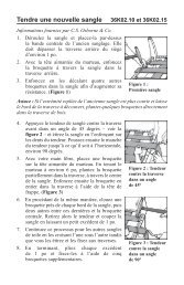
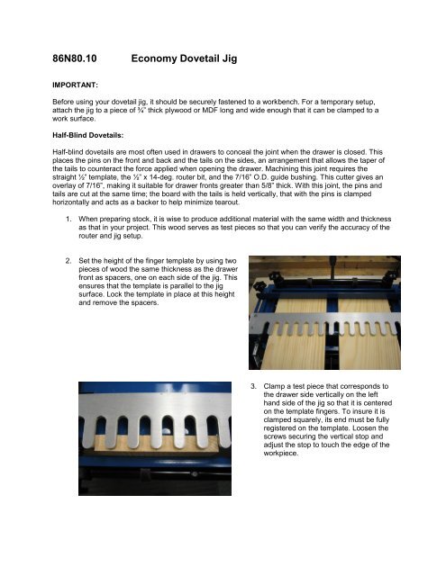
2. Set the height of the finger template by using two<br />
pieces of wood the same thickness as the drawer<br />
front as spacers, one on each side of the jig. This<br />
ensures that the template is parallel to the jig<br />
surface. Lock the template in place at this height<br />
and remove the spacers.<br />
3. Clamp a test piece that corresponds to<br />
the drawer side vertically on the left<br />
hand side of the jig so that it is centered<br />
on the template fingers. To insure it is<br />
clamped squarely, its end must be fully<br />
registered on the template. Loosen the<br />
screws securing the vertical stop and<br />
adjust the stop to touch the edge of the<br />
workpiece.
4. The drawer front must be offset 1/2” to<br />
the left of the side. On a test piece that<br />
represents the drawer front, mark a line<br />
on its end ½” in from the edge. Fasten<br />
this piece horizontally in the jig, insuring<br />
its end is registered against the face of<br />
the drawer side, and the ½” offset mark<br />
corresponds to the side’s edge. Set the<br />
horizontal stop against the edge of the<br />
drawer front.<br />
5. Repeat steps 3 & 4 on the right side of the jig. In this position, the two parts are offset to the right.<br />
6. Clamp test pieces against the stops on the left side of the jig.<br />
7. Adjust the template so that the ends of<br />
the fingers are about 1/8” back from the<br />
front face of the drawer side.<br />
8. Install the ½” 14-deg bit and 7/16” guide bushing in your router. Set the bit so that it projects<br />
about 11/16” below the router baseplate.<br />
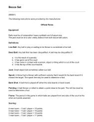
9. The fence limits the travel of the router by<br />
providing a positive stop for its base, and thus<br />
defines the length of the grooves cut between the<br />
template fingers. For a 5 ¾” diameter router base<br />
with a ½” diameter bit in ¾” lumber, set the fence<br />
3 15/16” from the tips of the template fingers. Be<br />
certain the fence is parallel to the template. For<br />
other router base sizes, use this formula:<br />
½” offset<br />
Side stop<br />
Drawer front/ back<br />
Drawer side<br />
3 15/16”
A x 2 + 1/32” + B = C<br />
A= Amount the template overlaps the vertical board<br />
B= Distance from the edge of the bushing to the edge of the router base<br />
C= Distance from fence to front of template<br />
10. Place the router on the template and make a cut from right to left, just touching the tip of each<br />
finger. This scoring cut helps prevent tearout. Without lifting the router, cut a test joint by<br />
traversing the template from left to right.<br />
11. Turn off the router and wait for the bit to stop rotating before lifting the router from the jig. If the<br />
router is removed while still running, the bit will damage the template.<br />
12. Remove both pieces from the fixture and test the joint for fit. If the joint is too loose, increase the<br />
depth of cut; if too tight, raise the bit. If the tails protrude from the sockets, adjust the fence<br />
towards the rear of the jig slightly; if the tails are recessed, move the fence toward the front.<br />
13. Continue milling test pieces until you are satisfied, and then make a test joint to verify the setup<br />
on the right side of the fixture. Once all is adjusted, proceed to cutting the joints for your drawer.<br />
14. <strong>Dovetail</strong>s for the left front corner and right rear corner of a drawer are cut on the left side of the<br />
jig; joints for the right front corner and left rear corner are machined using the stops on the right. It<br />
is a good idea to keep track of the parts by numbering the joints and labeling each component.
Through <strong>Dovetail</strong>s:<br />
So-named because the joint is visible on both parts, the through dovetail also has a decorative aspect<br />
provided by the contrast between end- and face grain. The joint derives some of its strength from the<br />
mechanical lock provided by the taper, and it is well to bear this in mind when orienting the components in<br />
the finished piece. If making a cabinet or drawer, place the tails on the side pieces for maximum strength.<br />
To produce this joint, the tails are cut first using the straight template and a ½” 8-deg router bit and 7/16”<br />
O.D. guide bushing. The pins are machined second, as it is this step that determines the fit of the joint.<br />
The 8-deg pin template is installed in the jig and a 5/16” straight cutter in the router. Both the pins and<br />
tails are machined with the work held vertically on the left side of the fixture.<br />
1. Layout the parts and label the front and back (or top and bottom in the case of a cabinet), along<br />
with the two sides. Determine which will have the pins or tails, and mark a “t” or a “p” on the<br />
inside faces. Number the joint at each corner.<br />
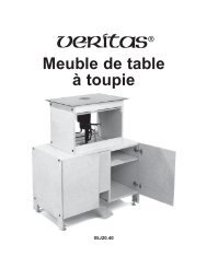
2. A spacer is required to set the finger template to<br />
the correct height and parallel to the jig surface.<br />
Use a piece of wood the same thickness as your<br />
dovetail stock about 11” wide and 7” deep, along<br />
with a thin (¼”) shim made of hardboard or<br />
plywood. Secure these pieces with their edges<br />
aligned with the front face of the jig. As you will<br />
be making cuts slightly deeper than the<br />
thickness of the stock, the shim is needed to<br />
prevent the router bit from running into the jig.<br />
The spacer helps prevent tearout by acting as a<br />
backer.<br />
Spacer<br />
¼” Shim<br />
3. Prepare a test piece the same width and thickness as the dovetail stock. Use a marking gauge<br />
set to the stock thickness plus about 1/32” to scribe a line across the ends.<br />
4. Secure this piece vertically on the left<br />
side of the jig so that it is centered on<br />
the template fingers. Ensure that its end<br />
is fully registered against the template.<br />
Set the left side stop against the edge of<br />
the test piece.<br />
Workpiece<br />
centered on<br />
fingers
5. Check the position of the template to verify<br />
that the point where the straight sides of the<br />
fingers meet their round ends lies just<br />
beyond the face of the stock.<br />
6. Install the ½” 8-deg cutter in the router,<br />
place the router on the finger template,<br />
and use the line made by the marking<br />
gauge to set the depth of cut.<br />
7. Place the router on the template, ensuring the cutter is not in contact with the stock. Turn on the<br />
router and machine the tails, beginning from the left side of the workpiece. Follow the notch<br />
between each finger in a clockwise rotation, keeping the bushing registered against the finger<br />
edge.<br />
8. If you’re satisfied with the setup, cut the tails for your project. Clamp the first piece in the jig with<br />
its inside surface facing out. Turn it end for end to mill the tails on the other end. Repeat for the<br />
second piece.<br />
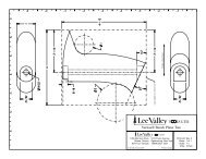
9. The setup for the pins determines the fit of the joint. Replace the dovetail bit with the 5/16”<br />
straight cutter and install the 8-deg through dovetail finger template. Set the position of the<br />
template so that the inside face of the vertical support and jig body is about 1 5/16”. This setting is<br />
suitable for different material thicknesses.<br />
1 5/16”<br />
8-deg through<br />
template
10. Prepare a test piece for the pins. Use the marking gauge to scribe a line across the ends.<br />
Position the test piece in the jig against the left side stop and secure the clamp. Set the depth of<br />
the router bit as in step 6.<br />
11. Begin with the first recess on the left side of the stock. Make a series of sideways cuts and finish<br />
by following the angled sides of the fingers. Repeat for each recess.<br />
12. Test the fit of the joint. If tight, move the template away from you slightly; if loose, shift the<br />
template towards you. Follow this process until a good fit is achieved.<br />
13. Cut the pins for your project. The inside surface of the stock must always face towards the jig.