
Create successful ePaper yourself
Turn your PDF publications into a flip-book with our unique Google optimized e-Paper software.
4000 Peak Watts / 3500 Running Watts<br />
Wireless Remote Electric Start<br />
<strong>PORTABLE</strong> <strong>GENERATOR</strong><br />
SAvE THESE INSTRuCTIONS<br />
Important Safety Instructions<br />
are included in this manual.<br />
OWNER’S MANUAL & OPERATING INSTRUCTIONS<br />
2 yEAR<br />
LIMITED WARRANTY<br />
MADE IN CHINA<br />
REV 46512-20110823<br />
MODEL NUMBER<br />
46512<br />
10006 Santa Fe Springs Road<br />
Santa Fe Springs CA 90670<br />
USA / 1 (877) 338-0999<br />
www.championpowerequipment.com
Have questions or need assistance?<br />
Do not return this product to the store!<br />
WE ARE HERE TO HELP!<br />
Visit our website:<br />
www.championpowerequipment.com<br />
for more info:<br />
• Product Info & Updates<br />
• Frequently Asked Questions<br />
– or –<br />
• Tech Bulletins<br />
• Product Registration<br />
Call our Customer Care Team Toll-Free at:<br />
1-877-338-0999<br />
24/7 Tech Support: (562) 204-1188
TABLE Of CONTENTS<br />
Introduction . . . . . . . . . . . . . . . . . . . . . . . . . . . . . 1<br />
Introduction . . . . . . . . . . . . . . . . . . . . . . . . . . . 1<br />
Portable Power Generator . . . . . . . . . . . . . . . . . . 1<br />
Accessories . . . . . . . . . . . . . . . . . . . . . . . . . . . 1<br />
This Booklet . . . . . . . . . . . . . . . . . . . . . . . . . . . 1<br />
Manual Conventions . . . . . . . . . . . . . . . . . . . . . . . . 2<br />
Safety Rules . . . . . . . . . . . . . . . . . . . . . . . . . . . . . 3<br />
Controls and Features . . . . . . . . . . . . . . . . . . . . . . 5<br />
Generator . . . . . . . . . . . . . . . . . . . . . . . . . . . . . 5<br />
Power Panel . . . . . . . . . . . . . . . . . . . . . . . . . . . 6<br />
Wireless Remote Control . . . . . . . . . . . . . . . . . . 7<br />
Remote Control Power Consumption . . . . . . . . 7<br />
Power Panel Load Management . . . . . . . . . . . 7<br />
Parts Included . . . . . . . . . . . . . . . . . . . . . . . . . 8<br />
Wheel Kit . . . . . . . . . . . . . . . . . . . . . . . . . . 8<br />
Spark Arrester Kit . . . . . . . . . . . . . . . . . . . . . 8<br />
Other . . . . . . . . . . . . . . . . . . . . . . . . . . . . . 8<br />
Assembly . . . . . . . . . . . . . . . . . . . . . . . . . . . . . . . 9<br />
Remove the Generator from the Shipping Carton . . 9<br />
Install the Wheel Kit . . . . . . . . . . . . . . . . . . . . . 9<br />
Install the Support Leg . . . . . . . . . . . . . . . . . . . 9<br />
Install the Handles . . . . . . . . . . . . . . . . . . . . . . 9<br />
Connect the Battery . . . . . . . . . . . . . . . . . . . . 10<br />
Install the Spark Arrester . . . . . . . . . . . . . . . . . 10<br />
Add Engine Oil . . . . . . . . . . . . . . . . . . . . . . . . 10<br />
Add Fuel . . . . . . . . . . . . . . . . . . . . . . . . . . . . 11<br />
Grounding . . . . . . . . . . . . . . . . . . . . . . . . . . . 11<br />
Operation . . . . . . . . . . . . . . . . . . . . . . . . . . . . . . 12<br />
Generator Location . . . . . . . . . . . . . . . . . . . . . 12<br />
Grounding . . . . . . . . . . . . . . . . . . . . . . . . . . . 12<br />
Surge Protection . . . . . . . . . . . . . . . . . . . . . . . 12<br />
Wireless Remote Start . . . . . . . . . . . . . . . . . . . 12<br />
Starting the Engine without Remote . . . . . . . . . . 12<br />
Connecting Electrical Loads . . . . . . . . . . . . . . . 13<br />
Stopping the Engine . . . . . . . . . . . . . . . . . . . . 13<br />
Do Not Overload Generator . . . . . . . . . . . . . . . . 14<br />
Capacity . . . . . . . . . . . . . . . . . . . . . . . . . . 14<br />
Power Management . . . . . . . . . . . . . . . . . . . 14<br />
Wattage Reference Chart . . . . . . . . . . . . . . . . . 14<br />
46512<br />
4000 Peak Watts / 3500 Running Watts<br />
Wireless Remote Electric Start<br />
<strong>PORTABLE</strong> <strong>GENERATOR</strong><br />
Maintenance and Storage . . . . . . . . . . . . . . . . . . . 15<br />
Engine Maintenance . . . . . . . . . . . . . . . . . . . . 15<br />
Oil . . . . . . . . . . . . . . . . . . . . . . . . . . . . . . 15<br />
Spark Plugs . . . . . . . . . . . . . . . . . . . . . . . . 15<br />
Air Filter . . . . . . . . . . . . . . . . . . . . . . . . . . 15<br />
Spark Arrester . . . . . . . . . . . . . . . . . . . . . . 16<br />
Cleaning . . . . . . . . . . . . . . . . . . . . . . . . . . 16<br />
Adjustments . . . . . . . . . . . . . . . . . . . . . . . . 16<br />
Maintenance Schedule . . . . . . . . . . . . . . . . 16<br />
Generator Maintenance . . . . . . . . . . . . . . . . . . 17<br />
Storage . . . . . . . . . . . . . . . . . . . . . . . . . . . . . 17<br />
Generator Storage . . . . . . . . . . . . . . . . . . . . 17<br />
Disconnect the Battery . . . . . . . . . . . . . . . . 17<br />
Charge the Battery . . . . . . . . . . . . . . . . . . . 17<br />
Specifications . . . . . . . . . . . . . . . . . . . . . . . . . . . 18<br />
Engine Specifications . . . . . . . . . . . . . . . . . . . 18<br />
Generator Specifications . . . . . . . . . . . . . . . . . 18<br />
Fuel . . . . . . . . . . . . . . . . . . . . . . . . . . . . . . . 18<br />
Oil . . . . . . . . . . . . . . . . . . . . . . . . . . . . . . . . 18<br />
Spark Plugs . . . . . . . . . . . . . . . . . . . . . . . . . . 18<br />
Valve Clearance . . . . . . . . . . . . . . . . . . . . . . . 18<br />
FCC Statement for Remote Control Device . . . . . 18<br />
Parts Diagram . . . . . . . . . . . . . . . . . . . . . . . . 19<br />
Parts List . . . . . . . . . . . . . . . . . . . . . . . . . . . . 20<br />
Engine Parts Diagram . . . . . . . . . . . . . . . . . . . 21<br />
Engine Parts List . . . . . . . . . . . . . . . . . . . . . . 22<br />
Wiring Diagram . . . . . . . . . . . . . . . . . . . . . . . . 23<br />
Troubleshooting . . . . . . . . . . . . . . . . . . . . . . . . . . 24<br />
Warranty . . . . . . . . . . . . . . . . . . . . . . . . . . . . . . 25<br />
Warranty Qualifications . . . . . . . . . . . . . . . . . . 25<br />
Repair/Replacement Warranty . . . . . . . . . . . . . . 25<br />
Do Not Return The Unit To<br />
The Place Of Purchase . . . . . . . . . . . . . . . . . . 25<br />
Warranty Exclusions . . . . . . . . . . . . . . . . . . . . 25<br />
Normal Wear . . . . . . . . . . . . . . . . . . . . . . . 25<br />
Installation, Use and Maintenance . . . . . . . . 25<br />
Other Exclusions . . . . . . . . . . . . . . . . . . . . . 25<br />
Limits of Implied Warranty<br />
and Consequential Damage . . . . . . . . . . . . . 25<br />
Contact Information . . . . . . . . . . . . . . . . . . . . . 25<br />
Address . . . . . . . . . . . . . . . . . . . . . . . . . . . 25<br />
Customer Service . . . . . . . . . . . . . . . . . . . . 25<br />
Technical Service . . . . . . . . . . . . . . . . . . . . 25<br />
Emission Control System Warranty . . . . . . . . . . 26
INTROduCTION<br />
Introduction<br />
Congratulations on your purchase of a Champion<br />
Power Equipment generator . CPE designs and builds<br />
generators to strict specifications . With proper use and<br />
maintenance, this generator will bring years of satisfying<br />
service .<br />
Portable Power Generator<br />
This unit is a gasoline engine driven, alternating current<br />
(AC) generator . It is designed to supply electrical power<br />
for lighting, appliances, tools and similar equipment .<br />
1 REV 46512-20110823<br />
Accessories<br />
ENGLISH 46512<br />
Champion Power Equipment manufactures and sells<br />
accessories designed to help you get the most from<br />
your purchase . To find out more about our covers, power<br />
cables and storm kits, please visit our web site at:<br />
www.championpowerequipment.com<br />
This Booklet<br />
Every effort has been made to ensure the accuracy and<br />
completeness of the information in this manual . We reserve<br />
the right to change, alter and/or improve the product and<br />
this document at any time without prior notice .<br />
Record the model and serial numbers as well as date and place of purchase for future reference . Have this<br />
information available when ordering parts and when making technical or warranty inquiries .<br />
Champion Power Equipment Support<br />
1 (877) 338-0999<br />
Model Number<br />
46512<br />
Serial Number<br />
Date of Purchase<br />
Purchase Location<br />
For Oil Type see ‘Add Engine Oil‘ section . For Fuel Type see ‘Add Fuel‘ section .
46512 ENGLISH<br />
MANuAL CONvENTIONS<br />
This manual uses the following symbols to help differentiate between different kinds of information . The safety symbol<br />
is used with a key word to alert you to potential hazards in operating and owning power equipment .<br />
Follow all safety messages to avoid or reduce the risk of serious injury or death .<br />
dANGER<br />
DANGER indicates an imminently hazardous<br />
situation which, if not avoided, will result in death<br />
or serious injury .<br />
WARNING<br />
WARNING indicates a potentially hazardous<br />
situation which, if not avoided, could result in<br />
death or serious injury .<br />
CAuTION<br />
CAUTION indicates a potentially hazardous<br />
situation which, if not avoided, may result in minor<br />
or moderate injury .<br />
CAuTION<br />
CAUTION used without the safety alert symbol<br />
indicates a potentially hazardous situation which, if<br />
not avoided, may result in property damage .<br />
NOTE<br />
If you have questions regarding your generator, we can<br />
help . Please call our help line at 1 (877) 338-0999<br />
REV 46512-20110823 2
SAfETy RuLES<br />
WARNING<br />
Read this manual thoroughly before operating your<br />
generator . Failure to follow instructions could result<br />
in serious injury or death .<br />
WARNING<br />
The engine exhaust from this product contains<br />
chemicals known to the state of California to cause<br />
cancer, birth defects, or other reproductive harm .<br />
dANGER<br />
Generator exhaust contains carbon monoxide, a<br />
colorless, odorless, poison gas . Breathing carbon<br />
monoxide will cause nausea, dizziness, fainting or<br />
death . If you start to feel dizzy or weak, get to fresh<br />
air immediately .<br />
Operate generator outdoors only in a well ventilated<br />
area .<br />
DO NOT operate the generator inside any building,<br />
including garages, basements, crawlspaces and<br />
sheds, enclosure or compartment, including the<br />
generator compartment of a recreational vehicle .<br />
DO NOT allow exhaust fumes to enter a confined<br />
area through windows, doors, vents or other<br />
openings .<br />
DANGER CARBON MONOXIDE: using a generator<br />
indoors CAN KILL YOU IN MINUTES .<br />
dANGER<br />
Rotating parts can entangle hands, feet, hair,<br />
clothing and/or accessories .<br />
Traumatic amputation or severe laceration can result .<br />
Keep hands and feet away from rotating parts .<br />
Tie up long hair and remove jewelry .<br />
Operate equipment with guards in place .<br />
DO NOT wear loose-fitting clothing, dangling<br />
drawstrings or items that could become caught .<br />
3 REV 46512-20110823<br />
dANGER<br />
Generator produces powerful voltage .<br />
ENGLISH 46512<br />
DO NOT touch bare wires or receptacles .<br />
DO NOT use electrical cords that are worn, damaged<br />
or frayed .<br />
DO NOT operate generator in wet weather .<br />
DO NOT allow children or unqualified persons to<br />
operate or service the generator<br />
Use a ground fault circuit interrupter (GFCI) in damp<br />
areas and areas containing conductive material such<br />
as metal decking .<br />
Use approved transfer equipment to isolate generator<br />
from your electric utility and Notify your utility<br />
company before connecting your generator to your<br />
power system .<br />
WARNING<br />
Sparks can result in fire or electrical shock .<br />
When servicing the generator:<br />
Disconnect the spark plug wire and place it where it<br />
cannot contact the plug .<br />
DO NOT check for spark with the plug removed .<br />
Use only approved spark plug testers .<br />
WARNING<br />
Running engines produce heat . Severe burns can<br />
occur on contact .<br />
Combustible material can catch fire on contact .<br />
DO NOT touch hot surfaces .<br />
Avoid contact with hot exhaust gases .<br />
Allow equipment to cool before touching .<br />
Maintain at least three feet of clearance on all sides<br />
to ensure adequate cooling .<br />
Maintain at least five feet of clearance from<br />
combustible materials .
46512 ENGLISH<br />
dANGER<br />
Fuel and fuel vapors are highly flammable and<br />
extremely explosive .<br />
Fire or explosion can cause severe burns or death .<br />
Unintentional startup can result in entanglement,<br />
traumatic amputation or laceration .<br />
When adding or removing fuel:<br />
Turn the generator off and let it cool for at least two<br />
minutes before removing the fuel cap . Loosen the<br />
cap slowly to relieve pressure in the tank .<br />
Only fill or drain fuel outdoors in a well-ventilated area .<br />
DO NOT overfill the fuel tank .<br />
Always keep fuel away from sparks, open flames,<br />
pilot lights, heat and other sources of ignition .<br />
DO NOT light or smoke cigarettes .<br />
When starting the generator:<br />
DO NOT attempt to start a damaged generator .<br />
Make certain that the gas cap, air filter, spark plug,<br />
fuel lines and exhaust system are properly in place .<br />
Allow spilled fuel to evaporate fully before<br />
attempting to start the engine .<br />
Make certain that the generator is resting firmly on<br />
level ground .<br />
When operating the generator:<br />
DO NOT move or tip the generator during operation .<br />
DO NOT tip the generator or allow fuel or oil to spill .<br />
When transporting or servicing the generator:<br />
Make certain that the fuel shutoff valve is in the off<br />
position and the fuel tank is empty .<br />
Disconnect the spark plug wire .<br />
When storing the generator:<br />
Store away from sparks, open flames, pilot lights,<br />
heat and other sources of ignition .<br />
WARNING<br />
Operation of this equipment may create sparks that<br />
can start fires around dry vegetation .<br />
A spark arrestor may be required . The operator<br />
should contact local fire agencies for laws or<br />
regulations relating to fire prevention requirements .<br />
WARNING<br />
SAfETy RuLES<br />
Rapid retraction of the starter cord will pull hand and<br />
arm towards the engine faster than you can let go .<br />
Unintentional startup can result in entanglement,<br />
traumatic amputation or laceration .<br />
Broken bones, fractures, bruises or sprains could result .<br />
When starting engine, pull the starter cord slowly<br />
until resistance is felt and then pull rapidly to avoid<br />
kickback .<br />
DO NOT start or stop the engine with electrical<br />
devices plugged in .<br />
CAuTION<br />
Exceeding the generator’s running capacity can<br />
damage the generator and/or electrical devices<br />
connected to it .<br />
DO NOT overload the generator .<br />
Start the generator and allow the engine to stabilize<br />
before connecting electrical loads .<br />
Connect electrical equipment in the off position,<br />
and then turn them on for operation .<br />
Turn electrical equipment off and disconnect before<br />
stopping the generator .<br />
DO NOT tamper with the governed speed .<br />
DO NOT modify the generator in any way .<br />
CAuTION<br />
Improper treatment or use of the generator can<br />
damage it, shorten its life and void your warranty .<br />
Use the generator only for intended uses .<br />
Operate only on level surfaces .<br />
DO NOT expose generator to excessive moisture,<br />
dust, or dirt .<br />
DO NOT allow any material to block the cooling slots .<br />
If connected devices overheat, turn them off and<br />
disconnect them from the generator .<br />
DO NOT use the generator if:<br />
– Electrical output is lost<br />
– Equipment sparks, smokes or emits flames<br />
– Equipment vibrates excessively<br />
REV 46512-20110823 4
CONTROLS ANd fEATuRES<br />
5 REV 46512-20110823<br />
ENGLISH 46512<br />
Read this owner’s manual before operating your generator . Familiarize yourself with the location and function of the<br />
controls and features . Save this manual for future reference .<br />
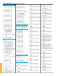
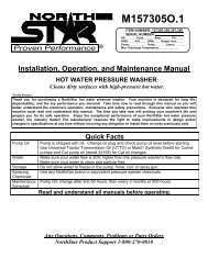
Generator<br />
2<br />
4<br />
3<br />
(1) Fuel Tank – 4 gallon (15 L) capacity fuel tank .<br />
(2) Auto-Choke – Used to start the engine . No manual<br />
adjustment required .<br />
(3) Fuel Valve – Turn this valve to the “On” position to<br />
supply fuel to the engine .<br />
(4) Air Cleaner – Protects the engine by filtering dust<br />
and debris from the intake air .<br />
5<br />
1<br />
6<br />
(5) Recoil Starter – Used to start the engine .<br />
(6) Oil Filler Cap – Check and fill engine oil level .<br />
(7) Battery – Used to start the engine . Provides 12V<br />
DC to the electric starter and receiver control<br />
module .<br />
(8) Power Panel – See “Power Panel” section .<br />
7<br />
8
46512 ENGLISH<br />
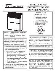
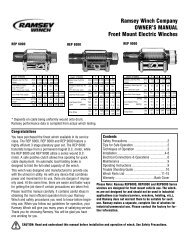
Power Panel<br />
(1) Intelligauge – Three mode digital meter for running<br />
hours, voltage and hertz .<br />
(2) Ignition Switch<br />
(3) Circuit Breaker(s) – Protects the generator against<br />
electrical overload .<br />
(4) Battery Switch – Enables/disables starting<br />
electrically – via remotely or by Ignition Switch .<br />
(5) Ground Terminal – Consult an electrician for local<br />
grounding regulations .<br />
4<br />
1<br />
2<br />
CONTROLS ANd fEATuRES<br />
5 6 7 8<br />
3<br />
(6) 120V / 30A Twist-Lock – This receptacle powers<br />
120 Volt AC, 60 Hz, single phase loads requiring<br />
up to 29 .2 Amps or 3500 Watts of power .<br />
(7) 120V / 30A Recreational Vehicle (RV) Receptacle –<br />
This receptacle powers 120 Volt AC, 60 Hz, single<br />
phase loads requiring up to 29 .2 Amps or 3500<br />
Watts of power .<br />
(8) 120V / 20A Duplex – Protected by a 20 Amp<br />
push-to-reset circuit breaker . Use each recepticle<br />
to operate 120 Volt AC, single phase, 60 Hz loads<br />
requiring up to 20 Amp 0r 2400 Watts of power .<br />
REV 46512-20110823 6
CONTROLS ANd fEATuRES<br />
Wireless Remote Control<br />
This generator is equipped with a wireless remote<br />
control system for starting and stopping . The system<br />
consists of (4) main components:<br />
1 . Receiver Control Module (RCM)<br />
2 . Wireless Remote<br />
3 . Battery Switch<br />
4 . Ignition Switch<br />
The Remote Control functions are enabled when:<br />
1 . The Ignition Switch is in the “ON” position, AND<br />
2 . The Battery Switch is in the “ON” position .<br />
The Remote Control functions are disabled if either of<br />
the above conditions is not met .<br />
To start the generator by Remote Control, press the<br />
“START” button on the Remote one time . The engine<br />
will attempt to start (6) times . The RCM controls<br />
the Auto Choke during each attempt to start . If the<br />
generator does not start, call Champion Customer Care<br />
team for assistance at 1 (877) 338-0999 .<br />
To stop the generator by Remote Control, press the<br />
“STOP” button on the Remote one time .<br />
Remote Control Power Consumption<br />
While the Ignition Switch is in the “ON: position, the<br />
RCM is active and waiting for a remote signal . This<br />
function requires electrical current from the battery .<br />
If the Ignition Switch is left in the “ON” position for<br />
extended periods (several weeks), the battery can be<br />
completely drained .<br />
Moving the Ignition Switch to the “OFF” position<br />
disables the Remote functions, but the RCM still<br />
consumes approximately 2 mA from the battery .<br />
To prevent battery drain, press the Battery Switch to the<br />
“OFF” position . This disconnects power to the RCM so<br />
there is no current draw on the battery .<br />
Power Panel Load Management<br />
When the generator initially starts by the Remote, no<br />
voltage is supplied to the Power Panel for approximately<br />
15 seconds . This allows the engine to reach full speed<br />
before electrical loads are applied to the generator .<br />
When the generator is stopped by the Remote, the<br />
voltage to the Power Panel is immediately turned off .<br />
Then the engine stops approximately 5 seconds after<br />
the “STOP” button on the Remote is pressed . Turning<br />
the Power Panel voltage off before the engine shutdown<br />
protects connected appliances from being damaged by<br />
non-60 Hz voltage while the generator coasts to a stop .<br />
The on/off voltage delay at startup and shut down only<br />
happen when the Remote Control is used. There is no<br />
7 REV 46512-20110823<br />
Power Panel Load Management Cont’d.<br />
ENGLISH 46512<br />
voltage delay when the pushbutton electric start or recoil<br />
start method is used.<br />
When the pushbutton electric start or recoil start<br />
method is used, the operator must be sure all electrical<br />
loads (appliances) are turned OFF during startup and<br />
shutdown . Damage to the generator or the attached<br />
appliances can be caused by starting or stopping the<br />
generator while appliances are plugged in and turned ON .
46512 ENGLISH<br />
Parts Included<br />
Your 46512 Gasoline Powered Generator ships with the<br />
following parts:<br />
Wheel Kit<br />
– 8” Wheel . . . . . . . . . . . . . . . . . . . . . . . . . . . . . 2<br />
– Vibration Mounts . . . . . . . . . . . . . . . . . . . . . . . . 2<br />
– Support Leg . . . . . . . . . . . . . . . . . . . . . . . . . . . 1<br />
– Bushing . . . . . . . . . . . . . . . . . . . . . . . . . . . . . . 2<br />
– Handle . . . . . . . . . . . . . . . . . . . . . . . . . . . . . . 1<br />
– Flange Bolt (M10x105 for Wheel) . . . . . . . . . . . . 2<br />
– Flange Bolt (M8x45 for Handle) . . . . . . . . . . . . . 2<br />
– Flange Bolt (M8x25 for Vibration Mounts) . . . . . . 2<br />
– Flange Bolt (M8x16 for Support Leg) . . . . . . . . . . 2<br />
– Nut (M10) . . . . . . . . . . . . . . . . . . . . . . . . . . . . 2<br />
– Flat Washer 10 . . . . . . . . . . . . . . . . . . . . . . . . . 2<br />
– Nut (M8) . . . . . . . . . . . . . . . . . . . . . . . . . . . . 6<br />
Spark Arrester Kit<br />
– Spark Arrestor . . . . . . . . . . . . . . . . . . . . . . . . . 1<br />
– Cover Plate . . . . . . . . . . . . . . . . . . . . . . . . . . . . 1<br />
– Screw with Lock Washer . . . . . . . . . . . . . . . . . . . . 2<br />
Other<br />
– Oil Funnel . . . . . . . . . . . . . . . . . . . . . . . . . . . . 1<br />
– Oil . . . . . . . . . . . . . . . . . . . . . . . . . . . . . . 0 .6 L<br />
– Spark Plug Socket . . . . . . . . . . . . . . . . . . . . . . . 1<br />
– Remote . . . . . . . . . . . . . . . . . . . . . . . . . . . . . . 1<br />
– Cap Screw (M6x10 for Battery Terminals) . . . . . . . 2<br />
– Nut (M6) . . . . . . . . . . . . . . . . . . . . . . . . . . . . . 2<br />
CONTROLS ANd fEATuRES<br />
(Battery Bolts)<br />
REV 46512-20110823 8
ASSEMBLy<br />
Your generator requires some assembly . This unit ships<br />
from our factory without oil . It must be properly serviced<br />
with fuel and oil before operation .<br />
If you have any questions regarding the assembly of your<br />
generator, call our help line at 1 (877) 338-0999 . Please<br />
have your serial number and model number available .<br />
Remove the Generator from the Shipping Carton<br />
1 . Set the shipping carton on a solid, flat surface .<br />
2 . Remove everything from the carton except the<br />
generator .<br />
3 . Carefully cut each corner of the box from top to<br />
bottom . Fold each side flat on the ground to provide a<br />
surface area to install the wheel kit and support leg .<br />
Install the Wheel Kit<br />
CAuTION<br />
The wheel kit is not intended for over-the-road use .<br />
You will need the following tools to install the wheels:<br />
• 17 mm wrench OR adjustable wrench (not included)<br />
• Socket wrench with a 16 mm socket (not included)<br />
• Pliers (not included)<br />
1 . Before adding fuel and oil, tip the generator on it’s side .<br />
2 . Slide the M10x105 wheel bolt through the washer,<br />
sleeve and wheel .<br />
3 . Slide the bolt through the mount point on the frame .<br />
4 . Fasten securely with the M10 nut .<br />
5 . Repeat steps 2-4 to attach the second wheel .<br />
9 REV 46512-20110823<br />
Install the Support Leg<br />
Install the Handles<br />
ENGLISH 46512<br />
1 . Attach the support leg to the generator frame with<br />
cap screws (M8x16) and lock nuts (M8) .<br />
2 . Tip the generator slowly so that it rests on the<br />
wheels and support leg .<br />
1 . Place the handle over the mounting channel on the<br />
frame .<br />
2 . Secure the handle to the frame using the two handle<br />
bolts (M8x45) .<br />
3 . Place a lock nut (M8) on the end of each bolt and<br />
fasten securely . DO NOT over tighten the lock nuts .
46512 ENGLISH<br />
Connect the Battery<br />
1 . Remove the protective cover from the red (+) lead on<br />
the battery .<br />
2 . Attach the red (+) lead to the red (+) terminal on the<br />
battery with the cap screw (M6x10) and secure with<br />
the lock washer (M6) .<br />
3 . Repeat steps 1-2 for the black (–) battery lead .<br />
Install the Spark Arrester<br />
Insert the spark arrester screen into the muffler outlet .<br />
Secure the spark arrester by placing the cover plate over<br />
the end of the screen, with the lettering facing outward .<br />
Secure the cover plate with the two screws and lock<br />
washers provided with the spark arrester kit .<br />
NOTE<br />
Federal and local laws and administrative<br />
requirements indicate when and where spark<br />
arresters are required . When ordered, spark<br />
arresters are required for operation of this generator<br />
in National Forest lands . In California, this<br />
generator must not be used on any forest- covered<br />
land, brush-covered land, or grass- covered land<br />
unless the engine is equipped with a spark arrester .<br />
CAuTION<br />
Failure to install the spark arrester may result in an<br />
increased risk of fire .<br />
Add Engine Oil<br />
CAuTION<br />
NOTE<br />
The recommended oil type is 10W-30 4-cycle<br />
automotive oil . Please see “Specifications” section<br />
for more information on oil types .<br />
1 . Place the generator on a flat, level surface .<br />
2 . Remove oil fill cap/dipstick to add oil .<br />
3 . Add 0 .63 qt (0 .6 L) of oil (included) and replace oil<br />
fill cap/dipstick . See “Specifications” pages for oil<br />
recommendations based on operating conditions .<br />
4 . Check engine oil level daily and add as needed .<br />
CAuTION<br />
ASSEMBLy<br />
DO NOT attempt to crank or start the engine before<br />
it has been properly filled with the recommended<br />
type and amount of oil . Damage to the generator as<br />
a result of failure to follow these instructions will<br />
void your warranty .<br />
The engine is equipped with a low-oil-shutoff and<br />
will stop when the oil level in the crankcase falls<br />
below the threshold level .<br />
REV 46512-20110823 10
ASSEMBLy<br />
Add Engine Oil Cont’d.<br />
Check oil often during the break-in period . Refer to the<br />
Maintenance section for recommended service intervals .<br />
Add fuel<br />
NOTE<br />
NOTE<br />
The generator rotor has a sealed, pre-lubricated ball<br />
bearing that requires no additional lubrication for<br />
the life of the bearing .<br />
1 . Use clean, fresh, regular unleaded fuel with a<br />
minimum octane rating of 85 and an ethanol content<br />
of less than 10% by volume .<br />
2 . DO NOT mix oil with fuel .<br />
3 . Clean the area around the fuel cap .<br />
4 . Remove the fuel cap .<br />
5 . Slowly add fuel to the tank . DO NOT overfill . Allow<br />
approximately ½ inch of space for fuel expansion .<br />
6 . Screw on the fuel cap and wipe away any spilled fuel .<br />
CAuTION<br />
Use regular unleaded gasoline with a minimum<br />
octane rating of 85 .<br />
Do not mix oil and gasoline .<br />
Fill tank to approximately ½ inch below the top of<br />
the tank to allow for fuel expansion .<br />
DO NOT fill fuel tank indoors .<br />
DO NOT fill fuel tank when the engine is running or hot .<br />
DO NOT overfill the fuel tank .<br />
DO NOT light cigarettes or smoke when filling the<br />
fuel tank .<br />
11 REV 46512-20110823<br />
Grounding<br />
ENGLISH 46512<br />
Your generator must be properly connected to an<br />
appropriate ground to help prevent electric shock .<br />
WARNING<br />
Failure to properly ground the generator can result<br />
in electric shock .<br />
A ground terminal connected to the frame of the generator<br />
has been provided on the power panel . For remote<br />
grounding, connect of a length of heavy gauge (12 AWG<br />
minimum) copper wire between the generator ground<br />
terminal and a copper rod driven into the ground . We<br />
strongly recommend that you consult with a qualified<br />
electrician to ensure compliance with local electrical codes .
46512 ENGLISH<br />
Generator Location<br />
Please consult your local authority . In some areas,<br />
generators must be registered with the local utility .<br />
Generators used at construction sites may be subject to<br />
additional rules and regulations .<br />
This generator must have at least five feet of clearance<br />
from combustible material . Leave at least three feet<br />
of clearance on all sides of the generator to allow for<br />
adequate cooling, maintenance and servicing .<br />
Place the generator in a well-ventilated area . DO NOT<br />
place the generator near vents or intakes where exhaust<br />
fumes could be drawn into occupied or confined<br />
spaces . Carefully consider wind and air currents when<br />
positioning generator .<br />
Grounding<br />
The generator system ground connects the frame to the<br />
ground terminals on the power panel .<br />
Surge Protection<br />
CAuTION<br />
Voltage fluctuation may impair the proper<br />
functioning of sensitive electronic equipment .<br />
Electronic devices, including computers and many<br />
programmable appliances use components that are<br />
designed to operate within a narrow voltage range and<br />
may be affected by momentary voltage fluctuations .<br />
While there is no way to prevent voltage fluctuations, you<br />
can take steps to protect sensitive electronic equipment .<br />
1. Install UL1449, CSA-listed, plug-in surge suppressors<br />
on the outlets feeding your sensitive equipment.<br />
Surge suppressors come in single- or multi-outlet<br />
styles . They’re designed to protect against virtually<br />
all short-duration voltage fluctuations .<br />
Wireless Remote Start<br />
Starting the Engine without Remote<br />
OPERATION<br />
Wireless remote starting is only possible within 80 feet of<br />
the generator .<br />
Do not attempt to adjust the carburetor choke . The remote<br />
system will automatically close and open the choke .<br />
1 . Make certain the generator is on a flat, level surface .<br />
2 . Press the Ignition Switch to “ON” .<br />
3 . Press the Battery Switch to “ON” .<br />
4 . Turn the Fuel Valve to the “ON” position .<br />
5 . To start the engine, press and release the “START”<br />
button on the handheld Remote Control device . DO<br />
NOT hold the button down, only press the button<br />
once . The engine will attempt to start 6 times .<br />
6 . A safety feature is provided which delays the<br />
electrical power availability during starting mode .<br />
The delay lasts for approximately 15 seconds . The<br />
delay is provided to prevent damage to the generator<br />
if electrical loads are inadvertently turned on during<br />
engine startup .<br />
7 . If the generator fails to start, check the battery<br />
condition and cable connections .<br />
1 . Make certain the generator is on a flat, level surface .<br />
2 . Turn off all electrical loads connected to the generator .<br />
Never start or stop the generator with electrical<br />
devices plugged in and turned on .<br />
3 . Turn the Fuel Valve to the “ON” position .<br />
4 . Press the Battery Switch to “ON” .<br />
5 . ELECTRIC START: Press the switch to the “START”<br />
position .<br />
6 . RECOIL START: Pull the starter cord slowly until<br />
resistance is felt and then pull rapidly .<br />
NOTE<br />
If the engine starts but does not run make certain<br />
that the generator is on a flat, level surface . The<br />
engine is equipped with a low oil sensor that will<br />
prevent the engine from running when the oil level<br />
falls below a critical threshold .<br />
REV 46512-20110823 12
OPERATION<br />
Connecting Electrical Loads<br />
1 . Let the engine stabilize and warm up for a few<br />
minutes after starting<br />
2 . Plug in and turn on the desired 120 Volt AC single<br />
phase, 60 Hz electrical loads .<br />
– DO NOT connect 3-phase loads to the generator .<br />
– DO NOT connect 50 Hz loads to the generator .<br />
– DO NOT overload the generator .<br />
13 REV 46512-20110823<br />
Stopping the Engine<br />
NOTE NOTE<br />
Connecting a generator to your electric utility<br />
company’s power lines or to another power source<br />
may be against the law . In addition this action,<br />
if done incorrectly, could damage your generator<br />
and appliances and could cause serious injury or<br />
even death to you or a utility worker who may be<br />
working on nearby power lines . If you plan to run a<br />
portable electric generator during an outage, please<br />
notify your electric utility company immediately<br />
and remember to plug your appliances directly<br />
into the generator . Do not plug the generator into<br />
any electric outlet in your home . Doing so could<br />
create a connection to the utility company power<br />
lines . You are responsible for ensuring that your<br />
generator’s electricity does not feed back into the<br />
electric utility power lines .<br />
If the generator will be connected to a building<br />
electrical system, consult your local utility company<br />
or a qualified electrician . Connections must isolate<br />
generator power from utility power and must comply<br />
with all applicable laws and codes .<br />
ENGLISH 46512<br />
1 . Turn off all electrical loads connected to the<br />
generator . Never start or stop the generator with<br />
electrical devices plugged in and turned on .<br />
2 . Press and release the STOP button on the Remote<br />
Control device OR turn the Ignition Switch to the<br />
“Off” position .<br />
3 . Turn the Fuel Valve to the “OFF” position .<br />
When the stop button on the remote is pressed,<br />
power to the receptacles is turned off and the<br />
engine will stop after 5 seconds .<br />
Important: If the generator will be moved or stored turn<br />
the Fuel Valve to the “OFF” position, press the Ignition<br />
Switch and the Battery Switch on the power panel to the<br />
“OFF” position .
46512 ENGLISH<br />
do Not Overload Generator<br />
Capacity<br />
Follow these simple steps to calculate the running and<br />
starting watts necessary for your purposes .<br />
1 . Select the electrical devices you plan on running at<br />
the same time .<br />
2 . Total the running watts of these items . This is<br />
the amount of power you need to keep your items<br />
running .<br />
3 . Identify the highest starting wattage of all devices<br />
identified in step 1 . Add this number to the number<br />
calculated in step 2 . Surge wattage is the extra<br />
burst of power needed to start some electric driven<br />
equipment . Following the steps listed under “Power<br />
Management” will guarantee that only one device will<br />
be starting at a time .<br />
Power Management<br />
Use the following formula to convert voltage and<br />
amperage to watts:<br />
Volts x Amps = Watts<br />
To prolong the life of your generator and attached<br />
devices, follow these steps to add electrical load:<br />
1 . Start the generator with no electrical load attached<br />
2 . Allow the engine to run for several minutes to stabilize .<br />
3 . Plug in and turn on the first item . It is best to attach<br />
the item with the largest load first .<br />
4 . Allow the engine to stabilize .<br />
5 . Plug in and turn on the next item .<br />
6 . Allow the engine to stabilize .<br />
7 . Repeat steps 5-6 for each additional item .<br />
NOTE<br />
Never exceed the specified capacity when adding<br />
loads to the generator .<br />
Wattage Reference Chart<br />
OPERATION<br />
Use the chart to determine approximate wattage<br />
requirements for your equipment .<br />
CAuTION<br />
Exceeding specified load capacity can result in<br />
damage to the generator .<br />
To determine total wattage necessary to power<br />
a device, ADD Running Watts to Starting Watts.<br />
(A+B) . Starting watts can exceed three times the<br />
running watts . The values in the following table are<br />
approximate . Refer to your tool or appliance for actual<br />
wattage consumption .<br />
Item<br />
Running<br />
Watts (A)<br />
Light Bulb 100W<br />
Essentials<br />
100<br />
Refrigerator/Freezer 1200 2400<br />
Freezer 500 500<br />
Sump Pump 600 1800<br />
Well Pump 1 HP 2000 4000<br />
Water Heater 4000<br />
Security System 180<br />
AM/FM Radio 300<br />
Garage Door Opener 1/2 HP 500 600<br />
Battery Charger 12V DC 110<br />
Heating/Cooling<br />
Air Conditioner 12000 BTU 1700 2500<br />
Fan 300 600<br />
Furnace Fan 1/3 HP 1200 2000<br />
Microwave 1000W<br />
Home Appliances<br />
1000<br />
Electric Range - One Element 1500<br />
Electric Skillet 1250<br />
Coffee Maker 1500<br />
Clothes Washer 1200<br />
CD/DVD Player / VCR<br />
Entertainment<br />
100<br />
Stereo Receiver 450<br />
Television 27” 500<br />
PC with 15” Monitor 800<br />
Job Site<br />
Belt Sander 3” 1000 1500<br />
Bench Grinder 6” 700 1500<br />
Circular Saw 1500 1500<br />
Compressor 1 1/2 HP 2500 2500<br />
Edge Trimmer 500 500<br />
Hand Drill 1/2” 1000 1000<br />
Lawn Mower 1200 1800<br />
Paint Sprayer 600 1200<br />
Table Saw 2000 2000<br />
Starting<br />
Watts (B)<br />
REV 46512-20110823 14
MAINTENANCE ANd STORAGE<br />
The owner/operator is responsible for all periodic<br />
maintenance .<br />
WARNING<br />
Never operate a damaged or defective generator .<br />
WARNING<br />
Tampering with the factory set governor will void<br />
your warranty .<br />
WARNING<br />
Improper maintenance will void your warranty .<br />
NOTE<br />
Maintenance, replacement, or repair of emission<br />
control devices and systems may be performed<br />
by any non-road engine repair establishment or<br />
individual .<br />
Complete all scheduled maintenance in a timely manner .<br />
Correct any issue before operating the generator .<br />
NOTE<br />
For service or parts assistance, contact our help<br />
line at 1 (877) 338-0999<br />
Engine Maintenance<br />
To prevent accidental starting, remove and ground spark<br />
plug wire before performing any service .<br />
Oil<br />
Change oil when the engine is warm . Refer to the oil<br />
specifi cation to select the proper grade of oil for your<br />
operating environment .<br />
1 . Remove the oil drain plug with a 12 mm socket and<br />
extension .<br />
2 . Allow the oil to drain completely .<br />
3 . Replace the drain plug .<br />
4 . Remove oil fi ll cap/dipstick to add oil .<br />
5 . Add 0 .63 qt (0 .6 L) of oil and replace oil fi ll<br />
cap/dipstick .<br />
6 . Dispose of used oil at an approved waste<br />
management facility .<br />
15 REV 46512-20110823<br />
Oil Cont’d.<br />
NOTE<br />
ENGLISH 46512<br />
Once oil has been added, a visual check should show<br />
oil about 1-2 threads from running out of the fi ll hole .<br />
If using the dipstick to check oil level, DO NOT screw<br />
in the dipstick while checking .<br />
Spark Plugs<br />
1 . Remove the spark plug cable from the spark plug .<br />
2 . Use the spark plug tool that shipped with your<br />
generator to remove the plug .<br />
3 . Inspect the electrode on the plug . It must be clean and<br />
not worn to produce the spark required for ignition .<br />
4 . Make certain the spark plug gap is 0 .7 - 0 .8mm or<br />
(0 .028 - 0 .031 in .) .<br />
0.7 - 0.8 mm<br />
0.028 - 0.031 in.<br />
5 . Refer to the spark plug recommendation chart when<br />
replacing the plug .<br />
6 . Carefully thread the plug into the engine .<br />
7 . Use the spark plug tool to fi rmly install the plug .<br />
8 . Attach the spark plug wire to the plug .<br />
Air filter<br />
1 . Remove the snap-on cover holding the air fi lter to<br />
the assembly .<br />
2 . Remove the foam element .<br />
3 . Wash in liquid detergent and water . Squeeze<br />
thoroughly dry in a clean cloth .<br />
4 . Saturate in clean engine oil .<br />
5 . Squeeze in a clean, absorbent cloth to remove all<br />
excess oil .<br />
6 . Place the fi lter in the assembly .<br />
7 . Reattach the air fi lter cover and snap in place .
46512 ENGLISH<br />
Spark Arrester<br />
1 . Allow the engine to cool completely before servicing<br />
the spark arrester .<br />
2 . Remove the two screws holding the cover plate which<br />
retains the end of the spark arrester to the muffler .<br />
3 . Remove the spark arrester screen .<br />
4 . Carefully remove the carbon deposits from the spark<br />
arrester screen with a wire brush .<br />
5 . Replace the spark arrester if it is damaged .<br />
6 . Position the spark arrester in the muffler and attach<br />
with the two screws .<br />
Cleaning<br />
CAuTION<br />
Failure to clean the spark arrester will result in<br />
degraded engine performance .<br />
CAuTION<br />
DO NOT spray engine with water .<br />
Water can contaminate the fuel system .<br />
Use a damp cloth to clean exterior surfaces of the engine .<br />
Use a soft bristle brush to remove dirt and oil .<br />
Use an air compressor (25 PSI) to clear dirt and debris<br />
from the engine .<br />
Adjustments<br />
The air-fuel mixture is not adjustable . Tampering with<br />
the governor can damage your generator and your<br />
electrical devices and will void your warranty . CPE<br />
recommends that you contact our service line at<br />
1 (877) 338-0999 for all other service and/or<br />
adjustment needs .<br />
MAINTENANCE ANd STORAGE<br />
Maintenance Schedule<br />
Follow the service intervals indicated in the following<br />
maintenance schedule .<br />
Service your generator more frequently when operating<br />
in adverse conditions .<br />
Contact our help line at 1 (877) 338-0999 to locate the<br />
nearest Champion Power Equipment certified service<br />
dealer for your generator or engine maintenance needs .<br />
Every 8 hours or daily<br />
Check oil level<br />
Clean around air intake and muffler<br />
First 5 Hours<br />
Change oil<br />
Every 50 hours or every season<br />
Clean air filter<br />
Change oil if operating under heavy load or in hot<br />
environments<br />
Every 100 hours or every season<br />
Change oil<br />
Clean/Adjust spark plug<br />
Check/Adjust valve clearance *<br />
Clean spark arrester<br />
Clean fuel tank and filter *<br />
Every 3 years<br />
Replace fuel line<br />
*To be performed by knowledgeable, experienced owners or<br />
Champion Power Equipment certified dealers .<br />
REV 46512-20110823 16
MAINTENANCE ANd STORAGE<br />
Generator Maintenance<br />
Make certain that the generator is kept clean and stored<br />
properly . Only operate the unit on a flat, level surface in<br />
a clean, dry operating environment . DO NOT expose the<br />
unit to extreme conditions, excessive dust, dirt, moisture<br />
or corrosive vapors .<br />
DO NOT use a garden hose to clean the generator .<br />
Water can enter the generator through the cooling<br />
slots and damage the generator windings .<br />
Use a damp cloth to clean exterior surfaces of the generator .<br />
Use a soft bristle brush to remove dirt and oil .<br />
Use an air compressor (25 PSI) to clear dirt and debris<br />
from the generator .<br />
Inspect all air vents and cooling slots to ensure that they<br />
are clean and unobstructed .<br />
Storage<br />
CAuTION<br />
The generator should be started at least once every 14<br />
days and allowed to run for at least 20 minutes . For<br />
longer term storage, please follow these guidelines .<br />
Generator Storage<br />
1 . Allow the engine to cool completely before storage .<br />
2 . Clean the generator according to the instructions in<br />
the Maintenance section .<br />
3 . Turn the Fuel Valve to the “OFF” position .<br />
4 . Be sure all appliances are disconnected from the<br />
generator . Start the engine and let it run until the<br />
fuel in the line and the carburator is consumed and<br />
the engine dies .<br />
5 . Press the Battery Switch to “OFF” .<br />
6 . Add a fuel stabilizer into the fuel tank .<br />
7 . Change the oil .<br />
8 . Remove the spark plug and pour about ½ ounce<br />
of oil into the cylinder . Crank the engine slowly to<br />
distribute the oil and lubricate the cylinder .<br />
9 . Reattach the spark plug .<br />
10 . Store the unit in a clean, dry place out of direct<br />
sunlight .<br />
17 REV 46512-20110823<br />
dANGER<br />
ENGLISH 46512<br />
Generator exhaust contains odorless and colorless<br />
carbon monoxide gas .<br />
To avoid accidental or unintended ignition of your<br />
remote start generator during periods of storage,<br />
the following precautions should be followed:<br />
– When storing the generator for short periods of<br />
time make sure that the Ignition Switch, the Fuel<br />
Valve and the Battery Switch are set in the OFF<br />
position .<br />
– When storing the generator for extended periods<br />
of time make sure that the Ignition Switch, the<br />
Fuel Valve and the Battery Switch are set in the<br />
the the OFF position and the battery leads have<br />
been disconnected from the battery .<br />
disconnect the Battery<br />
1 . Remove the protective cover from the black/negative<br />
battery lead .<br />
2 . Disconnect the black/negative lead from the black/<br />
negative terminal on the battery and store the cap<br />
screw (M6x10) and lock washer (M6) .<br />
3 . Repeat steps 1-2 for the red/positive battery lead .<br />
4 . Store the battery in a cool, dry place .<br />
Charge the Battery<br />
For generators equipped with batteries for electric<br />
starting, proper battery maintenance and storage<br />
should be followed . An automatic battery charger with<br />
automatic trickle charging capability should be used to<br />
charge the battery . Maximum charging rate should not<br />
exceed 1 .5 amps . Follow the instructions included with<br />
the battery charger . The battery should be fully charged<br />
at least once per month .
46512 ENGLISH<br />
Engine Specifications<br />
– Engine . . . . . . 196 cc OHV CPE (Wireless Remote &<br />
. . . . . . . . . . . . . . . . . . . . . . . . . . Electirc Start)<br />
Generator Specifications<br />
– Running Wattage . . . . . . . . . . . . . . . . . 3500 Watts<br />
– Starting Wattage . . . . . . . . . . . . . . . . . 4000 Watts<br />
– AC Load . . . . . . . . . . . . . . . . . . . . . . . . . . 120V<br />
– Phase . . . . . . . . . . . . . . . . . . . . . . . . . . . . Single<br />
– Frequency . . . . . . . . . . . . . . . . . . . . . . . . . 60 Hz<br />
– Fuel Capacity . . . . . . . . . . . . . . . . 4 gallons (15 L)<br />
– Weight . . . . . . . . . . . . . . . G .W . 135 .3 lbs (61 .5 kg)<br />
. . . . . . . . . . . . . . . . . . . . N .W . 125 .4 lbs (57 kg)<br />
– Height . . . . . . . . . . . . . . . . 22 .9 inches (58 .2 cm)<br />
– Width . . . . . . . . . . . . . . . . .24 .1 inches (61 .1 cm)<br />
– Length . . . . . . . . . . . . . . . . . 40 inches (101 .7 cm)<br />
fuel<br />
Fuel capacity is 4 gallons (15 L) . Use regular unleaded<br />
gasoline with a minimum octane rating of 85 and an<br />
ethanol content of less than 10% by volume .<br />
Oil<br />
Use 4-Cycle automotive oil .<br />
Oil capacity is 0 .63 qt (0 .6 L) .<br />
Please reference the following chart for recommended<br />
oil types for use in the generator .<br />
Spark Plugs<br />
Recommended replacement spark plug:<br />
– NGK BR6ES or equivalent<br />
Make certain the spark plug gap is 0 .7 – 0 .8 mm or<br />
(0 .028 – 0 .031 in .) .<br />
valve Clearance<br />
SPECIfICATIONS<br />
– Intake: 0 .13 – 0 .17 mm (0 .005 – 0 .007 in .)<br />
– Exhaust: 0 .18 – 0 .22 mm (0 .007 – 0 .009 in .)<br />
fCC Statement for Remote Control device<br />
1 . This device complies with Part 15 of the FCC Rules .<br />
Operation is subject to the following two conditions:<br />
(1) This device may not cause harmful interference .<br />
(2) This device must accept any interference<br />
received, including interference that may cause<br />
undesired operation .<br />
2 . Changes or modifications not expressly approved by<br />
the party responsible for compliance could void the<br />
user’s authority to operate the equipment .<br />
NOTE: This equipment has been tested and found to<br />
comply with the limits for a Class B digital device,<br />
pursuant to Part 15 of the FCC Rules . These limits<br />
are designed to provide reasonable protection against<br />
harmful interference in a residential installation .<br />
This equipment generates uses and can radiate radio<br />
frequency energy and, if not installed and used in<br />
accordance with the instructions, may cause harmful<br />
interference to radio communications . However, there<br />
is no guarantee that interference will not occur in a<br />
particular installation . If this equipment does cause<br />
harmful interference to radio or television reception,<br />
which can be determined by turning the equipment<br />
off and on, the user is encouraged to try to correct the<br />
interference by one or more of the following measures:<br />
– Reorient or relocate the receiving antenna .<br />
– Increase the separation between the equipment and<br />
receiver .<br />
– Connect the equipment into an outlet on a<br />
circuit different from that to which the receiver is<br />
connected .<br />
Consult the dealer or an experienced radio/TV technician<br />
for help .<br />
REV 46512-20110823 18
SPECIfICATIONS<br />
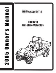
Parts diagram<br />
19 REV 46512-20110823<br />
ENGLISH 46512
46512 ENGLISH Parts List<br />
# Part Number Description Qty<br />
1 168FDE-2-G1 Engine 1<br />
2 ST02FD-02100011 Build Up (B) 1<br />
3 ST02FD-02100012 Build Up (A) 1<br />
4 ST02FD-02110000-2 .5 Rotor Comp 1<br />
5 ST02FD-02100005-2 .5 Flange BoltM8x233 1<br />
6 GB96 8 Washer 8mm 1<br />
7 GB7244 8 Lock Washer 8mm 1<br />
8 ST02FD-02120000-2 .5 Stator Assembly 1<br />
9 ST02FD-02100002-2 .5 Stator Cover 1<br />
10 ST02FD-02100003 End Cover 1<br />
11 ST02FD-02100001-2 .5 Flange Bolt M6x158 4<br />
12 GB97 .1 6 Washer 6mm 6<br />
13 GB93 6 Lock Washer 6mm 10<br />
14 ST02FD-02100009 Brush Assembly 1<br />
15 ST02FD-02100008 Plate Pinch 1<br />
16 GB93 5 Lock Washer 5 5<br />
17 GB5783 M5x16 Bolt M5x16 1<br />
18 GB97 .1 5 Washer 5mm 7<br />
19 GB5783 M5x16 Bolt M5x16 2<br />
20 AVR02-00000000 AVR 1<br />
21 GB16674 M5X16 Flange Bolt M5x16 2<br />
22 ST02FD-02100004(A) Generator End Cover 1<br />
23 GB16674 M5X12 Flange Bolt M5x12 2<br />
24 ST02FD-02100010 Terminal 1<br />
25 ST02FD-1150200 Muffler Stay (I) 1<br />
26 GB5789 M8X20 Flange Bolt M8x20 3<br />
27 ST02FD-1150100 Muffler Stay (II) 1<br />
28 GB5789 M6X12 Flange Bolt M6x12 12<br />
29 GB818 M5X15 Screw M5x15 2<br />
30 ST188FD-1100010-88 Spark Arrester Cover 1<br />
31 ST188FD-1180121 Spark Arrester Assembly 1<br />
32 ST168FD-1100000-G Muffler 1<br />
33 ST02FD-03030400(F) Muffler Cover 1<br />
34 GB6175 M8 NutM8 2<br />
35 GB93 8 Lock Washer 8mm 2<br />
36 GB848 8 Washer 8mm 2<br />
37 ST168F-1100200-G Muffler Gasket 1<br />
38 ST168FD-1090006 Air Cleaner stay 1<br />
39 GB5789 M6x8 Flange Bolt M6x8 1<br />
40 ST188FD-1070006A Clip 2<br />
41 168 .070011 .03 Fuel Line 1<br />
42 ST02FD-04160000 Fuel Cock 1<br />
43 GB819 M5X10 Screw M5x10 2<br />
44 ST02FD-04140000 Fuel Meter Assembly 1<br />
45 ST02FD-04120000-A Fuel Tank Cap 1<br />
46 ST02FD-04130000 Fuel Filter 1<br />
47 GB5789 M6x20 Flange Bolt M6x20 4<br />
48 ST02FD-04100014 Washer 6 .5mm 4<br />
49 ST02FD-04100010 Tank Rubber 4<br />
50 ST02FD-04110000(A) Fuel Tank 1<br />
51 ST188FD-1741002-C Handle sheath 1<br />
52 ST182FD-1151110-B Handle 1<br />
# Part Number Description Qty<br />
53 GB6177 M8 Nut M8 14<br />
54 GB5789 M8x45 Flange Bolt M8x45 2<br />
55 ST02FD-0184-2 .5(F) Frame 1<br />
56 ST02FD-1151300C-1 Bottom Rubber II 2<br />
57 ST02FD-1151300D-1 Bottom Rubber I 2<br />
58 GB6182 M10 Nut M10 2<br />
59 ST177FD-1152300(H) 8in Wheel 2<br />
60 ST02FD-03621001 Bush 10 .5x58 .5 2<br />
61 GB96 10 Flat Washer 10 2<br />
62 GB5782 M10x105 Bolt M10x105 2<br />
63 504 .200904 .00 Rubber Belt 1<br />
64 FM1290 9AH Battery 1<br />
65 ST188FD-1750002-C3 Battery Red Wire (+) 1<br />
66 ST05FD-03011112 Jacket 1<br />
67 ST168FD-1751002-A Jacket 2<br />
68 ST188FD-1750002-C7 Battery Black Wire (-) 1<br />
69 GB5789 M8x16 Flange Bolt M8x16 2<br />
70 ST05FD-03020301-60 Support Leg 1<br />
71 ST188FD-1743002-C Vibration Mount 2<br />
72 GB5789 M8x25 Flange Bolt M8x25 2<br />
73 ST02FD-02100013-2 .5 Earth Line 1<br />
74 GB6177 M6 Nut M6 1<br />
75 GB862 6 Washer 6mm 1<br />
76 ST188FD-1020001 Grommet 1<br />
77 GB823 M5x38 Screw M5x38 5<br />
78 504 .210002 .10 Control Box 1<br />
79 ST02FD-05612005 Indicator Light 1<br />
80 ST02FD-05612004 Button 1<br />
81 WR05-00000000 Remote Control 1<br />
82 GB823 M5x14 Screw M5x14 4<br />
83 EC02 Charger 1<br />
84 ST02FD-05302010 FUSE (10A) 1<br />
85 2P6(F) Control panel 1<br />
86 DP03-00000000 Trigitai meter III 1<br />
87 GB823 M4x14 Screw M4x14 8<br />
88 GB848 4 Washer 4mm 8<br />
89 GB859 4 Lock Washer 4mm 8<br />
90 29 .001 .00 Switch 1<br />
91 21 .001000 .02 Switch 1<br />
92 GB5781 M6x22 Bolt M6x22 1<br />
93 GB6175 M6 Nut M6 2<br />
94 ST02FD-05502020 Receptacle L5-30R 1<br />
95 GB6177 M4 Nut M4 6<br />
96 ST02FD-05502029 RV Receptacle 1<br />
97 ST02FD-05502023 5-20R Receptacle 1<br />
98 ST02FD-05302001-L25 AC .25A CIRCUIT BREAKERS 1<br />
99 ST02FD-05302001-L20 AC .20A CIRCUIT BREAKERS 1<br />
100 OV01-00000000-1 Transition 1<br />
101 504 .210002 .00 Control Box 1<br />
102 ST02FD-05212001 Build Up 1<br />
103 ST02FD-05212007 Conduit 1<br />
104 ST02FD-05212002 Build Up 1<br />
REV 46512-20110823 20
SPECIfICATIONS<br />
Engine Parts diagram<br />
21 REV 46512-20110823<br />
ENGLISH 46512
46512 ENGLISH<br />
# Part Number Description Qty<br />
1 GB5789--86-FB6-8 Flange Bolt 6X8 6<br />
2 ST160F--1061200 Recoil Starter Knob 1<br />
3 ST160F--1061100-Q Recoil Starter Comp 1<br />
4 ST160F--1061005 Recoil Starter Spring 1<br />
5 ST160F--1061009 Recoil Starter Rope 1<br />
6 ST160F--1061001-A Recoil Starter Reel 1<br />
7 ST188F--1060006 Return Spring 2<br />
8 ST188F--1060005 Starter Ratchet (Metal) 2<br />
9 GB5789--86-FB6-12 Flange Bolt M6X12 8<br />
10 ST188F--1060003 Ratchet Guide 1<br />
11 ST188F--1060004 Ratchet Guide Spring 1<br />
12 ST188F-1060002 Setting Screw 1<br />
13 168 .080100 .06(A) Fan Cover Comp 1<br />
14 ST160F--1050010 Nut M14 1<br />
15 ST160F--1060001 Start Hub 1<br />
16 ST168F--1080001 Cooling Fan 1<br />
17 ST168F--1120100-A Fly Wheel 1<br />
18 ST168F--1080200-A Side Place (II) 1<br />
19 ST168F--1030100 Oil Seal 2<br />
20 GB5789--86-FB6-15 Flange Bolt M6X15 4<br />
21 ST160F--1030003 Drain Plug Bolt 2<br />
22 ST160F--1030004 Drain Bolt Washer 2<br />
23 ST168F-2-1030012-G-E Crankcase (For USA) 1<br />
24 GB/T—276--94 Radial Ball Bearing 6205 2<br />
25 ST160F--1127000-A Oil Level Switch Assembly 1<br />
26 ST160F--1110108 Governor Washer (II) 1<br />
27 ST160F--1110101 Governor Weight Holder 1<br />
28 ST160F--1110102 Governor Weight Pin 2<br />
29 ST160F--1110104 Governor Shaft 1<br />
30 ST160F--1110103 Governor Holder Clip 1<br />
31 ST160F--1110107 Governor Weight 2<br />
32 ST188FD-1130004 Clip,String 2<br />
33 ST160F--1110105 Governor Cover 1<br />
34 ST168FD-2-1050001-A Crankshaft Comp 1<br />
35 ST168F--1030008-G Case Over Packing (No<br />
Asbestos)<br />
1<br />
36 ST160F--1030001-B Oil Filler Cap Assembly 1<br />
37 ST160F--1030002 Oil Filler Cap Packing 2<br />
38 GB5789--86-FB8-32 Flange Bolt 8X32 6<br />
39 ST168F--1110005 Throttle Return Spring 1<br />
40 ST168F--1110007 Governor Spring 1<br />
41 ST160F--1110003 Governor Arm 1<br />
42 GB6177--86 Nut M6 3<br />
43 ST160F--1110008 Lock Pin 1<br />
44 ST160F--1110001 Governor Arm Shaft 1<br />
45 ST168F--1110006 Governor Rod 1<br />
46 ST160F--1110004 Governor Arm Bolt 1<br />
47 GB5789--86-FB6-25 Flange Bolt 6X25 5<br />
48 ST160F--1123000-G Ignition 1<br />
49 152FMD--1001007 Dowel Pin 10X16 2<br />
50 GB5789--86-FB8-55 Flange Bolt 8X55 4<br />
51 ST168FD--1090200-G Air Cleaner Cover Comp 1<br />
52 ST168FD--1090004 Element 1<br />
53 ST168FD--1090003 Separator 1<br />
54 ST168FD--1090002 Air Cleaner Seal 1<br />
55 ST168FD--1090004 Air Cleaner Case Comp 1<br />
56 ST160F--1130003-CPE Carburetor Packing (No<br />
Asbestos)<br />
1<br />
# Part Number Description Qty<br />
57 ST168F--1130001 Carburetor Insulator 1<br />
58 ST168F--1130002-CPE Insulator Packing (No<br />
Asbestos)<br />
1<br />
59 ST168FD--1010001 Stud Bolt 6X90 2<br />
60 ST168F-2-1010100-G Cylinder Head Comp 1<br />
61 ST168F-2-1030009-G Cylinder Head Gasket 1<br />
62 ST168F--1040002 Intake Valve 1<br />
63 ST168F--1040006 Exhaust Valve 1<br />
64 ST168F-2-1040013 Valve Lifter 2<br />
65 ST168F-2-1041000 Camshaft Assembly 1<br />
66 ST168F--1030015-G Dowel Pin 9X14 2<br />
67 ST168FD--1111100 Control Assembly 1<br />
68 GB1099--79 Key 1<br />
69 ST168FD--1030007-G Crankcase Cover 1<br />
70 ST168F--1050100 Connecting Rod Comp 1<br />
71 ST168F--1050003 Piston Pin 1<br />
72 ST168F--1050004 Piston Pin Clip 2<br />
73 ST168F-2-1050005 Piston 1<br />
74 ST168F--1050007 First Ring Set 1<br />
ST168F--1050006 Second Ring Set 1<br />
ST168F--1050200 Ring Comp 1<br />
75 ST168F--1080002-G Shroud Comp (I) 1<br />
76 GB900--88 Stud Bolt 2<br />
77 ST168F--1040005 Push Rod 2<br />
78 ST168--1040014-A Oil Seal 2<br />
79 ST168F--1040027 Pivot Bolt 2<br />
80 ST168F--1040026 Valve Rocker Arm 1<br />
81 GB6177--86-N6 Nut M6 2<br />
82 ST168F--1040023 Exhaust Rocker 1<br />
83 ST160F--1020001 Breather Tube 1<br />
84 ST168F--1020100-C Head Over Comp 1<br />
85 ST160F--1020002-A Head Over Packing 1<br />
86 ST168F--1040024 Rectify Bolt 2<br />
87 ST168F--1040025 Locknut 2<br />
88 ST168F--1040022 Entrance Rocker 1<br />
89 ST168F--1040021 Rocker Axes 1<br />
90 ST160F--1040008 Valve Rotator 1<br />
91 ST160F--1040001 Intake Valve Spring Retainer 1<br />
92 ST160F--1040007 Exhaust Valve Spring Retainer 1<br />
93 ST160F--1040003 Valve Spring 2<br />
94 ST160F--1124000 Spark Plug 1<br />
95 468 .131000 .02 Carburetor 1<br />
96 0902 .130010 .00 Spring,Conn . 1<br />
97 168 .130015 .01 Connector,Starter 1<br />
98 ST168FD--1130004 Packing 2<br />
99 168 .130005 .01 Support,Stepper Motor 1<br />
100 188 .132200 .00 Stepper Motor Comp . 1<br />
101 GB818 M4×8 Screw M4X8 2<br />
102 0902 .132001 .00 Cover,Stepper Motor 1<br />
103 ST188F-1123000 Electrify Coil 1<br />
104 ST168F-1180104 Grommet 1<br />
105 ST168F-1180002 Wire Flat 1<br />
106 GB5789--86-FB6-29 Flange Bolt 6X29 1<br />
107 ST168F-1180001 Dowel Pin 8×10 2<br />
108 ST168F-1181100 Start Motor 1<br />
109 GB29 .2-88-FB5-16 Flange Bolt M5×16 2<br />
110 GB93-87-SW5 Lock Washer 5mm 2<br />
111 168 .125200 .01 Relay 1<br />
REV 46512-20110823 22
SPECIfICATIONS<br />
Wiring diagram<br />
23 REV 46512-20110823<br />
ENGLISH 46512
46512 ENGLISH<br />
Problem Cause Solution<br />
Generator will not start No fuel Add fuel<br />
Faulty spark plug Replace spark plug<br />
Unit loaded during start up Remove load from unit<br />
TROuBLESHOOTING<br />
Generator will not start; Low oil level Fill crankcase to the proper level<br />
Generator starts but runs roughly Place generator on a flat, level surface<br />
Choke in the wrong position . Adjust choke .<br />
Spark plug wire loose Attach wire to spark plug<br />
Generator shuts down during operation Out of fuel Fill fuel tank<br />
Generator cannot supply enough power or<br />
overheating<br />
Low oil level Fill crankcase to the proper level . Place<br />
generator on a flat, level surface<br />
Generator is overloaded Review load and adjust . See “Power<br />
Management”<br />
Insufficient ventilation Check for air restriction . Move to a well<br />
ventilated area<br />
No AC output Cable not properly connected Check all connections<br />
Connected device is defective Replace defective device<br />
Circuit breaker is open Reset circuit breaker<br />
Faulty brush assembly Replace brush assembly (Service Center)<br />
Faulty AVR (auto voltage regulator) Replace AVR (Service Center)<br />
Loose wiring Inspect and tighten wiring connections<br />
Other Contact the help line .<br />
Generator gallops Engine governor defective Contact the help line<br />
Repeated circuit breaker tripping Overload Review load and adjust . See “Power<br />
Management”<br />
Faulty cords or device Check for damaged, bare or frayed wires .<br />
Replace defective device<br />
for further technical support:<br />
Technical Service<br />
Mon – Fri 8:30 AM – 5:00 PM (PST/PDT)<br />
Toll Free: 1 (877) 338-0999<br />
tech@championpowerequipment .com<br />
REV 46512-20110823 24
WARRANTy<br />
25 REV 46512-20110823<br />
WARRANTy<br />
CHAMPION POWER EQUIPMENT<br />
2 YEAR LIMITED WARRANTY<br />
Warranty Qualifications<br />
Champion Power Equipment (CPE) will register this<br />
warranty upon receipt of your Warranty Registration Card<br />
and a copy of your sales receipt from one of CPE’s retail<br />
locations as proof of purchase .<br />
Please submit your warranty registration and your proof<br />
of purchase within ten (10) days of the date of purchase .<br />
Repair/Replacement Warranty<br />
CPE warrants to the original purchaser that the<br />
mechanical and electrical components will be free of<br />
defects in material and workmanship for a period of<br />
one year (parts and labor) and two years (parts) from<br />
the original date of purchase (90 days (parts and<br />
labor) and 180 days (parts) for commercial & industrial<br />
use) . Transportation charges on product submitted<br />
for repair or replacement under this warranty are the<br />
sole responsibility of the purchaser . This warranty only<br />
applies to the original purchaser and is not transferable .<br />
do Not Return The unit To The Place Of Purchase<br />
Contact CPE’s Technical Service and CPE will<br />
troubleshoot any issue via phone or e-mail . If the<br />
problem is not corrected by this method, CPE will, at its<br />
option, authorize evaluation, repair or replacement of the<br />
defective part or component at a CPE Service Center .<br />
CPE will provide you with a case number for warranty<br />
service . Please keep it for future reference . Repairs<br />
or replacements without prior authorization, or at an<br />
unauthorized repair facility, will not be covered by this<br />
warranty .<br />
Warranty Exclusions<br />
This warranty does not cover the following repairs and<br />
equipment:<br />
Normal Wear<br />
Generators need periodic parts and service to perform well .<br />
This warranty does not cover repair when normal use has<br />
exhausted the life of a part or the equipment as a whole .<br />
Installation, use and Maintenance<br />
This warranty will not apply to parts and/or labor if this<br />
generator is deemed to have been misused, neglected,<br />
involved in an accident, abused, loaded beyond the<br />
generator’s limits, modified, installed improperly or<br />
connected incorrectly to any electrical component .<br />
ENGLISH 46512<br />
Installation, use and Maintenance Cont’d.<br />
Normal maintenance such as spark plugs, air filters,<br />
adjustments, fuel system cleaning and obstruction due<br />
to buildup is not covered by this warranty .<br />
Other Exclusions<br />
This warranty excludes:<br />
– Cosmetic defects such as paint, decals, etc .<br />
– Wear items such as filter elements, o-rings, etc .<br />
– Accessory parts such as starting batteries, and<br />
storage covers .<br />
– Failures due to acts of God and other force majeure<br />
events beyond the manufacturer’s control .<br />
– Problems caused by parts that are not original<br />
Champion Power Equipment parts .<br />
This warranty does not apply to generators used for<br />
prime power in place of a utility .<br />
Limits of Implied Warranty and Consequential damage<br />
Champion Power Equipment disclaims any obligation to<br />
cover any loss of time, use of this product, freight, or<br />
any incidental or consequential claim by anyone from<br />
using this generator . THIS WARRANTY IS IN LIEU OF<br />
ALL OTHER WARRANTIES, EXPRESS OR IMPLIED,<br />
INCLUDING WARRANTIES OF MERCHANTABILITY OR<br />
FITNESS FOR A PARTICULAR PURPOSE .<br />
A unit provided as an exchange will be subject to the<br />
warranty of the original unit . The length of the warranty<br />
governing the exchanged unit will remain calculated by<br />
reference to the purchase date of the original unit .<br />
This warranty gives you certain legal rights which may<br />
change from state to state . Your state may also have<br />
other rights you may be entitled to that are not listed<br />
within this warranty .<br />
Contact Information<br />
Address<br />
Champion Power Equipment, Inc .<br />
Customer Service<br />
10006 Santa Fe Springs Rd .<br />
Santa Fe Springs, CA 90670<br />
www .championpowerequipment .com<br />
Customer Service<br />
Mon – Fri 8:30 AM – 5:00 PM (PST/PDT)<br />
Toll Free:1 (877) 338-0999<br />
Fax no .: 1 (562) 236-9429<br />
Technical Service<br />
Mon – Fri 8:30 AM – 5:00 PM (PST/PDT)<br />
Toll Free: 1 (877) 338-0999<br />
tech@championpowerequipment .com<br />
24/7 Tech Support: (562) 204-1188
46512 ENGLISH<br />
Champion Power Equipment, Inc (CPE),<br />
and the united States Environment Protection Agency (u.S. EPA.)<br />
Emission Control System Warranty<br />
Your Champion Power Equipment (CPE) engine complies with U .S . EPA emission regulations .<br />
yOuR WARRANTy RIGHTS ANd OBLIGATIONS:<br />
WARRANTy<br />
The US EPA AND CPE are pleased to explain the Federal Emission Control Systems Warranty on your 1997 and<br />
later small off-road engine . New engines must be designed, built and equipped, at the time of sale, to meet U .S .<br />
EPA regulations for small non-road engines . CPE must warrant the emission control system on your small off-road<br />
engine for the period of time listed below, provided there has been no abuse, neglect, unapproved modification, or<br />
improper maintenance of your small off-road engine .<br />
Your emission control system may include parts such as the carburetor, fuel-injection system, the ignition system,<br />
catalytic converter and fuel lines . Also included may be hoses, belts, connectors and other emission related<br />
assemblies . Where a warrantable condition exits, CPE will repair your small off-road engine at no cost to you<br />
including diagnosis, parts and labor .<br />
MANufACTuRER’S EMISSION CONTROL SySTEM WARRANTy COvERAGE:<br />
This emission control system is warranted for two years, subject to provisions set forth below . If, during the warranty<br />
period, emission related part on your engine is defective in materials or workmanship, the part will be repaired or<br />
replaced by CPE .<br />
OWNER WARRANTy RESPONSIBILITIES:<br />
As the small off-road engine owner, you are responsible for the performance of the required maintenance listed in<br />
your Owner’s Manual . CPE recommends that you retain all your receipts covering maintenance on your small off-road<br />
engine, but CPE cannot deny warranty solely for the lack of receipts or for your failure to ensure the performance of<br />
all scheduled maintenance .<br />
As the small off-road engine owner, you should however be aware that CPE may deny you warranty coverage<br />
if your small, off-road engine or a part has failed due to abuse, neglect, improper maintenance or unapproved<br />
modifications.<br />
You are responsible for presenting your small off-road engine to an Authorized CPE service outlet, CPE dealer or<br />
CPE, Santa Fe Springs, Ca . as soon as a problem exists . The warranty repairs should be completed in a reasonable<br />
amount of time, not to exceed 30 days .<br />
If you have any questions regarding your warranty rights and responsibilities, you should contact:<br />
Champion Power Equipment, Inc.<br />
ATTN: Customer Service<br />
10006 Santa Fe Springs Road<br />
Santa Fe Springs, CA 90670<br />
Tel: 1-877-338-0999<br />
The emission warranty is a defects warranty . Defects are judged on normal engine performance . The warranty is not<br />
related to an in-use emission test .<br />
REV 46512-20110823 26
WARRANTy<br />
EMISSION CONTROL SySTEM WARRANTy<br />
27 REV 46512-20110823<br />
ENGLISH 46512<br />
The following are specific provisions relative to your Emission Control System Warranty Coverage.<br />
Emission Control System Warranty (ECS Warranty) for 1997 and later model year engines):<br />
1. APPLICABILITY: This warranty shall apply to 1997 and later model year engines) . The ECS Warranty Period shall<br />
begin on the date the new engine or equipment is delivered to its original, end-use purchaser, and shall continue<br />
for 24 consecutive months thereafter .<br />
2. GENERAL EMISSIONS WARRANTY COVERAGE<br />
CPE warrants to the original, end-use purchaser of the new engine or equipment and to each subsequent<br />
purchaser that each of its small off-road engines is:<br />
a . Designed, built and equipped so as to conform at the time of sale with applicable regulations under section<br />
213 of the Clean Air Ac, as amended, 42 U .S .C . 7401 et seq .<br />
b . Free from defects in materials and workmanship that cause the failure of a warranted part to be identical in all<br />
material respects to the part as described in the engine manufacturer’s application for certification for a period<br />
of two years .<br />
3. THE WARRANTY ON EMISSION-RELATED PARTS WILL BE INTERPRETED AS FOLLOWS:<br />
a . Any warranted part that is not scheduled for replacement as required maintenance in the Owners Manual shall<br />
be warranted for the ECS Warranty Period . If any such part fails during the ECS Warranty Period, it shall be<br />
repaired or replaced by CPE according to Subsection “d” below . Any such part repaired or replaced under the<br />
ECS Warranty shall be warranted for any remainder of the ECS Warranty Period .<br />
b . Any warranted, emissions-related part which is scheduled only for regular inspection as specified in the Owners<br />
Manual shall be warranted for the ECS Warranty Period . A statement in such written instructions to the effect<br />
of “repair or replace as necessary”, shall not reduce the ECS Warranty Period . Any such part repaired or<br />
replaced under the ECS Warranty shall be warranted for the remainder of the ECS Warranty Period .<br />
c . Any warranted, emissions-related part which is scheduled for replacement as required maintenance in the<br />
Owner’s Manual shall be warranted for the period of time prior to the first scheduled replacement point for<br />
that part . If the part fails prior to the first scheduled replacement, the part shall be repaired or replaced<br />
by CPE according to Subsection “d” below . Any such emissions-related part repaired or replaced under the<br />
ECS Warranty, shall be warranted for the remainder of the ECS Warranty Period prior to the first scheduled<br />
replacement point for such emissions-related part .<br />
d . Repair or replacement of any warranted, emissions-related part under this ECS Warranty shall be performed at<br />
no charge to the owner at a CPE Authorized Service Outlet .<br />
e . The owner shall not be charged for diagnostic labor which leads to the determination that a part covered by the<br />
ECS Warranty is in fact defective, provided that such diagnostic work is performed at a CPE Authorized Service<br />
Outlet .<br />
f . CPE shall be liable for damages to other original engine components or approved modifications proximately<br />
caused by a failure under warranty of an emission-related part covered by the ECS Warranty .<br />
g . Throughout the ECS Warranty Period, CPE shall maintain a supply of warranted emission-related parts<br />
sufficient to meet the expected demand for such emission-related parts .<br />
h . Any CPE Authorized and approved emission-related replacement part may be used in the performance of any<br />
ECS Warranty maintenance or repair and will be provided without charge to the owner . Such use shall not<br />
reduce CPE’s warranty obligation .<br />
i . Unapproved add-on or modified parts may not be used to modify or repair a CPE engine . Such use voids this<br />
ECS Warranty and shall be sufficient grounds for disallowing an ECS Warranty claim . CPE shall not be liable<br />
hereunder for failures of any warranted parts of a CPE engine caused by the use of such an unapproved add-on<br />
or modified part .
46512 ENGLISH<br />
WARRANTy<br />
EMISSION-RELATEd PARTS INCLudE THE fOLLOWING (using those portions of the list applicable to the engine):<br />
Systems covered by this warranty Parts Description<br />
Fuel Metering System Fuel regulator, Carburetor and internal parts<br />
Air Induction System Air cleaner, Intake manifold<br />
Ignition System Spark plug and parts, Magneto ignition system<br />
Exhaust System Exhaust manifold, catalytic converter<br />
Miscellaneous Parts Tubing, Fittings, Seals, Gaskets, and Clamps associated with these<br />
listed systems<br />
TO OBTAIN WARRANTY SERVICE:<br />
You must take your CPE engine or the product on which it is installed, along with your warranty registration card or<br />
other proof of original purchase date, at your expense, to any Champion Power Equipment dealer who is authorized<br />
by Champion Power Equipment, Inc . to sell and service that CPE product during his normal business hours . Claims<br />
for repair or adjustment found to be caused solely by defects in material or workmanship will not be denied because<br />
the engine was not properly maintained and used .<br />
If you have any questions regarding your warranty rights and responsibilities, or to obtain warranty service, please<br />
write or call the Customer service of Champion Power Equipment, Inc.:<br />
Champion Power Equipment, Inc.<br />
ATTN: Customer Service<br />
10006 Santa Fe Springs Road<br />
Santa Fe Springs, CA 90670<br />
Tel: 1-877-338-0999<br />
REV 46512-20110823 28