Multi-Carrier and Spread Spectrum Systems: From OFDM and MC ...
Multi-Carrier and Spread Spectrum Systems: From OFDM and MC ...
Multi-Carrier and Spread Spectrum Systems: From OFDM and MC ...
- No tags were found...

Create successful ePaper yourself
Turn your PDF publications into a flip-book with our unique Google optimized e-Paper software.
<strong>Multi</strong>-<strong>Carrier</strong> <strong>and</strong><strong>Spread</strong> <strong>Spectrum</strong><strong>Systems</strong><strong>From</strong> <strong>OFDM</strong> <strong>and</strong> <strong>MC</strong>-CDMA to LTE <strong>and</strong>WiMAXSecond EditionK. FazelEricsson GmbH, Germany<strong>and</strong>S. KaiserDOCOMO Communications Laboratories Europe GmbH, GermanyA John Wiley <strong>and</strong> Sons, Ltd, Publication
<strong>Multi</strong>-<strong>Carrier</strong> <strong>and</strong><strong>Spread</strong> <strong>Spectrum</strong><strong>Systems</strong><strong>From</strong> <strong>OFDM</strong> <strong>and</strong> <strong>MC</strong>-CDMA to LTE <strong>and</strong>WiMAXSecond EditionK. FazelEricsson GmbH, Germany<strong>and</strong>S. KaiserDOCOMO Communications Laboratories Europe GmbH, GermanyA John Wiley <strong>and</strong> Sons, Ltd, Publication
This edition first published 2008© 2008 John Wiley & Sons, LtdRegistered office John Wiley & Sons Ltd, The Atrium,Southern Gate, Chichester,West Sussex PO19 8SQ, United KingdomFor details of our global editorial offices, for customer services <strong>and</strong> for information about how to apply forpermission to reuse the copyright material in this book please see our website at www.wileyeurope.com orwww.wiley.com.The right of the author to be identified as the author of this work has been asserted in accordance with theCopyright, Designs <strong>and</strong> Patents Act 1988.All rights reserved. No part of this publication may be reproduced, stored in a retrieval system, or transmitted, inany form or by any means, electronic, mechanical, photocopying, recording or otherwise, except as permitted bythe UK Copyright, Designs <strong>and</strong> Patents Act 1988, without the prior permission of the publisher.Wiley also publishes its books in a variety of electronic formats. Some content that appears in print may not beavailable in electronic books.Designations used by companies to distinguish their products are often claimed as trademarks. All br<strong>and</strong> names<strong>and</strong> product names used in this book are trade names, service marks, trademarks or registered trademarks of theirrespective owners. The publisher is not associated with any product or vendor mentioned in this book. Thispublication is designed to provide accurate <strong>and</strong> authoritative information in regard to the subject matter covered.It is sold on the underst<strong>and</strong>ing that the publisher is not engaged in rendering professional services. If professionaladvice or other expert assistance is required, the services of a competent professional should be sought.Library of Congress Cataloging-in-Publication DataFazel, Khaled.<strong>Multi</strong>-carrier <strong>and</strong> spread spectrum systems: from <strong>OFDM</strong> <strong>and</strong> <strong>MC</strong>-CDMA to LTE <strong>and</strong>WiMAX / K. Fazel, S. Kaiser. – 2nd ed.p. cm.Includes bibliographical references <strong>and</strong> index.ISBN 978-0-470-99821-21. <strong>Spread</strong> spectrum communications. 2. <strong>Multi</strong>plexing. I. Kaiser, Stefan, 1960–II. Title.TK5103.45.F39 2008621.382–dc222008031728A catalogue record for this book is available from the British Library.ISBN 978-0-470-99821-2Typeset by Laserwords Private Limited, Chennai, IndiaPrinted <strong>and</strong> bound in Singapore by Markono Print Media Pte, Ltd.
tomy parents, my wife Miriam,my daughters Sarah, Sophia, <strong>and</strong> Susanna(K.F.)my wife Susanna,my sons Lukas <strong>and</strong> Philipp <strong>and</strong> my daughter Anna(S.K.)
Contentsix4.3.2 One-Dimensional Channel Estimation 1594.3.3 Filter Design 1594.3.4 Implementation Issues 1604.3.5 Performance Analysis 1624.3.6 Time Domain Channel Estimation 1684.3.7 Decision Directed Channel Estimation 1684.3.8 Blind <strong>and</strong> Semi-Blind Channel Estimation 1694.3.9 Channel Estimation in <strong>MC</strong>-SS <strong>Systems</strong> 1704.3.10 Channel Estimation in MIMO-<strong>OFDM</strong> <strong>Systems</strong> 1744.4 Channel Coding <strong>and</strong> Decoding 1744.4.1 Punctured Convolutional Coding 1754.4.2 Concatenated Convolutional <strong>and</strong> Reed Solomon Coding 1754.4.3 Turbo Coding 1784.4.4 Low Density Parity Check (LDPC) Codes 1824.4.5 <strong>OFDM</strong> with Code Division <strong>Multi</strong>plexing: <strong>OFDM</strong>-CDM 1864.5 Signal Constellation, Mapping, De-Mapping, <strong>and</strong> Equalization 1874.5.1 Signal Constellation <strong>and</strong> Mapping 1874.5.2 Equalization <strong>and</strong> De-Mapping 1894.6 Adaptive Techniques in <strong>Multi</strong>-<strong>Carrier</strong> Transmission 1904.6.1 Nulling of Weak Sub-<strong>Carrier</strong>s 1914.6.2 Adaptive Channel Coding <strong>and</strong> Modulation 1914.6.3 Adaptive Power Control 1924.7 RF Issues 1924.7.1 Phase Noise 1934.7.2 Non-linearities 1974.7.3 Narrowb<strong>and</strong> Interference Rejection in <strong>MC</strong>-CDMA 2064.7.4 Link Budget Evaluation 208References 2105 Applications 2155.1 Introduction 2155.2 3GPP Long Term Evolution (LTE) 2185.2.1 Introduction 2185.2.2 Requirements on LTE 2195.2.3 Radio Access Network (RAN) Architecture 2205.2.4 Radio Protocol Architecture 2205.2.5 Downlink Transmission Scheme 2215.2.6 Uplink Transmission Scheme 2275.2.7 Physical Layer Procedures 2315.2.8 Supported B<strong>and</strong>widths 2325.2.9 Frequency B<strong>and</strong>s 2335.2.10 <strong>Spectrum</strong> Masks 2345.2.11 Performance 2355.3 WiMAX 2375.3.1 Scope 2375.3.2 <strong>From</strong> IEEE 802.16x <strong>and</strong> ETSI BRAN HIPERMAN Towards WiMAX 2395.3.3 System Architecture 2425.3.4 Broadb<strong>and</strong> Wireless Access St<strong>and</strong>ards: HIPERMAN <strong>and</strong> IEEE 802.16x 2435.3.5 Transmit Diversity / MIMO in WiMAX 2635.3.6 WiMAX Profiles 267
xContents5.3.7 Performance 2715.4 Future Mobile Communications Concepts <strong>and</strong> Field Trials 2765.4.1 Objectives 2765.4.2 Network Topology <strong>and</strong> Basic Concept 2765.4.3 Experiments <strong>and</strong> Field Trials 2765.4.4 VSF-OFCDM Access Scheme 2775.4.5 System Parameters 2785.5 Wireless Local Area Networks 2835.5.1 Network Topology 2835.5.2 Channel Characteristics 2835.5.3 IEEE 802.11a 2845.5.4 Transmission Performance 2865.6 Interaction Channel for DVB-T: DVB-RCT 2875.6.1 Network Topology 2885.6.2 Channel Characteristics 2905.6.3 <strong>Multi</strong>-<strong>Carrier</strong> Uplink Transmission 2905.6.4 Transmission Performance 296References 2976 Additional Techniques for Capacity <strong>and</strong> Flexibility Enhancement 3016.1 Introduction 3016.2 MIMO Overview 3026.2.1 BLAST Architecture 3036.2.2 Space–Time Coding 3046.2.3 Achievable Capacity 3076.3 Diversity Techniques for <strong>Multi</strong>-<strong>Carrier</strong> Transmission 3086.3.1 Transmit Diversity 3086.3.2 Receive Diversity 3136.3.3 Transmit/Receive Diversity Performance Analysis 3146.3.4 Space–Frequency Block Codes (SFBC) 3176.3.5 SFBC Performance Analysis 3196.4 Spatial Pre-Coding for <strong>Multi</strong>-<strong>Carrier</strong> Transmission 3216.4.1 Spatial Phase Coding (SPC) 3236.4.2 Selection Diversity (SD) 3256.4.3 Equal Gain Transmission (EGT) 3266.4.4 Maximum Ratio Transmission (MRT) 3266.4.5 Performance Analysis 3266.5 Software-Defined Radio 3316.5.1 General 3326.5.2 Basic Concept 3336.5.3 <strong>MC</strong>-CDMA-Based Software-Defined Radio 335References 337Definitions, Abbreviations, <strong>and</strong> Symbols 339Definitions 339Abbreviations 342Symbols 349Index 353
ForewordThis book discusses multi-carrier modulation <strong>and</strong> spread spectrum techniques, recognizedas the most promising c<strong>and</strong>idate modulation methods for the 4th generation (4G) ofmobile communications systems. The authors of this book were the first to propose <strong>MC</strong>-CDMA for the next generation of mobile communications, <strong>and</strong> are still continuing theircontribution towards beyond 3G. Considering the requirements of 4G systems, multicarrier<strong>and</strong> spread spectrum systems appear to be the most suitable as they provide higherflexibility, higher transmission rates, <strong>and</strong> frequency usage efficiency. This is the first bookon these methods, providing the reader with the fundamentals of the technologies involved<strong>and</strong> the related applications.The book deals with the principles through definitions of basic technologies <strong>and</strong> themultipath channel over which the signals are transmitted. It defines <strong>MC</strong>-CDMA as a frequencyPN pattern <strong>and</strong> <strong>MC</strong>-DS-CDMA as a straight extension of DS-CDMA; <strong>and</strong> arguesthat these twin asymmetric technologies are most suitable for 4G since <strong>MC</strong>-CDMA issuitable for the downlink <strong>and</strong> <strong>MC</strong>-DS-CDMA is suitable for the uplink in the cellularsystems. Although <strong>MC</strong>-CDMA performs better than <strong>MC</strong>-DS-CDMA, it needs chip synchronizationbetween users, <strong>and</strong> is therefore difficult to deploy in the uplink. Thus, forthis asymmetric structure it is very important to underst<strong>and</strong> the multi-carrier spread spectrummethods. Hybrid multiple access schemes like <strong>Multi</strong>-<strong>Carrier</strong> FDMA, <strong>Multi</strong>-<strong>Carrier</strong>TDMA, <strong>and</strong> Ultra Wide B<strong>and</strong> systems are discussed as more extended systems. Implementationissues, including synchronization, channel estimation, <strong>and</strong> RF issues, are alsodiscussed in depth. Wireless local area networks, broadcasting transmission, <strong>and</strong> cellularmobile radio are shown to realize seamless networking for 4G. Although cellular systemshave not yet been combined with other wireless networks, different wireless systemsshould be seamlessly combined. The last part of this book discusses capacity <strong>and</strong> flexibilityenhancement technologies like diversity techniques, space–time/frequency coding,<strong>and</strong> SDR (Software Defined Radio).This book greatly assists not only theoretical researchers but also practicing engineersof the next generation of mobile communications systems.Prof. Masao NakagawaDepartment of Information <strong>and</strong> Computer ScienceKeio University, Japan
Preface (Second Edition)The dem<strong>and</strong> for high data rate wireless multi-media applications has increased significantlyin the past few years. The wireless user’s pressure towards faster communications, no matterwhether mobile, nomadic, or fixed positioned, without extra cost is nowadays a reality.Finding an optimal solution for this dilemma is challenging, not only for manufacturersbut also for network operators. The recent strategy followed within ETSI 3GPP LTE<strong>and</strong> the WiMAX Forum was an evolutionary concept, especially for mobile applications.Both have adopted a new PHY layer multi-carrier transmission with a MIMO scheme, apromising combination offering a high data rate at low cost.Since the first edition of our book in 2003, the application field of multi-carrier transmissionin mobile communications has been extended in two important areas: 3GPP LongTerm Evolution (LTE) <strong>and</strong> WiMAX. Parallel to that, the topic of MIMO in conjunctionwith <strong>OFDM</strong> has taken further steps.New experiences gained during the above-mentioned st<strong>and</strong>ardization activities <strong>and</strong> thelatest research results on MIMO-<strong>OFDM</strong> gave us sufficient background <strong>and</strong> material toextend this book towards its Second Edition, i.e. covering new application fields (LTE<strong>and</strong> WiMAX) <strong>and</strong> new trends on MIMO-<strong>OFDM</strong> technology. We hope that the SecondEdition of this book will further contribute to a better underst<strong>and</strong>ing of the principlesof multi-carrier transmission <strong>and</strong> of its variety of application fields, <strong>and</strong>, finally, it maymotivate research toward new developments.K. Fazel, S. Kaiser
Preface (First Edition)Nowadays, multi-carrier transmission is considered to be an old concept. Its basic ideagoes back to the mid-1960s. Nevertheless, behind any old technique there are alwaysmany simple <strong>and</strong> exciting ideas, the terrain for further developments of new efficientschemes.Our first experience with the simple <strong>and</strong> exciting idea of <strong>OFDM</strong> started in early 1991with digital audio broadcasting (DAB). <strong>From</strong> 1992, our active participation in severalresearch programmes on digital terrestrial TV broadcasting (DVB-T) gave us furtheropportunities to look at several aspects of the <strong>OFDM</strong> technique with its new advanced digitalimplementation possibilities. The experience gained from the joined specification ofseveral <strong>OFDM</strong>-based demonstrators within the German HDTV-T <strong>and</strong> the EU-RACE dTTbresearch projects served as a basis for our commitment in 1995 to the final specificationsof the DVB-T st<strong>and</strong>ard, relaying on the multi-carrier transmission technique.Parallel to the HDTV-T <strong>and</strong> the dTTb projects, our further involvement from 1993 inthe EU-RACE CODIT project, with the scope of building a first European 3G testbed,following the DS-CDMA scheme, inspired our interest in another old technique, spreadspectrum, being as impressive as multi-carrier transmission. Although the final choice ofthe specification of the CODIT testbed was based on wideb<strong>and</strong> CDMA, an alternativemultiple-access scheme exploiting the new idea of combining <strong>OFDM</strong> with spread spectrum,i.e. multi-carrier spread spectrum (<strong>MC</strong>-SS), was considered as a potential c<strong>and</strong>idate<strong>and</strong> discussed widely during the definition phase of the first testbed.Our strong belief in the efficiency <strong>and</strong> flexibility of multi-carrier spread spectrum comparedto W-CDMA for applications such as beyond 3G motivated us, from the introductionof this new multiple access scheme at PIMRC ’93, to further contribute to it, <strong>and</strong> toinvestigate different corresponding system level aspects.Due to the recognition of the merits of this combination by well-known internationalexperts, since the PIMRC ’93 conference, <strong>MC</strong>-SS has rapidly become one of the mostwidespread independent research topics in the field of mobile radio communications.The growing success of our organized series of international workshops on <strong>MC</strong>-SS since1997, the large number of technical sessions devoted in international conferences to multicarriertransmission, <strong>and</strong> the several special editions of the European Transactions onTelecommunications (ETT) on <strong>MC</strong>-SS highlight the importance of this combination forfuture wireless communications.Several <strong>MC</strong>-CDMA demonstrators, e.g. one of the first built within DLR <strong>and</strong> its livedemonstration during the 3rd international <strong>MC</strong>-SS workshop, a multitude of recent internationalresearch programmes like the research collaboration between DOCOMO Euro-Labs
xviPreface (First Edition)<strong>and</strong> DLR on the design of a future broadb<strong>and</strong> air interface or the EU-IST MATRICE,4MORE, <strong>and</strong> WINNER projects, <strong>and</strong> especially the NTT DOCOMO research initiative tobuild a demonstrator for beyond 3G systems based on the multi-carrier spread spectrumtechnique, emphasize the commitment of the international research community to thisnew topic.Our experience gained during the above-mentioned research programmes, our currentinvolvement in the ETSI-BRAN project, our yearly seminars organized within Carl GranzGesellschaft (CCG) on digital TV broadcasting <strong>and</strong> on WLAN/WLL have given us sufficientbackground knowledge <strong>and</strong> material to take this initiative to collect in this bookmost of the important aspects on multi-carrier, spread spectrum, <strong>and</strong> multi-carrier spreadspectrum systems.We hope that this book will contribute to a better underst<strong>and</strong>ing of the principlesof multi-carrier <strong>and</strong> spread spectrum <strong>and</strong> may motivate further investigation into <strong>and</strong>development of this new technology.K. Fazel, S. Kaiser
AcknowledgementsThe authors would like to express their sincere thanks to Prof. M. Nakagawa from KeioUniversity, Japan, for writing the foreword. Many thanks go to Dr. H. Atarashi, Dr. N.Maeda, Dr. S. Abeta, <strong>and</strong> Dr. M. Sawahashi from NTT DOCOMO for providing us withmaterial regarding their multi-carrier spread spectrum activities. Many thanks also for thesupport of Dr. E. Auer from Ericsson GmbH <strong>and</strong> for helpful technical discussions withmembers of the DOCOMO Euro-Labs <strong>and</strong> the Mobile Radio Transmission Group fromDLR. Further thanks also go to Dr. I. Cosovic from DOCOMO Euro-Labs who providedus with results for the uplink, especially with pre-equalization.K. Fazel, S. Kaiser
IntroductionThe main feature of the next-generation wireless systems will be the convergence ofmult-media services such as speech, audio, video, image, <strong>and</strong> data. This implies that afuture wireless terminal, by guaranteeing high speed data, will be able to connect to differentnetworks in order to support various services: switched traffic, IP data packets,<strong>and</strong> broadb<strong>and</strong> streaming services such as video. The development of wireless terminalswith generic protocols <strong>and</strong> multiple physical layers or software-defined radio interfacesis expected to allow users to seamlessly switch access between existing <strong>and</strong> future st<strong>and</strong>ards.The rapid increase in the number of wireless mobile terminal subscribers, which currentlyexceeds 3 billion users, highlights the importance of wireless communications inthis new millennium. This revolution in the information society has taken place, especiallyin Europe <strong>and</strong> Japan through a continuous evolution of emerging st<strong>and</strong>ards <strong>and</strong> productsby keeping a seamless strategy for the choice of solutions <strong>and</strong> parameters. The continuousadaptation of wireless technologies to the user’s rapidly changing dem<strong>and</strong>s has been oneof the main drivers for the success of this evolution. Therefore, the worldwide wirelessaccess system is <strong>and</strong> will continue to be characterized by a heterogeneous multitude ofst<strong>and</strong>ards <strong>and</strong> systems. This plethora of wireless communication systems is not limited tocellular mobile telecommunication systems such as GSM, IS-95, D-AMPS, PDC, CDMA-2000, WCDMA/UMTS, HSDPA, HSUPA, or 3GPP LTE, but also includes wireless localarea networks (WLANs), e.g. IEEE 802.11a/n <strong>and</strong> Bluetooth, broadb<strong>and</strong> wireless access(BWA) such as WiMAX systems with their first goal to introduce wireless local loops(WLL) services based on ETSI HIPERMAN <strong>and</strong> IEEE 802.16x st<strong>and</strong>ards <strong>and</strong> in a futurestep to support full cellular mobility, as well as broadcast systems such as digital audiobroadcasting (DAB) <strong>and</strong> digital video broadcasting (DVB-T <strong>and</strong> DVB-H).These trends have accelerated since the beginning of the 1990s with the replacementof the first-generation analogue mobile networks by the current second-generation (2G)systems (GSM, IS-95, D-AMPS, <strong>and</strong> PDC), which opened the door for a fully digitalnetwork. This evolution is continuing with the deployment of the third-generation (3G)systems namely WCDMA/UMTS, HSDPA, HSUPA, <strong>and</strong> CDMA-2000, referred to asIMT 2000. The 3GPP Long Term Evolution (LTE) st<strong>and</strong>ard with significantly higher datarates than in 3G systems can be considered as 3G evolution. In the meantime, the researchcommunity is focusing its activity towards the next-generation mobile systems beyond 3G(B3G), referred to as IMT-Advanced or fourth-generation (4G) systems, with even more<strong>Multi</strong>-<strong>Carrier</strong> <strong>and</strong> <strong>Spread</strong> <strong>Spectrum</strong> <strong>Systems</strong> Second Edition K. Fazel <strong>and</strong> S. Kaiser© 2008 John Wiley & Sons, Ltd
2 Introductionambitious technological challenges. Note that especially within the WINNER Project [55],which is a European research project, partly funded by the European Commission, innovativesolutions for IMT-Advanced are targeted. The WINNER concept covers data ratesthat are higher than with LTE. The WINNER concept is described in References [54]<strong>and</strong> [55].The primary goal of next-generation wireless systems (IMT-Advanced) will not onlybe the introduction of new technologies to cover the need for higher data rates <strong>and</strong> newservices but also the integration of existing technologies into a common platform. Hence,the selection of a generic air interface for future-generation wireless systems will be ofgreat importance. Although the exact requirements for IMT-Advanced have not yet beencommonly defined, its new air interface will fulfill at least the following requirements:– generic architecture, enabling the integration of existing technologies;– high spectral efficiency, offering higher data rates in a given scarce spectrum;– high scalability, designing different cell configurations (hot spot, ad hoc) forimproved coverage;– high adaptability <strong>and</strong> reconfigurability, supporting different st<strong>and</strong>ards <strong>and</strong> technologies;– low latency, allowing better service quality;– low cost, enabling a rapid market introduction; <strong>and</strong>– future proof, opening the door for new technologies.<strong>From</strong> 2G to 3G <strong>and</strong> B3G <strong>Multi</strong>ple Access Schemes2G wireless systems are mainly characterized by the transition from analogue to a fullydigital technology <strong>and</strong> comprise the GSM, IS-95, PDC, <strong>and</strong> D-AMPS st<strong>and</strong>ards.Work on the pan-European digital cellular st<strong>and</strong>ard Global System for Mobile Communications(GSM) started in 1982 [18, 39], where now it accounts for about 85 % of theworld mobile market. In 1989, the technical specifications of GSM were approved by theEuropean Telecommunication St<strong>and</strong>ard Institute (ETSI), where its commercial successbegan in 1993. Although GSM is optimized for circuit-switched services such as voice,it offers low rate data services up to 14.4 kbit/s. High speed data services with up to171.2 kbit/s are possible with the enhancement of the GSM st<strong>and</strong>ard, namely the GeneralPacket Radio Service (GPRS), by assigning multiple time slots to one link. GPRSuses the same modulation, frequency b<strong>and</strong>, <strong>and</strong> frame structure as GSM. The EnhancedData Rate for Global Evolution (EDGE) [6] system, which further improves the datarate up to 384 kbit/s, introduces a new spectrum efficient modulation scheme. Parallelto GSM, the American IS-95 st<strong>and</strong>ard [45] (recently renamed cdmaOne) was approvedby the Telecommunication Industry Association (TIA) in 1993, where its first commercialapplication started in 1995. Like GSM, the first version of this st<strong>and</strong>ard (IS-95A)offers data services up to 14.4 kbit/s. In its second version (IS-95B) up to 64 kbit/s arepossible.Two further 2G mobile radio systems were introduced: Digital Advanced Mobile PhoneServices (D-AMPS/IS-136), called TDMA in the USA, <strong>and</strong> the Personal Digital Cellular(PDC) in Japan [30]. The most convincing example of high speed mobile Internet services,called i-mode, was introduced 1999 in Japan in the PDC system. The high increase in
Introduction 3customers <strong>and</strong> traffic in the PDC system urged the Japanese to start the first 3G WCDMAnetwork in 2001 under the name FOMA.Trends toward more capacity for mobile receivers, new multimedia services, new frequencies,<strong>and</strong> new technologies have motivated the idea of 3G systems. A unique internationalst<strong>and</strong>ard was targeted, referred to as International Mobile Telecommunications 2000(IMT-2000), realizing a new generation of mobile communications technology for a worldin which personal communication services will dominate. The objectives of the thirdgenerationst<strong>and</strong>ards, namely WCDMA/UMTS [1], HSDPA [2], HSUPA [3], <strong>and</strong> CDMA-2000 [46] went far beyond the second-generation systems, especially with respect to:– the wide range of multimedia services (speech, audio, image, video, data) <strong>and</strong> bitrates (up to 14.4 Mbit/s for indoor <strong>and</strong> hot spot applications);– the high quality of service requirements (better speech/image quality, lower bit errorrate (BER), higher number of active users);– operation in mixed cell scenarios (macro, micro, pico);– operation in different environments (indoor/outdoor, business/domestic, cellular/cordless); <strong>and</strong>– finally, flexibility in frequency (variable b<strong>and</strong>width), in data rate (variable), <strong>and</strong> inradio resource management (variable power/channel allocation).The commonly used multiple access schemes for second- <strong>and</strong> third-generation wirelessmobile communication systems are based on either time division multiple access (TDMA)or code division multiple access (CDMA), or the combined access schemes in conjunctionwith an additional frequency division multiple access (FDMA) component:– The GSM st<strong>and</strong>ard, employed in the 900 MHz <strong>and</strong> 1800 MHz b<strong>and</strong>s, first dividesthe allocated b<strong>and</strong>width into 200 kHz FDMA sub-channels. In each sub-channel, upto eight users share eight time slots in a TDMA manner [39].– In the IS-95 st<strong>and</strong>ard up to 64 users share the 1.25 MHz channel by CDMA [45].The system is used in the 850 MHz <strong>and</strong> 1900 MHz b<strong>and</strong>s.– The aim of D-AMPS (TDMA IS-136) is to coexist with the analogue AMPS, wherethe 30 kHz channel of AMPS is divided into three channels, allowing three users toshare a single radio channel by allocating unique time slots to each user [29].– The 3G st<strong>and</strong>ards (WCDMA/UMTS <strong>and</strong> CDMA-2000) adopted by ITU are bothbased on CDMA [1, 46]. For UMTS, the CDMA-FDD mode, which is known aswideb<strong>and</strong> CDMA (WCDMA), employs separate 5 MHz channels for both the uplink<strong>and</strong> downlink directions. Within the 5 MHz b<strong>and</strong>width, each user is separated by aspecific code, resulting in an end-user data rate of theoretically up to 2 Mbit/s per carrier.Further evolutions of WCDMA are the extensions towards high speed downlinkpacket access (HSDPA) with data rates of up to 14.4 Mbit/s <strong>and</strong> of high speed uplinkpacket access (HSUPA) with data rates of up to 5.74 Mbit/s. These improvementsare obtained by introducing higher order modulation schemes, channel-dependentscheduling, <strong>and</strong> hybrid ARQ (HARQ) with soft combining together with multiplecode allocation. The downlink additionally supports adaptive coding <strong>and</strong> modulation.The set of HSDPA <strong>and</strong> HSUPA is termed high speed packet access (HSPA) [2, 3].
4 IntroductionTables 1 <strong>and</strong> 2 summarize the key characteristics of 2G <strong>and</strong> 3G mobile communicationsystems.Besides tremendous developments in mobile communication systems, in public <strong>and</strong>private environments, operators are offering wireless services using WLANs in selectedspots such as hotels, train stations, airports, <strong>and</strong> conference rooms. As Table 3 shows,there is a similar objective to go higher in data rates with WLANs, where as multipleaccess schemes TDMA or CDMA are employed [32].FDMA, TDMA, <strong>and</strong> CDMA are obtained if the transmission b<strong>and</strong>width, the transmissiontime, or the spreading code is related to the different users, respectively [5].Table 1Main parameters of 2G mobile radio systemsParameter2G systemsGSM IS-95/cdmaOne PDC(+ GPRS, EDGE) (+ CDMA-2000)<strong>Carrier</strong> frequencies 900 MHz 850 MHz 850 MHz1800 MHz 1900 MHz 1500 MHzPeak data rate 64 kbit/s 64 kbit/s 28.8 kbit/s171.2 kbit/s (GPRS) 144 kbit/s384 kbit/s (EDGE) (CDMA-2000 1x)<strong>Multi</strong>ple access TDMA CDMA TDMAServices Voice, low rate data Voice, low rate data Voice, low rate dataTable 2Main parameters of 3G <strong>and</strong> B3G mobile radio systemsParameterWCDMA/UMTS(+ HSDPA, HSUPA)3G <strong>and</strong> B3G systemsEV-DO Rev. 0(+ Rev. A, Rev. B)<strong>Carrier</strong> frequencies 2 GHz 450 MHz, 800 MHz,2 GHz3GPP long termevolution (LTE)IMT b<strong>and</strong>sPeak data rate 384 kbit/s–2 Mbit/s 2.4 Mbit/s (Rev. 0) DL: 326.4 Mbit/s14.4 Mbit/s (HSDPA) 3.1 Mbit/s (Rev. A) UL: 86.4 Mbit/s5.74 Mbit/s (HSUPA) 4.9–14.7 Mbit/s(Rev. B)<strong>Multi</strong>ple access CDMA CDMA DL: <strong>OFDM</strong>AUL: DFTS-<strong>OFDM</strong>Services Voice, data Voice, date High rate data, voice
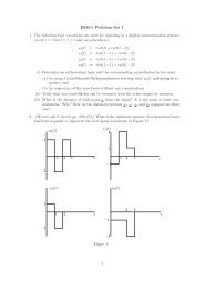
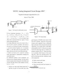
Introduction 5Table 3Main parameters of WLAN communication systemsParameter Bluetooth IEEE 802.11b IEEE 802.11a/g/h IEEE 802.11n<strong>Carrier</strong> frequency2.4 GHz(ISM)2.4 GHz (ISM) 2.4 GHz/5 GHz(ISM)2.4 GHz/5 GHz(ISM)Peak data rate 2 Mbit/s 5.5 Mbit/s 54 Mbit/s 248 Mbit/s<strong>Multi</strong>ple accessTDMA <strong>and</strong>FH-CDMADS-CDMA <strong>OFDM</strong>-TDMA <strong>OFDM</strong>-TDMAServices Data Data High rate data High rate dataPower densityTimeFrequencyFigure 1Principle of FDMA (with N c = 5 sub-channels)FDMA is a multiple access technology widely used in satellite, cable, <strong>and</strong> terrestrialradio networks. FDMA subdivides the total b<strong>and</strong>width into N c narrowb<strong>and</strong> sub-channelsthat are available during the whole transmission time (see Figure 1). This requires b<strong>and</strong>passfilters with sufficient stop b<strong>and</strong> attenuation. Furthermore, a sufficient guard b<strong>and</strong> isleft between two adjacent spectra in order to cope with frequency deviations of localoscillators <strong>and</strong> to minimize interference from adjacent channels. The main advantagesof FDMA are in its low required transmit power <strong>and</strong> in channel equalization that iseither not needed or much simpler than with other multiple access techniques. However,its drawback in a cellular system might be the implementation of N c modulators <strong>and</strong>demodulators at the base station (BS).TDMA is a popular multiple access technique, which is used in several internationalst<strong>and</strong>ards. In a TDMA system all users employ the same b<strong>and</strong> <strong>and</strong> are separated by allocatingshort <strong>and</strong> distinct time slots, one or several assigned to a user (see Figure 2). InTDMA, neglecting the overhead due to framing <strong>and</strong> burst formatting, the multiplexedsignal b<strong>and</strong>width will be approximately N c times higher than in an FDMA system, henceleading to quite complex equalization, especially for high data rate applications. Thechannel separation of TDMA <strong>and</strong> FDMA is based on the orthogonality of signals. Therefore,in a cellular system, the co-channel interference is only present from the re-use offrequency.On the contrary, in CDMA systems all users transmit at the same time on the samecarrier using a wider b<strong>and</strong>width than in a TDMA system (see Figure 3). The signals ofusers are distinguished by assigning different spreading codes with low cross-correlation
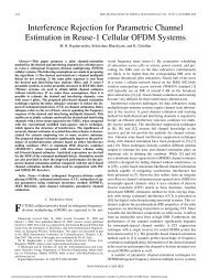
6 IntroductionPower densityTimeFrequencyFigure 2Principle of TDMA (with five time slots)Power densityTimeFrequencyFigure 3Principle of CDMA (with five spreading codes)properties. Advantages of the spread spectrum technique are immunity against multi-pathdistortion, simple frequency planning, high flexibility, variable rate transmission, <strong>and</strong>resistance to interference.In Table 4, the main advantages <strong>and</strong> drawbacks of FDMA, TDMA, <strong>and</strong> CDMA aresummarized.<strong>From</strong> 3G to 4G <strong>Multi</strong>ple Access SchemesBesides offering new services <strong>and</strong> applications, the success of the next generation ofwireless systems (4G) will strongly depend on the choice of the concept <strong>and</strong> technologyinnovations in architecture, spectrum allocation, spectrum utilization, <strong>and</strong> exploitation [40,41]. Therefore, new high performance physical layer <strong>and</strong> multiple access technologiesare needed to provide high speed data rates with flexible b<strong>and</strong>width allocation. A lowcost generic radio interface, being operational in various mixed-cell environments withscalable b<strong>and</strong>width <strong>and</strong> data rates, is needed to fulfill these requirements.The technique of spread spectrum allows the above requirements to be at least partiallyfulfilled. As explained earlier, a multiple access scheme based on direct sequence codedivision multiple access (DS-CDMA) relies on spreading the data stream using an assignedspreading code for each user in the time domain [42, 47, 49, 50]. The capability of minimizingmultiple access interference is given by the cross-correlation properties of thespreading codes. In the case of severe multi-path propagation in mobile communications,the capability of distinguishing one component from others in the composite received
Introduction 7Table 4Advantages <strong>and</strong> drawbacks of different multiple access schemes<strong>Multi</strong>ple access scheme Advantages DrawbacksFDMA – Low transmit power– Robust to multi-path– Easy frequency planning– Low delay– Low peak data rate– Loss due to guard b<strong>and</strong>s– Sensitive to narrowb<strong>and</strong>interferenceTDMA – High peak data rate– High multiplexing gain inthe case of bursty traffic– High transmit power– Sensitive to multi-path– Difficult frequency planningCDMA – Low transmit power– Robust to multi-path– Easy frequency planning– High scalability– Low delay– Low peak data rate– Limited capacity per sectordue to multiple access interferencesignal is offered by the auto-correlation properties of the spreading codes [47]. Theso-called rake receiver should contain multiple correlators, each matched to a differentresolvable path in the received composite signal [42]. The performance of a DS-CDMAsystem will strongly depend on the number of active users, the channel characteristics,<strong>and</strong> the number of arms employed in the rake. The system capacity is limited by selfinterference<strong>and</strong> multiple access interference, which results from the imperfect auto- <strong>and</strong>cross-correlation properties of spreading codes. Therefore, it will be difficult for a DS-CDMA receiver to make full use of the received signal energy scattered in the timedomain <strong>and</strong> hence to h<strong>and</strong>le full load conditions [42].The technique of multi-carrier transmission has received wide interest, especially forhigh data rate broadcast applications. The history of orthogonal multi-carrier transmissiondates back to the mid-1960s, when Chang published his papers on the synthesis of b<strong>and</strong>limitedsignals for multi-channel transmission [8, 9]. He introduced the basic principleof transmitting data simultaneously through a b<strong>and</strong>-limited channel without interferencebetween sub-channels (without inter-channel interference, ICI) <strong>and</strong> without interferencebetween consecutive transmitted symbols (without inter-symbol interference, ISI)inthetime domain. Later, Saltzberg performed further analyses [43]. A major contribution tomulti-carrier transmission was presented in 1971 by Weinstein <strong>and</strong> Ebert [51] who usedthe Fourier transform for baseb<strong>and</strong> processing instead of a bank of sub-carrier oscillators.To combat ICI <strong>and</strong> ISI, they introduced the well-known guard time between the transmittedsymbols with raised cosine windowing.The main advantages of multi-carrier transmission are its robustness in frequencyselective fading channels <strong>and</strong>, in particular, the reduced signal processing complexityby equalization in the frequency domain.The basic principle of multi-carrier modulation relies on the transmission of data bydividing a high-rate data stream into several low rate sub-streams. These sub-streams aremodulated on different sub-carriers [4, 7, 12]. By using a large number of sub-carriers,
8 Introductiona high immunity against multi-path dispersion can be provided since the useful symbolduration T s on each sub-stream is much larger than the channel time dispersion.Hence, the effects of ISI are minimized. Since the amount of filters <strong>and</strong> oscillatorsnecessary is considerable for a large number of sub-carriers, an efficient digital implementationof a special form of multi-carrier modulation, called orthogonal frequency divisionmultiplexing (<strong>OFDM</strong>), with rectangular pulse-shaping <strong>and</strong> guard time was proposed inReference [4]. <strong>OFDM</strong> can be easily realized by using the discrete Fourier transform(DFT). <strong>OFDM</strong>, having densely spaced sub-carriers with overlapping spectra of the modulatedsignals, ab<strong>and</strong>ons the use of steep b<strong>and</strong>-pass filters to detect each sub-carrier as itis used in FDMA schemes. Therefore, it offers high spectral efficiency.Today, progress in digital technology has enabled the realization of a DFT also forlarge numbers of sub-carriers (up to several thous<strong>and</strong>), through which <strong>OFDM</strong> has gainedmuch importance. The breakthrough of <strong>OFDM</strong> came in the 1990s as it was the modulationchosen for ADSL in the USA [11] <strong>and</strong> was selected for the European DABst<strong>and</strong>ard [14]. This success continued with the choice of <strong>OFDM</strong> for the European DVB-T st<strong>and</strong>ard [17] in 1995 <strong>and</strong> later for the WLAN st<strong>and</strong>ard IEEE 802.11a [32] <strong>and</strong> theinteractive terrestrial return channel (DVB-RCT) [16] as well as the European DVB-Hst<strong>and</strong>ard [15]. Further deployments of <strong>OFDM</strong> technology are in the cellular mobile radiost<strong>and</strong>ard 3GPP LTE <strong>and</strong> future broadb<strong>and</strong> wireless access st<strong>and</strong>ards such as HIPERMAN<strong>and</strong> IEEE 802.16x/WiMAX [19, 33, 52, 53]. Table 5 summarizes the main characteristicsof several broadcasting <strong>and</strong> WLAN st<strong>and</strong>ards employing <strong>OFDM</strong>.The advantages of multi-carrier modulation on the one h<strong>and</strong> <strong>and</strong> the flexibility offeredby the spread spectrum technique on the other h<strong>and</strong> have motivated many researchers toinvestigate the combination of both techniques, known as <strong>Multi</strong>-<strong>Carrier</strong> <strong>Spread</strong> <strong>Spectrum</strong>(<strong>MC</strong>-SS). This combination, published in 1993 by several authors independently [10, 13,20, 27, 37, 48, 56], has introduced new multiple access schemes called <strong>MC</strong>-CDMA <strong>and</strong><strong>MC</strong>-DS-CDMA. It allows one to benefit from several advantages of both multi-carriermodulation <strong>and</strong> spread spectrum systems by offering, for instance, high flexibility, highspectral efficiency, simple <strong>and</strong> robust detection techniques, <strong>and</strong> narrowb<strong>and</strong> interferencerejection capability.<strong>Multi</strong>-carrier modulation <strong>and</strong> multi-carrier spread spectrum are today considered potentialc<strong>and</strong>idates to fulfill the requirements of next-generation (4G) high speed wirelessmultimedia communications systems, where spectral efficiency <strong>and</strong> flexibility are consideredas the most important criteria for the choice of the air interface.Table 5Examples of wireless transmission systems employing <strong>OFDM</strong>Parameter DAB DVB-T IEEE 802.11a IEEE 802.11n<strong>Carrier</strong>frequencyVHF VHF <strong>and</strong> UHF 2.4 <strong>and</strong> 5 GHz 2.4 <strong>and</strong> 5 GHzB<strong>and</strong>width 1.5 MHz 8MHz (7MHz) 20 MHz 40 MHzMax. data rate 1.7 Mbit/s 31.7 Mbit/s 54 Mbit/s 248 Mbit/sNumber of 192 up to 1536 1705 <strong>and</strong> 6817 52 52 <strong>and</strong> 104sub-carriers (256 up to 2048) (2048 <strong>and</strong> 8196) (64) (64 <strong>and</strong> 128)(FFT size)
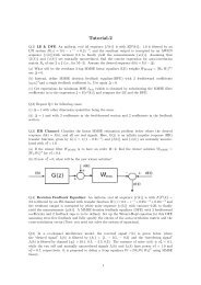
Introduction 9<strong>Multi</strong>-<strong>Carrier</strong> <strong>Spread</strong> <strong>Spectrum</strong>Since 1993, various combinations of multi-carrier modulation with the spread spectrumtechnique have been introduced as multiple access schemes. It has been shown thatmulti-carrier spread spectrum (<strong>MC</strong>-SS) offers high spectral efficiency, robustness, <strong>and</strong>flexibility [31]. Two different philosophies exist, namely <strong>MC</strong>-CDMA (or <strong>OFDM</strong>-CDMA)<strong>and</strong> <strong>MC</strong>-DS-CDMA (see Figure 4 <strong>and</strong> Table 6).<strong>MC</strong>-CDMA is based on a serial concatenation of direct sequence (DS) spreadingwith multi-carrier modulation [10, 20, 27, 56]. The high-rate DS spread data stream ofspreading code01L-1subcarrier f 0subcarrier f 1subcarrier f Nc −1<strong>MC</strong>-CDMA(Frequency diversity)spread data symbols01L-1data symbolsserialtoparallelconverterspreading code0 1L-1subcarrier f 0subcarrier f 1subcarrier f Nc −1spread data symbols<strong>MC</strong>-DS-CDMA(Time diversity)0 1L-1Figure 4General principle of <strong>MC</strong>-CDMA <strong>and</strong> <strong>MC</strong>-DS-CDMA systemsTable 6Main characteristics of different <strong>MC</strong>-SS conceptsParameter <strong>MC</strong>-CDMA <strong>MC</strong>-DS-CDMA<strong>Spread</strong>ing Frequency direction Time directionSub-carrier spacing F S = P GF S ≥ P GN c T d N c T dDetection algorithmSpecific characteristicsApplicationsMRC, EGC, ZF, MMSEequalization, IC, MLDVery efficient for thesynchronous downlink by usingorthogonal codesSynchronous uplink <strong>and</strong>downlinkCorrelation detector (coherentrake)Designed especially for anasynchronous uplinkAsynchronous uplink <strong>and</strong>downlink
10 Introductionprocessing gain P G is multi-carrier modulated in the way that the chips of a spreaddata symbol are transmitted in parallel <strong>and</strong> the assigned data symbol is simultaneouslytransmitted on each sub-carrier (see Figure 4). As for DS-CDMA, a user may occupythe total b<strong>and</strong>width for the transmission of a single data symbol. Separation of the usersignals is performed in the code domain. Each data symbol is copied on the sub-streamsbefore multiplying it with a chip of the spreading code assigned to the specific user. Thisshows that an <strong>MC</strong>-CDMA system performs the spreading in the frequency direction <strong>and</strong>,thus, has an additional degree of freedom compared to a DS-CDMA system. Mappingof the chips in the frequency direction allows for simple methods of signal detection.This concept was proposed with <strong>OFDM</strong> for optimum use of the available b<strong>and</strong>width.The realization of this concept implies a guard time between adjacent <strong>OFDM</strong> symbolsto prevent ISI or to assume that the symbol duration is significantly larger than the timedispersion of the channel. The number of sub-carriers N c has to be chosen sufficientlylarge to guarantee frequency nonselective fading on each sub-channel. The applicationof orthogonal codes, such as Walsh–Hadamard codes for a synchronous system, e.g. thedownlink of a cellular system, guarantees the absence of multiple access interference inan ideal channel <strong>and</strong> a minimum multiple access interference in a fading channel. For signaldetection, single-user detection techniques such as maximum ratio combining (MRC),equal gain combining (EGC), zero forcing (ZF), or minimum mean square error (MMSE)equalization, as well as multi-user detection techniques like interference cancellation (IC)or maximum likelihood detection (MLD), can be applied.As depicted in Figure 4, <strong>MC</strong>-DS-CDMA modulates sub-streams on sub-carriers with acarrier spacing proportional to the inverse of the chip rate. This will guarantee orthogonalitybetween the spectra of the sub-streams [44]. If the spreading code length is smalleror equal to the number of sub-carriers N c , a single data symbol is not spread in the frequencydirection, instead it is spread in the time direction. <strong>Spread</strong> spectrum is obtained bymodulating N c time spread data symbols on parallel sub-carriers. By using high numbersof sub-carriers, this concept benefits from time diversity. However, due to the frequencynonselective fading per sub-channel, frequency diversity can only be exploited if channelcoding with interleaving or sub-carrier hopping is employed, or if the same informationis transmitted on several sub-carriers in parallel. Furthermore, higher frequency diversitycould be achieved if the sub-carrier spacing is chosen larger than the chip rate. Thisconcept was investigated for an asynchronous uplink scenario. For data detection, N ccoherent receivers can be used.It can be noted that both schemes have a generic architecture. In the case where thenumber of sub-carriers N c = 1, the classical DS-CDMA transmission scheme is obtained,whereas without spreading (P G = 1) it results in a pure <strong>OFDM</strong> system.By using a variable spreading factor in frequency <strong>and</strong>/or time <strong>and</strong> a variable sub-carrierallocation, the system can easily be adapted to different environments such as multi-cell<strong>and</strong> single-cell topologies, each with different coverage areas.Today, in parallel with multi-carrier transmission, the field of multi-carrier spread spectrumcommunications is considered to be an independent <strong>and</strong> important research topic(see References [21] to [25], [28], <strong>and</strong> [38]). Several deep system analysis <strong>and</strong> comparisonsof <strong>MC</strong>-CDMA <strong>and</strong> <strong>MC</strong>-DS-CDMA with DS-CDMA have been performed thatshow the superiority of <strong>MC</strong>-SS [26, 31, 34–36]. In addition, new application fields havebeen proposed such as high rate cellular mobile (4G), high rate wireless indoor, <strong>and</strong> fixed
Introduction 11<strong>and</strong> broadb<strong>and</strong> wireless access (F/BWA). In addition to system-level analysis, a multitudeof research activities have been addressed to develop appropriate strategies for detection,interference cancellation, channel coding, modulation, synchronization (especially uplink),<strong>and</strong> low cost implementation design.The Aim of This BookThe interest in multi-carrier transmission <strong>and</strong> in multi-carrier spread spectrum is stillgrowing. Many researchers <strong>and</strong> system designers are involved in system aspects <strong>and</strong> theimplementation of these new techniques. However, a comprehensive collection of theirwork is still missing.The aim of this book is first to describe <strong>and</strong> analyze the basic concepts of multi-carriertransmission <strong>and</strong> its combination with spread spectrum, where the different architectures<strong>and</strong> the different detection strategies are detailed. Concrete examples of its applicationsfor future cellular mobile communications systems are given. Then, we examine otherderivatives of <strong>MC</strong>-SS (e.g. <strong>OFDM</strong>A, SS-<strong>MC</strong>-MA, <strong>and</strong> DFT-spread <strong>OFDM</strong>/interleavedFDMA) <strong>and</strong> other variants of the combination of <strong>OFDM</strong> with TDMA, which are todaypart of LTE, WiMAX, WLAN, <strong>and</strong> DVB-RCT systems. Basic <strong>OFDM</strong> implementationissues, valid for most of these combinations, such as channel coding, modulation, digitalI/Q generation, synchronization, channel estimation, <strong>and</strong> effects of phase noise <strong>and</strong>nonlinearity are further analyzed.Chapter 1 covers the fundamentals of today’s wireless communications. First a detailedanalysis of the radio channel (outdoor <strong>and</strong> indoor) <strong>and</strong> its modeling are presented. Thenthe principle of <strong>OFDM</strong> multi-carrier transmission is introduced. In addition, a generaloverview of the spread spectrum technique, especially of DS-CDMA, is given. Examplesof applications of <strong>OFDM</strong> <strong>and</strong> DS-CDMA for broadcast, WLAN, <strong>and</strong> cellular systems(IS-95, CDMA-2000, WCDMA/UMTS, HSPA) are briefly presented.Chapter 2 describes the combinations of multi-carrier transmission with the spread spectrumtechnique, namely <strong>MC</strong>-CDMA <strong>and</strong> <strong>MC</strong>-DS-CDMA. It includes a detailed descriptionof the different detection strategies (single-user <strong>and</strong> multi-user) <strong>and</strong> presents their performancein terms of the bit error rate (BER), spectral efficiency, <strong>and</strong> complexity. Here acellular system with a point to multi-point topology is considered. Both downlink <strong>and</strong>uplink architectures are examined.Hybrid multiple access schemes based on <strong>OFDM</strong>, <strong>MC</strong>-SS, or spread spectrum areanalyzed in Chapter 3. This chapter covers <strong>OFDM</strong>A, being a derivative of <strong>MC</strong>-CDMA,<strong>OFDM</strong>-TDMA, SS-<strong>MC</strong>-MA, DFT-spread <strong>OFDM</strong>/interleaved FDMA, <strong>and</strong> ultra wideb<strong>and</strong>(UWB) schemes. All these multiple access schemes have recently received wide interest.Their concrete application fields are detailed in Chapter 5.The issues of digital implementation of multi-carrier transmission systems, essentialespecially for system <strong>and</strong> hardware designers, are addressed in Chapter 4. Here, thedifferent functions such as digital I/Q generation, analogue/digital conversion, digitalmulti-carrier modulation/demodulation, synchronization (time, frequency), channel estimation,coding/decoding, <strong>and</strong> other related RF issues such as nonlinearities, phase noise,<strong>and</strong> narrowb<strong>and</strong> interference rejection are analyzed.In Chapter 5, concrete application fields of <strong>OFDM</strong>A, <strong>OFDM</strong>-TDMA, <strong>and</strong> <strong>MC</strong>-SS forB3G cellular mobile (LTE <strong>and</strong> WiMAX), 4G (IMT-Advanced), wireless indoor (WLAN),
12 Introduction<strong>and</strong> interactive multimedia communication (DVB-T return channel) are outlined, wherefor each of these systems the multi-carrier architecture <strong>and</strong> their main parameters aredescribed. The capacity advantages of using adaptive channel coding <strong>and</strong> modulation,adaptive spreading, <strong>and</strong> scalable b<strong>and</strong>width allocation are discussed.Finally, Chapter 6 covers further techniques that can be used to enhance system capacityor offer more flexibility for the implementation <strong>and</strong> deployment of the transmissionsystems examined in Chapter 5. Here, diversity techniques such as space–time/frequencycoding <strong>and</strong> Tx/Rx antenna diversity in MIMO concepts <strong>and</strong> the software-defined radio(SDR) are introduced.References[1] 3GPP (TS 25.401), “UTRAN overall description,” Technical Specification, Sophia Antipolis, France,2002.[2] 3GPP (TS 25.308), “High speed downlink packet access (HSDPA): overall description; Stage 2,” TechnicalSpecification, Sophia Antipolis, France, 2004.[3] 3GPP (TS 25.309), “FDD enhanced uplink: overall description; Stage 2,” Technical Specification, SophiaAntipolis, France, 2006.[4] Alard M. <strong>and</strong> Lassalle R., “Principles of modulation <strong>and</strong> channel coding for digital broadcasting formobile receivers,” European Broadcast Union Review, no. 224, pp. 47–69, Aug. 1987.[5] Bhargava V. K., Haccoun D., Matyas R., <strong>and</strong> Nuspl P. P., Digital Communications by Satellite, NewYork: John Wiley & Sons, Inc., 1981.[6] Bi Q., Zysman G. I., <strong>and</strong> Menkes H, “Wireless mobile communications at the start of the 21st century,”IEEE Communications Magazine, vol. 39, pp. 110–116, Jan. 2001.[7] Bingham J. A. C., “<strong>Multi</strong>carrier modulation for data transmission: an idea whose time has come,” IEEECommunications Magazine, vol. 28, pp. 5–14, May 1990.[8] Chang R. W., “Synthesis of b<strong>and</strong>-limited orthogonal signals for multi-channel data transmission,” BellLabs Technical Journal, no. 45, pp. 1775–1796, Dec. 1966.[9] Chang R. W. <strong>and</strong> Gibby R. A., “A theoretical study of performance of an orthogonal multiplexing datatransmission scheme,” IEEE Transactions on Communication Technology, vol. 16, pp. 529–540, Aug.1968.[10] Chouly A., Brajal A., <strong>and</strong> Jourdan S., “Orthogonal multicarrier techniques applied to direct sequencespread spectrum CDMA systems,” in Proc. IEEE Global Telecommunications Conference (GLOBECOM’93), Houston, USA, pp. 1723–1728, Nov./Dec. 1993.[11] Chow J. S., Tu J.-C., <strong>and</strong> Cioffi J. M., “A discrete multitone transceiver system for HDSL applications,”IEEE Journal on Selected Areas in Communications (JSAC), vol. 9, pp. 895–908, Aug. 1991.[12] Cimini L. J., “Analysis <strong>and</strong> simulation of a digital mobile channel using orthogonal frequency divisionmultiplexing,” IEEE Transactions on Communications, vol. 33, pp. 665–675, July 1985.[13] DaSilva V. <strong>and</strong> Sousa E. S., “Performance of orthogonal CDMA codes for quasi-synchronous communicationsystems,” in Proc. IEEE International Conference on Universal Personal Communications (ICUPC’93), Ottawa, Canada, pp. 995–999, Oct. 1993.[14] ETSI DAB (EN 300 401), “Radio broadcasting systems; digital audio broadcasting (DAB) to mobile,portable <strong>and</strong> fixed receivers,” Sophia Antipolis, France, April 2000.[15] ETSI DVB-H (EN 302 304), “Digital video broadcasting (DVB); transmission system for h<strong>and</strong>heldterminals (DVB-H),” Sophia Antipolis, France, Nov. 2004.[16] ETSI DVB RCT (EN 301 958), “Interaction channel for digital terrestrial television (RCT) incorporatingmultiple access <strong>OFDM</strong>,” Sophia Antipolis, France, March 2001.[17] ETSI DVB-T (EN 300 744), “Digital video broadcasting (DVB); framing structure, channel coding <strong>and</strong>modulation for digital terrestrial television,” Sophia Antipolis, France, July 1999.[18] ETSI GSM Recommendations, 05 series, Sophia Antipolis, France, Sept. 1994.[19] ETSI HIPERMAN (TR 101 856), “High performance metropolitan area network, requirements MAC <strong>and</strong>physical layer below 11 GHz b<strong>and</strong>,” Sophia Antipolis, France, 2004.
References 13[20] Fazel K., “Performance of CDMA/<strong>OFDM</strong> for mobile communications system,” in Proc. IEEE InternationalConference on Universal Personal Communications (ICUPC ’93), Ottawa, Canada, pp. 975–979,Oct. 93.[21] Fazel K. <strong>and</strong> Fettweis G. (eds), <strong>Multi</strong>-<strong>Carrier</strong> <strong>Spread</strong> <strong>Spectrum</strong>, Boston: Kluwer Academic Publishers,1997; also in Proceedings of the 1st International Workshop on <strong>Multi</strong>-<strong>Carrier</strong> <strong>Spread</strong> <strong>Spectrum</strong> (<strong>MC</strong>-SS’97).[22] Fazel K. <strong>and</strong> Kaiser S. (eds), <strong>Multi</strong>-<strong>Carrier</strong> <strong>Spread</strong> <strong>Spectrum</strong> <strong>and</strong> Related Topics, Boston: Kluwer AcademicPublishers, 2000–2004; also in Proceedings of the International Workshop on <strong>Multi</strong>-<strong>Carrier</strong> <strong>Spread</strong><strong>Spectrum</strong> <strong>and</strong> Related Topics (<strong>MC</strong>-SS ’1999–2003).[23] Fazel K. <strong>and</strong> Kaiser S. (eds), <strong>Multi</strong>-<strong>Carrier</strong> <strong>Spread</strong> <strong>Spectrum</strong> <strong>and</strong> Related Topics, Dordrecht: Springer,2006; also in Proceedings of the International Workshop on <strong>Multi</strong>-<strong>Carrier</strong> <strong>Spread</strong> <strong>Spectrum</strong> <strong>and</strong> RelatedTopics (<strong>MC</strong>-SS 2005).[24] Fazel K. <strong>and</strong> Kaiser S. (eds), Special Issue on <strong>Multi</strong>-<strong>Carrier</strong> <strong>Spread</strong> <strong>Spectrum</strong> <strong>and</strong> Related Topics, EuropeanTransactions on Telecommunications (ETT), 2000–2006.[25] Fazel K. <strong>and</strong> Kaiser S. (eds), Special Issue on <strong>Multi</strong>-<strong>Carrier</strong> <strong>Spread</strong> <strong>Spectrum</strong> <strong>and</strong> Related Topics, EuropeanTransactions on Telecommunications (ETT), vol. 19, no. 5, 2008.[26] Fazel K., Kaiser S., <strong>and</strong> Schnell M., “A flexible <strong>and</strong> high performance cellular mobile communicationssystem based on orthogonal multi-carrier SSMA,” Wireless Personal Communications, vol. 2, nos. 1 <strong>and</strong>2, pp. 121–144, 1995.[27] Fazel K. <strong>and</strong> Papke L., “On the performance of convolutionally-coded CDMA/<strong>OFDM</strong> for mobilecommunications system,” in Proc. IEEE International Symposium on Personal, Indoor <strong>and</strong> Mobile RadioCommunications (PIMRC ’93), Yokohama, Japan, pp. 468–472, Sept. 1993.[28] Fazel K. <strong>and</strong> Prasad R. (eds), Special Issue on <strong>Multi</strong>-<strong>Carrier</strong> <strong>Spread</strong> <strong>Spectrum</strong>, European Transactionson Telecommunications (ETT), vol. 10, no. 4, July/Aug. 1999.[29] Goodman D. J., “Second generation wireless information network,” IEEE Transactions on VehicularTechnology, vol. 40, no. 2, pp. 366–374, May 1991.[30] Goodman D. J., “Trends in cellular <strong>and</strong> cordless communications,” IEEE Communications Magazine,vol. 29, pp. 31–40, June 1991.[31] Hara S. <strong>and</strong> Prasad R., “Overview of multicarrier CDMA,” IEEE Communications Magazine, vol. 35,pp. 126–133, Dec. 1997.[32] IEEE 802.11 (P802.11a/D6.0), “LAN/MAN specific requirements – Part 2: wireless MAC <strong>and</strong> PHYspecifications – high speed physical layer in the 5 GHz b<strong>and</strong>,” IEEE 802.11, May 1999.[33] IEEE 802.16d, “Air interface for fixed broadb<strong>and</strong> wireless access systems,” IEEE 802.16, May 2004.[34] Kaiser S., “<strong>OFDM</strong>-CDMA versus DS-CDMA: performance evaluation for fading channels,” in Proc.IEEE International Conference on Communications (ICC ’95), Seattle, USA, pp. 1722–1726, June1995.[35] Kaiser S., “On the performance of different detection techniques for <strong>OFDM</strong>-CDMA in fading channels,”in Proc. IEEE Global Telecommunications Conference (GLOBECOM ’95), Singapore, pp. 2059–2063,Nov. 1995.[36] Kaiser S., <strong>Multi</strong>-<strong>Carrier</strong> CDMA Mobile Radio <strong>Systems</strong> – Analysis <strong>and</strong> Optimization of Detection,Decoding, <strong>and</strong> Channel Estimation, Düsseldorf: VDI-Verlag, Fortschrittberichte VDI, series 10, no. 531,1998, PhD thesis.[37] Kondo S. <strong>and</strong> Milstein L. B., “On the use of multicarrier direct sequence spread spectrum systems,” inProc. IEEE Military Communications Conference (MILCOM ’93), Boston, USA, pp. 52–56, Oct. 1993.[38] Linnartz J. P. <strong>and</strong> Hara S. (eds), Special Issue on <strong>Multi</strong>-<strong>Carrier</strong> Communications, Wireless PersonalCommunications, Kluwer Academic Publishers, vol. 2, nos. 1 <strong>and</strong> 2, 1995.[39] Mouly M. <strong>and</strong> Paulet M.-B., The GSM System for Mobile Communications, Palaiseau, Published byauthors, France, 1992.[40] Pereira J. M., “Beyond third generation,” in Proc. International Symposium on Wireless Personal<strong>Multi</strong>media Communications (WP<strong>MC</strong> ’99), Amsterdam, The Netherl<strong>and</strong>s, Sept. 1999.[41] Pereira J. M., “Fourth generation: now it is personal!,” in Proc. IEEE International Symposium onPersonal, Indoor <strong>and</strong> Mobile Radio Communications (PIMRC 2000), London, UK, pp. 1009–1016, Sept.2000.[42] Pickholtz R. L., Schilling D. L., <strong>and</strong> Milstein L. B., “Theory of spread spectrum communications – atutorial,” IEEE Transactions on Communication Technology, vol. 30, pp. 855–884, May 1982.
14 Introduction[43] Saltzberg, B. R., “Performance of an efficient parallel data transmission system,” IEEE Transactions onCommunication Technology, vol. 15, pp. 805–811, Dec. 1967.[44] Sourour E. A. <strong>and</strong> Nakagawa M., “Performance of orthogonal multi-carrier CDMA in a multipath fadingchannel,” IEEE Transactions on Communications, vol. 44, pp. 356–367, March 1996.[45] TIA/EIA/IS-95, “Mobile station-base station compatibility st<strong>and</strong>ard for dual mode wideb<strong>and</strong> spreadspectrum cellular system,” July 1993.[46] TIA/EIA/IS-CDMA-2000, “Physical layer st<strong>and</strong>ard for CDMA-2000 spread spectrum systems,” Aug.1999.[47] Turin G. L., “Introduction to spread spectrum anti-multi-path techniques <strong>and</strong> their application to urb<strong>and</strong>igital radio,” Proceedings of the IEEE, vol. 68, pp. 328–353, March 1980.[48] V<strong>and</strong>endorpe L., “<strong>Multi</strong>tone direct sequence CDMA system in an indoor wireless environment,” inProc. IEEE First Symposium of Communications <strong>and</strong> Vehicular Technology, Delft, The Netherl<strong>and</strong>s,pp. 4.1.1–4.1.8, Oct. 1993.[49] Viterbi A. J., “<strong>Spread</strong> spectrum communications – myths <strong>and</strong> realities,” IEEE Communications Magazine,vol. 17, pp. 11–18, May 1979.[50] Viterbi A. J., CDMA: Principles of <strong>Spread</strong> <strong>Spectrum</strong> Communication, Reading: Addison-Wesley, 1995.[51] Weinstein S. B. <strong>and</strong> Ebert P. M., “Data transmission by frequency-division multiplexing using the discreteFourier transform,” IEEE Transactions on Communication Technology, vol. 19, pp. 628–634, Oct. 1971.[52] WiMAX Forum, “Mobile WiMAX – Part I: a technical overview <strong>and</strong> performance evaluation,” WhitePaper, Aug. 2006.[53] WiMAX Forum, www.wimaxforum.org.[54] WINNER Project, “WINNER II system concept description,” Deliverable D6.13.14, Nov. 2007.[55] WINNER Project, www.ist-winner.org.[56] Yee N., Linnartz J.-P., <strong>and</strong> Fettweis G., “<strong>Multi</strong>-carrier CDMA for indoor wireless radio networks,” inProc. International Symposium on Personal, Indoor <strong>and</strong> Mobile Radio Communications (PIMRC ’93),Yokohama, Japan, pp. 109–113, Sept. 1993.
1FundamentalsThis chapter describes the fundamentals of today’s wireless communications. First adetailed description of the radio channel <strong>and</strong> its modeling is presented, followed by theintroduction of the principle of <strong>OFDM</strong> multi-carrier transmission. In addition, a generaloverview of the spread spectrum technique, especially DS-CDMA, is given <strong>and</strong> examplesof potential applications for <strong>OFDM</strong> <strong>and</strong> DS-CDMA are analyzed. This introduction isessential for a better underst<strong>and</strong>ing of the idea behind the combination of <strong>OFDM</strong> withthe spread spectrum technique, which is briefly introduced in the last part of this chapter.1.1 Radio Channel CharacteristicsUnderst<strong>and</strong>ing the characteristics of the communications medium is crucial for the appropriateselection of transmission system architecture, dimensioning of its components, <strong>and</strong>optimizing system parameters. Especially mobile radio channels are considered to be themost difficult channels, since they suffer from many imperfections like multi-path fading,interference, Doppler shift, <strong>and</strong> shadowing. The choice of system components is totallydifferent if, for instance, multi-path propagation with long echoes dominates the radiopropagation.Therefore, an accurate channel model describing the behavior of radio wave propagationin different environments such as mobile/fixed <strong>and</strong> indoor/outdoor is needed. This mayallow one, through simulations, to estimate <strong>and</strong> validate the performance of a giventransmission scheme in its several design phases.1.1.1 Underst<strong>and</strong>ing Radio ChannelsIn mobile radio channels (see Figure 1-1), the transmitted signal suffers from differenteffects, which are characterized as follows.<strong>Multi</strong>-path propagation occurs as a consequence of reflections, scattering, <strong>and</strong> diffractionof the transmitted electromagnetic wave at natural <strong>and</strong> man-made objects. Thus, atthe receiver antenna, a multitude of waves arrives from many different directions withdifferent delays, attenuations, <strong>and</strong> phases. The superposition of these waves results inamplitude <strong>and</strong> phase variations of the composite received signal.<strong>Multi</strong>-<strong>Carrier</strong> <strong>and</strong> <strong>Spread</strong> <strong>Spectrum</strong> <strong>Systems</strong> Second Edition K. Fazel <strong>and</strong> S. Kaiser© 2008 John Wiley & Sons, Ltd
16 FundamentalsBSTSFigure 1-1Time-variant multi-path propagationDoppler spread is caused by moving objects in the mobile radio channel. Changes in thephases <strong>and</strong> amplitudes of the arriving waves lead to time-variant multi-path propagation.Even small movements on the order of the wavelength may result in a totally differentwave superposition. The varying signal strength due to time-variant multi-path propagationis referred to as fast fading.Shadowing is caused by obstruction of the transmitted waves by, for example, hills,buildings, walls, <strong>and</strong> trees, which results in more or less strong attenuation of the signalstrength. Compared to fast fading, longer distances have to be covered to change theshadowing constellation significantly. The varying signal strength due to shadowing iscalled slow fading <strong>and</strong> can be described by a log-normal distribution [41].Path loss indicates how the mean signal power decays with distance between thetransmitter <strong>and</strong> receiver. In free space, the mean signal power decreases with the squareof the distance between the base station (BS) <strong>and</strong> terminal station (TS). In a mobile radiochannel, where often no line of sight (NLOS) exists, signal power decreases with a powerhigher than two <strong>and</strong> is typically in the order of three to five.Variations of the received power due to shadowing <strong>and</strong> path loss can be efficientlycounteracted by power control. In the following, the mobile radio channel is describedwith respect to its fast fading characteristic.1.1.2 Channel ModelingThe mobile radio channel can be characterized by the time-variant channel impulseresponse h(τ, t) or by the time-variant channel transfer function H (f , t), which is theFourier transform of h(τ, t). The channel impulse response represents the response ofthe channel at time t due to an impulse applied at time t − τ. The mobile radio channelis assumed to be a wide-sense stationary r<strong>and</strong>om process, i.e. the channel has a fadingstatistic that remains constant over short periods of time or small spatial distances. Inenvironments with multi-path propagation, the channel impulse response is composed of
Radio Channel Characteristics 17a large number of scattered impulses received over N p different paths:h(τ, t) =N p −1∑p=0a p e j(2πf D,pt+ϕ p ) δ(τ − τ p ), (1.1)where{1δ(τ − τ p ) =0if τ = τ potherwise(1.2)<strong>and</strong> a p , f D,p , ϕ p ,<strong>and</strong>τ p are the amplitude, Doppler frequency, phase, <strong>and</strong> propagationdelay, respectively associated with path p, p = 0,...,N p − 1. The assigned channeltransfer function isH(f,t) =N p −1∑p=0a p e j(2π(f D,pt−fτ p )+ϕ p ) . (1.3)The delays are measured relative to the first detectable path at the receiver. The Dopplerfrequencyf D,p = vf c cos(α p )(1.4)cdepends on the velocity v of the terminal station, the speed of light c, the carrier frequencyf c , <strong>and</strong> the angle of incidence α p of a wave assigned to path p. A channel impulse responsewith a corresponding channel transfer function is illustrated in Figure 1-2.The delay power density spectrum ρ(τ) that characterizes the frequency selectivity ofthe mobile radio channel gives the average power of the channel output as a function ofthe delay τ. The mean delay τ, the root mean square (RMS) delay spread τ RMS ,<strong>and</strong>themaximum delay τ max are characteristic parameters of the delay power density spectrum.The mean delay isτ =N p −1∑p=0N p −1∑p=0τ p p p, (1.5)h(t, t)H(f, t)t maxtBfFigure 1-2 Time-variant channel impulse response <strong>and</strong> channel transfer function with frequency-selectivefading
18 Fundamentalswhere p =|a p | 2 (1.6)is the power of path p. The RMS delay spread is defined asτ RMS =√N p −1∑p=0N p −1∑p=0τ 2 p p p− τ 2 . (1.7)Similarly, the Doppler power density spectrum S(f D ) characterizes the time variance ofthe mobile radio channel <strong>and</strong> gives the average power of the channel output as a functionof the Doppler frequency f D . The frequency dispersive properties of multi-path channelsare most commonly quantified by the maximum occurring Doppler frequency f Dmax <strong>and</strong>the Doppler spread f Dspread . The Doppler spread is the b<strong>and</strong>width of the Doppler powerdensity spectrum <strong>and</strong> can take on values up to two times |f Dmax |,i.e.f Dspread ≤ 2|f D max |. (1.8)1.1.3 Channel Fade StatisticsThe statistics of the fading process characterize the channel <strong>and</strong> are of importance forchannel model parameter specifications. A simple <strong>and</strong> often used approach is obtainedfrom the assumption that there is a large number of scatterers in the channel that contributeto the signal at the receiver side. The application of the central limit theorem leads toa complex-valued Gaussian process for the channel impulse response. In the absence ofline of sight (LOS) or a dominant component, the process is zero-mean. The magnitudeof the corresponding channel transfer functiona = a(f,t) =|H(f,t)| (1.9)is a r<strong>and</strong>om variable, for brevity denoted by a, with a Rayleigh distribution given byp(a) = 2a e−a2 / , (1.10)where = E{a 2 } (1.11)is the average power. The phase is uniformly distributed in the interval [0, 2π].In the case where the multi-path channel contains a LOS or dominant component inaddition to the r<strong>and</strong>omly moving scatterers, the channel impulse response can no longerbe modeled as zero-mean. Under the assumption of a complex-valued Gaussian process
Radio Channel Characteristics 19for the channel impulse response, the magnitude a of the channel transfer function has aRice distribution given by)p(a) = 2a e−(a2 /+K Rice ) I 0(2a√KRice. (1.12)The Rice factor K Rice is determined by the ratio of the power of the dominant path to thepower of the scattered paths. I 0 is the zero-order modified Bessel function of first kind.The phase is uniformly distributed in the interval [0, 2π].1.1.4 Inter-Symbol (ISI) <strong>and</strong> Inter-Channel Interference (ICI)The delay spread can cause inter-symbol interference (ISI) when adjacent data symbolsoverlap <strong>and</strong> interfere with each other due to different delays on different propagation paths.The number of interfering symbols in a single-carrier modulated system is given by⌈ ⌉τmaxN ISI, single carrier = . (1.13)For high data rate applications with very short symbol duration T d
20 Fundamentalssuch that the effects due to Doppler spread can be neglected (see Chapter 4). This approachcorresponds with the philosophy of <strong>OFDM</strong> described in Section 1.2 <strong>and</strong> is followed incurrent <strong>OFDM</strong>-based wireless st<strong>and</strong>ards.Nevertheless, if a multi-carrier system design is chosen such that the Doppler spreadis in the order of the sub-carrier spacing or higher, a rake receiver in the frequencydomain can be used [25]. With the frequency domain rake receiver each branch of therake resolves a different Doppler frequency.1.1.5 Examples of Discrete <strong>Multi</strong>-Path Channel ModelsVarious discrete multi-path channel models for indoor <strong>and</strong> outdoor cellular systems withdifferent cell sizes have been specified. These channel models define the statistics ofthe discrete propagation paths. An overview of widely used discrete multi-path channelmodels is given in the following.COST 207 [9]The COST 207 channel models specify four outdoor macro cell propagation scenariosby continuous, exponentially decreasing delay power density spectra. Implementations ofthese power density spectra by discrete taps are given by using up to 12 taps. Examplesfor settings with 6 taps are listed in Table 1-1. In this table for several propagationenvironments the corresponding path delay <strong>and</strong> power profiles are given. Hilly terraincauses the longest echoes.The classical Doppler spectrum with uniformly distributed angles of arrival of the pathscan be used for all taps for simplicity. Optionally, different Doppler spectra are definedfor the individual taps in Reference [9]. The COST 207 channel models are based onchannel measurements with a b<strong>and</strong>width of 8–10 MHz in the 900 MHz b<strong>and</strong> used for 2 Gsystems such as GSM.Table 1-1 Settings for the COST 207 channel models with 6 taps [9]Path #Rural Area Typical Urban Bad Urban Hilly Terrain(RA) (TU) (BU) (HT)Delay Power Delay Power Delay Power Delay Power(µs) (dB) (µs) (dB) (µs) (dB) (µs) (dB)1 0 0 0 –3 0 –2.5 0 02 0.1 –4 0.2 0 0.3 0 0.1 –1.53 0.2 –8 0.5 –2 1.0 –3 0.3 –4.54 0.3 –12 1.6 –6 1.6 –5 0.5 –7.55 0.4 –16 2.3 –8 5.0 –2 15.0 –8.06 0.5 –20 5.0 –10 6.6 –4 17.2 –17.7
Radio Channel Characteristics 21COST 231 [10] <strong>and</strong> COST 259 [11]These COST actions which are the continuation of COST 207 extend the channel characterizationto DCS 1800, DECT, HIPERLAN, <strong>and</strong> WCDMA/UMTS channels, taking intoaccount macro, micro, <strong>and</strong> pico cell scenarios. Channel models with spatial resolutionhave been defined in COST 259. The spatial component is introduced by the definitionof several clusters with local scatterers, which are located in a circle around the basestation. Three types of channel models are defined. The macro cell type has cell sizesfrom 500 m up to 5000 m <strong>and</strong> a carrier frequency of 900 MHz or 1.8 GHz. The microcell type is defined for cell sizes of about 300 m <strong>and</strong> a carrier frequency of 1.2 GHz or5 GHz. The pico cell type represents an indoor channel model with cell sizes smaller than100 m in industrial buildings <strong>and</strong> in the order of 10 m in an office. The carrier frequencyis 2.5 GHz or 24 GHz.COST 273The COST 273 action additionally takes multi-antenna channel models into account, whichare not covered by the previous COST actions.CODIT [8]These channel models define typical outdoor <strong>and</strong> indoor propagation scenarios for macro,micro, <strong>and</strong> pico cells. The fading characteristics of the various propagation environmentsare specified by the parameters of the Nakagami m distribution. Every environment isdefined in terms of a number of scatterers, which can take on values up to 20. Somechannel models consider also the angular distribution of the scatterers. They have beendeveloped for the investigation of 3 G system proposals. Macro cell channel type modelshave been developed for carrier frequencies around 900 MHz with 7 MHz b<strong>and</strong>width.The micro <strong>and</strong> pico cell channel type models have been developed for carrier frequenciesbetween 1.8 GHz <strong>and</strong> 2 GHz. The b<strong>and</strong>widths of the measurements are in the range of10–100 MHz for macro cells <strong>and</strong> around 100 MHz for pico cells.JTC [32]The JTC channel models define indoor <strong>and</strong> outdoor scenarios by specifying 3 to 10 discretetaps per scenario. The channel models are designed to be applicable for wideb<strong>and</strong> digitalmobile radio systems anticipated as c<strong>and</strong>idates for the PCS (personal communicationssystems) common air interface at carrier frequencies of about 2 GHz.UMTS/UTRA [21, 49]Test propagation scenarios have been defined for UMTS <strong>and</strong> UTRA system proposals,which are developed for frequencies around 2 GHz. The modeling of the multi-pathpropagation corresponds to that used by the COST 207 channel models.LTE [1]3GPP LTE has defined delay profiles for low, medium <strong>and</strong> high delay spread environments.The delay profiles are summarized in Table 1-2. The three models are defined on a 10 nssampling grid. The detailed parameters of the LTE channel models are given in Table 1-3.
22 FundamentalsTable 1-2 Delay power profiles of the LTE channel models [1]Model Number of paths RMS delay spread Maximum delayExtended Pedestrian A (EPA) 7 45 ns 410 nsExtended Vehicular A (EVA) 9 357 ns 2.51 µsExtended Typical Urban (ETU) 9 991 ns 5 µsTable 1-3 LTE channel models for pedestrian, vehicular, <strong>and</strong> typical urban propagationscenarios [1]Extended Pedestrian A Extended Vehicular A Extended Typical UrbanPath number(EPA) (EVA) (ETU)Delay Power Delay Power Delay Power(ns) (dB) (ns) (dB) (ns) (dB)1 0 0 0 0 0 −12 30 −1 30 −1.5 50 −13 70 −2 150 −1.4 120 −14 90 −3 310 −3.6 200 05 110 −8 370 −0.6 230 06 190 −17.2 710 −9.1 500 07 410 −20.8 1090 −7 1600 −38 1730 −12 2300 −59 2510 −16.9 5000 −7Table 1-4 Doppler frequencies defined for the LTE channel models [1]Low DopplerfrequencyMedium DopplerfrequencyHigh Doppler frequencyFrequency 5Hz 70 Hz 300 HzVelocity2.7 km/h at 2 GHz 40.8 km/h at 2 GHz 162 km/h at 2 GHz6.4 km/h at 850 MHz 88.9 km/h at 850 MHz 381.2 km/h at 850 MHzThe classical Doppler spectrum with uniformly distributed angles of arrival of the pathsis applied in the LTE channel models. The classical Doppler spectrum is also referred toas Clark’s spectrum or Jake’s spectrum. The classical Doppler spectrum is characterizedby the maximum Doppler frequency. Three typical maximum Doppler frequencies arespecified for the LTE channel models, as shown in Table 1-4. LTE baseline combinationsof channel models <strong>and</strong> Doppler frequencies are:
Radio Channel Characteristics 23– [EPA 5 Hz] Extended Pedestrian A with 5 Hz Doppler frequency– [EVA 5 Hz] Extended Vehicular A with 5 Hz Doppler frequency– [EVA 70 Hz] Extended Vehicular A with 70 Hz Doppler frequency– [ETU 70 Hz] Extended Typical Urban with 70 Hz Doppler frequency– [ETU 300 Hz] Extended Typical Urban with 300 Hz Doppler frequency<strong>Multi</strong>-antenna channel models for LTE are defined by correlation matrices applied tothe channel models described in Table 1-3. MIMO channel models are defined for high,medium, <strong>and</strong> low correlations between antennas. The correlation matrix for the basestation with two antennas is( )1 αR BS =α ∗ . (1.16)1In the case of one antenna at the base station the correlation matrix R BS is equal to 1. Atthe mobile terminal station the correlation matrix is given by( )1 βR TS =β ∗ . (1.17)1The parameters α <strong>and</strong> β are defined in Table 1-5.For the 2 × 2 case the spatial channel correlation matrix R spat is defined asR spat = R BS ⊗ R TS =( ) ( )1 α 1 βα ∗ ⊗1 β ∗ =1⎛⎜⎝1 β α αββ ∗ 1 αβ ∗ αα ∗ α ∗ β 1 βα ∗ β ∗ α ∗ β ∗ 1⎞⎟⎠ . (1.18)where ⊗ is the Kronecker product. For the 1 × 2 case the spatial channel correlationmatrix R spat results in( ) 1 βR spat =β ∗ . (1.19)1Table 1-5 Correlation parameters for the LTE MIMOchannel models [1]Low correlation Medium correlation High correlationα β α β α β0 0 0.3 0.9 0.9 0.9WiMAX [16, 17, 31]IEEE 802.16x uses two categories of channel models, (i) one describing the fixed positionedTS channel with NLOS <strong>and</strong> (ii) the second one defining the behavior of themobile TS.
24 Fundamentals(i) Fixed Positioned TSThe channel model adopted in IEEE 802.16 for fixed BWA is described in References [31]<strong>and</strong> [17]. Two main parameters are characterizing this model: (a) mean path loss versusarea type <strong>and</strong> (b) multi-path propagation profiles. For a suburban area the mean path lossin dB is given by (d >100 m) [16]Path loss NLOS ≈ 12.5 + 20 log 10(fcMHz)( ) 10d+ 10η log 10 , (1.20)kmwhere f c is the carrier frequency, d (in m) the distance between the TS <strong>and</strong> the BS, h BSdescribes the BS antenna height, <strong>and</strong> η is a factor that depends on the geographical terrainproperties:η = a − b × h BS +c . (1.21)h BSThe parameters of η are given in Table 1-6 for different terrain types [16].Regarding multi-path propagation, IEEE 802.16 has adopted the so-called StanfordUniversity Interim (SUI) channel models given in Reference [17]. The model for eacharea type has defined two multi-path profiles, each containing three paths. The parametersof this model are given in Table 1-7. Note that the variations of the multi-path behavioris modeled for each path by a Rayleigh or Rice fading distribution, as described earlier.Table 1-6Mean power attenuation parametersParameter Strong hilly Weak hilly Flata 4.6 4.0 3.6b 0.0075 0.0065 0.005c 12.6 17.1 20Table 1-7<strong>Multi</strong>-path profiles for different terrains for fixed positioned TSCh. # Area type Path 1 Path 2 Path 3Delay Mean Delay Mean Delay Mean(µs) attenuation (µs) attenuation (µs) attenuation(dB) (dB) (dB)SUI1 Flat 0 0 0.4 −15 0.9 −20SUI2 Flat 0 0 0.4 −12 1.1 −15SUI3 Weak hilly 0 0 0.4 −5 0.9 −10SUI4 Weak hilly 0 0 1.5 −4 4 −8SUI5 Strong hilly 0 0 4 −5 10 −10SUI6 Strong hilly 0 0 14 −10 20 −14
Radio Channel Characteristics 25Table 1-8<strong>Multi</strong>-path profiles for different terrains for mobile TSPath number 1 2 3 4 5 6Delay (µs) 0 0.3 8.9 12.9 17.1 20Mean attenuation (dB) −2.5 0 −12.8 −10 −25.2 −16DopplerJake’s model(ii) Mobile TSThe adopted model in IEEE 802.16e for mobile BWA is based on the UMTS (ITU/IMT2000 [31, 37]) channel model. The maximum vehicle speed considered is up to 125 km/h,where its mean path loss can be approzimated by( ) ( )fcdPath loss Mobile ≈ 59 + 21 log 10 + 38 logMHz10 , (1.22)kmwhere f c represents the carrier frequency <strong>and</strong> d the distance between the TS <strong>and</strong> the BS.The multi-path propagation model parameters [31] are given in Table 1-8.HIPERLAN/2 [38]Five typical indoor propagation scenarios for wireless LANs in the 5 GHz frequencyb<strong>and</strong> have been defined. Each scenario is described by 18 discrete taps of the delaypower density spectrum. The time variance of the channel (Doppler spread) is modeledby a classical Jake’s spectrum with a maximum terminal speed of 3 km/h.Further channel models exist which are, for instance, given in Reference [19] forDVB-T.1.1.6 <strong>Multi</strong>-<strong>Carrier</strong> Channel Modeling<strong>Multi</strong>-carrier systems can either be simulated in the time domain or, more computationallyefficient, in the frequency domain. Preconditions for the frequency domain implementationare the absence of ISI <strong>and</strong> ICI, the frequency nonselective fading per sub-carrier, <strong>and</strong> thetime-invariance during one <strong>OFDM</strong> symbol. A proper system design approximately fulfillsthese preconditions. The discrete channel transfer function adapted to multi-carrier signalsresults inH n,i = H(nF s ,iT s ′ )=N p −1∑p=0a p e j(2π(f D,piT ′ s −nF sτ p )+ϕ p )= a n,i e jϕ n,i, (1.23)where the continuous channel transfer function H (f, t) is sampled in time at the <strong>OFDM</strong>symbol rate 1/T s ′ <strong>and</strong> in frequency at the sub-carrier spacing F s. The duration T s ′ is thetotal <strong>OFDM</strong> symbol duration including the guard interval. Finally, a symbol transmitted
26 Fundamentalson sub-channel n of the <strong>OFDM</strong> symbol i is multiplied by the resulting fading amplitudea n,i <strong>and</strong> rotated by a r<strong>and</strong>om phase ϕ n,i .The advantage of the frequency domain channel model is that the IFFT <strong>and</strong> FFToperation for <strong>OFDM</strong> <strong>and</strong> inverse <strong>OFDM</strong> can be avoided <strong>and</strong> the fading operation resultsin one complex-valued multiplication per sub-carrier. The discrete multi-path channelmodels introduced in Section 1.1.5 can directly be applied to Equation (1.23). A furthersimplification of the channel modeling for multi-carrier systems is given by using theso-called uncorrelated fading channel models.1.1.6.1 Uncorrelated Fading Channel Models for <strong>Multi</strong>-<strong>Carrier</strong> <strong>Systems</strong>These channel models are based on the assumption that the fading on adjacent data symbolsafter inverse <strong>OFDM</strong> <strong>and</strong> de-interleaving can be considered as uncorrelated [33]. Thisassumption holds when, for example, a frequency <strong>and</strong> time interleaver with sufficientinterleaving depth is applied. The fading amplitude a n,i is chosen from a distributionp(a) according to the considered cell type <strong>and</strong> the r<strong>and</strong>om phase ϕ n,i is uniformlydistributed in the interval [0,2π]. The resulting complex-valued channel fading coefficientis thus generated independently for each sub-carrier <strong>and</strong> <strong>OFDM</strong> symbol. For apropagation scenario in a macro cell without LOS, the fading amplitude a n,i is generatedby a Rayleigh distribution <strong>and</strong> the channel model is referred to as uncorrelatedRayleigh fading channel. For smaller cells where often a dominant propagation componentoccurs, the fading amplitude is chosen from a Rice distribution. The advantagesof the uncorrelated fading channel models for multi-carrier systems are their simpleimplementation in the frequency domain <strong>and</strong> the simple reproducibility of the simulationresults.1.1.7 DiversityThe coherence b<strong>and</strong>width (f ) c of a mobile radio channel is the b<strong>and</strong>width over whichthe signal propagation characteristics are correlated <strong>and</strong> can be approximated by(f ) c ≈ 1τ max. (1.24)The channel is frequency-selective if the signal b<strong>and</strong>width B is larger than the coherenceb<strong>and</strong>width (f ) c . On the other h<strong>and</strong>, if B is smaller than (f ) c , the channel isfrequency nonselective or flat. The coherence b<strong>and</strong>width of the channel is of importancefor evaluating the performance of spreading <strong>and</strong> frequency interleaving techniques thattry to exploit the inherent frequency diversity D f of the mobile radio channel. In thecase of multi-carrier transmission, frequency diversity is exploited if the separation ofsub-carriers transmitting the same information exceeds the coherence b<strong>and</strong>width. Themaximum achievable frequency diversity D f is given by the ratio between the signalb<strong>and</strong>width B <strong>and</strong> the coherence b<strong>and</strong>width,D f =B(f ) c. (1.25)
Radio Channel Characteristics 27The coherence time of the channel (t) c is the duration over which the channel characteristicscan be considered as time-invariant <strong>and</strong> can be approximated by(t) c ≈12 f D max. (1.26)If the duration of the transmitted symbol is larger than the coherence time, the channel istime-selective. On the other h<strong>and</strong>, if the symbol duration is smaller than (t) c , the channelis time-nonselective during one symbol duration. The coherence time of the channel is ofimportance for evaluating the performance of coding <strong>and</strong> interleaving techniques that tryto exploit the inherent time diversity D t of the mobile radio channel. Time diversity canbe exploited if the separation between time slots carrying the same information exceedsthe coherence time. A number of N s successive time slots create a time frame of durationT fr . The maximum time diversity D t achievable in one time frame is given by the ratiobetween the duration of a time frame <strong>and</strong> the coherence time,D t =T fr(t) c. (1.27)A system exploiting frequency <strong>and</strong> time diversity can achieve the overall diversityD O = D f D t . (1.28)The system design should allow one to optimally exploit the available diversity D O .For instance, in systems with multi-carrier transmission the same information should betransmitted on different sub-carriers <strong>and</strong> in different time slots, achieving uncorrelatedfaded replicas of the information in both dimensions.Uncoded multi-carrier systems with flat fading per sub-channel <strong>and</strong> time-invarianceduring one symbol cannot exploit diversity <strong>and</strong> have a poor performance in time- <strong>and</strong>frequency-selective fading channels. Additional methods have to be applied to exploitdiversity. One approach is the use of data spreading where each data symbol is spreadby a spreading code of length L. This, in combination with interleaving, can achieve theperformance results that are given for D O ≥ L by the closed-form solution for the BERfor diversity reception in Rayleigh fading channels according to [45][ 1 − γP b =2( )nwhere represents the combinatory function,k] L L−1 ∑( )[ ]L − 1 + l 1 + γl, (1.29)l 2l=0γ =√11 + σ 2 , (1.30)<strong>and</strong> σ 2 is the variance of the noise. As soon as the interleaving is not perfect orthe diversity offered by the channel is smaller than the spreading code length L, or
28 Fundamentals10 010 −1<strong>OFDM</strong> (<strong>OFDM</strong>A, <strong>MC</strong>-TDMA)<strong>MC</strong>-SSAWGN10 −2L = 1BER10 −3L = 210 −4L = 8L = 410 −5L=160 2 4 6 8 10 12 14 16 18 20E b /N 0 in dBFigure 1-3Diversity in <strong>OFDM</strong> <strong>and</strong> <strong>MC</strong>-SS systems in a Rayleigh fading channel<strong>MC</strong>-CDMA with multiple access interference is applied, Equation (1.29) is a lower bound.For L = 1, the performance of an <strong>OFDM</strong> system without forward error correction (FEC)is obtained, which cannot exploit any diversity. The BER according to Equation (1.29) ofan <strong>OFDM</strong> (<strong>OFDM</strong>A, <strong>MC</strong>-TDMA) system <strong>and</strong> a multi-carrier spread spectrum (<strong>MC</strong>-SS)system with different spreading code lengths L is shown in Figure 1-3. No other diversitytechniques are applied. QPSK modulation is used for symbol mapping. The mobile radiochannel is modeled as uncorrelated Rayleigh fading channel (see Section 1.1.6). As thesecurves show, for large values of L, the performance of <strong>MC</strong>-SS systems approaches thatof an AWGN channel.Another form of achieving diversity in <strong>OFDM</strong> systems is channel coding by FEC,where the information of each data bit is spread over several code bits. Additional to thediversity gain in fading channels, a coding gain can be obtained due to the selection ofappropriate coding <strong>and</strong> decoding algorithms.1.2 <strong>Multi</strong>-<strong>Carrier</strong> TransmissionThe principle of multi-carrier transmission is to convert a serial high rate data streamon to multiple parallel low rate sub-streams. Each sub-stream is modulated on anothersub-carrier. Since the symbol rate on each sub-carrier is much less than the initial serialdata symbol rate, the effects of delay spread, i.e. ISI, significantly decrease, reducing the
<strong>Multi</strong>-<strong>Carrier</strong> Transmission 29serial data symbolsserialtoparallelconvertersub-carrier f 0sub-carrier f 1sub-carrier f Nc −1•parallel data symbolsT s = N c·T dFigure 1-4<strong>Multi</strong>-carrier modulation with N c = 4 sub-channelscomplexity of the equalizer. <strong>OFDM</strong> is a low complex technique used to modulate multiplesub-carriers efficiently by using digital signal processing [6, 15, 29, 51, 54].An example of multi-carrier modulation with four sub-channels N c = 4 is depicted inFigure 1-4. Note that the three-dimensional time/frequency/power density representationis used to illustrate the principle of various multi-carrier <strong>and</strong> multi-carrier spread spectrumsystems. A cuboid indicates the three-dimensional time/frequency/power density range ofthe signal, in which most of the signal energy is located <strong>and</strong> does not make any statementabout the pulse or spectrum shaping.An important design goal for a multi-carrier transmission scheme based on <strong>OFDM</strong> ina mobile radio channel is that the channel can be considered as time-invariant duringone <strong>OFDM</strong> symbol <strong>and</strong> that fading per sub-channel can be considered as flat. Thus, the<strong>OFDM</strong> symbol duration should be smaller than the coherence time (t) c of the channel<strong>and</strong> the sub-carrier b<strong>and</strong>width should be smaller than the coherence b<strong>and</strong>width (f ) c ofthe channel. By fulfilling these conditions, the realization of low complex receivers ispossible.1.2.1 Orthogonal Frequency Division <strong>Multi</strong>plexing (<strong>OFDM</strong>)A communication system with multi-carrier modulation transmits N c complex-valuedsource symbols 1 S n , n = 0,...,N c − 1, in parallel on to N c sub-carriers. The sourcesymbols may, for instance, be obtained after source <strong>and</strong> channel coding, interleaving, <strong>and</strong>symbol mapping. The source symbol duration T d of the serial data symbols results afterserial-to-parallel conversion in the <strong>OFDM</strong> symbol durationT s = N c T d . (1.31)The principle of <strong>OFDM</strong> is to modulate the N c sub-streams on sub-carriers with a spacingofF s = 1 (1.32)T s1 Variables that can be interpreted as values in the frequency domain like the source symbols S n , each modulating another sub-carrierfrequency, are written with capital letters.
30 Fundamentalsin order to achieve orthogonality between the signals on the N c sub-carriers, presuming arectangular pulse shaping. The N c parallel modulated source symbols S n , n = 0,...,N c − 1,are referred to as an <strong>OFDM</strong> symbol. The complex envelope of an <strong>OFDM</strong> symbol withrectangular pulse shaping has the formx(t) = 1 N∑c −1N cn=0The N c sub-carrier frequencies are located atS n e j2πf nt , 0 ≤ t
<strong>Multi</strong>-<strong>Carrier</strong> Transmission 31Only sub-channels near the b<strong>and</strong> edges contribute to the out-of-b<strong>and</strong> power emission.Therefore, as N c becomes large, the power density spectrum approaches that of singlecarriermodulation with ideal Nyquist filtering.A key advantage of using <strong>OFDM</strong> is that multi-carrier modulation can be implementedin the discrete domain by using an IDFT, or a more computationally efficient IFFT. Whensampling the complex envelope x(t) of an <strong>OFDM</strong> symbol with rate 1/T d the samples arex v = 1 N∑c −1N cn=0S n e j2πnv/N c, v = 0,...,N c − 1. (1.35)The sampled sequence x v , v = 0,...,N c − 1, is the IDFT of the source symbol sequenceS n , n = 0,...,N c − 1. The block diagram of a multi-carrier modulator employing <strong>OFDM</strong>based on an IDFT <strong>and</strong> a multi-carrier demodulator employing inverse <strong>OFDM</strong> based on aDFT is illustrated in Figure 1-6.When the number of sub-carriers increases, the <strong>OFDM</strong> symbol duration T s becomeslarge compared to the duration of the impulse response τ max of the channel, <strong>and</strong> theamount of ISI reduces. However, to completely avoid the effects of ISI <strong>and</strong> thus, tomaintain the orthogonality between the signals on the sub-carriers, i.e. to also avoid ICI,a guard interval of durationT g ≥ τ max (1.36)has to be inserted between adjacent <strong>OFDM</strong> symbols. The guard interval is a cyclic extensionof each <strong>OFDM</strong> symbol, which is obtained by extending the duration of an <strong>OFDM</strong>symbol toT s ′ = T g + T s . (1.37)<strong>OFDM</strong>S nserialtoparallelconverterIDFTorIFFTparalleltoserialconverteraddguardintervalx ndigitaltoanalogconverterx(t)multipathpropagationh(t, t)inverse <strong>OFDM</strong>n(t)R nparalleltoserialconverterDFTorFFTserialtoparallelconverterremoveguardintervaly nanalogtodigitalconvertery(t)Figure 1-6Digital multi-carrier transmission system applying <strong>OFDM</strong>
32 FundamentalsThe discrete length of the guard interval has to be⌈ ⌉τmax N cL g ≥T s(1.38)samples in order to prevent ISI. The sampled sequence with cyclic extended guard intervalresults inx v = 1 N∑c −1S n e j2πnv/N c, v =−L g ,...,N c − 1. (1.39)N cn=0This sequence is passed through a digital-to-analogue converter whose output ideallywould be the signal waveform x(t) with increased duration T s ′ . The signal is upconverted<strong>and</strong> the RF signal is transmitted to the channel (see Chapter 4 regarding RF up/downconversion).The output of the channel, after RF down-conversion, is the received signal waveformy(t) obtained from convolution of x(t) with the channel impulse response h(τ, t) <strong>and</strong>addition of a noise signal n(t), i.e.y(t) =∫ ∞−∞x(t − τ)h(τ,t) dτ + n(t). (1.40)The received signal y(t) is passed through an analogue-to-digital converter, whose outputsequence y v , v =−L g ,...,N c − 1, is the received signal y(t) sampled at rate 1/T d .Since ISI is only present in the first L g samples of the received sequence, these L g samplesare removed before multi-carrier demodulation. The ISI-free part v = 0,...,N c − 1,of y v is multi-carrier demodulated by inverse <strong>OFDM</strong> exploiting a DFT. The outputof the DFT is the multi-carrier demodulated sequence R n , n = 0,...,N c − 1, consistingof N c complex-valued symbolsR n =N∑c −1v=0y v e −j2πnv/N c, n = 0,...,N c − 1. (1.41)Since ICI can be avoided due to the guard interval, each sub-channel can be consideredseparately. Furthermore, when assuming that the fading on each sub-channel is flat <strong>and</strong> ISIis removed, a received symbol R n is obtained from the frequency domain representationaccording toR n = H n S n + N n , n = 0,...,N c − 1, (1.42)where H n is the flat fading factor <strong>and</strong> N n represents the noise of the nth sub-channel.The flat fading factor H n is the sample of the channel transfer function H n,i accordingto Equation (1.23) where the time index i is omitted for simplicity. The variance of thenoise is given byσ 2 = E{| N n | 2 }. (1.43)
<strong>Multi</strong>-<strong>Carrier</strong> Transmission 33When ISI <strong>and</strong> ICI can be neglected, the multi-carrier transmission system shown inFigure 1-6 can be viewed as a discrete time <strong>and</strong> frequency transmission system with aset of N c parallel Gaussian channels with different complex-valued attenuations H n (seeFigure 1-7).A time/frequency representation of an <strong>OFDM</strong> symbol is shown in Figure 1-8(a). Ablock of subsequent <strong>OFDM</strong> symbols, where the information transmitted within these<strong>OFDM</strong> symbols belongs together, e.g. due to coding <strong>and</strong>/or spreading in the time <strong>and</strong>frequency directions, is referred to as an <strong>OFDM</strong> frame. An <strong>OFDM</strong> frame consisting ofN s <strong>OFDM</strong> symbols with frame durationis illustrated in Figure 1-8(b).T fr = N s T ′s (1.44)H 0 N 0S 0 R 0S/PH Nc −1• • •N Nc −1P/SS Nc −1R Nc −1Figure 1-7Simplified multi-carrier transmission system using <strong>OFDM</strong><strong>OFDM</strong> symbols0N s −1subcarriers0subcarriers0nsymbol onsubcarrier nB = N c F sN c −1 F s =1T sN c −1T s ′(a) <strong>OFDM</strong> symbolT fr = N s T s ′(b) <strong>OFDM</strong> frameFigure 1-8Time/frequency representation of an <strong>OFDM</strong> symbol <strong>and</strong> an <strong>OFDM</strong> frame
34 FundamentalsThe following matrix–vector notation is introduced to describe multi-carrier systemsconcisely. Vectors are represented by boldface small letters <strong>and</strong> matrices by boldfacecapital letters. The symbol (·) T denotes the transposition of a vector or a matrix. Thecomplex-valued source symbols S n , n = 0,...,N c − 1, transmitted in parallel in one<strong>OFDM</strong> symbol, are represented by the vectors = (S 0 ,S 1 ,...,S Nc −1) T . (1.45)The N c × N c channel matrix⎛⎞H 0,0 0 ··· 00 H 1,1 0H = ⎜⎝.. ..⎟. ⎠0 0 ··· H Nc −1,N c −1(1.46)is of the diagonal type in the absence of ISI <strong>and</strong> ICI. The diagonal components of H arethe complex-valued flat fading coefficients assigned to the N c sub-channels. The vectorn = (N 0 ,N 1 ,...,N Nc −1) T (1.47)represents the additive noise. The received symbols obtained after inverse <strong>OFDM</strong> aregiven by the vectorr = (R 0 ,R 1 ,...,R Nc −1) T (1.48)<strong>and</strong> are obtained byr = Hs + n. (1.49)1.2.2 Advantages <strong>and</strong> Drawbacks of <strong>OFDM</strong>This section summarizes the strengths <strong>and</strong> weaknesses of multi-carrier modulation basedon <strong>OFDM</strong>.Advantages:– High spectral efficiency due to nearly rectangular frequency spectrum for high numbersof sub-carriers.– Simple digital realization by using the FFT operation.– Low complex receivers due to the avoidance of ISI <strong>and</strong> ICI with a sufficiently longguard interval.– Flexible spectrum adaptation can be realized, e.g. notch filtering.– Different modulation schemes can be used on individual sub-carriers which areadapted to the transmission conditions on each sub-carrier, e.g. water filling.Disadvantages:– <strong>Multi</strong>-carrier signals with high peak-to-average power ratio (PAPR) require highlinear amplifiers. Otherwise, performance degradations occur <strong>and</strong> the out-of-b<strong>and</strong>power will be enhanced.
<strong>Multi</strong>-<strong>Carrier</strong> Transmission 35– Loss in spectral efficiency due to the guard interval.– More sensitive to Doppler spreads than single-carrier modulated systems.– Phase noise caused by the imperfections of the transmitter <strong>and</strong> receiver oscillatorsinfluences the system performance.– Accurate frequency <strong>and</strong> time synchronization is required.1.2.3 Applications <strong>and</strong> St<strong>and</strong>ardsThe key parameters of various multi-carrier-based communications st<strong>and</strong>ards for broadcasting(DAB <strong>and</strong> DVB), WLAN, <strong>and</strong> WLL are summarized in Tables 1-9 to 1-11.Table 1-9Broadcasting st<strong>and</strong>ards DAB <strong>and</strong> DVB-TParameter DAB DVB-TB<strong>and</strong>width 1.5 MHz 8MHzNumber of 192sub-carriers N c (256 FFT)384(512 FFT)1536(2 k FFT)1705(2 k FFT)6817(8 k FFT)Symbol duration 125 µs 250 µs 1ms 224 µs 896 µsT s<strong>Carrier</strong> spacing F s 8kHz 4kHz 1kHz 4.464 kHz 1.116 kHzGuard time T g 31 µs 62 µs 246 µs T s /32, T s /16, T s /8, T s /4Modulation D-QPSK QPSK, 16-QAM, 64-QAMFEC coding Convolutional with code rate Reed Solomon + convolutional1/3upto3/4 with code rate 1/2 up to 7/8Max. data rate 1.7 Mbit/s 31.7 Mbit/sTable 1-10Wireless local area network (WLAN) st<strong>and</strong>ardParameter IEEE 802.11aB<strong>and</strong>width20 MHzNumber of sub-carriers N c 52 (48 data + 4 pilots) (64 FFT)Symbol duration T s 4 µs<strong>Carrier</strong> spacing F s312.5 kHzGuard time T g 0.8 µsModulationBPSK, QPSK, 16-QAM, <strong>and</strong> 64-QAMFEC coding Convolutional with code rate 1/2 up to 3/4Max. data rate54 Mbit/s
36 FundamentalsTable 1-11Wireless local loop (WLL) st<strong>and</strong>ardsParameterB<strong>and</strong>widthIEEE 802.16d, ETSI HIPERMAN<strong>From</strong> 1.5 to 28 MHzNumber of sub-carriers N c 256 (<strong>OFDM</strong> mode) 2048 (<strong>OFDM</strong>A mode)Symbol duration T s <strong>From</strong> 8 to 125 µs <strong>From</strong> 64 to 1024 µs(Depending on b<strong>and</strong>width) (Depending on b<strong>and</strong>width)Guard time T gModulationFEC codingMax. data rate (in a 7 MHzchannel)<strong>From</strong> 1/32 up to 1/4 of T sQPSK, 16-QAM, <strong>and</strong> 64-QAMReed Solomon + convolutionalwith code rate 1/2 up to 5/6Up to 26 Mbit/s1.3 <strong>Spread</strong> <strong>Spectrum</strong> Techniques<strong>Spread</strong> spectrum systems have been developed since the mid-1950s. The initial applicationshave been military anti-jamming tactical communications, guidance systems, <strong>and</strong>experimental anti-multi-path systems [44, 48].Literally, a spread spectrum system is a system in which the transmitted signal isspread over a wide frequency b<strong>and</strong>, much wider than the minimum b<strong>and</strong>width requiredto transmit the information being sent (see Figure 1-9). B<strong>and</strong> spreading is accomplishedby means of a code which is independent of the data. A reception synchronized to thecode is used to de-spread <strong>and</strong> recover the data at the receiver [52, 53].There are many application fields for spreading the spectrum [14]:– Anti-jamming– Interference rejection– Low probability of interceptPower densitySignal b<strong>and</strong>width B s before spreadingSignal b<strong>and</strong>width B after spreadingFrequencyFigure 1-9Power spectral density after direct sequence spreading
<strong>Spread</strong> <strong>Spectrum</strong> Techniques 37– <strong>Multi</strong>ple access– <strong>Multi</strong>-path reception– Diversity reception– High resolution ranging– Accurate universal timingThere are two primary spread spectrum concepts for multiple access: direct sequencecode division multiple access (DS-CDMA) <strong>and</strong> frequency hopping code division multipleaccess (FH-CDMA).The general principle behind DS-CDMA is that the information signal with b<strong>and</strong>widthB s is spread over a b<strong>and</strong>width B, whereB ≫ B s . The processing gain is specified asP G = B B s. (1.50)The higher the processing gain, the lower the power density needed to transmit theinformation. If the b<strong>and</strong>width is very large, the signal can be transmitted in such a way thatit appears like noise. Here, for instance, ultra wideb<strong>and</strong> (UWB) systems (see Chapter 3)can be mentioned as an example [42]. One basic design problem with DS-CDMA is that,when multiple users access the same spectrum, it is possible that a single user could maskall other users at the receiver side if its power level is too high. Hence, accurate powercontrol is an inherent part of any DS-CDMA system [44].For signal spreading, pseudo-r<strong>and</strong>om noise (PN) codes with good cross- <strong>and</strong> autocorrelationproperties are used [43]. A PN code is made up of a number of chips formixing the data with the code (see Figure 1-10). In order to recover the received signal,the code with which the signal was spread in the transmitter is reproduced in the receiver<strong>and</strong> mixed with the spread signal. If the incoming signal <strong>and</strong> the locally generated PN codeare synchronized, the original signal after correlation can be recovered. In a multi-userenvironment, the user signals are distinguished by different PN codes <strong>and</strong> the receiverneeds only knowledge of the user’s PN code <strong>and</strong> has to synchronize with it. This principleof user separation is referred to as DS-CDMA. The longer the PN code, the more noiselikesignals appear. The drawback is that synchronization becomes more difficult unlesssynchronization information such as pilot signals is sent to aid acquisition.spreading codedata symbolscarrier f c0 1. L-1spread data symbols0 1. L-1 0 1 . L-1 0 1 . L-1 0 1 . L-1Figure 1-10Principle of DS-CDMA
38 FundamentalsFrequency hopping (FH) is similar to direct sequence spreading where a code is usedto spread the signal over a much larger b<strong>and</strong>width than that required to transmit thesignal. However, instead of spreading the signal over a continuous b<strong>and</strong>width by mixingthe signal with a code, the signal b<strong>and</strong>width is unchanged <strong>and</strong> is hopped over a numberof channels, each having the same b<strong>and</strong>width as the transmitted signal. Although at anyinstant the transmit power level in any narrowb<strong>and</strong> region is higher than with DS-CDMA,the signal is present in a particular channel for a very small time period.For detection, the receiver must know the hopping pattern in advance, otherwise it willbe very difficult to detect the signal. It is the function of the PN code to ensure that allfrequencies in the total available b<strong>and</strong>width are optimally used.There are two kinds of frequency hopping [14]: slow frequency hopping (SFH) <strong>and</strong>fast frequency hopping (FFH). With SFH many symbols are transmitted per hop. FFHmeans that there are many hops per symbol. FFH is more resistant to jamming but it ismore complex to implement since fast frequency synthesizers are required.In order to reduce complexity, a hybrid DS/FH scheme can be considered. Here, thesignal is first spread over a b<strong>and</strong>width as in DS-CDMA <strong>and</strong> then hopped over a numberof channels, each with a b<strong>and</strong>width equal to the b<strong>and</strong>width of the DS spread signal. Thisallows one to use a much larger b<strong>and</strong>width than with conventional DS spreading by usinglow cost available components. For instance, if we have a 1 GHz spectrum available, aPN code generator producing 10 9 chips/s or hopping achieving 10 9 hops/s might not bepracticable. Alternatively, we could use two code generators: one for spreading the signal<strong>and</strong> the other for producing the hopping pattern. Both codes could be generated usinglow cost components.1.3.1 Direct Sequence Code Division <strong>Multi</strong>ple AccessThe principle of DS-CDMA is to spread a data symbol with a spreading sequence c (k) (t)of length L,L−1∑c (k) (t) = c (k)lp Tc (t − lT c ), (1.51)l=0assigned to user k, k = 0,...,K − 1, where K is the total number of active users. Therectangular pulse p Tc (t) isequalto1for0≤ t
<strong>Spread</strong> <strong>Spectrum</strong> Techniques 39The proper choice of spreading sequences is a crucial problem in DS-CDMA, since themultiple access interference strongly depends on the cross-correlation function (CCF) ofthe used spreading sequences. To minimize the multiple access interference, the CCF valuesshould be as small as possible [46]. In order to guarantee equal interference amongall transmitting users, the cross-correlation properties between different pairs of spreadingsequences should be similar. Moreover, the autocorrelation function (ACF) of thespreading sequences should have low out-of-phase peak magnitudes in order to achievea reliable synchronization.The received signal y(t) obtained at the output of the radio channel with impulseresponse h(t) can be expressed asy(t) = x(t) ⊗ h(t) + n(t) = r(t) + n(t)K−1∑= r (k) (t) + n(t) (1.54)k=0where r (k) (t) = x (k) (t) ⊗ h(t) is the noise-free received signal of user k,n(t) is the additivewhite Gaussian noise (AWGN), <strong>and</strong> ⊗ denotes the convolution operation. The impulseresponse of the matched filter (MF) h (k)MF(t) in the receiver of user k is adapted to both thetransmitted waveform including the spreading sequence c (k) (t) <strong>and</strong> to the channel impulseresponse h(t),h (k)MF (t) = c(k)∗ (−t) ⊗ h ∗ (−t). (1.55)The notation x ∗ denotes the conjugate of the complex value x. The signal z (k) (t) afterthe matched filter of user k can be written asz (k) (t) = y(t) ⊗ h (k)MF (t)K−1= r (k) (t) ⊗ h (k)MF (t) + ∑r (g) (t) ⊗ h (k)MF(t) + n(t) ⊗ h(k)MF(t). (1.56)g≠kg=0After sampling at the time-instant t = 0, the decision variable ρ (k) for user k results inρ (k) = z (k) (0)=∫T d +τ max+0∫T d +τ max0K−1r (k) (τ)h (k)MF (τ)dτ + ∑g≠kg=0∫T d +τ max0r (g) (τ)h (k)MF (τ)dτn(τ)h (k)MF(τ) dτ, (1.57)where τ max is the maximum delay spread of the radio channel.
40 FundamentalsFinally, a threshold detection on ρ (k) is performed to obtain the estimated informationsymbol ˆd (k) . The first term in the above equation is the desired signal part of user k,whereas the second term corresponds to the multiple access interference <strong>and</strong> the thirdterm is the additive noise. It should be noted that due to the multiple access interferencethe estimate of the information bit might be wrong with a certain probability even at highSNRs, leading to the well-known error-floor in the BER curves of DS-CDMA systems.Ideally, the matched filter receiver resolves all multi-path propagation in the channel.In practice a good approximation of a matched filter receiver is a rake receiver [45, 48](see Section 1.3.1.2). A rake receiver has D arms to resolve D echoes, where D might belimited by the implementation complexity. In each arm d, d = 0,...,D− 1, the receivedsignal y(t) is delayed <strong>and</strong> de-spread with the code c (k) (t) assigned to user k <strong>and</strong> weightedwith the conjugate instantaneous value h ∗ d, d = 0,...,D− 1, of the time-varying complexchannel attenuation of the assigned echo. Finally, the rake receiver combines the resultsobtained from each arm <strong>and</strong> makes a final decision.1.3.1.1 DS-CDMA TransmitterFigure 1-11 shows a direct sequence spread spectrum transmitter [45]. It consists of aforward error correction (FEC) encoder, mapping, spreader, pulse shaper, <strong>and</strong> analoguefront-end (IF/RF part). Channel coding is required to protect the transmitted data againstchannel errors. The encoded <strong>and</strong> mapped data are spread with the code c (k) (t) over amuch wider b<strong>and</strong>width than the b<strong>and</strong>width of the information signal. As the power of theoutput signal is distributed over a wide b<strong>and</strong>width, the power density of the output signalis much lower than that of the input signal. Note that the multiplication process is donewith a spreading sequence with no DC component.The chip rate directly influences the b<strong>and</strong>width <strong>and</strong> with that the processing gain; i.e.the wider the b<strong>and</strong>width, the better is the resolution in multi-path detection. Since thetotal transmission b<strong>and</strong>width is limited, a pulse shaping filtering is employed (e.g. a rootNyquist filter) so that the frequency spectrum is used efficiently.1.3.1.2 DS-CDMA ReceiverIn Figure 1-12, the receiver block diagram of a DS-CDMA signal is plotted [45]. Thereceived signal is first filtered <strong>and</strong> then digitally converted with a sampling rate of 1/T c .It is followed by a rake receiver. The rake receiver is necessary to combat multi-path,i.e. to combine the power of each received echo path. The echo paths are detected with aDataChannelcoding,interl.Mapping<strong>Spread</strong>erTx filteringAnalogfront-endc (k) (t)Figure 1-11DS spread spectrum transmitter block diagram
<strong>Spread</strong> <strong>Spectrum</strong> Techniques 41Integratorc (k) (t)DataDemap.,deinterl.,decodingCombiningIntegratorc (k) (t)T cA/DRxfilterAnalogfront-endIntegratorl x T cRake receiverc (k) (t)Figure 1-12DS-CDMA rake receiver block diagramresolution of T c . Therefore, each received signal of each path is delayed by lT c <strong>and</strong>correlated with the assigned code sequence. The total number of resolution paths dependson the processing gain. Typically 3 or 4 arms are used in practice. After correlation, thepower of all detected paths is combined <strong>and</strong>, finally, the de-mapping <strong>and</strong> FEC de-codingare performed to assure the data integrity.1.3.2 Advantages <strong>and</strong> Drawbacks of DS-CDMAConventional DS-CDMA systems offer several advantages in cellular environments includingeasy frequency planning, high immunity against interference if a high processing gain isused, <strong>and</strong> flexible data rate adaptation.Besides these advantages, DS-CDMA suffers from several problems in multi-user wirelesscommunications systems with limited available b<strong>and</strong>width [28]:– <strong>Multi</strong>ple access interference (MAI). As the number of simultaneously active usersincreases, the performance of the DS-CDMA system decreases rapidly, since thecapacity of a DS-CDMA system with moderate processing gain (limited spreadb<strong>and</strong>width) is limited by MAI.– Complexity. In order to exploit all multi-path diversity it is necessary to apply amatched filter receiver approximated by a rake receiver with a sufficient numberof arms, where the required number of arms is D = τ max /T c + 1 [45]. In addition,the receiver has to be matched to the time-variant channel impulse response. Thus,proper channel estimation is necessary. This leads to additional receiver complexitywith adaptive receiver filters <strong>and</strong> a considerable signaling overhead.– Single-/multi-tone interference. In the case of single-tone or multi-tone interferencethe conventional DS-CDMA receiver spreads the interference signal over the wholetransmission b<strong>and</strong>width B whereas the desired signal part is de-spread. If this interferencesuppression is not sufficient, additional operations have to be done at thereceiver, such as notch filtering in the time domain (based on the least mean squarealgorithm) or in the frequency domain (based on the fast Fourier transform) to partlydecrease the amount of interference [34, 39]. Hence, this extra processing leads toadditional receiver complexity.
42 Fundamentals1.3.3 Applications of <strong>Spread</strong> <strong>Spectrum</strong>To illustrate the importance of the spread spectrum technique in today’s wireless communicationswe will briefly introduce two examples of its deployment in cellular mobilecommunications systems. Here we will describe the main features of the IS-95 st<strong>and</strong>ard<strong>and</strong> the third-generation CDMA st<strong>and</strong>ards (CDMA-2000, W-CDMA).1.3.3.1 IS-95, CDMA-2000, EV-DOThe first commercial cellular mobile radio communication system based on spread spectrumwas the IS-95 st<strong>and</strong>ard [47], also referred to as cdmaOne. This st<strong>and</strong>ard was developedin the USA after the introduction of GSM in Europe. IS-95 is based on frequencydivision duplex (FDD). The available b<strong>and</strong>width is divided into channels with 1.25 MHz(nominal 1.23 MHz) b<strong>and</strong>width.As shown in Figure 1-13, in the downlink, binary PN codes are used to distinguish signalsreceived at the terminal station from different base stations. All CDMA signals sharea quadrature pair of PN codes. Signals from different cells <strong>and</strong> sectors are distinguishedby the time offset from the basic code. The PN codes used are generated by linear shiftregisters that produce a code with a period of 32 768 chips. Two codes are generated, onefor each quadrature carrier (I <strong>and</strong> Q) of the QPSK type of modulation.As mentioned earlier, signals (traffic or control) transmitted from a single antenna (e.g.a base station sector antenna) in a particular CDMA radio channel share a common PNcode phase. The traffic <strong>and</strong> control signals are distinguished at the terminal station receiverby using a binary Walsh–Hadamard (WH) orthogonal code with a spreading factor of 64.The transmitted downlink information (e.g. voice of rate 9.6 kbit/s) is first convolutionallyencoded with rate 1/2 <strong>and</strong> memory 9 (see Figure 1-13). To provide communicationprivacy, each user’s signal is scrambled with a user-addressed long PN code sequence.Each data symbol is spread using orthogonal WH codes of length 64. After superpositionDataChannelcoding &interl.Transmitter2 42 − 1 PN seq.user assignedOrthogonalWH code<strong>From</strong> otherusers<strong>From</strong> otherusersBS PN code 1IQBS PN code 2QPSKModulator<strong>Spread</strong>signalReceivedUL-signalReceiverChanneldecoding &deinterl.Soft demodulatorNon-coherentrake combinerMatched FilterAntenna 1MFReceivedspreadsignalMFAntenna 2Figure 1-13Simplified block diagram of the IS-95 base station transceiver
<strong>Spread</strong> <strong>Spectrum</strong> Techniques 43User #kdataTransmitterChannelcoding &interl.(6, 64)WH coding2 42 − 1 PN codeuser assigned phasePN code 1IQ<strong>Spread</strong>signalO-QPSKModulatorPN code 2Matched FilterReceivedDL-signalChanneldecoding &deinterl.Soft demodulatorCoherentrake combinerMFReceivedspreadsignalReceiverFigure 1-14Simplified block diagram of the IS-95 terminal station transceiverof the spread data of all active users, the resulting signal is transmitted to the in-phase<strong>and</strong> to the quadrature components, i.e. QPSK modulated by a pair of PN codes with anassigned offset. Furthermore, in the downlink a pilot signal is transmitted by each cellsite <strong>and</strong> is used as a coherent carrier reference for demodulation by all mobile receivers.The pilot channel signal is the zero WH code sequence.The transmitted uplink information is concatenated encoded (see Figure 1-14). Theouter code is a convolutional code of rate 1/3 <strong>and</strong> memory 9. The encoded informationis grouped into six symbol groups which are used to select one of the different WHinner code words of length 64 (rate 6/64). The signal from each terminal station isdistinguished by the use of a very long (2 42 − 1) PN code (privacy code) with a useraddress-determined time offset. Finally, the same information is transmitted in the inphase(I) <strong>and</strong> quadrature (Q) component of an offset QPSK type modulator, where the I<strong>and</strong> Q components are multiplied by different long codes.In Table 1-12 important parameters of the IS-95 st<strong>and</strong>ard are summarized. Note thatin IS-95 the WH code in the uplink is used for FEC, which together with convolutionalcoding results in a very low code rate, hence guaranteeing very good protection. This isdifferent from the downlink, where the WH code is used for signal spreading. Furthermore,the use of WH codes in the uplink allows one to perform noncoherent detection at thebase station. It saves the transmission of pilot symbols from terminal stations.The CDMA-2000, developed within 3GPP2 (a parallel Working Group of 3GPP) is asimple migration of the IS-95 st<strong>and</strong>ard towards 3G regarding not only the networkingbut also with respect to the radio interface. The same b<strong>and</strong>width <strong>and</strong> the same carrierfrequency can be re-used. To provide a higher data rate, the CDMA-2000 can allocateseveral parallel carrier frequencies (called also <strong>Multi</strong>-<strong>Carrier</strong> CDMA) for the same user;for instance with 3 carriers (each with 1.25 MHz, chip rate 1.2288 Mchip/s, maximumdata rate of 307 kbps) a total chip rate of 3.6864 Mchip/s can be achieved, resulting in adata rate of 3 × 307 kbps.EV-DO is a further extension of the CDMA-2000 st<strong>and</strong>ard <strong>and</strong> is optimized for higherrate data services. This is also specified within the 3GPP2 Working Group. It employshigh order modulation for both downlink <strong>and</strong> uplink. In its first version, Revision 0, a
44 FundamentalsTable 1-12Radio link parameters of IS-95ParameterB<strong>and</strong>widthChip rateDuplex scheme<strong>Spread</strong>ing code short/longModulationIS-95 (cdmaOne)1.25 MHz1.2288 Mchip/sFrequency division duplex (FDD)Walsh–Hadamard orthogonal code/PN codeCoherent QPSK for the downlink,Noncoherent offset QPSK for the uplinkChannel coding DL: convolutional R = 1/2, memory 9;UL: convolutional R = 1/3, memory 9 with WH (6, 64)Processing gainMaximum data rateDiversityPower control19.3 dB14.4 kbit/s for data <strong>and</strong> 9.6 kbit/s for voiceRake + antennaFast power control based on signal-to-interference ratio (SIR)measurementdata rate up to 2.5 Mbps in a 1.25 MHz b<strong>and</strong>width in the downlink was offered. Withits Revision A, a higher capacity for both uplink (up to 1.8 Mbps) <strong>and</strong> downlink (up to3.1 Mbps) was offered, while with Revision B a much higher data rate is expected. InTable 1-13 the important parameters of ED-VO are summarized.1.3.3.2 WCDMA/UMTS, HSPAThe major services of the second-generation mobile communication systems are limitedto voice, facsimile, <strong>and</strong> low rate data transmission. With a variety of new high speedTable 1-13Radio link parameters of EV-DOParameterB<strong>and</strong>widthDuplex scheme<strong>Multi</strong>plexingModulationChannel codingData ratesEV-DO, Revision A1.25 MHzFDDCDMA with TDMDownlink: QPSK, 8-PSK, 16-QAMUplink: BPSK, QPSK, 8-PSKAs in IS-95Downlink: 3.1 MbpsUplink: 1.8 Mbps
<strong>Spread</strong> <strong>Spectrum</strong> Techniques 45multi-media services such as high speed internet <strong>and</strong> video/high quality image transmissionthe need for higher data rates increases. The research activity on UMTS started inEurope at the beginning of the 1990s. Several EU-RACE projects such as CODIT <strong>and</strong>A-TDMA were dealing deeply with the study of the third-generation mobile communicationssystems. Within the CODIT project a wideb<strong>and</strong> CDMA testbed was built, showingthe feasibility of a flexible CDMA system [4]. Further detailed parameters for the 3 Gsystem were specified within the EU-ACTS FRAMES project [5]. In 1998, ETSI decidedto adopt wideb<strong>and</strong> CDMA (WCDMA) as the technology for UMTS in the frequencydivision duplex b<strong>and</strong>s [21]. Later on, ARIB approved WCDMA as st<strong>and</strong>ard in Japan aswell, where both ETSI <strong>and</strong> ARIB use the same WCDMA concept.The third-generation mobile communication systems, called International Mobile Telecommunications-2000(IMT-2000) or Universal Mobile Telecommunications System(UMTS) in Europe, are designed to support wideb<strong>and</strong> services with data rates up to2 Mbit/s. The carrier frequency allocated for UMTS in Europe is about 2 GHz. In thecase of FDD, the allocated total b<strong>and</strong>width is 2 × 60 MHz: the uplink carrier frequencyis 1920–1980 MHz <strong>and</strong> the downlink carrier frequency is 2110–2170 MHz.In Table 1-14 key parameters of WCDMA/UMTS are outlined. In Figures 1-15 <strong>and</strong>1-16, simplified block diagrams of a base station <strong>and</strong> a terminal station are illustrated.In contrast to IS-95, the WCDMA/UMTS st<strong>and</strong>ard applies variable length orthogonalspreading codes <strong>and</strong> coherent QPSK detection for both uplink <strong>and</strong> downlink directions [2].The generation of the orthogonal variable spreading code [13] is illustrated in Figure 1-17.Note that for scrambling <strong>and</strong> spreading, complex codes are employed.The increasing dem<strong>and</strong> in data rates resulted in the UMTS extensions referred to as highspeed downlink packet access (HSDPA) <strong>and</strong> high speed uplink packet access (HSUPA).Both extensions are based on the Release 99 (R99) single-carrier WCDMA with anincrease in data rate up to 14.4 Mbit/s with HSDPA (Release 5, R5) <strong>and</strong> 5.7 Mbit/s withHSUPA (Release 6, R6). These improvements are obtained by introducing higher ordermodulation, channel dependent scheduling <strong>and</strong> hybrid ARQ (HARQ) with soft combiningtogether with multiple code allocation. The downlink additionally supports adaptive cod-Table 1-14ParameterB<strong>and</strong>widthRadio link parameters of UMTSWCDMA/UMTS5MHzDuplex scheme<strong>Spread</strong>ing codeshort/longModulationFDD <strong>and</strong> TDDTree-structured orthogonal variable spreading factor (VSF)/PNcodesCoherent QPSK (downlink <strong>and</strong> uplink)Channel coding Voice: convolutional R = 1/3, memory 9Data: concatenated Reed Solomon (RS) + convolutionalHigh rate high quality services: convolutional Turbo codesDiversityPower controlRake + antennaFast power control based on SIR measurement
46 FundamentalsOrthogonalV-SF code<strong>From</strong> otherusersScramblingcodesDataChannelcoding &interl.Mapper(QPSK)MUX<strong>Spread</strong> signalTransmitterPilot &power control<strong>From</strong> otherusersMatched FilterReceivedUL-signalReceiverChanneldecoding &de-interl.Soft demapperCoherent rakecombinerMFMFAntenna 1Antenna 2ReceivedspreadsignalFigure 1-15Simplified block diagram of a WCDMA/UMTS base station transceiverOrthogonal variableSF code #kScramblingcodesUser #kdataChannelcoding &interl.Mapper(QPSK)<strong>Spread</strong> signalTransmitterReceivedDL-signalChanneldecoding &de-interl.Soft demapperIntegratorOrthogonalvariable-SFcode #kScramblingcodesReceivedspreadsignalReceiverMatched FilterFigure 1-16Simplified block diagram of a WCDMA/UMTS terminal station transceivering <strong>and</strong> modulation. The set of HSDPA <strong>and</strong> HSUPA is termed high speed packed access(HSPA). In Table 1-15 the important parameters of HSPA are summarized.1.4 <strong>Multi</strong>-<strong>Carrier</strong> <strong>Spread</strong> <strong>Spectrum</strong>The success of the spread spectrum techniques for second-generation mobile radio <strong>and</strong><strong>OFDM</strong> for digital broadcasting <strong>and</strong> wireless LANs motivated many researchers to investigatethe combination of both techniques. The combination of DS-CDMA <strong>and</strong> multi-carriermodulation was proposed in 1993 [7, 12, 22, 24, 35, 50, 55]. Two different realizationsof multiple access exploiting multi-carrier spread spectrums are detailed in this section.
<strong>Multi</strong>-<strong>Carrier</strong> <strong>Spread</strong> <strong>Spectrum</strong> 47Rule:(C)(C, C)(C, −C)SF = 1 SF = 2 SF = 3 SF = 4(1)(1, 1)(1, 1, 1, 1)(1, 1, −1, −1)(1, 1, 1, 1, 1, 1, 1, 1)(1, 1, 1, 1, −1, −1, −1, −1)(1, 1, −1, −1, 1, 1, −1, −1)(1, 1, −1, −1, −1, −1, 1, 1)(1, −1)(1, −1, 1, −1)(1, −1, 1, −1, 1, −1, 1, −1)(1, −1, 1, −1, −1, 1, −1, 1)(1, −1, −1, 1)(1, −1, −1, 1, 1, −1, −1, 1)(1, −1, −1, 1, −1, 1, 1, −1)Figure 1-17Variable length orthogonal spreading code generationTable 1-15Radio link parameters of HSPAParameterB<strong>and</strong>widthDuplex scheme<strong>Multi</strong>plexingModulationChannel codingData ratesHSPA (HSDPA, HSUPA)5MHzFDDCDMA with TDMDownlink: QPSK, 16QAMUplink: BPSK, QPSKConvolutional Turbo codeDownlink: 14.4 MbpsUplink: 5.7 Mbps1.4.1 Principle of Various SchemesThe first realization is referred to as <strong>MC</strong>-CDMA, also known as <strong>OFDM</strong>-CDMA. Thesecond realization is termed as <strong>MC</strong>-DS-CDMA. In both schemes, the different usersshare the same b<strong>and</strong>width at the same time <strong>and</strong> separate the data by applying differentuser-specific spreading codes, i.e. the separation of the user signals is carried out inthe code domain. Moreover, both schemes apply multi-carrier modulation to reduce thesymbol rate <strong>and</strong>, thus, the amount of ISI per sub-channel. This ISI reduction is significantin spread spectrum systems where high chip rates occur.The difference between <strong>MC</strong>-CDMA <strong>and</strong> <strong>MC</strong>-DS-CMDA is the allocation of the chipsto the sub-channels <strong>and</strong> <strong>OFDM</strong> symbols. This difference is illustrated in Figures 1-18<strong>and</strong> 1-19. The principle of <strong>MC</strong>-CDMA is to map the chips of a spread data symbol infrequency direction over several parallel sub-channels while <strong>MC</strong>-DS-CDMA maps thechips of a spread data symbol in the time direction over several multi-carrier symbols.
{{48 Fundamentalsdata symbolsspreading codeT c01•L-1sub-carrier f 0sub-carrier f 1sub-carrier f Nc −1•spread data symbols01•L-1{T sFigure 1-18<strong>MC</strong>-CDMA signal generation for one user<strong>MC</strong>-CDMA transmits a data symbol of a user simultaneously on several narrowb<strong>and</strong>sub-channels. These sub-channels are multiplied by the chips of the user-specific spreadingcode, as illustrated in Figure 1-18. <strong>Multi</strong>-carrier modulation is realized by using thelow complex <strong>OFDM</strong> operation. Since the fading on the narrowb<strong>and</strong> sub-channels canbe considered flat, simple equalization with one complex-valued multiplication per subchannelcan be realized. <strong>MC</strong>-CDMA offers a flexible system design, since the spreadingcode length does not have to be chosen equal to the number of sub-carriers, allowingadjustable receiver complexities. This flexibility is described in detail in Chapter 2.<strong>MC</strong>-DS-CDMA serial-to-parallel converts the high rate data symbols into parallel lowrate sub-streams before spreading the data symbols on each sub-channel with a userspecificspreading code in the time direction, which corresponds to direct sequencespreading on each sub-channel. The same spreading codes can be applied on the differentsub-channels. The principle of <strong>MC</strong>-DS-CDMA is illustrated in Figure 1-19.<strong>MC</strong>-DS-CDMA systems have been proposed with different multi-carrier modulationschemes, also without <strong>OFDM</strong>, such that within the description of <strong>MC</strong>-DS-CDMA thegeneral term multi-carrier symbol instead of <strong>OFDM</strong> symbol is used. The <strong>MC</strong>-DS-CDMAschemes can be subdivided into schemes with broadb<strong>and</strong> sub-channels <strong>and</strong> schemes withdata symbolsT cserialtoparallelconverterspreading code0 1 • L-1sub-carrier f 0sub-carrier f 1sub-carrier f Nc −1•spread data symbols0 1 • L-1{T sFigure 1-19<strong>MC</strong>-DS-CDMA signal generation for one user
<strong>Multi</strong>-<strong>Carrier</strong> <strong>Spread</strong> <strong>Spectrum</strong> 49narrowb<strong>and</strong> sub-channels. <strong>Systems</strong> with broadb<strong>and</strong> sub-channels typically apply only fewnumbers of sub-channels, where each sub-channel can be considered as a classical DS-CDMA system with reduced data rate <strong>and</strong> ISI, depending on the number of parallelDS-CDMA systems. <strong>MC</strong>-DS-CDMA systems with narrowb<strong>and</strong> sub-channels typicallyuse high numbers of sub-carriers <strong>and</strong> can be efficiently realized by using the <strong>OFDM</strong>operation. Since each sub-channel is narrowb<strong>and</strong> <strong>and</strong> spreading is performed in the timedirection, these schemes can only achieve a time diversity gain if no additional measuressuch as coding or interleaving are applied.Both multi-carrier spread spectrum concepts are described in detail in Chapter 2.1.4.2 Advantages <strong>and</strong> DrawbacksIn Table 1-16, the main advantages <strong>and</strong> drawbacks of <strong>MC</strong>-CDMA <strong>and</strong> <strong>MC</strong>-DS-CDMAare summarized. A first conclusion from this table can be derived:– The high spectral efficiency <strong>and</strong> the low receiver complexity of <strong>MC</strong>-CDMA makesit a good c<strong>and</strong>idate for the downlink of a cellular system.– The low peak to average power ratio (PAPR) property of <strong>MC</strong>-DS-CDMA with lownumbers of subcarriers makes it more appropriate for the uplink of a multi-usersystem.1.4.3 Examples of Future Application Areas<strong>Multi</strong>-carrier spread spectrum concepts have been developed for a wide variety of applications.Table 1-16Advantages <strong>and</strong> drawbacks of <strong>MC</strong>-CDMA <strong>and</strong> <strong>MC</strong>-DS-CDMA<strong>MC</strong>-CDMA<strong>MC</strong>-DS-CDMAAdvantages Disadvantages Advantages Disadvantages– Simpleimplementationwith HadamardTransform <strong>and</strong>FFT– Low complexreceivers– High spectralefficiency– High frequencydiversity gaindue to spreadingin the frequencydirection– High PAPR,especially in theuplink– Synchronoustransmission– Low PAPR inthe uplink– High timediversity gaindue to spreadingin the timedirection– ISI <strong>and</strong>/or ICIcan occur,resulting inmore complexreceivers– Less spectralefficient if othermulti-carriermodulationschemes than<strong>OFDM</strong> are used
50 FundamentalsCellular Mobile RadioDue to the high spectral efficiency of <strong>MC</strong>-CDMA, it is a an interesting concept for ahigh rate downlink of future mobile radio systems [3]. In the uplink, <strong>MC</strong>-DS-CDMAseems to be a promising c<strong>and</strong>idate since it has a lower PAPR compared to <strong>MC</strong>-CDMA,thus increasing the power efficiency of the mobile terminal. In Reference [23] a furtherconcept of an <strong>MC</strong>-CDMA system for a mobile cellular system has been proposed.DVB-T Return LinkThe DVB-T interactive point to multi-point (PMP) network is intended to offer a varietyof services requiring different data rates [18]. Therefore, the multiple access scheme needsto be flexible in terms of data rate assignment to each subscriber. As in the downlinkterrestrial channel, its return channels suffer especially from high multi-path propagationdelays. A derivative of <strong>MC</strong>-CDMA, namely <strong>OFDM</strong>A, is already adopted in the st<strong>and</strong>ard.Several orthogonal sub-carriers are assigned to each terminal station. However, theassignment of these sub-carriers over the time is hopped following a given spreadingcode.MMDS/LMDS (FWA)The aim of microwave/local multi-point distribution systems (MMDS/LMDS) or fixedbroadb<strong>and</strong> wireless access (FWA) systems is to provide wireless high speed serviceswith, for example, IP/ATM to fixed positioned terminal stations with a coverage areafrom 2 km up to 20 km. In order to maintain reasonably low RF costs <strong>and</strong> good penetrationof the radio signals for residential applications, the FWA systems typically use below10 GHz carrier frequencies, e.g. the MMDS b<strong>and</strong> (2.5–2.7 GHz) or around 5 GHz. As inthe DVB-T return channel, <strong>OFDM</strong>A with frequency hopping for FWA below 10 GHz isproposed [20, 30]. However, for microwave frequencies above 10 GHz, e.g. LMDS, themain channel impairment will be the high amount of co-channel interference (CCI) dueto the dense frequency re-use in a cellular environment. In Reference [36] a system architecturebased on <strong>MC</strong>-CDMA for FWA/LMDS applications is proposed. The suggestedsystem provides a high capacity, is robust against multi-path effects, <strong>and</strong> can offer servicecoverage not only to subscribers with LOS but also to subscribers without LOS.Aeronautical CommunicationsAn increase in air traffic will lead to bottlenecks in air traffic h<strong>and</strong>ling en route <strong>and</strong> onground. Airports have been identified as one of the most capacity-restricted factors inthe future if no countermeasures are taken. New digital st<strong>and</strong>ards should replace currentanalogue air traffic control systems. Different concepts for future air traffic control basedon multi-carrier spread spectrum systems have been proposed [26, 27].More potential application fields for multi-carrier spread spectrum systems are inwireless indoor communications [55] <strong>and</strong> broadb<strong>and</strong> underwater acoustic communications[40].References[1] 3GPP (TR 36.803), “Evolved universal terrestrial radio access (E-UTRA); user equipment (UE) radiotransmission <strong>and</strong> reception (Release 8),” Technical Specification, Sophia Antipolis, France, 2007.
References 51[2] Adachi F., Sawahashi M., <strong>and</strong> Suda H., “Wideb<strong>and</strong> CDMA for next generation mobile communicationssystems,” IEEE Communications Magazine, vol. 26, pp. 56–69, June 1988.[3] Atarashi H., Maeda N., Abeta S., <strong>and</strong> Sawahashi M., “Broadb<strong>and</strong> packet wireless access based on VSF-OFCDM <strong>and</strong> <strong>MC</strong>/DS-CDMA,” in Proc. IEEE International Symposium on Personal, Indoor <strong>and</strong> MobileRadio Communications (PIMRC 2002), Lisbon, Portugal, pp. 992–997, Sept. 2002.[4] Baier A., Fiebig U. -C., Granzow W., Koch W., Teder P., <strong>and</strong> Thielecke J., “Design study for a CDMAbasedthird-generation mobile radio system, “IEEE Journal on Selected Areas in Communications, vol. 12,pp. 733–734, May 1994.[5] Berruto E., Gudmundson M., Menolascino R., Mohr W., <strong>and</strong> Pizarroso M., “Research activities onUMTS radio interface, network architectures, <strong>and</strong> planning,” IEEE Communications Magazine, vol. 36,pp. 82–95, Feb. 1998.[6] Bingham J. A. C., “<strong>Multi</strong>carrier modulation for data transmission: an idea whose time has come,” IEEECommunications Magazine, vol. 28, pp. 5–14, May 1990.[7] Chouly A., Brajal A., <strong>and</strong> Jourdan S., “Orthogonal multicarrier techniques applied to direct sequencespread spectrum CDMA systems,” in Proc. IEEE Global Telecommunications Conference (GLOBECOM’93), Houston, USA, pp. 1723–1728, Nov./Dec. 1993.[8] CODIT, “Final propagation model,” Report R2020/TDE/PS/DS/P/040/b1, 1994.[9] COST 207, “Digital l<strong>and</strong> mobile radio communications,” Final Report, 1989.[10] COST 231, “Digital mobile radio towards future generation systems,” Final Report, 1996.[11] COST 259, “Wireless flexible personalized communications,” Final Report, L.M.Correira(ed.),JohnWiley & Sons, Ltd, 2001.[12] DaSilva V. <strong>and</strong> Sousa E. S., “Performance of orthogonal CDMA codes for quasi-synchronous communicationsystems,” in Proc. IEEE International Conference on Universal Personal Communications (ICUPC’93), Ottawa, Canada, pp. 995–999, Oct. 1993.[13] Dinan E. H. <strong>and</strong> Jabbari B., “<strong>Spread</strong>ing codes for direct sequence CDMA <strong>and</strong> wideb<strong>and</strong> CDMA cellularnetworks,” IEEE Communications Magazine, vol. 26, pp. 48–54, June 1988.[14] Dixon R. C., <strong>Spread</strong> <strong>Spectrum</strong> <strong>Systems</strong>, New York: John Wiley & Sons, Inc., 1976.[15] Engels M. (ed.), Wireless <strong>OFDM</strong> <strong>Systems</strong>: How to Make Them Work, Boston: Kluwer Academic Publishers,2002.[16] Erceg V., et al., “An empirically based path loss model for wireless channels in suburban environments,”IEEE Journal on Selected Areas in Communications, vol. 17, July 1999.[17] Erceg V., et al., “Channel models for fixed wireless applications,” IEEE 802.16 BWA Working Group,July 2001.[18] ETSI DVB-RCT (EN 301 958), “Interaction channel for digital terrestrial television (RCT) incorporatingmultiple access <strong>OFDM</strong>,” Sophia Antipolis, France, March 2001.[19] ETSI DVB-T (EN 300 744), “Digital video broadcasting (DVB); framing structure, channel coding <strong>and</strong>modulation for digital terrestrial television,” Sophia Antipolis, France, July 1999.[20] ETSI HIPERMAN (TS 102 177), “High performance metropolitan local area networks, Part 1: Physicallayer,” Sophia Antipolis, France, 2004.[21] ETSI UMTS (TR 101 112), “Universal mobile telecommunications system (UMTS),” Sophia Antipolis,France, 1998.[22] Fazel K., “Performance of CDMA/<strong>OFDM</strong> for mobile communication system,” in Proc. IEEE InternationalConference on Universal Personal Communications (ICUPC ’93), Ottawa, Canada, pp. 975–979, Oct.1993.[23] Fazel K., Kaiser S., <strong>and</strong> Schnell M., “A flexible <strong>and</strong> high performance cellular mobile communicationssystem based on multi-carrier SSMA,” Wireless Personal Communications, vol. 2, nos. 1 & 2,pp. 121–144, 1995.[24] Fazel K. <strong>and</strong> Papke L., “On the performance of convolutionally-coded CDMA/<strong>OFDM</strong> for mobile communicationsystem,” in Proc. IEEE International Symposium on Personal, Indoor <strong>and</strong> Mobile RadioCommunications (PIMRC ’93), Yokohama, Japan, pp. 468–472, Sept. 1993.[25] Fettweis G., Bahai A. S., <strong>and</strong> Anvari K., “On multi-carrier code division multiple access (<strong>MC</strong>-CDMA)modem design,” in Proc. IEEE Vehicular Technology Conference (VTC ’94), Stockholm, Sweden,pp. 1670–1674, June 1994.[26] Haas E., Lang H., <strong>and</strong> Schnell M., “Development <strong>and</strong> implementation of an advanced airport data linkbased on multi-carrier communications,” European Transactions on Telecommunications (ETT), vol. 13,no. 5, pp. 447–454, Sept./Oct. 2002.
52 Fundamentals[27] Haindl B., “<strong>Multi</strong>-carrier CDMA for air traffic control air/ground communication,” in Proc. InternationalWorkshop on <strong>Multi</strong>-<strong>Carrier</strong> <strong>Spread</strong> <strong>Spectrum</strong> <strong>and</strong> Related Topics (<strong>MC</strong>-SS 2001), Oberpfaffenhofen,Germany, pp. 77–84, Sept. 2001.[28] Hara H. <strong>and</strong> Prasad R., “Overview of multicarrier CDMA,” IEEE Communications Magazine, vol. 35,pp. 126–133, Dec. 1997.[29] Heiskala J. <strong>and</strong> Terry J., <strong>OFDM</strong> Wireless LANs: A Theoretical <strong>and</strong> Practical Guide, Indianapolis: SAMS,2002.[30] IEEE 802.16d, “Air interface for fixed broadb<strong>and</strong> wireless access systems,” IEEE 802.16, May 2004.[31] ITU-R Recommendation M.1225, “Guidelines for evaluation of radio transmission technologies for IMT-2000,” ITU-R, 1997.[32] Joint Technical Committee (JTC) on Wireless Access, Final Report on RF Channel Characterization,JTC(AIR)/93.09.23-238R2, Sept. 1993.[33] Kaiser S., <strong>Multi</strong>-<strong>Carrier</strong> CDMA Mobile Radio <strong>Systems</strong>–Analysis <strong>and</strong> Optimization of Detection, Decoding,<strong>and</strong> Channel Estimation, Düsseldorf: VDI-Verlag, Fortschritt-Berichte VDI, series 10, no. 531, 1998, PhDthesis.[34] Ketchum J. W. <strong>and</strong> Proakis J. G., “Adaptive algorithms for estimating <strong>and</strong> suppressing narrow b<strong>and</strong> interferencein PN spread spectrum systems,” IEEE Transactions on Communications, vol. 30, pp. 913–924,May 1982.[35] Kondo S. <strong>and</strong> Milstein L. B., “On the use of multicarrier direct sequence spread spectrum systems,” inProc. IEEE Military Communications Conference (MILCOM ’93), Boston, USA, pp. 52–56, Oct. 1993.[36] Li J. <strong>and</strong> Kaverhard M., “<strong>Multi</strong>carrier orthogonal-CDMA for fixed wireless access applications,” InternationalJournal of Wireless Information Network, vol. 8, no. 4, pp. 189–201, Oct. 2001.[37] Maucher J. <strong>and</strong> Furrer J., WiMAX, Der IEEE 802.16 St<strong>and</strong>ard: Technik, Anwendung, Potential, HeisePublisher, Hannover, 2007.[38] Medbo J. <strong>and</strong> Schramm P., “Channel models for HIPERLAN/2 in different indoor scenarios,” TechnicalReport ETSI EP BRAN, 3ERI085B, March 1998.[39] Milstein L. B., “Interference rejection techniques in spread spectrum communications,” Proceedings ofthe IEEE, vol. 76, pp. 657–671, June 1988.[40] Ormondroyd R. F., Lam W. K. <strong>and</strong> Davies J., “A multi-carrier spread spectrum approach to broadb<strong>and</strong>underwater acoustic communications,” in Proc. International Workshop on <strong>Multi</strong>-<strong>Carrier</strong> <strong>Spread</strong> <strong>Spectrum</strong><strong>and</strong> Related Topics (<strong>MC</strong>-SS ’99), Oberpfaffenhofen, Germany, pp. 63–70, Sept. 1999.[41] Parsons D., The Mobile Radio Propagation Channel, New York: John Wiley & Sons, Inc., 1992.[42] Petroff A. <strong>and</strong> Withington P., “Time modulated ultra-wideb<strong>and</strong> (TM-UWB) overview,” in Proc. WirelessSymposium 2000, San Jose, USA, Feb. 2000.[43] Pickholtz R. L., Milstein L. B., <strong>and</strong> Schilling D. L., “<strong>Spread</strong> spectrum for mobile communications,” IEEETransactions on Vehicular Technology, vol. 40, no. 2, pp. 313–322, May 1991.[44] Pickholtz R. L., Schilling D. L. <strong>and</strong> Milstein L. B., “Theory of spread spectrum communications – a tutorial,”IEEE Transactions on Communications, vol. 30, pp. 855–884, May 1982.[45] Proakis J. G., Digital Communications, New York: McGraw-Hill, 1995.[46] Sarwate D. V. <strong>and</strong> Pursley M. B., “Crosscorrelation properties of pseudo-r<strong>and</strong>om <strong>and</strong> related sequences,”Proceedings of the IEEE, vol. 88, pp. 593–619, May 1998.[47] TIA/EIA/IS-95, “Mobile station-base station compatibility st<strong>and</strong>ard for dual mode wideb<strong>and</strong> spread spectrumcellular system,” July 1993.[48] Turin G. L., “Introduction to spread spectrum anti-multipath techniques <strong>and</strong> their application to urb<strong>and</strong>igital radio,” Proceedings of the IEEE, vol. 68, pp. 328–353, March 1980.[49] UTRA, Submission of Proposed Radio Transmission Technologies, SMG2, 1998.[50] V<strong>and</strong>endorpe L., “<strong>Multi</strong>tone direct sequence CDMA system in an indoor wireless environment,” inProc. IEEE First Symposium of Communications <strong>and</strong> Vehicular Technology, Delft, The Netherl<strong>and</strong>s,pp. 4.1.1–4.1.8, Oct. 1993.[51] van Nee R. <strong>and</strong> Prasad R., <strong>OFDM</strong> for Wireless <strong>Multi</strong>media Communications, Boston: Artech House Publishers,2000.[52] Viterbi A. J., “<strong>Spread</strong> spectrum communications – myths <strong>and</strong> realities,” IEEE Communications Magazine,pp. 11–18, May 1979.[53] Viterbi A. J., CDMA: Principles of <strong>Spread</strong> <strong>Spectrum</strong> Communication, Reading: Addison-Wesley, 1995.
References 53[54] Weinstein S. B. <strong>and</strong> Ebert P. M., “Data transmission by frequency-division multiplexing using the discreteFourier transform,” IEEE Transactions on Communication Technology, vol. 19, pp. 628–634, Oct. 1971.[55] Yee N., Linnartz J. P., <strong>and</strong> Fettweis G., “<strong>Multi</strong>-carrier CDMA in indoor wireless radio networks,” inProc. IEEE International Symposium on Personal, Indoor <strong>and</strong> Mobile Radio Communications (PIMRC’93), Yokohama, Japan, pp. 109–113, Sept. 1993.
2<strong>MC</strong>-CDMA <strong>and</strong> <strong>MC</strong>-DS-CDMAIn this chapter, the different concepts of the combination of multi-carrier transmission withspread spectrum, namely <strong>MC</strong>-CDMA <strong>and</strong> <strong>MC</strong>-DS-CDMA, are detailed <strong>and</strong> analyzed.Several single-user <strong>and</strong> multi-user detection strategies <strong>and</strong> their performance in terms ofBER <strong>and</strong> spectral efficiency in a mobile communications system are examined.2.1 <strong>MC</strong>-CDMA2.1.1 Signal StructureThe basic <strong>MC</strong>-CDMA signal is generated by a serial concatenation of classical DS-CDMA <strong>and</strong> <strong>OFDM</strong>. Each chip of the direct sequence spread data symbol is mappedon to a different sub-carrier. Thus, with <strong>MC</strong>-CDMA the chips of a spread data symbolare transmitted in parallel on different sub-carriers, in contrast to a serial transmissionwith DS-CDMA. Let’s assume K be the number of simultaneously active users 1 in an<strong>MC</strong>-CDMA mobile radio system.Figure 2-1 shows multi-carrier spectrum spreading of one complex-valued data symbold (k) assigned to user k. The rate of the serial data symbols is 1/T d . For brevity, butwithout loss of generality, the <strong>MC</strong>-CDMA signal generation is described for a single datasymbol per user as far as possible, such that the data symbol index can be omitted. Inthe transmitter, the complex-valued data symbol d (k) is multiplied with the user specificspreading codec (k) = (c (k)0 ,c(k) 1 ,...,c(k) L−1 )T (2.1)of length L = P G ,whereP G is the processing gain. The chip rate of the serial spreadingcode c (k) before serial-to-parallel conversion is1T c= L T d(2.2)<strong>and</strong> is L times higher than the data symbol rate 1/T d . The complex-valued sequenceobtained after spreading is given in vector notations bys (k) = d (k) c (k) = (S (k)0 ,S(k) 1 ,...,S(k) L−1 )T . (2.3)1 Values <strong>and</strong> functions related to user k are marked by the index (k) ,wherek may take on the values 0, ..., K − 1.<strong>Multi</strong>-<strong>Carrier</strong> <strong>and</strong> <strong>Spread</strong> <strong>Spectrum</strong> <strong>Systems</strong> Second Edition K. Fazel <strong>and</strong> S. Kaiser© 2008 John Wiley & Sons, Ltd
56 <strong>MC</strong>-CDMA <strong>and</strong> <strong>MC</strong>-DS-CDMAS 0(k)d (k) s (k) x (k)spreaderc (k)serial-to-parallelconverter(k)S L−1<strong>OFDM</strong>Figure 2-1<strong>Multi</strong>-carrier spread spectrum signal generationA multi-carrier spread spectrum signal is obtained after modulating the componentsS (k)l,l = 0,...,L− 1, in parallel on to L sub-carriers. With multi-carrier spread spectrumsystems, each data symbol is spread over L sub-carriers. In cases where the numberof sub-carriers N c of one <strong>OFDM</strong> symbol is equal to the spreading code length L, the<strong>OFDM</strong> symbol duration with a multi-carrier spread spectrum including a guard intervalresults inT s ′ = T g + LT c . (2.4)In this case one data symbol per user is transmitted in one <strong>OFDM</strong> symbol.2.1.2 Downlink SignalIn the synchronous downlink, it is computationally efficient to add the spread signals ofthe K users before the <strong>OFDM</strong> operation as depicted in Figure 2-2. The superposition ofthe K sequences s (k) results in the sequences =K−1∑k=0An equivalent representation for s in the downlink iss (k) = (S 0 ,S 1 ,...,S L−1 ) T . (2.5)s = Cd, (2.6)d (0)spreaderc (0)d (K−1) Figure 2-2 <strong>MC</strong>-CDMA downlink transmitterspreaderc (K−1)+sserial-to-parallelconverterS 0S L−1<strong>OFDM</strong>x
<strong>MC</strong>-CDMA 57whered = (d (0) ,d (1) ,...,d (K−1) ) T (2.7)is the vector with the transmitted data symbols of the K active users <strong>and</strong> C is the spreadingmatrix given byC = (c (0) , c (1) ,...,c (K−1) ). (2.8)The <strong>MC</strong>-CDMA downlink signal is obtained after processing the sequence s in the<strong>OFDM</strong> block according to Equation (1.33). By assuming that the guard time is longenough to absorb all echoes, the received vector of the transmitted sequence s afterinverse <strong>OFDM</strong> <strong>and</strong> frequency de-interleaving is given byr = Hs + n = (R 0 ,R 1 ,...,R L−1 ) T , (2.9)where H is the L × L channel matrix <strong>and</strong> n is the noise vector of length L. The vector ris fed to the data detector in order to get a hard or soft estimate of the transmitted data.For the description of the multi-user detection techniques, an equivalent notation for thereceived vector r is introduced,The system matrix A for the downlink is defined asr = Ad + n = (R 0 ,R 1 ,...,R L−1 ) T . (2.10)A = HC. (2.11)2.1.3 Uplink SignalIn the uplink, the <strong>MC</strong>-CDMA transmit signal is obtained directly after processing thesequence s (k) of user k in the <strong>OFDM</strong> block according to Equation (1.33). After inverse<strong>OFDM</strong> <strong>and</strong> frequency de-interleaving on the receiver side, the received vector is given byK−1∑r = H (k) s (k) + n = (R 0 ,R 1 ,...,R L−1 ) T , (2.12)k=0where H (k) contains the coefficients of the sub-channels assigned to user k. The uplinkis assumed to be synchronous in order to achieve the high spectral efficiency of <strong>OFDM</strong>.The vector r is fed to the data detector in order to get a hard or soft estimate of thetransmitted data. The system matrixcomprises K user-specific vectorsA = (a (0) , a (1) ,...,a (K−1) ) (2.13)a (k) = H (k) c (k) = (H (k)0,0 c(k) 0 ,H(k) 1,1 c(k) 1 ,...,H(k) L−1,L−1 c(k) L−1 )T . (2.14)
58 <strong>MC</strong>-CDMA <strong>and</strong> <strong>MC</strong>-DS-CDMA2.1.4 <strong>Spread</strong>ing TechniquesThe spreading techniques in <strong>MC</strong>-CDMA schemes differ in the selection of the spreadingcode <strong>and</strong> the type of spreading. Different strategies exist to map the spreading codes intime <strong>and</strong> frequency directions with <strong>MC</strong>-CDMA. Moreover, the constellation points ofthe transmitted signal can be improved by modifying the phase of the symbols to bedistinguished by the spreading codes.2.1.4.1 <strong>Spread</strong>ing CodesVarious spreading codes exist which can be distinguished with respect to orthogonality,correlation properties, implementation complexity, <strong>and</strong> peak-to-average power ratio(PAPR). The selection of the spreading code depends on the given scenario. In thesynchronous downlink, orthogonal spreading codes are of advantage, since they reducethe multiple access interference compared to nonorthogonal sequences. However, in theuplink, the orthogonality between the spreading codes gets lost due to different distortionsof the individual codes. Thus, simple PN sequences can be chosen for spreading inthe uplink. If the transmission is asynchronous, Gold codes have good cross-correlationproperties. In cases where pre-equalization is applied in the uplink, orthogonality can beachieved at the receiver antenna, such that in the uplink orthogonal spreading codes canalso be of advantage.Moreover, the selection of the spreading code has influence on the PAPR of the transmittedsignal (see Chapter 4). Especially in the uplink, the PAPR can be reduced byselecting, for example, Golay or Zadoff–Chu codes [8, 39, 40, 43, 56]. <strong>Spread</strong>ing codesapplicable in <strong>MC</strong>-CDMA systems are summarized in the following.Walsh–Hadamard CodesOrthogonal Walsh–Hadamard codes are simple to generate recursively by using the followingHadamard matrix generation,[ ]CL/2 CC L =L/2, ∀L = 2C L/2 −C m , m ≥ 1, C 1 = 1. (2.15)L/2The maximum number of available orthogonal spreading codes is L, which determinesthe maximum number of active users K.The Hadamard matrix generation described in Equation (2.15) can also be used toperform an L-ary Walsh–Hadamard modulation, which in combination with PN spreadingcan be applied in the uplink of an <strong>MC</strong>-CDMA system [14, 15].Fourier CodesThe columns of an FFT matrix can also be considered as spreading codes, which areorthogonal to each other. The chips are defined asc (k)l= e −j2πlk/L . (2.16)Thus, if Fourier spreading is applied in <strong>MC</strong>-CDMA systems, the FFT for spreading <strong>and</strong>the IFFT for the <strong>OFDM</strong> operation cancels out if the FFT <strong>and</strong> IFFT have the same size;
<strong>MC</strong>-CDMA 59i.e. the spreading is performed over all sub-carriers [7]. Thus, the resulting scheme is asingle-carrier system with cyclic extension <strong>and</strong> frequency domain equalizer. This schemehas a dynamic range of single-carrier systems. The computational efficient implementationof the more general case where the FFT spreading is performed over groups of subcarriersthat are interleaved equidistantly is described in Reference [8]. A comparisonof the amplitude distributions between Hadamard codes <strong>and</strong> Fourier codes shows thatFourier codes result in an equal or lower peak-to-average power ratio [9]. Fourier codesare applied for spreading in DFT-spread <strong>OFDM</strong> introduced in Chapter 3 <strong>and</strong> applied inthe uplink of LTE.Pseudo Noise (PN) <strong>Spread</strong>ing CodesThe property of a PN sequence is that the sequence appears to be noise-like if theconstruction is not known at the receiver. They are typically generated by using shiftregisters. Often used PN sequences are maximum-length shift register sequences, knownas m-sequences. A sequence has a length ofn = 2 m − 1 (2.17)bits <strong>and</strong> is generated by a shift register of length m with linear feedback [44]. The sequencehas a period length of n <strong>and</strong> each period contains 2 m−1 ones <strong>and</strong> 2 m−1 − 1 zeros; i.e. itis a balanced sequence.Gold CodesPN sequences with better cross-correlation properties than m-sequences are part of theso-called Gold sequences [44]. A set of n Gold sequences is derived from a preferred pairof m-sequences of length L = 2 n − 1 by taking the modulo-2 sum of the first preferredm-sequence with the n cyclically shifted versions of the second preferred m-sequence. Byincluding the two preferred m-sequences, a family of n + 2 Gold codes is obtained. Goldcodes have a three-valued cross-correlation function with values {−1, −t(m),t(m)− 2},where{2t(m) =(m+1)/2 + 1 for m odd2 (m+2)/2 + 1 for m even . (2.18)Golay CodesOrthogonal Golay complementary codes can recursively be obtained by[ ]CL/2 CC L =L/2, ∀L = 2 m , m ≥ 1, C 1 = 1, (2.19)C L/2 −C L/2where the complementary matrix C L is defined by reverting the original matrix C L .If<strong>and</strong> A L <strong>and</strong> B L are L × L/2 matrices, thenC L = [A L B L ], (2.20)C L = [A L − B L ]. (2.21)
60 <strong>MC</strong>-CDMA <strong>and</strong> <strong>MC</strong>-DS-CDMAZadoff-Chu CodesThe Zadoff–Chu codes have optimum correlation properties <strong>and</strong> are a special case ofgeneralized chirp-like sequences. They are defined as{c (k) ej2πk(ql+l 2 /2)/Lfor L evenl=e j2πk(ql+l(l+1)/2)/L for L odd , (2.22)where q is any integer <strong>and</strong> k is an integer, prime with L. IfL is a prime number, a set ofZadoff–Chu codes is composed of L − 1 sequences. Zadoff–Chu codes have an optimumperiodic auto-correlation function <strong>and</strong> a low constant magnitude periodic cross-correlationfunction.Low-Rate Convolutional CodesLow-rate convolutional codes can be applied in CDMA systems as spreading codes withinherent coding gain [54]. These codes have been applied as an alternative to the useof a spreading code followed by a convolutional code. In <strong>MC</strong>-CDMA systems, low-rateconvolutional codes can achieve good performance results for moderate numbers of usersin the uplink [33, 35, 50]. The application of low-rate convolutional codes is limitedto very moderate numbers of users since, especially in the downlink, signals are notorthogonal between the users, resulting in possibly severe multiple access interference.Therefore, they cannot reach the high spectral efficiency of <strong>MC</strong>-CDMA systems withseparate coding <strong>and</strong> spreading.2.1.4.2 Peak-to-Average Power Ratio (PAPR)The variation of the envelope of a multi-carrier signal can be defined by the peak-toaveragepower ratio (PAPR), which is given byPAPR = max |x v| 2. (2.23)1 ∑|x v | 2N cN c −1The values x v ,v = 0,...,N c − 1, are the time samples of an <strong>OFDM</strong> symbol. An additionalmeasure to determine the envelope variation is the crest factor (CF), which isv=0CF = √ PAPR. (2.24)By appropriately selecting the spreading code, it is possible to reduce the PAPR of themulti-carrier signal [4, 40, 43]. This PAPR reduction can be of advantage in the uplink,where low power consumption is required in the terminal station.Uplink PAPRThe uplink signal assigned to user k results inx v = x (k)v . (2.25)
<strong>MC</strong>-CDMA 61Table 2-1 PAPR bounds of <strong>MC</strong>-CDMA uplinksignals; N c = L<strong>Spread</strong>ing codeWalsh–HadamardPAPR≤ 2LGolay ≤ 4Zadoff–Chu 2(Gold ≤ 2 t(m)− 1 − t(m)+ 2 )LThe PAPR for different spreading codes can be upper-bounded for the uplink by [39]⎧⎨L−1∑⎫ 2⎬2maxc (k)⎩∣le j2πlt/T s∣ ⎭l=0PAPR ≤, (2.26)Lassuming that N c = L. Table 2-1 summarizes the PAPR bounds for <strong>MC</strong>-CDMA uplinksignals with different spreading codes.The PAPR bound for Golay codes <strong>and</strong> Zadoff–Chu codes is independent of the spreadingcode length. When N c is a multiple of L, the PAPR of the Walsh–Hadamard code isupper-bounded by 2N c .Downlink PAPRThe time samples of a downlink multi-carrier symbol assuming synchronous transmissionare given asK−1∑x v =k=0x (k)v . (2.27)The PAPR of an <strong>MC</strong>-CDMA downlink signal with K users <strong>and</strong> N c = L can be upperboundedby [39]⎧⎨K−1∑L−1∑⎫ 2⎬2maxc (k)⎩ ∣le j2πlt/T s∣ ⎭k=0 l=0PAPR ≤. (2.28)L2.1.4.3 One- <strong>and</strong> Two-Dimensional <strong>Spread</strong>ing<strong>Spread</strong>ing in <strong>MC</strong>-CDMA systems can be carried out in the frequency direction, the timedirection or two-dimensional in the time <strong>and</strong> frequency direction. An <strong>MC</strong>-CDMA systemwith spreading only in the time direction is equal to an <strong>MC</strong>-DS-CDMA system. <strong>Spread</strong>ingin two dimensions exploits time <strong>and</strong> frequency diversity <strong>and</strong> is a flexible <strong>and</strong> powerfulalternative to the conventional approach with spreading in the frequency or time directiononly. A two-dimensional spreading code is a spreading code of length L where the chipsare distributed in the time <strong>and</strong> frequency directions. Two-dimensional spreading can be
62 <strong>MC</strong>-CDMA <strong>and</strong> <strong>MC</strong>-DS-CDMA1D spreading2D spreadinginterleaved2nd direction1st directionFigure 2-3One- <strong>and</strong> two-dimensional spreading schemesperformed by a two-dimensional spreading code or by two cascaded one-dimensionalspreading codes. An efficient realization of two-dimensional spreading is to use a onedimensionalspreading code followed by a two-dimensional interleaver, as illustrated inFigure 2-3 [26]. With two cascaded one-dimensional spreading codes, spreading is firstcarried out in one dimension with the first spreading code of length L 1 . In the next step,the data-modulated chips of the first spreading code are again spread with the secondspreading code in the second dimension. The length of the second spreading code is L 2 .The total spreading length with two cascaded one-dimensional spreading codes results inL = L 1 L 2 . (2.29)If the two cascaded one-dimensional spreading codes are Walsh–Hadamard codes, theresulting two-dimensional code is again a Walsh–Hadamard code with total length L.For large L, two-dimensional spreading can outperform one-dimensional spreading in anuncoded <strong>MC</strong>-CDMA system [16, 46].Two-dimensional spreading for maximum diversity gain is efficiently realized by usinga sufficiently long spreading code with L ≥ D O ,whereD O is the maximum achievabletwo-dimensional diversity (see Section 1.1.7). The spread sequence of length L has to beappropriately interleaved in time <strong>and</strong> frequency, such that all chips of this sequence arefaded independently as far as possible.Another approach with two-dimensional spreading is to locate the chips of the twodimensionalspreading code as close together as possible in order to get all chips similarlyfaded <strong>and</strong>, thus, preserve orthogonality of the spreading codes at the receiver as far aspossible [3, 42]. Due to reduced multiple access interference, low complex receivers canbe applied. However, the diversity gain due to spreading is reduced such that powerfulchannel coding is required. If the fading over all chips of a spreading code is flat, theperformance of conventional <strong>OFDM</strong> without spreading is the lower bound for this spreadingapproach; i.e. the BER performance of an <strong>MC</strong>-CDMA system with two-dimensionalspreading <strong>and</strong> Rayleigh fading which is flat over the whole spreading sequence results inthe performance of <strong>OFDM</strong> with L = 1, shown in Figure 1-3. One- or two-dimensionalspreading concepts with interleaving of the chips in time <strong>and</strong>/or frequency are lowerboundedby the diversity performance curves in Figure 1-3, which correspond to thechosen spreading code length L.
<strong>MC</strong>-CDMA 632.1.4.4 Rotated ConstellationsWith spreading codes like Walsh–Hadamard codes, the achievable diversity gain degradesif the signal constellation points of the resulting spread sequence s in the downlink concentratetheir energy in less than L sub-channels, which in the worst case is only in onesub-channel while the signal on all other sub-channels is zero. Here we consider a fullloaded scenario with K = L. The idea of rotated constellations [8] is to guarantee theexistence of M L distinct constellation points at each sub-carrier for a transmitted alphabetsize of M <strong>and</strong> a spreading code length of L <strong>and</strong> to note that all points are nonzero.Thus, if all except one sub-channel are faded out, detection of all data symbols is stillpossible.With rotated constellations, the L data symbols are rotated before spreading such thatthe data symbol constellations are different for each of the L data symbols of the transmitsymbol vector s. This can be achieved by rotating the phase of the transmit symbolalphabet of each of the L spread data symbols by a fraction proportional to 1/L. Therotation factor for user k isr (k) = e j2πk/(M rot L) , (2.30)where M rot is a constant whose choice depends on the symbol alphabet. For example,M rot = 2 for BPSK <strong>and</strong> M rot = 4 for QPSK. For M-PSK modulation, the constantM rot = M. The constellation points of the Walsh–Hadamard spread sequence s withBPSK modulation with <strong>and</strong> without rotation is illustrated in Figure 2-4 for a spreadingcode length of L = 4.<strong>Spread</strong>ing with rotated constellations can achieve better performance than the use ofnonrotated spreading sequences. The performance improvements strongly depend on thechosen symbol mapping scheme. Large symbol alphabets reduce the degree of freedomfor placing the points in a rotated signal constellation <strong>and</strong> decrease the gains. Moreover,the performance improvements with rotated constellations strongly depend on the chosendetection techniques. For higher order symbol mapping schemes, relevant performanceimprovements require the application of powerful multi-user detection techniques. Theachievable performance improvements in SNR with rotated constellations can be in theorder of several dB at a BER of 10 −3 for an uncoded <strong>MC</strong>-CDMA system with QPSK infading channels.QQII(a)(b)Figure 2-4 Constellation points after Hadamard spreading: (a) nonrotated <strong>and</strong> (b) rotated, bothfor BPSK <strong>and</strong> L = 4
64 <strong>MC</strong>-CDMA <strong>and</strong> <strong>MC</strong>-DS-CDMA2.1.5 Detection TechniquesData detection techniques can be classified as either single-user detection or multi-userdetection. The approach using single-user detection detects the user signal of interestby not taking into account any information about multiple access interference. In <strong>MC</strong>-CDMA mobile radio systems, single-user detection is realized by one tap equalization tocompensate for the distortion due to flat fading on each sub-channel, followed by userspecificde-spreading. As in <strong>OFDM</strong>, the one tap equalizer is simply one complex-valuedmultiplication per sub-carrier. If the spreading code structure of the interfering signals isknown, single-user detection is sub-optimum since the multiple access interference shouldnot be considered in advance as noise-like. The sub-optimality of single-user detection canbe overcome with multi-user detection where the apriori knowledge about the spreadingcodes of the interfering users is exploited in the detection process.The performance improvements with multi-user detection compared to single-userdetection are achieved at the expense of higher receiver complexity. The methods ofmulti-user detection can be divided into interference cancellation (IC) <strong>and</strong> joint detection.The principle of IC is to detect the information of the interfering users with single-userdetection <strong>and</strong> to reconstruct the interfering contribution in the received signal beforesubtracting the interfering contribution from the received signal <strong>and</strong> detecting the informationof the user of interest. The optimal detector applies joint detection with maximumlikelihood detection. Since the complexity of maximum likelihood detection grows exponentiallywith the number of users, its use is limited in practice to applications with asmall number of users. Simpler joint detection techniques can be realized by using blocklinear equalizers.An <strong>MC</strong>-CDMA receiver in the terminal station of user k is depicted in Figure 2-5.2.1.5.1 Single-User DetectionThe principle of single-user detection is to detect the user signal of interest by not takinginto account any information about the multiple access interference. A receiver withsingle-user detection of the data symbols of user k is shown in Figure 2-6.R 0yinverse <strong>OFDM</strong>. . .R L−1parallel-to-serialconverterrsingle-userormulti-userdetectord^(k)d^Figure 2-5<strong>MC</strong>-CDMA receiver in the terminal stationrequalizerGudespreaderc (k)*n (k)quantizerd^(k)Figure 2-6<strong>MC</strong>-CDMA single-user detection
<strong>MC</strong>-CDMA 65After inverse <strong>OFDM</strong> the received sequence r is equalized by employing a bank ofadaptive one tap equalizers to combat the phase <strong>and</strong> amplitude distortions caused by themobile radio channel on the sub-channels. The one tap equalizer is simply realized byone complex-valued multiplication per sub-carrier. The received sequence at the outputof the equalizer has the formu = Gr = (U 0 ,U 1 ,...,U L−1 ) T . (2.31)The diagonal equalizer matrix⎛⎞G 0,0 0 ··· 00 G 1,1 0G = ⎜⎝.. ..⎟. ⎠0 0 ··· G L−1,L−1(2.32)of dimension L × L represents the L complex-valued equalizer coefficients of the subcarriersassigned to s. The complex-valued output u of the equalizer is de-spread bycorrelating it with the conjugate complex user-specific spreading code c (k)∗ . The complexvaluedsoft decided value at the output of the despreader isThe hard decided value of a detected data symbol is given byv (k) = c (k)∗ u T . (2.33)ˆd (k) = Q{v (k) }, (2.34)where Q{·} is the quantization operation according to the chosen data symbol alphabet.The term equalizer is generalized in the following, since the processing of the receivedvector r according to typical diversity combining techniques is also investigated using thesingle-user detection scheme shown in Figure 2-6.In the uplink G <strong>and</strong> H are user-specific.Maximum Ratio Combining (MRC)MRC weights each sub-channel with its respective conjugate complex channel coefficient,leading toG l,l = Hl,l ∗ , (2.35)where H l,l ,l = 0,...,L− 1, are the diagonal components of H. The drawback of MRCin <strong>MC</strong>-CDMA systems in the downlink is that it destroys the orthogonality between thespreading codes <strong>and</strong>, thus, additionally enhances the multiple access interference. In theuplink, MRC is the most promising single-user detection technique since the spreadingcodes do not superpose in an orthogonal fashion at the receiver <strong>and</strong> maximization of thesignal-to-interference ratio is optimized.Equal Gain Combining (EGC)EGC compensates only for the phase rotation caused by the channel by choosing theequalization coefficients asG l,l = H l,l∗|H l,l | . (2.36)
66 <strong>MC</strong>-CDMA <strong>and</strong> <strong>MC</strong>-DS-CDMAEGC is the simplest single-user detection technique, since it only needs information aboutthe phase of the channel.Zero Forcing (ZF)ZF applies channel inversion <strong>and</strong> can eliminate multiple access interference by restoringthe orthogonality between the spread data in the downlink with an equalization coefficientchosen asG l,l =H l,l∗|H l,l | 2 . (2.37)The drawback of ZF is that the equalizer enhances noise, especially for small amplitudesof H l,l .Minimum Mean Square Error (MMSE) EqualizationEqualization according to the MMSE criterion minimizes the mean square value of theerrorε l = S l − G l,l R l (2.38)between the transmitted signal <strong>and</strong> the output of the equalizer. The mean square errorJ l = E {|ε l | 2 } (2.39)can be minimized by applying the orthogonality principle, stating that the mean squareerror J l is minimum if the equalizer coefficient G l,l is chosen such that the error ε l isorthogonal to the received signal R ∗ l ,i.e.E {ε l Rl ∗ }=0. (2.40)The equalization coefficient based on the MMSE criterion for <strong>MC</strong>-CDMA systems results inG l,l =H ∗l,l|H l,l | 2 + σ 2 . (2.41)The computation of the MMSE equalization coefficients requires knowledge about theactual variance of the noise σ 2 .ForSNR→∞, the MMSE equalizer becomes identicalto the ZF equalizer. To overcome the additional complexity for the estimation of σ 2 ,alow complex sub-optimum MMSE equalization can be realized [24].With sub-optimum MMSE equalization, the equalization coefficients are designed suchthat they perform optimally only in the most critical cases for which successful transmissionshould be guaranteed. The variance σ 2 is set equal to a threshold λ at which theoptimal MMSE equalization guarantees the maximum acceptable BER. The equalizationcoefficient with sub-optimal MMSE equalization results inG l,l =H ∗l,l|H l,l | 2 + λ(2.42)
<strong>MC</strong>-CDMA 67<strong>and</strong> requires only information about H l,l . The value λ has to be determined during thesystem design.A controlled equalization can be applied in the receiver, which performs slightly worsethan sub-optimum MMSE equalization [26]. Controlled equalization applies zero forcingon sub-carriers where the amplitude of the channel coefficients exceeds a predefinedthreshold a th . All other sub-carriers apply equal gain combining in order to avoid noiseamplification.2.1.5.2 <strong>Multi</strong>-User DetectionMaximum Likelihood DetectionThe optimum multi-user detection technique exploits the maximum a posteriori (MAP)criterion or the maximum likelihood criterion respectively. In this section, two optimummaximum likelihood detection algorithms are shown, namely the maximum likelihoodsequence estimation (MLSE), which optimally estimates the transmitted data sequenced = (d (0) ,d (1) ,...,d (K−1) ) T , <strong>and</strong> the maximum likelihood symbol-by-symbol estimation(MLSSE), which optimally estimates the transmitted data symbol d (k) . It is straightforwardthat both algorithms can be extended to a MAP sequence estimator <strong>and</strong> to a MAP symbolby-symbolestimator by taking into account the apriori probability of the transmittedsequence <strong>and</strong> symbol respectively. When all possible transmitted sequences <strong>and</strong> symbolsrespectively are equally probable apriori, the estimator based on the MAP criterion <strong>and</strong>the one based on the maximum likelihood criterion are identical. The possible transmitteddata symbol vectors are d µ ,µ= 0,...,M K − 1, where M K is the number of possibletransmitted data symbol vectors <strong>and</strong> M is the number of possible realizations of d (k) .Maximum Likelihood Sequence Estimation (MLSE)MLSE minimizes the sequence error probability, i.e. the data symbol vector error probability,which is equivalent to maximizing the conditional probability P{d µ |r} that d µ wastransmitted given the received vector r. The estimate of d obtained with MLSE isˆd = arg max P {d µ | r}, (2.43)d µwith arg denoting the argument of the function. If the noise N l is additive white Gaussian,Equation (2.43) is equivalent to finding the data symbol vector d µ that minimizes thesquared Euclidean distance 2 (d µ , r) =||r − Ad µ || 2 (2.44)between the received <strong>and</strong> all possible transmitted sequences. The most likely transmitteddata vector isˆd = arg min 2 (d µ , r). (2.45)d µMLSE requires the evaluation of M K squared Euclidean distances for the estimation ofthe data symbol vector ˆd.
68 <strong>MC</strong>-CDMA <strong>and</strong> <strong>MC</strong>-DS-CDMAMaximum Likelihood Symbol-by-Symbol Estimation (MLSSE)MLSSE minimizes the symbol error probability, which is equivalent to maximizing theconditional probability P {d µ (k) |r} that d(k) µ was transmitted given the received sequence r.The estimate of d (k) obtained by MLSSE isˆd (k) = arg maxd (k)µP {d µ (k) |r}. (2.46)If the noise N l is additive white Gaussian the most likely transmitted data symbol is∑(ˆd (k) = arg maxexp − 1 )d µ(k)σ 2 2 (d µ , r) . (2.47)∀dµwith samerealization of d (k) µThe increased complexity with MLSSE compared to MLSE can be observed in the comparisonof (2.47) with (2.45). An advantage of MLSSE compared to MLSE is that MLSSEinherently generates reliability information for detected data symbols that can be exploitedin a subsequent soft decision channel decoder.Block Linear EqualizerThe block linear equalizer is a sub-optimum, low complex multi-user detector whichrequires knowledge about the system matrix A in the receiver. Two criteria can be appliedto use this knowledge in the receiver for data detection.Zero Forcing Block Linear EqualizerJoint detection applying a zero forcing block linear equalizer delivers at the output of thedetector the soft decided data vectorwhere (·) H is the Hermitian transposition.v = (A H A) −1 A H r = (v (0) ,v (1) ,...,v (K−1) ) T , (2.48)MMSE Block Linear EqualizerAn MMSE block linear equalizer delivers at the output of the detector the soft decideddata vectorv = (A H A + σ 2 I) −1 A H r = (v (0) ,v (1) ,...,v (K−1) ) T . (2.49)Hybrid combinations of block linear equalizers <strong>and</strong> interference cancellation schemes(see the next sub-section) are possible, resulting in block linear equalizers with decisionfeedback.Interference CancellationThe principle of interference cancellation is to detect <strong>and</strong> subtract interfering signals fromthe received signal before detection of the signal of interest. It can be applied to reduceintra-cell <strong>and</strong> inter-cell interference. Most detection schemes focus on intra-cell interference,which will be further discussed in this sub-section. Interference cancellation schemes
<strong>MC</strong>-CDMA 69hard interference evaluation without channel decodingequalizerdespreaderg ≠ ksymboldemapperdistortionspreaderg ≠ ksymbolmapperequalizerdespreaderksymboldemapperΠ −1channeldecoderFigure 2-7Hard interference cancellation schemesoft interference evaluation exploiting channel decodingequalizerdespreaderg ≠ ksymboldemapperΠ −1soft outchan. dec.distortionspreaderg ≠ ksoft symbolmapperΠtanh(.)equalizerdespreaderksymboldemapperΠ −1channeldecoderFigure 2-8Soft interference cancellation schemecan use signals for reconstruction of the interference either obtained at the detector output(see Figure 2-7) or at the decoder output (see Figure 2-8).Both schemes can be applied in several iterations. Values <strong>and</strong> functions related to theiteration j are marked by an index [j] ,wherej may take on the values j = 1,...,J it <strong>and</strong>J it is the total number of iterations. The initial detection stage is indicated by the index [0] .Since the interference is detected more reliably at the output of the channel decoder thanat the output of the detector, the scheme with channel decoding included in the iterativeprocess outperforms the other scheme. Interference cancellation distinguishes betweenparallel <strong>and</strong> successive cancellation techniques. Combinations of parallel <strong>and</strong> successiveinterference cancellations are also possible.Parallel Interference CancellationThe principle of parallel interference cancellation is to detect <strong>and</strong> subtract all interferingsignals in parallel before detection of the wanted signal. Parallel interference cancellationis suitable for systems where the interfering signals have similar power. In the
70 <strong>MC</strong>-CDMA <strong>and</strong> <strong>MC</strong>-DS-CDMAinitial detection stage, the data symbols of all K active users are detected in parallel bysingle-user detection, i.e.ˆd (k)[0] = Q{c (k)∗ G (k)[0] r T },k = 0,...,K − 1, (2.50)where G (k)[0] denotes the equalization coefficients assigned to the initial stage. The followingdetection stages work iteratively by using the decisions of the previous stage toreconstruct the interfering contribution in the received signal. The obtained interferenceis subtracted, i.e. cancelled from the received signal, <strong>and</strong> the data detection is performedagain with reduced multiple access interference. Thus, the second <strong>and</strong> further detectionstages apply⎧ ⎛⎞⎪⎨K−1ˆd (k) [j] = Q c (k)∗ G (k)[j] ⎜⎝ r − ∑H (g) d (g) [j−1] c (g) ⎟⎠T ⎫ ⎪ ⎬, j = 1,...,J it , (2.51)⎪ ⎭⎪⎩g≠kg=0where, except for the final stage, the detection has to be applied for all K users.Parallel interference cancellation can be applied with different detection strategies in theiterations. Starting with EGC in each iteration [17, 18] various combinations have beenproposed [6, 25, 30]. Promising results are obtained with MMSE equalization adaptedin the first iteration to the actual system load <strong>and</strong> in all further iterations to MMSEequalization adapted to the single-user case [24]. The application of MRC seems theoreticallyto be of advantage for the second <strong>and</strong> further detection stages, since MRC isthe optimum detection technique in the multiple access interference free case, i.e. in thesingle-user case. However, if one or more decision errors are made, MRC has a poorperformance [25].Successive Interference CancellationSuccessive interference cancellation detects <strong>and</strong> subtracts the interfering signals in theorder of the interfering signal power. First, the strongest interferer is cancelled, beforethe second strongest interferer is detected <strong>and</strong> subtracted, i.e.ˆd (k) [j] = Q {c (k)∗ G (k) [j] (r − H (g) (d (g)[j−1] c (g) )) T }, (2.52)where g is the strongest interferer in the iteration j,j = 1,...,J it . This procedure iscontinued until a predefined stop criterion applies. Successive interference cancellation issuitable for systems with large power variations between the interferers [6].Soft Interference CancellationInterference cancellation can use reliability information about the detected interferencein the iterative process. These schemes can be without [41] <strong>and</strong> with [21, 28] channeldecoding in the iterative process, <strong>and</strong> are termed soft interference cancellation. If reliabilityinformation about the detected interference is taken into account in the cancellationscheme, the performance of the iterative scheme can be improved since error propagationcan be reduced compared to schemes with hard decided feedback. The block diagramof an <strong>MC</strong>-CDMA receiver with soft interference cancellation is illustrated in Figure 2-8.
<strong>MC</strong>-CDMA 71Thedataofthedesireduserk are detected by applying interference cancellation withreliability information. Before detection of user k’s data in the lowest path of Figure 2-8with an appropriate single-user detection technique, the contributions of the K − 1interferingusers g,g = 0,...,K − 1 with g ≠ k, are detected with single-user detection <strong>and</strong>subtracted from the received signal. The principle of parallel or successive interferencecancellation or combinations of both can be applied within a soft interference cancellationscheme.In the following, we focus on the contribution of the interfering user g with g ≠ k. Thesoft decided values w (g)[j] are obtained after single-user detection, symbol de-mapping,<strong>and</strong> de-interleaving. The corresponding log-likelihood ratios (LLRs) for channel decodingare given by the vector l (g)[j] . LLRs are the optimum soft decided values which can beexploited in a Viterbi decoder (see Section 2.1.8). <strong>From</strong> the subsequent soft-in/soft-outchannel decoder, besides the output of the decoded source bits, reliability information inthe form of LLRs of the coded bits can be obtained. These LLRs are given by the vector(g) [j]Ɣ κ,out = ln(g) [j]l out(g) [j]= (Ɣ(g) [j]0,out,Ɣ(g) [j]1,out,...,ƔL b −1,out )T . (2.53)In contrast to the LLRs of the coded bits at the input of the soft-in/soft-out channeldecoder, the LLRs of the coded bits at the output of the soft-in/soft-out channel decoder()P {b (g)κ =+1|w (g) [j] }P {b (g)κ =−1|w (g) [j] }, κ = 0,...,L b − 1, (2.54)are the estimates of all the other soft decided values in the sequence w (g)[j] about this(g) [j]coded bit, <strong>and</strong> not only of one received soft decided value w κ . For brevity, the indexκ is omitted since the focus is on the LLR of one coded bit in the sequel. To avoid errorpropagation, the average value of coded bit b (g) is used, which is the so-called soft bit(g) [j]w [21]. The soft bit is defined asoutw (g)[j]out = E{b (g) |w (g)[j] }= (+1)P {b (g) =+1|w (g)[j] }+(−1)P {b (g) =−1|w (g)[j] }. (2.55)With Equation (2.54), the soft bit results in(g) [j]w out = tanh( )(g) [j] Ɣ out. (2.56)2(g) [j]The soft bit w out can take on values in the interval [−1, +1]. After interleaving, the softbits are soft symbol mapped such that the reliability information included in the soft bitsis not lost. The obtained complex-valued data symbols are spread with the user-specificspreading code <strong>and</strong> each chip is pre-distorted with the channel coefficient assigned to thesub-carrier on which the chip has been transmitted. The total reconstructed multiple accessinterference is subtracted from the received signal r. After canceling the interference, thedata of the desired user k are detected using single-user detection. However, in contrast tothe initial detection stage, in further stages the equalizer coefficients given by the matrixG (k)[j] <strong>and</strong> the LLRs given by the vector l (k)[j] after soft interference cancellation areadapted to the quasi multiple access interference-free case.
72 <strong>MC</strong>-CDMA <strong>and</strong> <strong>MC</strong>-DS-CDMA2.1.6 Pre-EqualizationIf information about the actual channel is aprioriknown at the transmitter, pre-equalizationcan be applied at the transmitter such that the signal at the receiver appears nondistorted <strong>and</strong>an estimation of the channel at the receiver is not necessary. Information about the channelstate can, for example, be made available in TDD schemes if the TDD slots are short enoughsuch that the channel of an uplink <strong>and</strong> a subsequent downlink slot can be considered asconstant <strong>and</strong> the transceiver can use the channel state information obtained from previouslyreceived data.An application scenario of pre-equalization in a TDD mobile radio system would be thatthe terminal station sends pilot symbols in the uplink which are used in the base stationfor channel estimation <strong>and</strong> detection of the uplink data symbols. The estimated channelstate is used for pre-equalization of the downlink data to be transmitted to the terminalstation. Thus, no channel estimation is necessary in the terminal station which reduces itscomplexity. Only the base station has to estimate the channel, i.e. the complexity can beshifted to the base station.A further application scenario of pre-equalization in a TDD mobile radio system wouldbe that the base station sends pilot symbols in the downlink to the terminal station, whichperforms channel estimation. In the uplink, the terminal station applies pre-equalizationwith the intention to get quasi-orthogonal user signals at the base station receiver antenna.This results in a high spectral efficiency in the uplink, since MAI can be avoided. Moreover,complex uplink channel estimation is not necessary.The accuracy of pre-equalization can be increased by using prediction of the channelstate in the transmitter where channel state information from the past is filtered.Pre-equalization is performed by multiplying the symbols on each sub-channel withan assigned pre-equalization coefficient before transmission [10, 23, 37, 45, 47]. Theselection criteria for the equalization coefficients is to compensate the channel fading asfar as possible, such that the signal at the receiver antenna seems to be only affected byAWGN. In Figure 2-9, an <strong>OFDM</strong> transmitter with pre-equalization is illustrated whichresults with a spreading operation in an <strong>MC</strong>-SS transmitter.2.1.6.1 DownlinkIn a multi-carrier system in the downlink (e.g. SS-<strong>MC</strong>-MA) the pre-equalization operationis given bys = Gs, (2.57)where the source symbols S l before pre-equalization are represented by the vector s <strong>and</strong> Gis the diagonal L × L pre-equalization matrix with elements G l,l . In the case of spreading,symbolmapperspreaderspre-equalizerGs<strong>OFDM</strong>Figure 2-9<strong>OFDM</strong> or <strong>MC</strong>-SS transmitter with pre-equalization
<strong>MC</strong>-CDMA 73L corresponds to the spreading code length <strong>and</strong> in the case of <strong>OFDM</strong> (<strong>OFDM</strong>A, <strong>MC</strong>-TDMA), L is equal to the number of sub-carriers N c . The pre-equalized sequence s isfed to the <strong>OFDM</strong> operation <strong>and</strong> transmitted.In the receiver, the signal after inverse <strong>OFDM</strong> operation results inr = Hs + n= HGs + n (2.58)where H represents the channel matrix with the diagonal components H l,l <strong>and</strong> n representsthe noise vector. It can be observed from Equation (2.58) that by choosingG l,l = 1H l,l(2.59)the influence of the fading channel can be compensated <strong>and</strong> the signal is only disturbed byAWGN. In practice, this optimum technique cannot be realized since this would requiretransmission with very high power on strongly faded sub-channels. Thus, in the followingsection we focus on pre-equalization with a power constraint where the totaltransmission power with pre-equalization is equal to the transmission power without preequalization[37].The condition for pre-equalization with power constraint isL−1∑L−1∑|G l,l S l | 2 = |S l | 2 . (2.60)l=0When assuming that all symbols S l are transmitted with the same power, the conditionfor pre-equalization with power constraint becomesl=0L−1∑L−1∑|G l,l | 2 = |G l,l C| 2 = L, (2.61)l=0l=0where G l,l is the pre-equalization coefficient without power constraint <strong>and</strong> C is a normalizingfactor that keeps the transmit power constant. The factor C results inC =L. (2.62)L−1∑√|G l,l | 2l=0By applying the equalization criteria introduced in Section 2.1.5.1, the following preequalizationcoefficients are obtained.Maximum Ratio Transmission (MRT)G l,l = Hl,l∗L. (2.63)L−1∑√|H n,n | 2n=0
74 <strong>MC</strong>-CDMA <strong>and</strong> <strong>MC</strong>-DS-CDMAEqual Gain Transmision (EGT)G l,l = H ∗l,l|H l,l | . (2.64)Zero Forcing (ZF)G l,l =H ∗l,l√ √√√√√ L|H l,l | 2 L−1∑n=0. (2.65)1|H n,n | 2Quasi Minimum Mean Square Error (MMSE) Pre-EqualizationH ∗ √ √√√√√l,lLG l,l =|H l,l | 2 + σ 2 L−1∑H ∗ ∣ . (2.66)n, n ∣∣∣2∣|H n, n | 2 + σ 2We call this technique quasi MMSE pre-equalization, since this is an approximation. Theoptimum technique requires a very high computational complexity, due to the powerconstraint condition.As with the single-user detection techniques presented in Section 2.1.5.1, controlledpre-equalization can be applied. Controlled pre-equalization applies zero forcing preequalizationon sub-carriers where the amplitude of the channel coefficients exceeds apredefined threshold a th . All other sub-carriers apply equal gain transmission for preequalization.2.1.6.2 UplinkIn an <strong>MC</strong>-CDMA uplink scenario, pre-equalization is performed in the terminal stationof user k according tos (k) = G (k) s (k) . (2.67)The received signal at the base station after inverse <strong>OFDM</strong> operation results inn=0K−1∑r = H (k) s (k) + nk=0K−1∑= H (k) G (k) s (k) + n. (2.68)k=0The pre-equalization techniques presented in Equations (2.63) to (2.66) are applied in theuplink individually for each terminal station; i.e. G (k)l,l <strong>and</strong> H (k)l,lhave to be applied insteadof G l,l <strong>and</strong> H l,l respectively.Finally, knowledge about the channel in the transmitter can be exploited, not only toperform pre-equalization but also to apply adaptive modulation per sub-carrier in orderto increase the capacity of the system (see Chapter 4).
<strong>MC</strong>-CDMA 752.1.7 Combined EqualizationWith combined equalization [11, 12] channel state information is available at both thetransmitter <strong>and</strong> receiver. This enables pre-equalization to be applied at the transmittertogether with post-equalization at the receiver. In the following, three different combinedequalization techniques are analyzed. The first technique is referred to as MRT–MRCcombined equalization <strong>and</strong> is based on the combination of the MRT principle at thetransmitter <strong>and</strong> the MRC principle at the receiver. The second technique is called selectiondiversity combined equalization <strong>and</strong> is the optimal single-user combined-equalizationtechnique in the sense of BER minimization. The third technique is actually a class oftechniques that represent a certain tradeoff between MRT–MRC combined equalization<strong>and</strong> SD combined equalization.2.1.7.1 MRT–MRC Combined EqualizationBoth MRC at the receiver <strong>and</strong> MRT at the transmitter are optimal in the single-user case.The assigned pre-equalization coefficients for MRT are given in Equation (2.63). In orderto maximize the SNR at the receiver, the post-equalization coefficients must be adaptedto the additional distortion caused by pre-equalization. The post-equalization coefficientsresult in√ √√√√√G l,l =|H l,l | 2 L. (2.69)L−1∑|H n,n | 22.1.7.2 Selection Diversity Combined EqualizationThe optimal combined equalization technique in the single-user case is based on theapplication of the selection diversity criterion at the transmitter <strong>and</strong> receiver. Selectiondiversity is the optimal technique in the sense of SNR maximization for the case of combinedequalization within <strong>MC</strong>-CDMA. Selection diversity redistributes the transmissionpower such that only a single sub-carrier bears the complete transmission signal. Thepre-equalization coefficients are given byn=0{ √L l = arg max (|H n,n |), n = 0, 1,...,L− 1G l,l n0 otherwisewhile the selection diversity post-equalization coefficients are chosen according toH ∗l,l. l = arg max(|H n,n |), n = 0, 1,...,L− 1n⎧⎨G l,l⎩|H l,l |0 otherwise(2.70)(2.71)The function arg max y(x) returns the value x that maximizes the function y(x). Thefactor √ L is chosen in order to keep the transmit power the same, as in the case withoutpre-equalization. The phase correction of the fading coefficients can be performed onany of the two sides, transmitter or receiver. Here, phase correction is performed at thereceiver. A formal proof of the optimality of the selection diversity combined equalizationcan be found in Reference [12].
76 <strong>MC</strong>-CDMA <strong>and</strong> <strong>MC</strong>-DS-CDMA2.1.7.3 Combined Equalization Based on Generalized Pre-EqualizationSince selection diversity combined equalization is only optimal in the single-user case,generalized pre-equalization [12] has been proposed as the combined equalization techniquefor the multi-user case. The coefficients of generalized pre-equalization are given byG l,l =|H l,l | p Hl,l∗L. (2.72)L−1∑√|H n,n | 2p+2Generalized pre-equalization is a unified approach for pre-equalization <strong>and</strong> comprisesseveral well-known pre-equalization techniques, such as MRT (p = 0), EGT (p =−1),<strong>and</strong> pre-equalization zero-forcing (p =−2). Setting p>0 allows more power to beinvested on strong sub-carriers <strong>and</strong> less on weak sub-carriers compared to MRT. Thepost-equalization coefficients results inn=0√ √√√√√G l,l =|H l,l | p+2 L. (2.73)L−1∑|H n,n | 2p+2For p →∞, generalized pre-equalization becomes equivalent to selection diversity combinedequalization.In the single-user case, the problem of BER minimization is equivalent to SNR maximizationas the only impairment is SNR-degradation caused by the fading channel. Incontrast to that, in the multi-user case, in addition to SNR-degradation, multiple accessinterference occurs. Therefore, the BER minimization is more complex as it depends onboth SNR <strong>and</strong> multiple access interference at the receiver. In the BER minimization conceptproposed in Reference [11], pre-equalization is employed to distribute the transmitpower efficiently among the available subcarriers rather than as a method to cancel themultiple access interference. Generalized pre-equalization is applied at the transmitter,where p is a design parameter that is chosen to achieve a reasonable tradeoff betweenefficient allocation of the transmit power with respect to SNR maximization <strong>and</strong> multipleaccess interference mitigation capabilities. Residual interference will be present at thereceiver when p ≠−2. Thus, some form of post-equalization is required to counteractthe detrimental effect of multiple access interference. An efficient solution to cope withmultiple access interference is to apply soft interference cancellation (see Section 2.1.5.2)at the receiver.2.1.8 Soft Channel DecodingChannel coding with bit interleaving is an efficient technique to combat degradations dueto fading, noise, interference, <strong>and</strong> other channel impairments. The basic idea of channelcoding is to introduce controlled redundancy into the transmitted data that is exploited atthe receiver to correct channel-induced errors by means of forward error correction (FEC).Binary convolutional codes are chosen as channel codes in current mobile radio, digitaln=0
<strong>MC</strong>-CDMA 77broadcasting, WLAN, <strong>and</strong> WLL systems, since very simple decoding algorithms basedon the Viterbi algorithm exist that can achieve a soft decision decoding gain. Moreover,convolutional codes are used as component codes for Turbo codes, which have becomepart of 3 G mobile radio st<strong>and</strong>ards. A detailed channel coding description is given inChapter 4.Many of the convolutional codes that have been developed for increasing the reliabilityin the transmission of information are effective when errors caused by the channel arestatistically independent. Signal fading due to time-variant multi-path propagation oftencauses the signal to fall below the noise level, thus resulting in a large number of errorscalled burst errors. An efficient method for dealing with burst error channels is to interleavethe coded bits in such a way that the bursty channel is transformed into a channel withindependent errors. Thus, a code designed for independent errors or short bursts can beused. Code bit interleaving has become an extremely useful technique in 2 G <strong>and</strong> 3 Gdigital cellular systems, <strong>and</strong> can, for example, be realized as a block, diagonal, or r<strong>and</strong>ominterleaver.A block diagram of channel encoding <strong>and</strong> user-specific spreading in an <strong>MC</strong>-CDMAtransmitter assigned to user k is shown in Figure 2-10. The block diagram is the samefor up- <strong>and</strong> downlinks. The input sequence of the convolutional encoder is representedby the source bit vectora (k) = (a (k)0 ,a(k) 1 ,...,a(k) L a −1 )T (2.74)of length L a . The code word is the discrete time convolution of a (k) with the impulseresponse of the convolutional encoder. The memory M c of the code determines the complexityof the convolutional decoder, given by 2 M cdifferent memory realizations, alsocalled states, for binary convolutional codes. The output of the channel encoder is a codedbit sequence of length L b , which is represented by the coded bit vectorb (k) = (b (k)0 ,b(k) 1 ,...,b(k) L b −1 )T . (2.75)a (k)channelencoderb (k)interleaverb ~ (k)symbolmapperd (k)spreaderc (k)s (k)(a) channel encoding <strong>and</strong> user-specific spreadingrdetectorv (k)symboldemapperw ~ (k)deinterleaverw (k)reliabilityestimatorl (k)channeldecodera^(k)(b) single-user detection <strong>and</strong> soft decision channel decodingrdetector &symbol demapperwith LLR outputdeinterleaverl (k)channeldecodera^(k)(c) multiuser detection <strong>and</strong> soft decision channel decodingFigure 2-10Channel encoding <strong>and</strong> decoding in <strong>MC</strong>-CDMA systems
78 <strong>MC</strong>-CDMA <strong>and</strong> <strong>MC</strong>-DS-CDMAThe channel code rate is defined as the ratioR = L aL b. (2.76)The interleaved coded bit vector ˜b (k) is passed to a symbol mapper, where ˜b (k) is mappedinto a sequence of L d complex-valued data symbols, i.e.d (k) = (d (k)0 ,d(k) 1 ,...,b(k) L d −1 )T . (2.77)A data symbol index κ, κ = 0,...,L d − 1, is introduced to distinguish the different datasymbols d κ(k) assigned to d (k) . Each data symbol is multiplied with the spreading codec (k) according to Equation (2.3) <strong>and</strong> processed as described in Section 2.1.With single-user detection, the L d soft decided values at the output of the detector aregiven by the vectorv (k) = (v (k)0 ,v(k) 1 ,...,v(k) L d −1 )T . (2.78)The L d complex-valued, soft decided values of v (k) assigned to the data symbols of d (k)aremappedontoL b real-valued, soft decided values represented by ˜w (k) assigned to thecoded bits of ˜b (k) . The output of the symbol de-mapper after de-interleaving is written asthe vectorw (k) = (w (k)0 ,w(k) 1 ,...,w(k) L b −1 )T . (2.79)Based on the vector w (k) , LLRs of the detected coded bits are calculated. The vectorl (k) = (Ɣ (k)0 ,Ɣ(k) 1 ,...,Ɣ(k) L b −1 )T (2.80)of length L b represents the LLRs assigned to the transmitted coded bit vector b (k) . Finally,the sequence l (k) is soft decision-decoded by applying the Viterbi algorithm. At the outputof the channel decoder, the detected source bit vectorâ (k) = (â (k)0 , â(k) 1 ,...,â(k) L a −1 )T (2.81)is obtained.Before presenting the coding gains of different channel coding schemes applied in<strong>MC</strong>-CDMA systems, the calculation of LLRs in fading channels is given generally formulti-carrier modulated transmission systems. Based on this introduction, the LLRs for<strong>MC</strong>-CDMA systems are derived. The LLRs for <strong>MC</strong>-CDMA systems with single-userdetection <strong>and</strong> with joint detection are in general applicable for the up- <strong>and</strong> downlink. Inthe uplink, only the user index (k) has to be assigned to the individual channel fadingcoefficients of the corresponding users.
<strong>MC</strong>-CDMA 792.1.8.1 Log-Likelihood Ratio for <strong>OFDM</strong> <strong>Systems</strong>The LLR is defined as( )p(w | b =+1)Ɣ = ln, (2.82)p(w | b =−1)which is the logarithm of the ratio between the likelihood functions p(w|b =+1) <strong>and</strong>p(w|b =−1). The LLR can take on values in the interval [−∞, +∞]. With flat fadingH l,l on the sub-carriers <strong>and</strong> in the presence of AWGN, the log-likelihood ratio for <strong>OFDM</strong>systems results inƔ = 4| H l,l |σ 2 w. (2.83)2.1.8.2 Log-Likelihood Ratio for <strong>MC</strong>-CDMA <strong>Systems</strong>Since in <strong>MC</strong>-CDMA systems a coded bit b (k) is transmitted in parallel on L sub-carriers,where each sub-carrier may be affected by both independent fading <strong>and</strong> multiple accessinterference, the LLR for <strong>OFDM</strong> systems is not applicable for <strong>MC</strong>-CDMA systems. TheLLR for <strong>MC</strong>-CDMA systems is presented in the next sub-section.Single-User DetectionA received <strong>MC</strong>-CDMA data symbol after single-user detection results in the soft decidedvalueL−1∑v (k) =l=0L−1∑= d (k) ∣⎛C (k)∗lG l,l∣C (k)ll=0∑⎝H l,lK−1g=0∣ 2 G l,l H l,l} {{ }desired symbold (g) C (g)l∑K−1+g≠kg=0+ N l⎞⎠∑d (g) L−1l=0G l,l H l,l C (g)lC (k)∗l} {{ }MAI∑L−1+l=0N l G l,l C (k)∗l} {{ }noise. (2.84)Since a frequency interleaver is applied, the L complex-valued fading factors H l,l affectingd (k) can be assumed to be independent. Thus, for sufficiently long spreading codes, themultiple access interference (MAI) can be considered to be additive zero-mean Gaussiannoise according to the central limit theorem. The noise term can also be considered asadditive zero-mean Gaussian noise. The attenuation of the transmitted data symbol d (k)is the magnitude of the sum of the equalized channel coefficients G l,l H l,l of the L subcarriersused for the transmission of d (k) , weighted with |C (k)l| 2 . The symbol de-mapperdelivers the real-valued soft decided value w (k) . According to Equation (2.83), the LLRfor <strong>MC</strong>-CDMA systems can be calculated as∣ L−1∑∣∣∣∣2|C (k)∣l| 2 G l,l H l,lƔ (k) l=0=σMAI 2 + σ noise2 w (k) . (2.85)
80 <strong>MC</strong>-CDMA <strong>and</strong> <strong>MC</strong>-DS-CDMASince the variances are assigned to real-valued noise, w (k) is multiplied by a factor of 2.When applying Walsh–Hadamard codes as spreading codes, the property can be exploitedthat the product C (g)lC (k)∗l,l = 0,...,L− 1, in half of the cases equals −1 <strong>and</strong> in theother half equals +1 ifg ≠ k. Furthermore, when assuming that the realizations b (k) =+1<strong>and</strong> b (k) =−1 are equally probable, the LLR for <strong>MC</strong>-CDMA systems with single-userdetection results in [27, 29]∣ L−1∑ ∣∣∣∣2G∣ l,l H l,lƔ (k) l=0= ⎛∣(K − 1) ⎝ 1 L−1∑L−1|G l,l H l,l | 2 1 ∑ ∣∣∣∣2 ⎞ w (k) . (2.86)−GL∣ l,l H l,l⎠ + σ 2 L−1∑|G l,l | 2L2l=0l=0When MMSE equalization is used in <strong>MC</strong>-CDMA systems, Equation (2.86) can be approximatedby [27]Ɣ (k) = 4 ∑|H l,l |w (k) , (2.87)Lσ 2 L−1l=0since the variance of G l,l H l,l reduces such that only the noise remains relevant.The gain with soft decision decoding compared to hard decision decoding in <strong>MC</strong>-CDMA systems with single-user detection depends on the spreading code length <strong>and</strong> isin the order of 4 dB for small L (e.g. L = 8) <strong>and</strong> reduces to 3 dB with increasing L (e.g.L = 64). This shows the effect that the spreading averages the influence of the fadingon a data symbol. When using LLRs instead of the soft decided information w (k) ,theperformance further improves up to 1 dB [26].Maximum Likelihood DetectionThe LLR for coded <strong>MC</strong>-CDMA mobile radio systems with joint detection based onMLSSE is given by( p(r | bƔ (k) (k) )=+1)= lnp(r | b (k) (2.88)=−1)<strong>and</strong> is inherently delivered in the symbol-by-symbol estimation process presented inSection 2.1.5.2. The set of all possible transmitted data vectors d µ where the consideredcoded bit b (k) of user k is equal to +1 is denoted by D (k)+ . The set of all possibledata vectors where b (k) is equal to −1 is denoted by D (k)− . The LLR for <strong>MC</strong>-CDMAsystems with MLSSE results in [27, 29]Ɣ (k) = ln⎛⎜⎝∑∀d µ ∈D (k)+∑∀d µ ∈D (k)−l=0(exp − 1 ) ⎞σ 2 2 (d µ , r)(exp − 1 ), (2.89)⎟σ 2 2 (d µ , r) ⎠where 2 (d µ , r) is the squared Euclidean distance according to Equation (2.44).
<strong>MC</strong>-CDMA 81For coded <strong>MC</strong>-CDMA systems with joint detection based on MLSE, the sequenceestimation process cannot provide reliability information on the detected, coded bits.However, an approximation for the LLR with MLSE is given by [19]Ɣ (k) ≈ 1σ 2 (2 (d µ− , r) − 2 (d µ+ , r)). (2.90)The indices µ − <strong>and</strong> µ + mark the smallest squared Euclidean distances 2 (d µ− , r) <strong>and</strong> 2 (d µ+ , r), where b (k) is equal to −1 <strong>and</strong>b (k) is equal to +1 respectively.Interference Cancellation<strong>MC</strong>-CDMA receivers using interference cancellation exploit the LLRs derived for singleuserdetection in each detection stage, where in the second <strong>and</strong> further stages the termrepresenting the multiple access interference in the LLRs can approximately be set to zero.2.1.9 Flexibility in System DesignThe <strong>MC</strong>-CDMA signal structure introduced in Section 2.1.1 enables the realization ofpowerful receivers with low complexity due to the avoidance of ISI <strong>and</strong> ICI in thedetection process. Moreover, the spreading code length L has not necessarily to be equalto the number of sub-carriers N c in an <strong>MC</strong>-CDMA system, which enables a flexiblesystem design <strong>and</strong> can further reduce the complexity of the receiver. The three <strong>MC</strong>-CDMA system modifications presented in the following are referred to as M-Modification,Q-Modification, <strong>and</strong> M&Q-Modification [18, 19, 26]. These modifications can be appliedin the up- <strong>and</strong> downlinks of a mobile radio system.2.1.9.1 Parallel Data Symbols (M-Modification)As depicted in Figure 2-11, the M-Modification increases the number of sub-carriers N cwhile maintaining constant the overall b<strong>and</strong>width B, the spreading code length L, <strong>and</strong>the1st data symbolper user. . .Mth data symbolper user{{d 0(0)d 0(K−1)(0)d M−1(K−1)d M−1spreaderc (0). . .spreaderc (K−1)spreaderc (0). . .spreaderc (K−1)+s 0. . .s M−1+serial-to-parallelconverterserial-to-parallelconverter0. . .L − 10. . .L − 1frequency interleaver0. . .N c −1<strong>OFDM</strong>xFigure 2-11M-Modification
82 <strong>MC</strong>-CDMA <strong>and</strong> <strong>MC</strong>-DS-CDMAmaximum number of active users K. The <strong>OFDM</strong> symbol duration increases <strong>and</strong> the loss inspectral efficiency due to the guard interval decreases with the M-Modification. Moreover,the tighter sub-carrier spacing enables one to guarantee flat fading per sub-channel inpropagation scenarios with a small coherence b<strong>and</strong>width. With the M-Modification, eachuser transmits simultaneously M>1 data symbols per <strong>OFDM</strong> symbol.The total number of sub-carriers of the modified <strong>MC</strong>-CDMA system isN c = ML. (2.91)Each user exploits the total of N c sub-carriers for data transmission. The <strong>OFDM</strong> symbolduration (including the guard interval) increases toT ′s = T g + MLT c , (2.92)where it can be observed that the loss in spectral efficiency due to the guard intervaldecreases with increasing M. The maximum number of active users is still K = L.The data symbol index m, m = 0,...,M − 1, is introduced in order to distinguish theM simultaneously transmitted data symbols d m(k) of user k. The number M is upper-limitedby the coherence time (t) c of the channel. To exploit frequency diversity optimally,the components of the sequences s m ,m= 0,...,M − 1, transmitted in the same <strong>OFDM</strong>symbol, are interleaved over the frequency. The interleaving is carried out prior to <strong>OFDM</strong>.2.1.9.2 Parallel User Groups (Q-Modification)With an increasing number of active users K, the number of required spreading codes<strong>and</strong>, thus, the spreading code length L increase. Since L <strong>and</strong> K determine the complexityof the receiver, both values have to be kept as small as possible. The Q-Modificationintroduces an <strong>OFDM</strong>A component (see Chapter 3) on sub-carrier level <strong>and</strong> with thatreduces the receiver complexity by reducing the spreading code length per user, whilemaintaining constant the maximum number of active users K <strong>and</strong> the number of subcarriersN c . The <strong>MC</strong>-CDMA transmitter with Q-Modification is shown in Figure 2-12user group 1. . .user group Qd (0)d (L−1)d (K−L)d (K−1)spreaderc (0). . .spreaderc (L−1)spreaderc (0). . .spreaderc (L−1)+s 0. . .s Q −1+serial-to-parallelconverterserial-to-parallelconverter0 0. . .L − 10. . .L − 1frequency interleaver. . .N c −1<strong>OFDM</strong>xFigure 2-12Q-Modification
<strong>MC</strong>-CDMA 83where Q different user groups transmit simultaneously in one <strong>OFDM</strong> symbol. Each usergroup has a specific set of sub-carriers for transmission, which avoids interference betweendifferent user groups. Assuming that each user group applies spreading codes of lengthL, the total number of sub-carriers isN c = QL, (2.93)where each user exploits a subset of L sub-carriers for data transmission. Depending onthe coherence b<strong>and</strong>width (f ) c of the channel, it can be sufficient to apply spreadingcodes with L ≪ N c to obtain the full diversity gain [20, 26].To exploit the frequency diversity of the channel optimally, the components of thespread sequences s q ,q = 0,...,Q− 1, transmitted in the same <strong>OFDM</strong> symbol are interleavedover the frequency. The interleaving is carried out prior to <strong>OFDM</strong>. The <strong>OFDM</strong>symbol duration (including the guard interval) isT ′s = T g + QLT c . (2.94)Only one set of L spreading codes of length L is required within the whole <strong>MC</strong>-CDMAsystem. This set of spreading codes can be used in each subsystem. An adaptive sub-carrierallocation can also increase the capacity of the system [2, 13].2.1.9.3 M&Q-ModificationThe M&Q-Modification combines the flexibility of the M- <strong>and</strong>theQ-Modification. Thetransmission of M data symbols per user <strong>and</strong>, additionally, the splitting of the users in Qindependent user groups according to the M&Q-Modification is illustrated in Figure 2-13.The total number of sub-carriers used isN c = MQL, (2.95)where each user only exploits a subset of ML sub-carriers for data transmission due to the<strong>OFDM</strong>A component introduced by Q-Modification. The total <strong>OFDM</strong> symbol duration(including the guard interval) results inT ′s = T g + MQLT c . (2.96)A frequency interleaver scrambles the information of all sub-systems prior to <strong>OFDM</strong> toguarantee an optimum exploitation of the frequency diversity offered by the mobile radiochannel.The M-, Q-, <strong>and</strong> M&Q-Modifications are also suitable for the uplink of an <strong>MC</strong>-CDMAmobile radio system. For Q- <strong>and</strong>M&Q-Modifications in the uplink only the inputs ofthe frequency interleaver of the user group of interest are connected in the transmitter;all other inputs are set to zero.Finally, it should be noted that an <strong>MC</strong>-CDMA system with its basic implementation orwith any of the three modifications presented in this section could support an additionalTDMA component in the up- <strong>and</strong> downlink, since the transmission is synchronized on<strong>OFDM</strong> symbols.
84 <strong>MC</strong>-CDMA <strong>and</strong> <strong>MC</strong>-DS-CDMA1st data symbolper userd 0(0)d 0(L−1)spreaderc (0)spreaderc (L−1)+serial-to-parallelconverter0L − 10user group 1Mth data symbolper user1st data symbolper user(0)d M−1(L−1)d M−1d 0(K−L)d 0(K−1)spreaderc (0). . .spreaderc (L−1)spreaderc (0)spreaderc (L−1)++serial-to-parallelconverterserial-to-parallelconverter0L − 10L − 1frequency interleaver<strong>OFDM</strong>xuser group QMth data symbolper user(K−L)d M−1(K−1)d M−1spreaderc (0)spreaderc (L−1)+serial-to-parallelconverter0L − 1N c −1Figure 2-13M&Q-Modification2.1.10 Performance Analysis2.1.10.1 System ParametersThe parameters of the <strong>MC</strong>-CDMA system analyzed in this section are summarized inTable 2-2. Orthogonal Walsh–Hadamard codes are used for spreading. The spreadingcode length in a subsystem is L = 8. Unless otherwise stated, cases with fully loadedsystems are considered. QPSK, 8-PSK, <strong>and</strong> 16-QAM with Gray encoding are applied fordata symbol mapping. Moreover, the guard interval of the reference system is chosensuch that ISI <strong>and</strong> ICI are eliminated. The mobile radio channel is implemented as anuncorrelated Rayleigh fading channel, described in detail in Section 1.1.6.
<strong>MC</strong>-CDMA 85Table 2-2<strong>MC</strong>-CDMA system parametersParameterValue/characteristics<strong>Spread</strong>ing codesWalsh–Hadamard codes<strong>Spread</strong>ing code length L 8System loadFully loadedSymbol mappingQPSK, 8-PSK, 16-QAMFEC codes Convolutional codes with memory 6FEC code rate R <strong>and</strong> FEC decoder 4/5, 2/3, 1/2, 1/3 with Viterbi decoderChannel estimation <strong>and</strong> synchronization PerfectMobile radio channelUncorrelated Rayleigh fading channelThe performance of the <strong>MC</strong>-CDMA reference system presented in this section is applicableto any <strong>MC</strong>-CDMA system with an arbitrary transmission b<strong>and</strong>width B, an arbitrarynumber of sub-systems Q, <strong>and</strong> an arbitrary number of data symbols M transmitted peruser in an <strong>OFDM</strong> symbol, resulting in an arbitrary number of sub-carriers. The numberof sub-carriers within a sub-system has to be 8, while the amplitudes of the channel fadinghave to be Rayleigh-distributed <strong>and</strong> have to be uncorrelated on the sub-carriers of asub-system due to appropriate frequency interleaving. The loss in SNR due to the guardinterval is not taken into account in the results. The intention is that the loss in SNRdue to the guard interval can be calculated individually for each specified guard interval.Therefore, the results presented can be adapted to any guard interval.2.1.10.2 Synchronous DownlinkThe BER versus the SNR per bit for the single-user detection techniques MRC, EGC,ZF, <strong>and</strong> MMSE equalization in an <strong>MC</strong>-CDMA system without FEC coding is depictedin Figure 2-14. The results show that with a fully loaded system the MMSE equalizationoutperforms the other single-user detection techniques. ZF equalization restores theorthogonality between the user signals <strong>and</strong> avoids multiple access interference. However,it introduces noise amplification. EGC avoids noise amplification but does not counteractthe multiple access interference caused by the loss of the orthogonality between the usersignals, resulting in a high error floor. The worst performance is obtained with MRC,which additionally enhances the multiple access interference. As reference, the matchedfilter bound (lower bound) for the <strong>MC</strong>-CDMA system is given. Analytical approaches toevaluate the performance of <strong>MC</strong>-CDMA systems with MRC <strong>and</strong> EGC are given in Reference[55], with ZF equalization in Reference [51] <strong>and</strong> with MMSE equalization in [25].Figure 2-15 shows the BER versus the SNR per bit for the multi-user detection techniqueswith parallel interference cancellation, MLSE, <strong>and</strong> MLSSE applied in an <strong>MC</strong>-CDMA system without FEC coding. The performance of parallel interference cancellationwith adapted MMSE equalization is presented for two detection stages. The significantperformance improvements with parallel interference cancellation are obtained after the
86 <strong>MC</strong>-CDMA <strong>and</strong> <strong>MC</strong>-DS-CDMA10 010 −110 −2BER10 −310 −4MRCEGCZFMMSE<strong>MC</strong>-CDMA lower bound<strong>OFDM</strong> (<strong>OFDM</strong>A, <strong>MC</strong>-TDMA)10 −50 2 4 6 8 10 12 14 16 18 20E b /N 0 in dBFigure 2-14 BER versus SNR for <strong>MC</strong>-CDMA with different single-user detection techniques:fully loaded system; no FEC coding; QPSK; Rayleigh fading10 010 −110 −2BER10 −310 −4IC, initial detectionIC, 1 iterationIC, 2 iterationsMLSE, MLSSE<strong>MC</strong>-CDMA lower bound<strong>OFDM</strong> (<strong>OFDM</strong>A, <strong>MC</strong>-TDMA)10 −50 2 4 6 8 10 12 14 16 18 20E b /N 0 in dBFigure 2-15 BER versus SNR for <strong>MC</strong>-CDMA with different multi-user detection techniques:fully loaded system; no FEC coding; QPSK; Rayleigh fading
<strong>MC</strong>-CDMA 87first iteration. The optimum joint detection techniques MLSE <strong>and</strong> MLSSE perform almostidentically <strong>and</strong> outperform the other detection techniques. The SNR-degradation with theoptimum detection techniques compared to the matched filter bound (lower bound) iscaused by the superposition of orthogonal Walsh–Hadamard codes, resulting in sequencesof length L that can contain up to L − 1 zeros. Sequences with many zeros performworse in a fading channel due to the reduced diversity gain. These diversity losses canbe reduced by applying rotated constellations, as described in Section 2.1.4.4. An upperbound of the BER for <strong>MC</strong>-CDMA systems applying joint detection with MLSE <strong>and</strong>MLSSE for the uncorrelated Rayleigh channel is derived in Reference [19] <strong>and</strong> for theuncorrelated Rice fading channel in Reference [25]. Analytical approaches to determinethe performance of <strong>MC</strong>-CDMA systems with interference cancellation are shown in References[25] <strong>and</strong> [30].The FEC coded BER versus the SNR per bit for single-user detection with MRC, EGC,ZF, <strong>and</strong> MMSE equalization in <strong>MC</strong>-CDMA systems is presented in Figure 2-16. It can beobserved that rate 1/2 coded <strong>OFDM</strong> (<strong>OFDM</strong>A, <strong>MC</strong>-TDMA) systems slightly outperformrate 1/2 coded <strong>MC</strong>-CDMA systems with MMSE equalization when considering caseswith full system load in a single cell. Furthermore, the performance of coded <strong>MC</strong>-CDMAsystems with simple EGC requires only an SNR of about 1 dB higher to reach the BERof 10 −3 compared to more complex <strong>MC</strong>-CDMA systems with MMSE equalization. Witha fully loaded system, the single-user detection technique MRC is not of interest inpractice.10 010 −110 −2BER10 −310 −4MRCZFEGCMMSE<strong>MC</strong>-CDMA single-user bound<strong>OFDM</strong> (<strong>OFDM</strong>A, <strong>MC</strong>-TDMA)10 −50 1 2 3 4 5 6 7 8 9 10E b /N 0 in dBFigure 2-16 FEC coded BER versus SNR for <strong>MC</strong>-CDMA with different single-user detectiontechniques: fully loaded system; channel code rate R = 1/2; QPSK; Rayleigh fading
88 <strong>MC</strong>-CDMA <strong>and</strong> <strong>MC</strong>-DS-CDMA10 010 −1soft IC, initial detectionsoft IC, 1 iterationMLSE, MLSSE<strong>MC</strong>-CDMA single-user bound<strong>OFDM</strong> (<strong>OFDM</strong>A, <strong>MC</strong>-TDMA)10 −2BER10 −310 −410 −50 1 2 3 4 5 6 7 8E b /N 0 in dBFigure 2-17 FEC coded BER versus SNR for <strong>MC</strong>-CDMA with different multi-user detectiontechniques: fully loaded system; channel code rate R = 1/2; QPSK; Rayleigh fadingThe FEC coded BER versus the SNR per bit for multiuser detection with soft IC, MLSE,MLSSE, <strong>and</strong> single-user detection with MMSE equalization is shown in Figure 2-17for code rate 1/2. Coded <strong>MC</strong>-CDMA systems with the soft IC detection technique outperformcoded <strong>OFDM</strong> (<strong>OFDM</strong>A, <strong>MC</strong>-TDMA) systems <strong>and</strong> <strong>MC</strong>-CDMA systems withMLSE/MLSSE. The performance of the initial stage with soft IC is equal to the performancewith MMSE equalization. Promising results are obtained with soft IC already afterthe first iteration.The FEC coded BER versus the SNR per bit for different symbol mapping schemesin <strong>MC</strong>-CDMA systems with soft IC <strong>and</strong> in <strong>OFDM</strong> (<strong>OFDM</strong>A, <strong>MC</strong>-TDMA) systems isshown in Figure 2-18 for code rate 2/3. Coded <strong>MC</strong>-CDMA systems with the soft ICdetection technique outperform coded <strong>OFDM</strong> (<strong>OFDM</strong>A, <strong>MC</strong>-TDMA) systems for allsymbol mapping schemes at lower BERs due to the steeper slope obtained with <strong>MC</strong>-CDMA.Finally, the spectral efficiency of <strong>MC</strong>-CDMA with soft IC <strong>and</strong> of <strong>OFDM</strong> (<strong>OFDM</strong>A,<strong>MC</strong>-TDMA) versus the SNR is shown in Figure 2-19. The results are given for the coderates 1/3, 1/2, 2/3, <strong>and</strong> 4/5 <strong>and</strong> are shown for a BER of 10 −4 . The curves in Figure 2-19show that <strong>MC</strong>-CDMA with soft IC can outperform <strong>OFDM</strong> (<strong>OFDM</strong>A, <strong>MC</strong>-TDMA).
<strong>MC</strong>-CDMA 8910 010 −110 −2BER10 −310 −4QPSK8-PSK16-QAMQPSK, <strong>OFDM</strong>8-PSK, <strong>OFDM</strong>16-QAM, <strong>OFDM</strong>10 −50 2 4 6 8 10 12 14E b /N 0 in dBFigure 2-18 FEC coded BER versus SNR for <strong>MC</strong>-CDMA with different symbol mappingschemes: fully loaded system; channel code rate R = 2/3; Rayleigh fadingFigure 2-19 represents the most important results regarding spectral/power efficiencyin a cellular system, which are in favor of <strong>MC</strong>-CDMA schemes. These curves lead to thefollowing conclusions:– For a given coverage, the transmitted data rate can be augmented by at least 40 %compared to <strong>MC</strong>-TDMA or <strong>OFDM</strong>A.– Alternately, for a given data rate, about 2.5 dB can be gained in SNR. The 2.5 dBextension in power will give a higher coverage for an <strong>MC</strong>-CDMA system, or batterylive extension.2.1.10.3 Synchronous UplinkThe parameters used for the synchronous uplink are the same as for the downlink presentedin the previous section. Orthogonal spreading codes outperform other codes suchas Gold codes in the synchronous <strong>MC</strong>-CDMA uplink scenario, which motivates thechoice of Walsh–Hadamard codes also in the uplink. Each user has an uncorrelatedRayleigh fading channel. Due to the loss of orthogonality of the spreading codes at thereceiver antenna, MRC is the optimum single-user detection technique in the uplink (see
90 <strong>MC</strong>-CDMA <strong>and</strong> <strong>MC</strong>-DS-CDMA3.0Spectral efficiency in bit/s/Hz2.52.01.5QPSK8-PSK16-QAMQPSK, <strong>OFDM</strong>8-PSK, <strong>OFDM</strong>16-QAM, <strong>OFDM</strong>1.00.54 5 6 7 8 9 10 11 12 13 14E b /N 0 in dBFigure 2-19 Spectral efficiency of <strong>MC</strong>-CDMA <strong>and</strong> <strong>OFDM</strong> (<strong>OFDM</strong>A, <strong>MC</strong>-TDMA): fully loadedsystem; Rayleigh fading; BER = 10 −4Section 2.1.5.1). The performance of an <strong>MC</strong>-CDMA system with different loads <strong>and</strong> MRCin the synchronous uplink is shown in Figure 2-20. It can be observed that due to the lossof orthogonality between the user signals in the uplink only moderate numbers of activeusers can be h<strong>and</strong>led with single-user detection.The performance of <strong>MC</strong>-CDMA in the synchronous uplink can be significantly improvedby applying multi-user detection techniques. Various concepts have been investigated inthe literature. In the uplink, the performance of MLSE <strong>and</strong> MLSSE closely approximatesthe single-user bound (one user curve in Figure 2-20) since here the Walsh–Hadamardcodes do not superpose orthogonally <strong>and</strong> the maximum diversity can be exploited [47].The performance degradation of a fully loaded <strong>MC</strong>-CDMA system with MLSE/MLSSEcompared to the single-user bound is about 1 dB in SNR.Moreover, suboptimum multi-user detection techniques have also been investigated for<strong>MC</strong>-CDMA in the uplink, which benefit from reduced complexity in the receiver. Interferencecancellation schemes are analyzed in References [1] <strong>and</strong> [32] <strong>and</strong> joint detectionschemes in References [5] <strong>and</strong> [49].To take advantage of <strong>MC</strong>-CDMA with nearly orthogonal user separation at the receiverantenna, the pre-equalization techniques presented in Section 2.1.6 can be applied. Theparameters of the <strong>MC</strong>-CDMA system under investigation are presented in Table 2-3.
<strong>MC</strong>-CDMA 9110 010 −1BER10 −210 −38 users4 users2 users1 user10 −40 2 4 6 8 10 12 14 16 18 20E b /N 0 in dBFigure 2-20 BER versus SNR for <strong>MC</strong>-CDMA in the synchronous uplink: MRC; no FEC coding;QPSK; L = 8; Rayleigh fadingTable 2-3 Parameters of the <strong>MC</strong>-CDMA uplink system withpre-equalizationParameterValue/characteristicsB<strong>and</strong>width20 MHz<strong>Carrier</strong> frequency5.2 GHzNumber of sub-carriers 256<strong>Spread</strong>ing codesWalsh–Hadamard codes<strong>Spread</strong>ing code length L 16Symbol mappingQPSKFEC codingNoneMobile radio channel Indoor fading channel with T g >τ maxMaximum Doppler frequency 26 Hz
92 <strong>MC</strong>-CDMA <strong>and</strong> <strong>MC</strong>-DS-CDMA10 010 −110 −2BER10 −310 −4MRTEGTZFCE, a th = 0.175Quasi MMSE10 −50 2 4 6 8 10 12 14 16 18 20E b /N 0 in dBFigure 2-21 BER versus SNR for <strong>MC</strong>-CDMA with different pre-equalization techniques in theuplink: fully loaded system; no FEC codingIn Figure 2-21, the BER versus the SNR for an <strong>MC</strong>-CDMA system with differentpre-equalization techniques in the uplink is shown. The system is fully loaded. It can beobserved that with pre-equalization a fully loaded <strong>MC</strong>-CDMA system can achieve promisingresults in the uplink. Quasi MMSE pre-equalization <strong>and</strong> controlled pre-equalizationwith a threshold of a th = 0.175 outperform other pre-equalization techniques.When assuming that the information about the uplink channel for pre-equalization isonly available at the beginning of each transmission frame, the performance of the systemdegrades with increasing frame duration due to the time variation of the channel. A typicalscenario would be that at the beginning of each frame a feedback channel provides thetransmitter with the required channel state information. Of importance for the selection ofa proper frame duration is that it is smaller than the coherence time of the channel. Theinfluence of the frame length for an <strong>MC</strong>-CDMA system with controlled pre-equalizationis shown in Figure 2-22. The Doppler frequency is 26 Hz <strong>and</strong> the <strong>OFDM</strong> symbol durationis 13.6 µs.In Figure 2-23, the performance of an <strong>MC</strong>-CDMA system with controlled pre-equalization<strong>and</strong> an update of the channel coefficients at the beginning of each <strong>OFDM</strong> frame is shown fordifferent system loads. An <strong>OFDM</strong> frame consists of 200 <strong>OFDM</strong> symbols.In the following, the performance of different combined equalization techniques ina multi-user <strong>MC</strong>-CDMA uplink is shown. The system is fully loaded, i.e. L users areactive per subsystem. Walsh–Hadamard codes of length L = 8 are used. At the receiver,a soft interference canceller with three iterations is applied. The ETSI BRAN ChannelE [36] is taken as the propagation channel. Figure 2-24 illustrates the BER versus SNRperformance of a fully loaded rate 1/2 coded uplink <strong>MC</strong>-CDMA system.
<strong>MC</strong>-CDMA 9310 010 −110 −2BER10 −310 −4200 <strong>OFDM</strong> symbols150 <strong>OFDM</strong> symbols100 <strong>OFDM</strong> symbols50 <strong>OFDM</strong> symbols1 <strong>OFDM</strong> symbol10 −50 2 4 6 8 10 12 14 16 18 20E b /N 0 in dBFigure 2-22 BER versus SNR for <strong>MC</strong>-CDMA with controlled pre-equalization <strong>and</strong> differentframe lengths in the uplink: fully loaded system; no FEC coding10 010 −110 −2BER10 −310 −416 users8 users4 users1 user10 −50 2 4 6 8 10 12 14 16 18 20E b /N 0 in dBFigure 2-23 BER versus SNR for <strong>MC</strong>-CDMA with controlled pre-equalization <strong>and</strong> differentsystem loads in the uplink: frame length is equal to 200 <strong>OFDM</strong> symbols; no FEC coding
94 <strong>MC</strong>-CDMA <strong>and</strong> <strong>MC</strong>-DS-CDMABER10 0MF boundcombined-equalization, SD + IC (3 iter.)combined-equalization, G-pre-eq (p=1) + IC (3 iter.)10 −1G-MRC bound for p=1SD combined-equalization bound10 −21.2 dB 2.8 dB10 −310 −410 −50 1 2 3 4 5 6 7 8 9 10SNR in dBFigure 2-24 FEC coded BER versus SNR for <strong>MC</strong>-CDMA with combined equalization: fullyloaded system; channel code rate R = 1/2; QPSK; L = 8; Rayleigh fadingAt the transmitter, generalized pre-equalization (G-pre-eq) is applied with p = 1. Thecorresponding selection diversity (SD) <strong>and</strong> generalized equalization single-user boundsare given as references. As further reference, the matched filter performance is shown.Although the system is fully loaded, the performance gap towards the correspondingselection diversity combined equalization bounds is only around 1 dB at a BER of 10 −3 .Compared to the conventional matched filter bound, a gain of nearly 3 dB is obtainedat a BER of 10 −3 . Additionally, the performance of a fully loaded coded uplink <strong>MC</strong>-CDMA system that applies selection diversity together with soft interference cancellationis shown.2.2 <strong>MC</strong>-DS-CDMA2.2.1 Signal StructureThe <strong>MC</strong>-DS-CDMA signal is generated by serial-to-parallel converting data symbols intoN c sub-streams <strong>and</strong> applying DS-CDMA on each individual sub-stream. With <strong>MC</strong>-DS-CDMA, each data symbol is spread in b<strong>and</strong>width within its sub-channel, but in contrastto <strong>MC</strong>-CDMA or DS-CDMA not over the whole transmission b<strong>and</strong>width for N c > 1. An<strong>MC</strong>-DS-CDMA system with one sub-carrier is identical to a single-carrier DS-CDMAsystem. <strong>MC</strong>-DS-CDMA systems can be distinguished in systems where the sub-channelsare narrowb<strong>and</strong> <strong>and</strong> the fading per sub-channel appears flat <strong>and</strong> in systems with broadb<strong>and</strong>sub-channels where the fading is frequency-selective per sub-channel. The fading over thewhole transmission b<strong>and</strong>width can be frequency-selective in both cases. The complexity
<strong>MC</strong>-DS-CDMA 95c (k) (t)f 00d (k)S/P+x(t)c (k) (t)f Nc−1N c − 1Figure 2-25<strong>MC</strong>-DS-CDMA transmitterof the receiver with flat fading per sub-channel is comparable to that of an <strong>MC</strong>-CDMAreceiver, when <strong>OFDM</strong> is assumed for multi-carrier modulation. As soon as the fadingper sub-channel is frequency-selective <strong>and</strong> ISI occurs, more complex detectors have tobe applied. <strong>MC</strong>-DS-CDMA is of special interest for the asynchronous uplink of mobileradio systems, due to its close relation to asynchronous single-carrier DS-CDMA systems.On the one h<strong>and</strong>, a synchronization of users can be avoided, but, on the other h<strong>and</strong>, thespectral efficiency of the system decreases due to asynchronism.Figure 2-25 shows the generation of a multi-carrier direct sequence spread spectrumsignal. The data symbol rate is 1/T d . A sequence of N c complex-valued data symbolsd (k)n,n= 0,...,N c − 1, of user k is serial-to-parallel converted into N c sub-streams. Thedata symbol rate on each sub-stream becomes 1/(N c T d ). Within a single sub-stream, adata symbol is spread with the user-specific spreading codeL−1∑c (k) (t) = c (k)lp Tc (t − lT s ) (2.97)l=0of length L. The pulse form of the chips is given by p Tc (t). For a description of the <strong>MC</strong>-DS-CDMA signal, the continuous time representation is chosen, since <strong>MC</strong>-DS-CDMAsystems are of interest for the asynchronous uplink. Here, <strong>OFDM</strong> might not necessarilybe the best choice as multi-carrier modulation technique. The duration of a chip within asub-stream isT c = T s = N cT dL . (2.98)With multi-carrier direct sequence spread spectrum, each data symbol is spread over Lmulti-carrier symbols, each of duration T s . The complex-valued sequence obtained afterspreading is given byx (k) (t) =N∑c −1n=0d (k)n c(k) (t)e j2πf nt , 0 ≤ t
96 <strong>MC</strong>-CDMA <strong>and</strong> <strong>MC</strong>-DS-CDMAThe nth sub-carrier frequency isf n =(1 + α)nT s, (2.100)where 0 ≤ α ≤ 1. The choice of α depends on the chosen chip form p Tc (t) <strong>and</strong> is typicallychosen such that the N c parallel sub-channels are disjoint. In the case of <strong>OFDM</strong>, α isequal to 0 <strong>and</strong> p Tc (t) has a rectangular form.A special case of <strong>MC</strong>-DS-CDMA systems is obtained when the sub-carrier spacing isequal to 1/(N c T s ). The tight sub-carrier spacing allows the use of longer spreading codesto reduce multiple access interference; however, it results in an overlap of the signalspectra of the sub-carriers <strong>and</strong> introduces ICI. This special case of <strong>MC</strong>-DS-CDMA isreferred to as multi-tone CDMA (MT-CDMA) [52]. An MT-CDMA signal is generatedby first modulating a block of N c data symbols on N c sub-carriers applying <strong>OFDM</strong>before spreading the resulting signal with a code of length N c L,whereL is the spreadingcode length of conventional <strong>MC</strong>-DS-CDMA. Due to the N c times increased sub-channelb<strong>and</strong>width with MT-CDMA, each sub-channel is broadb<strong>and</strong> <strong>and</strong> more complex receiversare required.2.2.2 Downlink SignalIn the synchronous downlink, the signals of K users are superimposed in the transmitter.The resulting transmitted <strong>MC</strong>-DS-CDMA signal isK−1∑x(t)= x (k) (t). (2.101)k=0The signal received at a terminal station is given byy(t) = x(t) ⊗ h(t) + n(t). (2.102)Since the downlink can be synchronized, ISI <strong>and</strong> ICI can be avoided by choosing anappropriate guard interval. Moreover, if narrowb<strong>and</strong> sub-channels are achieved in thesystem design, a low-complex implementation of an <strong>MC</strong>-DS-CDMA system exploitingthe advantages of <strong>OFDM</strong> can be realized.2.2.3 Uplink SignalIn the uplink, the <strong>MC</strong>-DS-CDMA signal transmitted by user k is x (k) (t). The channeloutput assigned to user k is given by the convolution of x (k) (t) with the channel impulseresponse h (k) (t), i.e.y (k) (t) = x (k) (t) ⊗ h (k) (t). (2.103)The received signal of all K users at the base station including the additive noise signaln(t) results inK−1∑y(t) = y (k) (t − τ (k) ) + n(t). (2.104)k=0
<strong>MC</strong>-DS-CDMA 97The user-specific delay relative to the first arriving signal is given by τ (k) .Ifallusersaresynchronized, then τ (k) = 0forallK users.As soon as each sub-channel can be considered as narrowb<strong>and</strong>, i.e. the sub-channelb<strong>and</strong>width is smaller than the coherence b<strong>and</strong>width (f ) c , the fading per sub-channel isfrequency nonselective <strong>and</strong> low complex detection techniques compared to broadb<strong>and</strong> subchannelscan be realized. Narrowb<strong>and</strong> sub-channels are achieved by choosing a sufficientlylarge number of sub-carriers relative to the b<strong>and</strong>width B. A rough approximation for theminimum number of sub-carriers is given byN c ≥ τ max B. (2.105)The overall transmission b<strong>and</strong>width is given by B <strong>and</strong> τ max is the maximum delay of themobile radio channel.2.2.4 <strong>Spread</strong>ingSince <strong>MC</strong>-DS-CDMA is of interest for the asynchronous uplink, spreading codes such asPN or Gold codes described in Section 2.1.4.1 are of interest for this scenario. As for asynchronoussingle-carrier DS-CDMA systems, good auto- <strong>and</strong> cross-correlation propertiesare required. In the case of a synchronous downlink, orthogonal codes are preferable.2.2.5 Detection Techniques<strong>MC</strong>-DS-CDMA systems with broadb<strong>and</strong> sub-channels can be split into N c classical broadb<strong>and</strong>DS-CDMA systems. Thus, single- <strong>and</strong> multi-user detection techniques known forDS-CDMA can be applied in each data stream, which are described in Section 1.3.1.2 <strong>and</strong>in Reference [53]. Analyses for <strong>MC</strong>-DS-CDMA systems with broadb<strong>and</strong> sub-channels<strong>and</strong> pre-rake diversity combining techniques have been carried out in References [22]<strong>and</strong> [38].<strong>MC</strong>-DS-CDMA is typically applied for asynchronous uplink scenarios. The assignedsingle-user detector for <strong>MC</strong>-DS-CDMA with narrowb<strong>and</strong> sub-channels can be realizedby a spreading code correlator on each sub-channel. Figure 2-26 shows the single-userdetector with N c correlators.f 0c (k) (t)dty(t)f Nc −1c (k) (t)P/SdtFigure 2-26<strong>MC</strong>-DS-CDMA correlation detector
98 <strong>MC</strong>-CDMA <strong>and</strong> <strong>MC</strong>-DS-CDMAModified <strong>MC</strong>-DS-CDMA systems transmit the same spread data symbol in parallel onp, 0
<strong>MC</strong>-DS-CDMA 9910 010 −1BER10 −210 −3Gold codes; MMSEGold codes; MRCWalsh–Hadamard codes; MMSEWalsh–Hadamard; MRC10 −40 2 4 6 8 10 12 14 16 18 20E b /N 0 in dBFigure 2-27 BER versus SNR for <strong>MC</strong>-DS-CDMA with different spreading codes <strong>and</strong> detectiontechniques: synchronous uplink; K = 8 users; QPSK; COST 207 RA fading channel10 010 −1BER10 −210 −332 users16 users8 users4 users1 user10 −40 2 4 6 8 10 12 14 16 18 20E b /N 0 in dBFigure 2-28 BER versus SNR for <strong>MC</strong>-DS-CDMA with different loads: synchronous uplink;Walsh–Hadamard codes; MRC; QPSK; COST 207 RA fading channel
100 <strong>MC</strong>-CDMA <strong>and</strong> <strong>MC</strong>-DS-CDMA10 010 −1BER10 −210 −316 users; Gold codes8 users; Gold codes4 users; Gold codes16 users; Walsh–Hadamard codes8 users; Walsh–Hadamard codes4 users; Walsh–Hadamard codes10 −40 2 4 6 8 10 12 14 16 18 20E b /N 0 in dBFigure 2-29 BER versus SNR for <strong>MC</strong>-DS-CDMA with different loads <strong>and</strong> spreading codes:asynchronous uplink; MRC; QPSK; COST 207 RA fading channelThese results show that <strong>MC</strong>-DS-CDMA in the asynchronous uplink needs more complexmulti-user detectors to h<strong>and</strong>le larger numbers of users. Investigations with interferencecancellation have been carried out in Reference [17].References[1] Akther M. S., Asenstorfer J., Alex<strong>and</strong>er P. D., <strong>and</strong> Reed M. C., “Performance of multi-carrier CDMAwith iterative detection,” in Proc. IEEE International Conference on Universal Personal Communications(ICUPC ’98), Florence, Italy, pp. 131–135, Oct. 1998.[2] Al-Susa E. <strong>and</strong> Cruickshank D., “An adaptive orthogonal multicarrier multiuser CDMA technique fora broadb<strong>and</strong> mobile communication system,” in Proc. International Workshop on <strong>Multi</strong>-<strong>Carrier</strong> <strong>Spread</strong><strong>Spectrum</strong> <strong>and</strong> Related Topics (<strong>MC</strong>-SS 2001), Oberpfaffenhofen, Germany, pp. 45–52, Sept. 2001.[3] Atarashi H., Maeda N., Abeta S., <strong>and</strong> Sawahashi M., “Broadb<strong>and</strong> packet wireless access based on VSF-OFCDM <strong>and</strong> <strong>MC</strong>/DS-CDMA,” in Proc. IEEE International Symposium on Personal, Indoor <strong>and</strong> MobileRadio Communications (PIMRC 2002), Lisbon, Portugal, pp. 992–997, Sept. 2002.[4] Aue V. <strong>and</strong> Fettweis G., “<strong>Multi</strong>-carrier spread spectrum modulation with reduced dynamic range,” inProc. IEEE Vehicular Technology Conference (VTC’96), Atlanta, USA, pp. 914–917, May/June 1996.[5] Bader F., Zazo S., <strong>and</strong> Borrallo J. M., “Decorrelation MUD for <strong>MC</strong>-CDMA in an uplink transmissionmode,” in Proc. International Workshop on <strong>Multi</strong>-<strong>Carrier</strong> <strong>Spread</strong> <strong>Spectrum</strong> <strong>and</strong> Related Topics (<strong>MC</strong>-SS2001), Oberpfaffenhofen, Germany, pp. 173–180, Sept. 2001.[6] Baudais J.-Y., Helard J.-F., <strong>and</strong> Citerne J., “An improved linear MMSE detection technique for multicarrierCDMA systems: comparison <strong>and</strong> combination with interference cancellation schemes,” EuropeanTransactions on Telecommunications (ETT), vol. 11, pp. 547–554, Nov./Dec. 2000.
References 101[7] Brüninghaus K. <strong>and</strong> Rohling H., “On the duality of multi-carrier spread spectrum <strong>and</strong> single-carriertransmission,” in Proc. International Workshop on <strong>Multi</strong>-<strong>Carrier</strong> <strong>Spread</strong> <strong>Spectrum</strong> (<strong>MC</strong>-SS ’97), Oberpfaffenhofen,Germany, pp. 187–194, April 1997.[8] Bury A., Efficient <strong>Multi</strong>-<strong>Carrier</strong> <strong>Spread</strong> <strong>Spectrum</strong> Transmission, Düsseldorf: VDI-Verlag, Fortschritt-Berichte VDI, series 10, no. 685, 2001, PhD thesis.[9] Bury A. <strong>and</strong> Lindner J., “Comparison of amplitude distributions for Hadamard spreading <strong>and</strong> Fourierspreading in multi-carrier code division multiplexing,” in Proc. IEEE Global Telecommunications Conference(GLOBECOM 2000), San Francisco, USA, pp. 857–860, Nov./Dec. 2000.[10] Cosovic I. <strong>and</strong> Kaiser S., “Link adaptation for uplink <strong>MC</strong>-CDMA systems,” European Transactions onTelecommunications (ETT), vol. 17, pp. 671–683, Nov./Dec. 2006.[11] Cosovic I. <strong>and</strong> Kaiser S., “A unified analysis of diversity exploitation in multicarrier CDMA,” IEEETransactions on Vehicular Technology, vol. 56, pp. 2051–2062, July 2007.[12] Cosovic I., Schnell M., <strong>and</strong> Springer A., “Combined equalization for coded uplink <strong>MC</strong>-CDMA inRayleigh fading channels,” IEEE Transactions on Communications, vol. 53, pp. 1609–1615, Oct. 2005.[13] Costa E., Haas H., <strong>and</strong> Schulz E., “Optimization of capacity assignment in <strong>MC</strong>-CDMA transmissionsystems,” in Proc. International Workshop on <strong>Multi</strong>-<strong>Carrier</strong> <strong>Spread</strong> <strong>Spectrum</strong> <strong>and</strong> Related Topics (<strong>MC</strong>-SS2001), Oberpfaffenhofen, Germany, pp. 217–224, Sept. 2001.[14] Dekorsy A. <strong>and</strong> Kammeyer K.-D., “A new <strong>OFDM</strong>-CDMA uplink concept with M-ary orthogonal modulation,”European Transactions on Telecommunications (ETT), vol. 10, pp. 377–389, July/Aug. 1999.[15] Dekorsy A. <strong>and</strong> Kammeyer K.-D., “Serial code concatenation with complex valued Walsh–Hadamardcodes applied to <strong>OFDM</strong>-CDMA,” in Proc. International Workshop on <strong>Multi</strong>-<strong>Carrier</strong> <strong>Spread</strong> <strong>Spectrum</strong><strong>and</strong> Related Topics (<strong>MC</strong>-SS 2001), Oberpfaffenhofen, Germany, pp. 131–138, Sept. 2001.[16] Egle J., Reinhardt M., <strong>and</strong> Lindner J., “Equalization <strong>and</strong> coding for extended <strong>MC</strong>-CDMA over time <strong>and</strong>frequency selective channels,” in Proc. International Workshop on <strong>Multi</strong>-<strong>Carrier</strong> <strong>Spread</strong> <strong>Spectrum</strong> (<strong>MC</strong>-SS’97), Oberpfaffenhofen, Germany, pp. 127–134, April 1997.[17] Fang L. <strong>and</strong> Milstein L. B., “Successive interference cancellation in multicarrier DS/CDMA,” IEEETransactions on Communications, vol. 48, pp. 1530–1540, Sept. 2000.[18] Fazel K., “Performance of CDMA/<strong>OFDM</strong> for mobile communication system,” in Proc. IEEE InternationalConference on Universal Personal Communications (ICUPC ’93), Ottawa, Canada, pp. 975–979, Oct.1993.[19] Fazel K. <strong>and</strong> Papke L., “On the performance of convolutionally-coded CDMA/<strong>OFDM</strong> for mobile communicationsystem,” in Proc. IEEE International Symposium on Personal, Indoor <strong>and</strong> Mobile RadioCommunications (PIMRC ’93), Yokohama, Japan, pp. 468–472, Sept. 1993.[20] Fujii M., Shimizu R., Suzuki S., Itami M., <strong>and</strong> Itoh K., “A study on downlink capacity of FD-<strong>MC</strong>/CDMA for channels with frequency selective fading,” in Proc. International Workshop on <strong>Multi</strong>-<strong>Carrier</strong> <strong>Spread</strong> <strong>Spectrum</strong> <strong>and</strong> Related Topics (<strong>MC</strong>-SS 2001), Oberpfaffenhofen, Germany, pp. 139–146,Sept. 2001.[21] Hagenauer J., “Forward error correcting for CDMA systems,” in Proc. IEEE International Symposium on<strong>Spread</strong> <strong>Spectrum</strong> Techniques <strong>and</strong> Applications (ISSSTA ’96), Mainz, Germany, pp. 566–569, Sept. 1996.[22] Jarot S. P. W. <strong>and</strong> Nakagawa M., “Investigation on using channel information of <strong>MC</strong>-CDMA for pre-rakediversity combining in TDD/CDMA system,” in Proc. International Workshop on <strong>Multi</strong>-<strong>Carrier</strong> <strong>Spread</strong><strong>Spectrum</strong> <strong>and</strong> Related Topics (<strong>MC</strong>-SS 2001), Oberpfaffenhofen, Germany, pp. 265–272, Sept. 2001.[23] Jeong D. G. <strong>and</strong> Kim M. J., “Effects of channel estimation error in <strong>MC</strong>-CDMA/TDD systems,” in Proc.IEEE Vehicular Technology Conference (VTC 2000-Spring), Tokyo, Japan, pp. 1773–1777, May 2000.[24] Kaiser S., “On the performance of different detection techniques for <strong>OFDM</strong>-CDMA in fading channels,”in Proc. IEEE Global Telecommunications Conference (GLOBECOM ’95), Singapore, pp. 2059–2063,Nov. 1995.[25] Kaiser S., “Analytical performance evaluation of <strong>OFDM</strong>-CDMA mobile radio systems,” in Proc. EuropeanPersonal <strong>and</strong> Mobile Communications Conference (EP<strong>MC</strong>C ’95), Bologna, Italy, pp. 215–220, Nov.1995.[26] Kaiser S., <strong>Multi</strong>-<strong>Carrier</strong> CDMA Mobile Radio <strong>Systems</strong> – Analysis <strong>and</strong> Optimization of Detection, Decoding,<strong>and</strong> Channel Estimation, Düsseldorf: VDI-Verlag, Fortschritt-Berichte VDI, series 10, no. 531, 1998,PhD thesis.
102 <strong>MC</strong>-CDMA <strong>and</strong> <strong>MC</strong>-DS-CDMA[27] Kaiser S., “<strong>OFDM</strong> code division multiplexing in fading channels,” IEEE Transactions on Communications,vol. 50, pp. 1266–1273, Aug. 2002.[28] Kaiser S. <strong>and</strong> Hagenauer J., “<strong>Multi</strong>-carrier CDMA with iterative decoding <strong>and</strong> soft-interference cancellation,”in Proc. IEEE Global Telecommunications Conference (GLOBECOM ’97), Phoenix, USA, pp. 6–10,Nov. 1997.[29] Kaiser S. <strong>and</strong> Papke L., “Optimal detection when combining <strong>OFDM</strong>-CDMA with convolutional <strong>and</strong>Turbo channel coding,” in Proc. IEEE International Conference on Communications (ICC ’96), Dallas,USA, pp. 343–348, June 1996.[30] Kalofonos D. N. <strong>and</strong> Proakis J. G., “Performance of the multistage detector for a <strong>MC</strong>-CDMA system ina Rayleigh fading channel,” in Proc. IEEE Global Telecommunications Conference (GLOBECOM ’96),London, UK, pp. 1784–1788, Nov. 1997.[31] Kondo S. <strong>and</strong> Milstein L. B., “Performance of multi-carrier DS-CDMA systems,” IEEE Transactions onCommunications, vol. 44, pp. 238–246, Feb. 1996.[32] Kühn V., “Combined MMSE-PIC in coded <strong>OFDM</strong>-CDMA systems,” in Proc. IEEE Global TelecommunicationsConference (GLOBECOM 2001), San Antonio, USA, Nov. 2001.[33] Kühn V., Dekorsy A., <strong>and</strong> Kammeyer K.-D., “Channel coding aspects in an <strong>OFDM</strong>-CDMA system,” inProc. ITG Conference on Source <strong>and</strong> Channel Coding, Munich, Germany, pp. 31–36, Jan. 2000.[34] Liu H. <strong>and</strong> Yin H., “Receiver design in multi-carrier direct-sequence CDMA communications,” IEEETransactions on Communications, vol. 49, pp. 1479–1487, Aug. 2001.[35] Maxey J. J. <strong>and</strong> Ormondroyd R. F., “<strong>Multi</strong>-carrier CDMA using convolutional coding <strong>and</strong> interferencecancellation over fading channels,” in Proc. International Workshop on <strong>Multi</strong>-<strong>Carrier</strong> <strong>Spread</strong> <strong>Spectrum</strong>(<strong>MC</strong>-SS ’97), Oberpfaffenhofen, Germany, pp. 89–96, April 1997.[36] J. Medbo, “Channel models for HIPERLAN/2 in different indoor scenarios,” ETSI EP BRAN 3ERI085B,Mar. 1998.[37] Mottier D. <strong>and</strong> Castelain D., “SINR-based channel pre-compensation for uplink multi-carrier CDMAsystems,” in Proc. IEEE International Symposium on Personal, Indoor <strong>and</strong> Mobile Radio Communications(PIMRC 2002), Lisbon, Portugal, Sept. 2002.[38] Nakagawa M. <strong>and</strong> Esmailzadeh R., “Time division duplex-CDMA,” in Proc. International Workshopon <strong>Multi</strong>-<strong>Carrier</strong> <strong>Spread</strong> <strong>Spectrum</strong> <strong>and</strong> Related Topics (<strong>MC</strong>-SS 2001), Oberpfaffenhofen, Germany,pp. 13–21, Sept. 2001.[39] Nobilet S., Helard J.-F., <strong>and</strong> Mottier D., “<strong>Spread</strong>ing sequences for uplink <strong>and</strong> downlink <strong>MC</strong>-CDMA systems:PAPR <strong>and</strong> MAI minimization,” European Transactions on Telecommunications (ETT), vol. 13,pp. 465–474, Sept./Oct. 2002.[40] Ochiai H. <strong>and</strong> Imai H., “Performance of <strong>OFDM</strong>-CDMA with simple peak power reduction,” EuropeanTransactions on Telecommunications (ETT), vol. 10, pp. 391–398, July/Aug. 1999.[41] Ochiai H. <strong>and</strong> Imai H., “Performance of downlink <strong>MC</strong>-CDMA with simple interference cancellation,” inProc. International Workshop on <strong>Multi</strong>-<strong>Carrier</strong> <strong>Spread</strong> <strong>Spectrum</strong> <strong>and</strong> Related Topics (<strong>MC</strong>-SS’99), Oberpfaffenhofen,Germany, pp. 211–218, Sept. 1999.[42] Persson A., Ottosson T., <strong>and</strong> Ström E., “Time-frequency localized CDMA for downlink multi-carrier systems,”in Proc. IEEE International Symposium on <strong>Spread</strong> <strong>Spectrum</strong> Techniques <strong>and</strong> Applications (ISSSTA2002), Prague, Czech Republic, pp. 118–122, Sept. 2002.[43] Popovic B. M., “<strong>Spread</strong>ing sequences for multicarrier CDMA systems,” IEEE Transactions on Communications,vol. 47, pp. 918–926, June 1999.[44] Proakis J., Digital Communications, New York: McGraw-Hill, 1995.[45] Pu Z., You X., Cheng S., <strong>and</strong> Wang H., “Transmission <strong>and</strong> reception of TDD multicarrier CDMA signalsin mobile communications system,” in Proc. IEEE Vehicular Technology Conference (VTC ’99-Spring),Houston, USA, pp. 2134–2138, May 1999.[46] Reinhardt M., Egle J., <strong>and</strong> Lindner J., “Transformation methods, coding <strong>and</strong> equalization for time<strong>and</strong>frequency-selective channels,” European Transactions on Telecommunications (ETT), vol. 11,pp. 555–565, Nov./Dec. 2000.[47] Schnell M., Systeminhärente Störungen bei “<strong>Spread</strong> <strong>Spectrum</strong>”-Vielfachzugriffsverfahren für die Mobilfunkübertragung,Düsseldorf: VDI-Verlag, Fortschritt-Berichte VDI, series 10, no. 505, 1997, PhD thesis.[48] Sourour E. A. <strong>and</strong> Nakagawa M., “Performance of orthogonal multi-carrier CDMA in a multipath fadingchannel,” IEEE Transactions on Communications, vol. 44, pp. 356–367, Mar. 1996.
References 103[49] Steiner B., “Uplink performance of a multicarrier-CDMA mobile radio system concept,” in Proc. IEEEVehicular Technology Conference (VTC ’97), Phoenix, USA, pp. 1902–1906, May 1997.[50] Stirling-Gallacher R. A. <strong>and</strong> Povey G. J. R., “Different channel coding strategies for <strong>OFDM</strong>-CDMA,” inProc. IEEE Vehicular Technology Conference (VTC ’97), Phoenix, USA, pp. 845–849, May 1997.[51] Tomba L. <strong>and</strong> Krzymien W. A., “Downlink detection schemes for <strong>MC</strong>-CDMA systems in indoor environments,”IEICE Transactions on Communications, vol. E79-B, pp. 1351–1360, Sept. 1996.[52] V<strong>and</strong>endorpe L., “<strong>Multi</strong>tone spread spectrum multiple access communications system in a multipathRician fading channel,” IEEE Transactions on Vehicular Technology, vol. 44, pp. 327–337, May 1995.[53] Verdu S., <strong>Multi</strong>user Detection, Cambridge: Cambridge University Press, 1998.[54] Viterbi A. J., “Very low rate convolutional codes for maximum theoretical performance of spread spectrummultiple-access channels,” IEEE Journal on Selected Areas in Communications, vol. 8, pp. 641–649, May1990.[55] Yee N., Linnartz J.-P. <strong>and</strong> Fettweis G., “<strong>Multi</strong>-carrier CDMA in indoor wireless radio networks,” in Proc.IEEE International Symposium on Personal, Indoor <strong>and</strong> Mobile Radio Communications (PIMRC ’93),Yokohama, Japan, pp. 109–113, Sept. 1993.[56] Yip K.-W. <strong>and</strong> Ng T.-S., “Tight error bounds for asynchronous multi-carrier CDMA <strong>and</strong> their applications,”IEEE Communications Letters, vol. 2, pp. 295–297, Nov. 1998.
3Hybrid <strong>Multi</strong>ple Access Schemes3.1 IntroductionThe simultaneous transmission of multiple data streams over the same medium can beachieved with different multiplexing schemes. Most communications systems, such asGSM, LTE, DECT, <strong>and</strong> IEEE 802.11a, use multiplexing based on either time division,frequency division, or a combination of both. Space division multiplexing is applied toincrease the user capacity of the system further. The simplest scheme of space divisionmultiplexing is antenna sectorization at the base station, where often antennas with120 ◦ /90 ◦ beams are used. <strong>Multi</strong>plexing schemes using code division have gained significantinterest <strong>and</strong> have become part of wireless st<strong>and</strong>ards such as WCDMA/UMTS,HSPA, IS-95, CDMA-2000, <strong>and</strong> WLAN.Time Division <strong>Multi</strong>plexingThe separation of different data streams with time division multiplexing is carried out byassigning each stream exclusively a certain period of time, i.e. time slot, for transmission.After each time slot, the next data stream transmits in the subsequent time slot. Thenumber of slots assigned to each user can be supervised by the medium access controller(MAC). A MAC frame determines a group of time slots in which all data streams transmitonce. The duration of the different time slots can vary according to the requirements ofthe different data streams.If the different data streams belong to different users, the access scheme is called timedivision multiple access (TDMA). Time division multiplexing can be used with both timedivision duplex (TDD) <strong>and</strong> frequency division duplex (FDD). However, it is often used incommunication systems with TDD transmission, where up- <strong>and</strong> downlinks are separatedby the assignment of different time slots. It is adopted in several wireless LAN <strong>and</strong> WLLsystems including IEEE 802.11a as well as IEEE 802.16x <strong>and</strong> HIPERMAN.Frequency Division <strong>Multi</strong>plexingWith frequency division multiplexing, the different data streams are separated by exclusivelyassigning each stream a certain fraction of the frequency b<strong>and</strong> for transmission.<strong>Multi</strong>-<strong>Carrier</strong> <strong>and</strong> <strong>Spread</strong> <strong>Spectrum</strong> <strong>Systems</strong> Second Edition K. Fazel <strong>and</strong> S. Kaiser© 2008 John Wiley & Sons, Ltd
106 Hybrid <strong>Multi</strong>ple Access SchemesIn contrast to time division multiplexing, each stream can continuously transmit withinits sub-b<strong>and</strong>. The efficiency of frequency division multiplexing strongly depends on theminimum separation of the sub-b<strong>and</strong>s to avoid adjacent channel interference. <strong>OFDM</strong> isan efficient frequency division multiplexing schemes, which offers minimum spacing ofthe sub-b<strong>and</strong>s without interference from adjacent channels in the synchronous case.In multiple access schemes, where different data streams belong to different users, thefrequency division multiplexing scheme is known as frequency division multiple access(FDMA). Frequency division multiplexing is often used in communication systems withFDD, where up- <strong>and</strong> downlinks are separated by the assignment of different frequencyb<strong>and</strong>s for each link. FDD is used, for example, in mobile radio systems such as GSM,IS-95, <strong>and</strong> WCDMA/UMTS FDD mode.Code Division <strong>Multi</strong>plexing<strong>Multi</strong>plexing of different data streams can be carried out by multiplying the data symbolsof a data stream with a spreading code exclusively assigned to this data stream beforesuperposition with the spread data symbols of the other data streams. All data streamsuse the same b<strong>and</strong>width at the same time in code division multiplexing. Depending onthe application, the spreading codes should as far as possible be orthogonal to each otherin order to reduce interference between different data streams.<strong>Multi</strong>ple access schemes where the user data are separated by code division multiplexingare referred to as code division multiple access (CDMA). They are used, for example, inmobile radio systems, WCDMA/UMTS, HSPA, IS-95, <strong>and</strong> CDMA-2000.Space Division <strong>Multi</strong>plexingThe spatial dimension can also be used for multiplexing of different data streams bytransmitting the data streams over different, non-overlapping transmission channels. Spacedivision multiplexing can be achieved using beam-forming or sectorization. The use ofspace division multiplexing for multiple access is termed space division multiple access(SDMA).Hybrid <strong>Multi</strong>plexing SchemesThe above listed multiplexing schemes are often combined resulting in hybrid schemesin communication systems like GSM, where TDMA <strong>and</strong> FDMA are applied, or UMTS,where CDMA, TDMA, <strong>and</strong> FDMA are used. These hybrid combinations can additionallyincrease the user capacity <strong>and</strong> flexibility of the system. For example, the combination of<strong>MC</strong>-CDMA with DS-CDMA or TDMA offers the possibility to overload the limited <strong>MC</strong>-CDMA scheme. The idea is to load the orthogonal <strong>MC</strong>-CDMA scheme up to its limits<strong>and</strong>, in the case of additional users, to superimpose other nonorthogonal multiple accessschemes. For small numbers of overload <strong>and</strong> using efficient interference cancellationschemes nearly all additional multiple access interference caused by the system overlaycan be canceled [33].In this chapter, different hybrid multiple access concepts will be presented <strong>and</strong> comparedto each other.
<strong>Multi</strong>-<strong>Carrier</strong> FDMA 1073.2 <strong>Multi</strong>-<strong>Carrier</strong> FDMAThe concept of the combination of spread spectrum <strong>and</strong> frequency hopping with multicarriertransmission opened the door for alternative hybrid multiple access solutions suchas: <strong>OFDM</strong>A [28], <strong>OFDM</strong>A with CDM (SS-<strong>MC</strong>-MA) [18], distributed DFT-spread <strong>OFDM</strong>(Interleaved FDMA) [35], <strong>and</strong> localized DFT-spread <strong>OFDM</strong>. All of these schemes arediscussed in the following.3.2.1 Orthogonal Frequency Division <strong>Multi</strong>ple Access (<strong>OFDM</strong>A)3.2.1.1 Basic PrincipleOrthogonal frequency division multiple access (<strong>OFDM</strong>A) consists of assigning one orseveral sub-carrier frequencies to each user (terminal station) with the constraint that thesub-carrier spacing is equal to the <strong>OFDM</strong> frequency spacing 1/T s (see References [28]<strong>and</strong> [30] to [32]).To introduce the basic principle of <strong>OFDM</strong>A we will make the following assumptions:– One sub-carrier is assigned per user (the generalization for several sub-carriers peruser is straightforward).– In addition, the only source of disturbance is AWGN.The signal of user k,k = 0, 1,...,K –1,whereK = N c ,hastheforms (k) (t) = Re{d (k) (t)e j2πf kt e j2πf ct }, (3.1)withf k = k T s(3.2)<strong>and</strong> f c representing the carrier frequency. Furthermore, we assume that the frequency f k ispermanently assigned to user k, although in practice a frequency assignment could be madeupon request. Therefore, an <strong>OFDM</strong>A system with, for example, N c = 1024 sub-carriers<strong>and</strong> adaptive sub-carrier allocation is able to h<strong>and</strong>le up to thous<strong>and</strong>s of simultaneoususers.In the following, we consider a permanent channel assignment scheme in which thenumber of sub-carriers is equal to the number of users. Under this assumption the modulatorof the terminal station of user k has the form of an unfiltered modulator with arectangular pulse (e.g. unfiltered QPSK) <strong>and</strong> carrier f k + f c . The transmitted data symbolsare given byd (k) (t) =+∞∑i=−∞d (k)irect(t − iT s ), (3.3)
108 Hybrid <strong>Multi</strong>ple Access Schemeswhere d (k)idesignates the data symbol transmitted by user k during the ith symbol period<strong>and</strong> rect(t) is a rectangular pulse shape that spans the time interval [0, T s ].The received signal of all K users before down-conversion at the base station in thepresence of only noise (in the absence of multi-path) can be written asK−1∑q(t) = s (k) (t) + n(t), (3.4)k=0where n(t) is an additive noise term. After demodulation at the base station using a localoscillator with carrier frequency f c , we obtainK−1∑r(t) = r (k) (t) + w(t), (3.5)k=0where r (k) (t) is the complex envelope of the kth user signal <strong>and</strong> w(t) is the baseb<strong>and</strong>equivalent noise. This expression can also be written asr(t) =∞∑i=−∞ k=0K−1∑d (k)i(t)e j2πfkt + w(t), (3.6)where we explicitly find in this expression the information part d (k)i(t).The demodulated signal is sampled at a sampling rate of N c /T s <strong>and</strong> a block of N cregularly spaced signal samples is generated per symbol period T s . Over the ith symbolperiod, we generate an N c -point sequenceK−1∑r n,i = d (k)ie j2πkn/N c+ w n,i , n = 0,...,N c − 1. (3.7)k=0It is simple to verify that except for a scaling factor 1/N c , the above expression is a noisyversion of the IDFT of the sequence d (k)i,k = 0,...,K – 1. This indicates that the datasymbols can be recovered using an N c -point DFT after sampling. In other words, thereceiver at the base station is an <strong>OFDM</strong> receiver.As illustrated in Figure 3-1, in the simplest <strong>OFDM</strong>A scheme (one sub-carrier per user)each user signal is a single-carrier signal. At the base station (of, for example, fixedwireless access or interactive DVB-T) the received signal, being the sum of K users’signals, acts as an <strong>OFDM</strong> signal due to its multi-point to point nature. Unlike conventionalFDMA, which requires K demodulators to h<strong>and</strong>le K simultaneous users, <strong>OFDM</strong>A requiresonly a single demodulator, followed by an N c -point DFT.Hence, the basic components of an <strong>OFDM</strong>A transmitter at the terminal station areFEC channel coding, mapping, sub-carrier assignment, <strong>and</strong> a single-carrier modulator (ormulti-carrier modulator in the case where several sub-carriers are assigned per user).Since <strong>OFDM</strong>A is preferably used for the uplink in a multi-user environment, low ordermodulation such as QPSK with Gray mapping is preferred. However, basically high ordermodulation (e.g. 16-QAM or 64-QAM) can also be employed.
<strong>Multi</strong>-<strong>Carrier</strong> FDMA 109user 0FECMapping,Rect. pulseTSModul.f cBase Station, BSSoftDetect.FECDec.user 0user 1userK − 1FECFECMapping,Rect. pulseMapping,Rect. pulseModul.f c + f 1Modul.f c + f K−1K TransmittersTSTSDemod.fA/D Sc/PN c /T sReceiverN c -Point DFTSoftDetect.SoftDetect.FECDec.user 1user K − 1FECDec.Figure 3-1Basic principle of <strong>OFDM</strong>AThe sub-carrier assignment can be fixed or dynamic. In practice, in order to increase thesystem robustness (to exploit frequency diversity) a dynamic assignment of sub-carriers(i.e. frequency hopping) for each user is preferable. This approach is similar to M- orQ-Modification in <strong>MC</strong>-CDMA (see Section 2.1.9). For pulse shaping, rectangular shapingis usually used, which results for K users in an <strong>OFDM</strong>-type signal at the receiver side.In summary, where only one sub-carrier is assigned to a user, the modulator for theuser could be a single-carrier modulator. If several carriers are used for a given terminalstation, the modulator is a multi-carrier (<strong>OFDM</strong>) modulator.A very accurate clock <strong>and</strong> carrier synchronization is essential for an <strong>OFDM</strong>A system toensure orthogonality between the K modulated signals originating from different terminalstations. This can be achieved, for instance, by transmitting synchronization signals fromthe base stations to all terminal stations. Each terminal station modulator derives its carrierfrequency <strong>and</strong> symbol timing from these common downlink signals.At the base station the main components of the receiver are the demodulator (includingsynchronization functions), FFT, <strong>and</strong> channel decoder (with soft decisions). Since in thecase of a synchronous system the clock <strong>and</strong> carrier frequencies are available at the basestation (see Section 3.2.1.2), simple carrier <strong>and</strong> clock recovery circuits are sufficient inthe demodulator to extract this information from the received signal [30]. This fact cangreatly simplify the <strong>OFDM</strong> demodulator.3.2.1.2 Synchronization SensitivityAs mentioned before, <strong>OFDM</strong>A requires an accurate carrier spacing between differentusers <strong>and</strong> precise symbol clock frequency. Hence, in a synchronous system, the <strong>OFDM</strong>Atransmitter is synchronized (clock <strong>and</strong> frequency) to the base station downlink signal,received by all terminal stations [3, 4, 11].In order to avoid time drift, the symbol clock of the terminal station is locked to thedownlink reference clock <strong>and</strong> on some extra time synchronization messages (e.g. regular
110 Hybrid <strong>Multi</strong>ple Access Schemestime stamps), transmitted periodically from the base station to all terminal stations. Thereference clock in the base station requires a quite high accuracy [3]. Furthermore, theterminal station can synchronize the transmit sub-carriers in phase <strong>and</strong> frequency to thereceived downlink channel.Since the clock <strong>and</strong> carrier frequencies are available at the reception side in the basestation, no complex carrier <strong>and</strong> clock recovery circuits are necessary in the demodulatorto extract this information from the received signal [30]. This simplifies the <strong>OFDM</strong>Ademodulator. Although the carrier frequency is locally available, there are phase differencesbetween different user signals <strong>and</strong> local references. These phase errors can becompensated, for instance, by a phase equalizer, which takes the form of a complex multiplierbank with one multiplier per sub-carrier. This phase equalization is not necessaryif the transmitted data are differentially encoded <strong>and</strong> demodulated.Regarding the sensitivity to the oscillator’s phase noise, the <strong>OFDM</strong>A technique willhave the same sensitivity as a conventional <strong>OFDM</strong> system. Therefore, low noise oscillatorsare needed, particularly if the number of sub-carriers is high or high order modulation isused.If each terminal station is fixed positioned (e.g. return channel of DVB-T), the rangingprocedure (i.e. measuring the delay <strong>and</strong> power of individual signals) <strong>and</strong> adjusting thephase <strong>and</strong> the transmit power of the transmitters can be done at the installation <strong>and</strong> later onperiodically in order to cope with drifts, which may be due to weather or aging variations<strong>and</strong> other factors. The ranging information can be transmitted periodically from the basestation to all terminal stations within a given frame format [3, 4, 11].Phase alignment of different users through ranging is typically not perfect. Residualmisalignment can be compensated for by using a larger guard interval (cyclic extension).3.2.1.3 Pulse ShapingIn the basic version of <strong>OFDM</strong>A, one sub-carrier is assigned to each user. The spectrumof each user is quite narrow, which makes <strong>OFDM</strong>A more sensitive to narrowb<strong>and</strong> interference.In this section, another variant is described that may lead to increased robustnessagainst narrowb<strong>and</strong> interference.With rectangular pulse shaping, <strong>OFDM</strong>A has a sinc 2 (f ) shaped spectrum with overlappingsub-channels (see Figure 3-2(a)). The consequence of this is that a narrowb<strong>and</strong>interferer will affect not only one sub-carrier but several sub-carriers [31]. The robustnessof <strong>OFDM</strong>A to b<strong>and</strong>-limited interference can be increased if the b<strong>and</strong>width ofindividual sub-channels is strictly limited so that either adjacent sub-channels do notoverlap or each sub-channel spectrum only overlaps with two adjacent sub-channels.The non-overlapping concept is illustrated in Figure 3-2(b). As long as the b<strong>and</strong>widthof one sub-channel is smaller than 1/T s , the narrowb<strong>and</strong> interferer will only affect onesub-channel. As shown in Figure 3-2(b), the orthogonality between sub-channels is guaranteed,since there is no overlapping between the spectra of adjacent sub-channels. Herea Nyquist pulse shaping is needed for ISI-free transmission on each sub-carrier, comparableto a conventional single-carrier transmission scheme. This requires oversampling ofthe received signal <strong>and</strong> DFT operations at a higher rate than N c /T s . In other words, theincreased robustness to narrowb<strong>and</strong> interference is achieved at the expense of increasedcomplexity.
<strong>Multi</strong>-<strong>Carrier</strong> FDMA 111RectangularshapingNyquistshapingfrequencytime(a) Rectangular shaping(b) Nyquist shapingFigure 3-2Example of <strong>OFDM</strong>A with b<strong>and</strong>-limited spectraThe Nyquist shaping function g(t) can be implemented with a time-limited square rootraised cosine pulse with a roll-off factor α,⎧ [ ] πtsin⎪⎨ T ′ (1 − α)4αt [ ] πt+sT s′ cosT ′ (1 − α)[s( ) ]g(t) =πt 4αt 2for t ∈{−4T s ′,4T s ′}. (3.8)T s⎪⎩′ 1 −T s′0 otherwiseThe relationship between T s ′,Ts,<strong>and</strong>α (roll-off factor) provides the property of the individualseparated spectra, where T s ′ = (1 + α)T s.3.2.1.4 Frequency Hopping <strong>OFDM</strong>AThe application of frequency hopping (FH) in an <strong>OFDM</strong>A system is straightforward.Rather than assigning a fixed particular frequency to a given user, the base station assignsa hopping pattern [2, 12, 28, 36]. In the following it is assumed that N c sub-carriers areavailable <strong>and</strong> that the frequency hopping sequence is periodic <strong>and</strong> uniformly distributedover the signal b<strong>and</strong>width.Suppose that the frequency sequence (f 0 ,f 7 ,f 14 ,...) is assigned to the first user, thesequence (f 1 ,f 8 ,f 15 ,...) to the second user, <strong>and</strong> so on. The frequency assignment to N cusers can be written asf(n,k)= f k+(7n mod Nc ), k = 0,...,N c − 1, (3.9)where f(n,k) designates the sub-carrier frequency assigned to user k at symbol time n.
112 Hybrid <strong>Multi</strong>ple Access Schemes<strong>OFDM</strong>A with frequency hopping has a close relationship with <strong>MC</strong>-CDMA. We knowthat <strong>MC</strong>-CDMA is based on spreading the signal b<strong>and</strong>width using direct sequence spreadingwith processing gain P G . In <strong>OFDM</strong>A, frequency assignments can be specified witha code according to a frequency hopping (FH) pattern, where the number of hops can beslow. Both schemes employ <strong>OFDM</strong> for chip transmission.3.2.1.5 General <strong>OFDM</strong>A TransceiverA general conceptual block diagram of an <strong>OFDM</strong>A transceiver for the uplink of a multiusercellular system is illustrated in Figure 3-3. The terminal station is synchronized tothe base station. The transmitter of the terminal station extracts from the demodulateddownlink received data MAC messages with information about sub-carrier allocation,frequency hopping pattern, power control messages <strong>and</strong> timing, <strong>and</strong> further clock <strong>and</strong> frequencysynchronization information. Synchronization of the terminal station is achievedby using the MAC control messages to perform time synchronization <strong>and</strong> using frequencyinformation issued from the terminal station demodulator (the recovered basestation system clock). The MAC control messages are processed by the MAC managementblock to instruct the terminal station modulator on the transmission resources assigned toit <strong>and</strong> to tune the access performed to the radio frequency channel. The pilot symbols areinserted to ease the channel estimation task at the base station.At the base station, the received signals issued by all terminal stations are demodulatedby the use of an FFT as a conventional <strong>OFDM</strong> receiver, assisted by the MAC layermanagement block.TS ReceiverBS TransmitterMACmessagesClock,frequencyDownlinkMedium Access ControllerClock,frequencyMAC- Sub-carrier allocation- Timing- Power control, RangingSynchronizationSynchronizationInterleavingEncodingSymbol mappingFraming<strong>Multi</strong>-carrier modulator(IFFT)Terminal Station<strong>OFDM</strong>A TransmitterSub-carrier shapingRF up-converterPilotinsertionRFoutputUplinkRFinputRF down-converterMatched filteringBase Station<strong>OFDM</strong>A Receiver<strong>Multi</strong>-carrier demodulator(FFT)Equalization, DemappingDeinterleaving, DecodingChannelestimationFigure 3-3General <strong>OFDM</strong>A conceptual transceiver
<strong>Multi</strong>-<strong>Carrier</strong> FDMA 113It should be emphasized that the transmitter <strong>and</strong> the receiver structure of an <strong>OFDM</strong>Asystem is quite similar to an <strong>OFDM</strong> system. The same components, like FFT, channelestimation, equalization <strong>and</strong> soft channel decoding, can be used for both systems.In order to offer a variety of multi-media services requiring different data rates, the<strong>OFDM</strong>A scheme needs to be flexible in terms of data rate assignment. This can beachieved by assigning the required number of sub-carriers according to the b<strong>and</strong>widthrequest of a given user. This method of assignment is part of an MAC protocol at thebase station.Note that if the number of assigned sub-carriers is an integer power of two, theinverse FFT can be used at the terminal station transmitter, which will be equivalent to aconventional <strong>OFDM</strong> transmitter. <strong>OFDM</strong>A is adopted in IEEE802.16e/WiMAX as theaccess scheme for the uplink. This is due to its low power consumption <strong>and</strong> its highflexibility.3.2.2 <strong>OFDM</strong>A with Code Division <strong>Multi</strong>plexing: SS-<strong>MC</strong>-MAThe extension of <strong>OFDM</strong>A by code division multiplexing (CDM) results in a multipleaccess scheme referred to as spread spectrum multi-carrier multiple access (SS-<strong>MC</strong>-MA) [18, 19]. It applies <strong>OFDM</strong>A for user separation <strong>and</strong> additionally uses CDM ondata symbols belonging to the same user. The CDM component is introduced in order toachieve additional diversity gains. Like <strong>MC</strong>-CDMA, SS-<strong>MC</strong>-MA exploits the advantagesgiven by the combination of the spread spectrum technique <strong>and</strong> multi-carrier modulation.The SS-<strong>MC</strong>-MA scheme is similar to the <strong>MC</strong>-CDMA transmitter with M-Modification.Both transmitters are identical except for the mapping of the user data to the subsystems.In SS-<strong>MC</strong>-MA systems, one user maps L data symbols to one sub-system, whichthis user exclusively uses for transmission. Different users use different sub-systems inSS-<strong>MC</strong>-MA systems. In <strong>MC</strong>-CDMA systems, M data symbols per user are mapped to Mdifferent sub-systems, where each sub-system is shared by different users. The principleof SS-<strong>MC</strong>-MA is illustrated for a downlink transmitter in Figure 3-4.L data symbolsof user 0...L data symbolsof user K − 1d 0(0)(0)d L−1d 0( K−1)d L−1( K−1)spreaderc (0)...spreaderc (L−1)spreaderc (0)...spreaderc (L−1)+...s (0)s (K−1)+serial-to-parallelconverterserial-to-parallelconverter0...L − 10...frequency interleaving/hopping0...L − 1 N c − 1<strong>OFDM</strong>xFigure 3-4SS-<strong>MC</strong>-MA downlink transmitter
114 Hybrid <strong>Multi</strong>ple Access SchemesThe SS-<strong>MC</strong>-MA <strong>and</strong> <strong>MC</strong>-CDMA systems have the following similarities:– SS-<strong>MC</strong>-MA <strong>and</strong> <strong>MC</strong>-CDMA systems exploit frequency diversity by spreading eachdata symbol over L sub-carriers.– Per subsystem, the same data detection techniques can be applied with SS-<strong>MC</strong>-MA<strong>and</strong> <strong>MC</strong>-CDMA systems.– ISI <strong>and</strong> ICI can be avoided in SS-<strong>MC</strong>-MA <strong>and</strong> <strong>MC</strong>-CDMA systems, resulting insimple data detection techniques.Their main differences are:– In SS-<strong>MC</strong>-MA systems, CDM is used for the simultaneous transmission of the dataof one user on the same sub-carriers, whereas in <strong>MC</strong>-CDMA systems, CDM is usedfor the transmission of the data of different users on the same sub-carriers. Therefore,SS-<strong>MC</strong>-MA is an <strong>OFDM</strong>A scheme on the sub-carrier level whereas <strong>MC</strong>-CDMA isa CDMA scheme.– <strong>MC</strong>-CDMA systems have to cope with multiple access interference, which is notpresent in SS-<strong>MC</strong>-MA systems. Instead of multiple access interference, SS-<strong>MC</strong>-MAsystems have to cope with self-interference caused by the superposition of signalsfrom the same user.– In SS-<strong>MC</strong>-MA systems, each sub-carrier is exclusively used by one user, enablinglow complex channel estimation, especially for the uplink. In <strong>MC</strong>-CDMA systems,the channel estimation in the uplink has to cope with the superposition of signals fromdifferent users, which are faded independently on the same sub-carriers, increasingthe complexity of the uplink channel estimation.After this comparative introduction of SS-<strong>MC</strong>-MA, the uplink transmitter <strong>and</strong> the assignedreceiver are described in detail in this section.Figure 3-5 shows an SS-<strong>MC</strong>-MA uplink transmitter with channel coding for the dataof user k. The vectord (k) = (d (k)0 ,d(k) 1 ,...,d(k) L−1 )T (3.10)pilot symbolgeneratordata sourceof user kchannelencodersymbolmapperinterleaverserial-to-parallelconverterspreaderc (0)<strong>OFDM</strong>d (k) s+withuser specificxfrequencyL−1 mapper. . .spreaderc (L−1)serial-to-parallelconverter0. . .Figure 3-5SS-<strong>MC</strong>-MA transmitter of user k
<strong>Multi</strong>-<strong>Carrier</strong> FDMA 115represents one block of L parallel converted data symbols of user k. Each data symbolis multiplied with another orthogonal spreading code of length L. TheL × L matrixC = (c 0 , c 1 ,...,c L−1 ) (3.11)represents the L different spreading codes c l ,l = 0,...,,L –1,usedbyuserk. Thespreading matrix C can be the same for all users. The modulated spreading codes aresynchronously added, resulting in the transmission vectors (k) = Cd (k) = (S (k)0 ,S(k) 1 ,...,S(k) L−1 )T . (3.12)To increase the robustness of SS-<strong>MC</strong>-MA systems, less than L data modulated spreadingcodes can be added in one transmission vector s (k) .Comparable to frequency interleaving in <strong>MC</strong>-CDMA systems, the SS-<strong>MC</strong>-MA transmitterperforms a user-specific frequency mapping such that subsequent chips of s (k) areinterleaved over the whole transmission b<strong>and</strong>width. The user-specific frequency mappingassigns each user exclusively its L sub-carriers, avoiding multiple access interference.The Q-Modification introduced in Section 2.1.9.2 for <strong>MC</strong>-CDMA systems is inherent inSS-<strong>MC</strong>-MA systems. The M-Modification can, as in <strong>MC</strong>-CDMA systems, be applied toSS-<strong>MC</strong>-MA systems by assigning a user more than one sub-system.<strong>OFDM</strong> with guard interval is applied in SS-<strong>MC</strong>-MA systems in the same way as in<strong>MC</strong>-CDMA systems. In order to perform coherent data detection at the receiver <strong>and</strong> toguarantee robust time <strong>and</strong> frequency synchronization, pilot symbols are multiplexed inthe transmitted data.An SS-<strong>MC</strong>-MA receiver with coherent detection of the data of user k is shown inFigure 3-6. After inverse <strong>OFDM</strong> with user-specific frequency de-mapping <strong>and</strong> extractionof the pilot symbols from the symbols with user data, the received vectorr (k) = H (k) s (k) + n (k) = (R (k)0 ,R(k) 1 ,...,R(k) L−1 )T (3.13)with the data of user k is obtained. The L × L diagonal matrix H (k) <strong>and</strong> the vector n (k) oflength L describe the channel fading <strong>and</strong> noise respectively on the sub-carriers exclusivelyused by user k.yinverse<strong>OFDM</strong>withuser-specificfrequencydemapper0. . .L − 1parallel-to-serialconverterr (k)detector<strong>and</strong>symbol demapperwith LLR outputdeinterleaverchanneldecoderdata sinkof user kchannelestimatorFigure 3-6SS-<strong>MC</strong>-MA receiver of user k
116 Hybrid <strong>Multi</strong>ple Access SchemesAny of the single-user or multi-user detection techniques presented for <strong>MC</strong>-CDMAsystems in Section 2.1.5 can be applied for the detection of the data of a single user persub-system in SS-<strong>MC</strong>-MA systems. However, SS-<strong>MC</strong>-MA systems offer (especially inthe downlink) the advantage that with multi-symbol detection (equivalent to multi-userdetection in <strong>MC</strong>-CDMA systems) in one estimation step simultaneously L data symbolsof a single user are estimated. Compared to <strong>MC</strong>-CDMA systems, the complexity per datasymbol of multi-symbol detection in SS-<strong>MC</strong>-MA systems reduces by a factor of L inthe downlink. With multi-symbol detection, LLRs can inherently be obtained from thedetection algorithm, which may also include the symbol de-mapping. After de-interleaving<strong>and</strong> decoding of the LLRs, the detected source bits of user k are obtained.A future mobile radio system may use <strong>MC</strong>-CDMA in the downlink <strong>and</strong> SS-<strong>MC</strong>-MAin the uplink. This combination achieves for both links a high spectral efficiency <strong>and</strong>flexibility. Furthermore, in both links the same hardware can be used, only the user datahave to be mapped differently [16]. Alternatively, a modified SS-<strong>MC</strong>-MA scheme withflexible resource allocation can achieve a high throughput in the downlink [24].SS-<strong>MC</strong>-MA can cope with a certain amount of asynchronism. It has been shown inReferences [21] <strong>and</strong> [22] that it is possible to avoid any additional measures for uplinksynchronization in cell radii up to several kilometers. The principle is to apply a synchronizeddownlink <strong>and</strong> each user transmits in the uplink directly after receiving its datawithout any additional time correction. A guard time shorter than the maximum timedifference between the user signals is used, which increases the spectral efficiency of thesystem. Thus, SS-<strong>MC</strong>-MA can be applied with a low complex synchronization in theuplink.Moreover, the SS-<strong>MC</strong>-MA scheme can be modified such that with not fully loadedsystems, the additional available resources are used for more reliable transmission [6, 7].With a full load, these BER performance improvements can only be obtained by reducingthe spectral efficiency of the system.3.2.3 Distributed DFT-<strong>Spread</strong> <strong>OFDM</strong>: Interleaved FDMA (IFDMA)Interleaved FDMA (IFDMA) belongs to the class of DFT-spread access schemes. Morespecifically, IFDMA represents distributed DFT-spread <strong>OFDM</strong>. The multiple accessscheme IFDMA is based on the principle of FDMA where no multiple access interferenceoccurs [34, 35]. The signal is designed in such a way that the transmitted signalcan be considered as multi-carrier signal where each user is exclusively assigned a sub-setof sub-carriers. The sub-carriers of the different users are interleaved. It is an inherentfeature of the IFDMA signal that the sub-carriers of a user are equally spaced over thetransmission b<strong>and</strong>width B, which guarantees a maximum exploitation of the availablefrequency diversity. The signal design of IFDMA is performed in the time domain <strong>and</strong>the resulting signal has the advantage of a low PAPR.The transmission of IFDMA signals in multi-path channels results in ISI, which canefficiently be compensated by frequency domain equalization [5]. Compared to <strong>OFDM</strong>A,an IFDMA scheme is less flexible, since it does not support adaptive sub-carrier allocation<strong>and</strong> sub-carrier loading. This disadvantage can to some extend be overcame by localizedDFT-spread <strong>OFDM</strong>, introduced in Section 3.2.4.
<strong>Multi</strong>-<strong>Carrier</strong> FDMA 117T s ′= QTTd 0d 1 d 2d Q −1Q T cd 0 d 1... d Q −1 d 0 d 1... d Q −1 d 0 d 1... d Q −1 d 0 d 1... d Q −1 d 0 d 1... d Q −1L g Q T cL Q T cFigure 3-7IFDMA signal design with guard intervalThe IFDMA signal design is illustrated in Figure 3-7. A block of Q data symbolsd (k) = (d (k)0 ,d(k) 1 ,...,d(k) Q−1 )T (3.14)assigned to user k is used for the construction of one IFDMA symbol. The duration of adata symbol is T <strong>and</strong> the duration of an IFDMA symbol isT s ′ = QT . (3.15)In order to limit the effect of ISI to one IFDMA symbol, a guard interval consisting of acyclic extension of the symbol is included between adjacent IFDMA symbols, comparableto the guard interval in multi-carrier systems. Each IFDMA symbol of duration T s ′ includesthe guard interval of durationT g = L g QT c . (3.16)An IFDMA symbol is obtained by compressing each of the Q symbols from symbolduration T to chip duration T c ,i.e.T c =TL g + L , (3.17)<strong>and</strong> repeating the resulting compressed block (L g + L) times. Thus, the transmissionb<strong>and</strong>width is spread by the factorThe compressed vector of user k can be written asP G = L g + L. (3.18)⎛⎞Ts (k) 1 ⎜= ⎝d (k)T , d (k)T ,...,d (k)T ⎟L g + L } {{ }⎠(L g +L)copies. (3.19)
118 Hybrid <strong>Multi</strong>ple Access SchemesThe transmission signal x (k) is constructed by element-wise multiplication of the compressedvector s (k) with a user-dependent phase vector c (k) of length (L g + L)Q havingthe componentsc (k)l= e −j2πlk/(QL) , l = 0,...,(L g + L)Q − 1. (3.20)The element-wise multiplication of the two vectors s (k) <strong>and</strong> c (k) ensures that each useris assigned a set of sub-carriers orthogonal to the sub-carrier sets of all other users. Eachsub-carrier set contains Q sub-carriers <strong>and</strong> the number of active users is restricted toK ≤ L. (3.21)The IFDMA receiver has to perform an equalization to cope with the ISI which is presentwith IFDMA in multi-path channels. For low numbers of Q, the optimum maximumlikelihood sequence estimation can be applied with reasonable complexity whereas forhigher numbers of Q, less complex sub-optimum detection techniques such as linearequalization or decision feedback equalization are required to deal with the ISI.Due to its low PAPR, a practical application of IFDMA can be an uplink where powerefficientterminal stations are required that benefit from the quasi constant envelope <strong>and</strong>more complex receivers that have to cope with ISI being part of the base station.3.2.4 Localized DFT-<strong>Spread</strong> <strong>OFDM</strong>Localized DFT-spread <strong>OFDM</strong> differs from distributed DFT-spread <strong>OFDM</strong> only in themapping of the sub-carriers. While with distributed DFT-spread <strong>OFDM</strong> the sub-carriersof the users are distributed over the whole available b<strong>and</strong>width, with localized DFT-spread<strong>OFDM</strong> blocks of adjacent sub-carriers are mapped to a user. Figure 3-8 illustrates thedifferences in sub-carrier mapping between both schemes.Localized DFT-spread <strong>OFDM</strong> has the advantage that flexible channel dependentscheduling in frequency can be implemented. Moreover, it is more robust to frequencyerrors between signals from different users. The disadvantage compared to distributedDFT-spread <strong>OFDM</strong> is that the frequency diversity achieved per user is reduced. Bothlocalized <strong>and</strong> distributed DFT-spread <strong>OFDM</strong> have the same low PAPR. Due to the lowPAPR <strong>and</strong> the possibility of flexible user scheduling in frequency, localized DFT-spread<strong>OFDM</strong> has been chosen as the access technology for the uplink of LTE (see Chapter 5).The receiver for localized DFT-spread <strong>OFDM</strong> can efficiently be realized by frequencydomain equalization [5].3.3 <strong>Multi</strong>-<strong>Carrier</strong> TDMAThe combination of <strong>OFDM</strong> <strong>and</strong> TDMA is referred to as <strong>MC</strong>-TDMA or <strong>OFDM</strong>-TDMA.Due to its well understood TDMA component, <strong>MC</strong>-TDMA is part of several high ratest<strong>and</strong>ards; e.g. WLAN-EEE 802.11 a/g <strong>and</strong> WLL-IEEE 802.16a/ETSI HIPERMAN [4,10, 11] (see Chapter 5).<strong>MC</strong>-TDMA transmission is done in a frame manner like in a TDMA system. One timeframe within <strong>MC</strong>-TDMA has K time slots (or bursts), each allocated to one of the K
<strong>Multi</strong>-<strong>Carrier</strong> TDMA 119DFTSubcarrierMap.IDFTGuardinterval(a) Distributed DFT-spread <strong>OFDM</strong>DFTSubcarrierMap.IDFTGuardintervalb) Localized DFT-spread <strong>OFDM</strong>subcarrier set to 0Figure 3-8Distributed versus localized DFT-spread <strong>OFDM</strong>terminal stations. One time slot/burst consists of one or several <strong>OFDM</strong> symbols. Theallocation of time slots to the terminal stations is controlled by the base station mediumaccess controller (MAC). <strong>Multi</strong>ple access interference can be avoided when ISI betweenadjacent <strong>OFDM</strong> symbols can be prevented by using a sufficiently long guard interval orwith a timing advance control mechanism.Adaptive coding <strong>and</strong> modulation is usually applied in conjunction with <strong>MC</strong>-TDMAsystems, where the coding <strong>and</strong> modulation can be easily adapted per transmitted burst.The main advantages of <strong>MC</strong>-TDMA are in guaranteeing a high peak data rate, in itsmultiplexing gain (bursty transmission), in the absence of multiple access interference, <strong>and</strong>in simple receiver structures that can be designed, for instance, by applying differentialmodulation in the frequency direction. In the case of coherent demodulation a quiterobust <strong>OFDM</strong> burst synchronization is needed, especially for the uplink. A frequencysynchronous system where the terminal station transmitter is frequency-locked to thereceived signal in the downlink or is spending a high amount of overhead transmitted perburst could remedy this problem.Besides the complex synchronization mechanism required for an <strong>OFDM</strong> system, theother disadvantage of <strong>MC</strong>-TDMA is that diversity can only be exploited by using addi-
120 Hybrid <strong>Multi</strong>ple Access Schemestional measures like channel coding or applying multiple transmit/receive antennas. Asa TDMA system, the instantaneous transmitted power in the terminal station is high,which requires more powerful high power amplifiers than for FDMA or <strong>OFDM</strong>A systems.Furthermore, the <strong>MC</strong>-TDMA system as an <strong>OFDM</strong> system needs a high outputpower back-off.As shown in Figure 3-9, the terminal station of an <strong>MC</strong>-TDMA system is synchronizedto the base station in order to reduce the synchronization overhead. The transmitter of theterminal station extracts from the demodulated downlink data such as MAC messages,burst allocation, power control <strong>and</strong> timing advance, <strong>and</strong> further clock <strong>and</strong> frequencysynchronization information. In other words, the synchronization of the terminal stationis achieved using the MAC control messages to perform time synchronization <strong>and</strong>using frequency information issued from the terminal station downlink demodulator (therecovered base station system clock). MAC control messages are processed by the MACmanagement block to instruct the terminal station modulator on the transmission resourcesassigned to it <strong>and</strong> to tune the access. Here, the pilot/reference symbols are inserted at thetransmitter side to ease the burst synchronization <strong>and</strong> channel estimation tasks at the basestation. At the base station, the received burst issued by each terminal station is detected<strong>and</strong> multi-carrier demodulated.It should be emphasized that the transmitter <strong>and</strong> receiver structure of an <strong>MC</strong>-TDMAsystem is quite similar to that of an <strong>OFDM</strong>/<strong>OFDM</strong>A system. The same components,such as FFT, channel estimation, equalization, <strong>and</strong> soft channel decoding, can be used forboth, except that for an <strong>MC</strong>-TDMA system a burst synchronization is required, equivalentTS ReceiverBS TransmitterMACmessagesClock,frequencyDownlinkMedium Access Controller(MAC)Clock,frequencyMAC- Time burst allocation,- Power control, RangingSynchronizationSynchronizationInterleaving,EncodingSymbol mapping<strong>Multi</strong>-carrier modulator(IFFT)Terminal Station<strong>MC</strong>-TDMA TransmitterTDMA burst formattingD/A & RFPilot/Ref.insertionRFoutputUplinkRFinputRF & A/DBurst synchronization<strong>Multi</strong>-carrier demodulator(IFFT)Base Station<strong>MC</strong>-TDMA ReceiverEqualization, DemappingDeinterleaving, DecodingChannelestimationFigure 3-9General <strong>MC</strong>-TDMA conceptual transceiver
Ultra Wideb<strong>and</strong> <strong>Systems</strong> 121to a single-carrier TDMA system. Furthermore, a frequency synchronous system wouldsimplify the <strong>MC</strong>-TDMA receiver synchronization tasks.Combining <strong>OFDM</strong>A <strong>and</strong> <strong>MC</strong>-TDMA achieves a flexible multi-user system with highthroughput [9].3.4 Ultra Wideb<strong>and</strong> <strong>Systems</strong>The technique for generating an ultra wideb<strong>and</strong> (UWB) signal has existed for more thanthree decades [27], which is better known to the radar community as a baseb<strong>and</strong> carrierless short pulse [1]. A classical way to generate a UWB signal is to spread the datawith a code with a very large processing gain, i.e. 50 to 60 dB, resulting in a transmittedb<strong>and</strong>width of several GHz. <strong>Multi</strong>ple access can be realized by classical CDMA, wherefor each user a given spreading code is assigned. However, the main problem of such atechnique is its implementation complexity.As the power spectral density of the UWB signal is extremely low, the transmittedsignal appears as a negligible white noise for other systems. In the increasingly crowdedspectrum, the transmission of the data as a noise-like signal can be considered a mainadvantage for the UWB systems. However, its drawbacks are the small coverage <strong>and</strong> thelow data rate for each userIn References [25] <strong>and</strong> [37] an alternative approach compared to classical CDMA isproposed for generating a UWB signal that does require sine-wave generation. It is basedon time-hopping spread spectrum. The key advantages of this method are the ability toresolve multi-paths <strong>and</strong> the low complexity technology availability for its implementation.3.4.1 Pseudo-R<strong>and</strong>om PPM UWB Signal GenerationThe idea of generating a UWB signal by transmitting ultra-short Gaussian monocycleswith controlled pulse-to-pulse intervals can be found in Reference [25]. The monocycleis a wideb<strong>and</strong> signal with center frequency <strong>and</strong> b<strong>and</strong>width dependent on the monocycleduration. In the time domain, a Gaussian monocycle is derived by the first derivative ofthe Gaussian function, given by√ eπs(t) = 6a3( )t t 2τ e−6π τ , (3.22)where a is the peak amplitude of the monocycle <strong>and</strong> τ is the monocycle duration. In thefrequency domain, the monocycle spectrum is given by√S(f) =−j 2fτ2 eπ π3 2 e− 6 (f τ)2 , (3.23)with center frequency <strong>and</strong> b<strong>and</strong>width approximately equal to 1/τ.In Figure 3-10, a Gaussian monocycle with τ = 0.5 ns duration is illustrated. This monocyclewill result in a center frequency of 2 GHz with 3 dB b<strong>and</strong>width of approximately2 GHz (from 1 to 3.16 GHz). For data transmission, pulse position modulation (PPM) canbe used, which varies the precise timing of transmission of a monocycle about the nominalposition. By shifting each monocycle’s actual transmission time over a large time frame
122 Hybrid <strong>Multi</strong>ple Access SchemesAmplitudet = 0.5 nsectimeFigure 3-10Gaussian monocycle with duration of 0.5 nsin accordance with a specific PN code, i.e. performing time hopping (see Figure 3-11),this pseudo-r<strong>and</strong>om time modulation makes the UWB spectrum a pure white noise in thefrequency domain. In the time domain each user will have a unique PN time-hoppingcode, hence resulting in a time-hopping multiple access.A single data bit is generally spread over multiple monocycles, i.e. pulses. The dutycycle of each transmitted pulse is about 0.5–1 %. Hence, the processing gain obtained bythis technique is the sum of the duty cycle (about 20–23 dB) <strong>and</strong> the number of pulsesused per data bit. As an example, if we consider a transmission with 10 6 pulses per secondwith a duty cycle of 0.5 % <strong>and</strong> with a pulse duration of 0.5 ns (B = 2 GHz b<strong>and</strong>width)for 8 kbit/s transmitted data, the resulting processing gain is 54 dB, which is significantlyhigh. The ultra wideb<strong>and</strong> signal generated above can be seen as a combination of spreadspectrum with pulse position modulation.AmplitudeT n T n+1 T n+2 T n+3 T n+4 T n+5TimeFigure 3-11PN time modulation with five pulses
Synch.Synch.Comparison of Hybrid <strong>Multi</strong>ple Access Schemes 1233.4.2 UWB Transmission SchemesA UWB transmission scheme for a multi-user environment is illustrated in Figure 3-12,where for each user a given time-hopping pattern, i.e. PN code, is assigned. The transmitteris quite simple. It does not include any amplifier or any IF generation. The signal of thetransmitted data after pulse position modulation according to the user’s PN code is emitteddirectly at the Tx antenna. A critical point of the transmitter is the antenna, which mayact as a filter.The receiver components are similar to the transmitter. A rake receiver as in a conventionalDS-CDMA system might be required to cope with multi-path propagation.The baseb<strong>and</strong> signal processing extracts the modulated signal <strong>and</strong> controls both signalacquisition <strong>and</strong> tracking.The main application fields of UWB could be short range (e.g. indoor) multi-usercommunications, radar systems, <strong>and</strong> location determination/positioning. UWB may havea potential application in the automotive industry.3.5 Comparison of Hybrid <strong>Multi</strong>ple Access SchemesA multitude of performance comparisons have been carried out between <strong>MC</strong>-CDMA <strong>and</strong>DS-CDMA as well as between the multi-carrier multiple access schemes <strong>MC</strong>-CDMA,<strong>MC</strong>-DS-CDMA, SS-<strong>MC</strong>-MA, <strong>OFDM</strong>A, <strong>and</strong> <strong>MC</strong>-TDMA. It has been shown that <strong>MC</strong>-CDMA can significantly outperform DS-CDMA with respect to BER performance <strong>and</strong>b<strong>and</strong>width efficiency in the synchronous downlink [8, 13, 14]. The reason for the betterperformance with <strong>MC</strong>-CDMA is that it can avoid ISI <strong>and</strong> ICI, allowing an efficient <strong>and</strong>simple user signal separation. The results of these comparisons are the motivation toconsider <strong>MC</strong>-CDMA as a potential c<strong>and</strong>idate for future mobile radio systems, whichshould outperform 3G systems based on DS-CDMA.Datauser 0DatauserK − 1Mod.Mod.Prog.delayPN codeuser 0...Prog.delayPulsegenerat.Pulsegenerat.AntennaTS TransmitterAntennaAntennaK Correlatorsor Rakes. . .K−1 0Pulsegenerat.Pulsegenerat.Program.delayBaseb<strong>and</strong>processingPN codeuser 0...Datauser 0DatauserK − 1PN codeuser K − 1TS TransmitterProgram.delayBS ReceiverPN codeuser K − 1Figure 3-12<strong>Multi</strong>-user UWB transmission scheme
124 Hybrid <strong>Multi</strong>ple Access SchemesThe design of a future air interface for broadb<strong>and</strong> mobile communications requiresa comprehensive comparison between the various multi-carrier based multiple accessschemes. In Section 2.1.10, the performance of <strong>MC</strong>-CDMA, <strong>OFDM</strong>A, <strong>and</strong> <strong>MC</strong>-TDMAhas been compared in a Rayleigh fading channel for scenarios with <strong>and</strong> without FECchannel coding, where different symbol mapping schemes have also been taken intoaccount. It can generally be said that <strong>MC</strong>-CDMA outperforms the other multiple accessschemes but requires additional complexity for signal spreading <strong>and</strong> detection. The readeris referred to Section 2.1.10 <strong>and</strong> to References [15, 17, 23, 26], <strong>and</strong> [29] to compare theperformance of the various schemes directly.In the following, we show a performance comparison between <strong>MC</strong>-CDMA <strong>and</strong> <strong>OFDM</strong>Afor the downlink <strong>and</strong> between SS-<strong>MC</strong>-MA <strong>and</strong> <strong>OFDM</strong>A for the uplink. The transmissionb<strong>and</strong>width is 2 MHz <strong>and</strong> the carrier frequency is 2 GHz. The guard interval exceedsthe maximum delay of the channel. The mobile radio channels are chosen according tothe COST 207 models. Simulations are carried out with a bad urban (BU) profile <strong>and</strong> avelocity of 3 km/h of the mobile user <strong>and</strong> with a hilly terrain (HT) profile <strong>and</strong> a velocityof 150 km/h of the mobile user. QPSK is chosen for symbol mapping. All systems arefully loaded <strong>and</strong> synchronized.In Figure 3-13, the BER versus the SNR per bit for <strong>MC</strong>-CDMA <strong>and</strong> <strong>OFDM</strong>A systemswith different channel code rates in the downlink is shown. The number of sub-carriers is512. Perfect channel knowledge is assumed in the receiver. The results for <strong>MC</strong>-CDMA areobtained with soft interference cancellation [20] after the first iteration. It can be observedBER10 010 −110 −2<strong>MC</strong>-CDMA, R = 1/2, HT 150 kmh<strong>MC</strong>-CDMA, R = 1/2, BU 3 km/h<strong>MC</strong>-CDMA, R = 2/3, HT 150 km/h<strong>MC</strong>-CDMA, R = 2/3, BU 3 km/h<strong>OFDM</strong>A, R = 1/2, HT 150 km/h<strong>OFDM</strong>A, R = 1/2, BU 3 km/h<strong>OFDM</strong>A, R = 2/3, HT 150 km/h<strong>OFDM</strong>A, R = 2/3, BU 3 km/h10 −310 −434 5 6 7 8 9 10 11 12 13 14 15E b /N 0 in dBFigure 3-13systemBER versus SNR for <strong>MC</strong>-CDMA <strong>and</strong> <strong>OFDM</strong>A in the downlink: QPSK; fully loaded
References 12510 010 −1SS-<strong>MC</strong>-MA, HT 150 km/hSS-<strong>MC</strong>-MA, BU 3 km/h<strong>OFDM</strong>A, HT 150 km/h<strong>OFDM</strong>A, BU 3 kmh10 −2BER10 −310 −410 −5 8 9 10 11 12 13 14 15 16 17 18 19 20 21E b /N 0 in dBFigure 3-14 BER versus SNR for SS-<strong>MC</strong>-MA <strong>and</strong> <strong>OFDM</strong>A with one-dimensional pilot symbolaided channel estimation in the uplink: R = 2/3; QPSK; fully loaded systemthat <strong>MC</strong>-CDMA outperforms <strong>OFDM</strong>A. The SNR gain with <strong>MC</strong>-CDMA compared to<strong>OFDM</strong>A strongly depends on the propagation scenario <strong>and</strong> code rate.Figure 3-14 shows the BER versus the SNR per bit of an SS-<strong>MC</strong>-MA system <strong>and</strong>an <strong>OFDM</strong>A system in the uplink. The number of sub-carriers is 256. Both systemsapply one-dimensional channel estimation which requires an overhead on pilot symbols of22.6 %. The channel code rate is 2/3. The SS-<strong>MC</strong>-MA system applies maximum likelihooddetection. The performance of SS-<strong>MC</strong>-MA can be further improved by applying softinterference cancellation in the receiver. The SS-<strong>MC</strong>-MA system outperforms <strong>OFDM</strong>Ain the uplink, but it requires more complex receivers. The SS-<strong>MC</strong>-MA system <strong>and</strong> the<strong>OFDM</strong>A system would improve in performance by about 1 dB in the downlink due tothe reduced overhead with two-dimensional channel estimation.References[1] Bennett C. L. <strong>and</strong> Ross G. F., “Time-domain electromagnetics <strong>and</strong> its applications,” Proceedings IEEE,vol. 66, pp. 299–318, March 1978.[2] Chen Q., Sousa E. S., <strong>and</strong> Pasupathy S., “<strong>Multi</strong>-carrier CDMA with adaptive frequency hopping formobile radio systems,” IEEE Journal on Selected Areas in Communications, vol. 14, pp. 1852–1858,Dec. 1996.[3] ETSI DVB-RCT (TS 301 958), “Interaction channel for digital terrestrial television (RCT) incorporatingmultiple access <strong>OFDM</strong>,” Sophia Antipolis, France, March 2001.[4] ETSI HIPERMAN (TS 102 177), “High performance metropolitan area network, Part 1: physical layer,”Sophia Antipolis, France, 2004.
126 Hybrid <strong>Multi</strong>ple Access Schemes[5] Falconer D., Ariyavisitakul, S. L., Benyamin-Seeyar A., <strong>and</strong> Eidson, B. ”Frequency domain equalizationfor single-carrier broadb<strong>and</strong> wireless systems,” IEEE Communications Magazine, vol. 40, pp. 58–66,April 2002.[6] Giannakis G. B., Anghel P. A., Wang Z., <strong>and</strong> Scaglione A., “Generalized multi-carrier CDMA forMUI/ISI-resilient uplink transmissions irrespective of frequency-selective multi-path,” in Proc. InternationalWorkshop on <strong>Multi</strong>-<strong>Carrier</strong> <strong>Spread</strong> <strong>Spectrum</strong> <strong>and</strong> Related Topics (<strong>MC</strong>-SS’99), Oberpfaffenhofen,Germany, pp. 25–33, Sept. 1999.[7] Giannakis G. B., Stamoulis A., Wang Z., <strong>and</strong> Anghel A., “Load-adaptive MUI/ISI-resilient generalizedmulti-carrier CDMA with linear <strong>and</strong> DF receivers,” European Transactions on Telecommunications (ETT),vol. 11, pp. 527–537, Nov./Dec. 2000.[8] Hara S. <strong>and</strong> Prasad R., “Overview of multi-carrier CDMA,” IEEE Communications Magazine, vol. 35,pp. 126–133, Dec. 1997.[9] Ibars C. <strong>and</strong> Bar-Ness Y., “Rate-adaptive coded multi-user <strong>OFDM</strong> for downlink wireless systems,” inProc. International Workshop on <strong>Multi</strong>-<strong>Carrier</strong> <strong>Spread</strong> <strong>Spectrum</strong> <strong>and</strong> Related Topics (<strong>MC</strong>-SS 2001),Oberpfaffenhofen,Germany, pp. 199–207, Sept. 2001.[10] IEEE-802.11 (P802.11a/D6.0), “LAN/MAN specific requirements – Part 2: wireless MAC <strong>and</strong> PHYspecifications – high speed physical layer in the 5 GHz b<strong>and</strong>,” IEEE 802.11, May 1999.[11] IEEE 802.16d, “Air interface for fixed broadb<strong>and</strong> wireless access systems,” IEEE 802.16, May 2004.[12] Jankiraman M. <strong>and</strong> Prasad R., “Wideb<strong>and</strong> multimedia solution using hybrid CDMA/<strong>OFDM</strong>/SFH techniques,”in Proc. International Workshop on <strong>Multi</strong>-<strong>Carrier</strong> <strong>Spread</strong> <strong>Spectrum</strong> <strong>and</strong> Related Topics(<strong>MC</strong>-SS ’99), Oberpfaffenhofen, Germany, pp. 15–24, Sept. 1999.[13] Kaiser S., “<strong>OFDM</strong>-CDMA versus DS-CDMA: performance evaluation in fading channels,” in Proc. IEEEInternational Conference on Communications (ICC ‘95), Seattle, USA, pp. 1722–1726, June 1995.[14] Kaiser S., “On the performance of different detection techniques for <strong>OFDM</strong>-CDMA in fading channels,”in Proc. IEEE Global Telecommunications Conference (GLOBECOM ’95), Singapore, pp. 2059–2063,Nov. 1995.[15] Kaiser S., “Trade-off between channel coding <strong>and</strong> spreading in multi-carrier CDMA systems,” in Proc.IEEE International Symposium on <strong>Spread</strong> <strong>Spectrum</strong> Techniques <strong>and</strong> Applications (ISSSTA ’96), Mainz,Germany, pp. 1366–1370, Sept. 1996.[16] Kaiser S., <strong>Multi</strong>-<strong>Carrier</strong> CDMA Mobile Radio <strong>Systems</strong> – Analysis <strong>and</strong> Optimization of Detection, Decoding,<strong>and</strong> Channel Estimation, Düsseldorf: VDI-Verlag, Fortschritt-Berichte VDI, series 10, no. 531, 1998,PhD thesis.[17] Kaiser S., “<strong>MC</strong>-FDMA <strong>and</strong> <strong>MC</strong>-TDMA versus <strong>MC</strong>-CDMA <strong>and</strong> SS-<strong>MC</strong>-MA: performance evaluation forfading channels,” in Proc. IEEE International Symposium on <strong>Spread</strong> <strong>Spectrum</strong> Techniques <strong>and</strong> Applications(ISSSTA ’98), Sun City, South Africa, pp. 115–120, Sept. 1998.[18] Kaiser S. <strong>and</strong> Fazel K., “A spread spectrum multi-carrier multiple-access system for mobile communications,”in Proc. International Workshop on <strong>Multi</strong>-<strong>Carrier</strong> <strong>Spread</strong> <strong>Spectrum</strong> (<strong>MC</strong>-SS ’97), Oberpfaffenhofen,Germany, pp. 49–56, April 1997.[19] Kaiser S. <strong>and</strong> Fazel K., “A flexible spread spectrum multi-carrier multiple-access system for multi-mediaapplications,” in Proc. IEEE International Symposium on Personal, Indoor <strong>and</strong> Mobile Communications(PIMRC ’97), Helsinki, Finl<strong>and</strong>, pp. 100–104, Sept. 1997.[20] Kaiser S. <strong>and</strong> Hagenauer J., “<strong>Multi</strong>-carrier CDMA with iterative decoding <strong>and</strong> soft-interference cancellation,”in Proc. IEEE Global Telecommunications Conference (GLOBECOM ’97), Phoenix, USA, pp. 6–10,Nov. 1997.[21] Kaiser S. <strong>and</strong> Krzymien W. A., “Performance effects of the uplink asynchronism in a spread spectrummulti-carrier multiple access system,” European Transactions on Telecommunications (ETT), vol. 10,pp. 399–406, July/Aug. 1999.[22] Kaiser S., Krzymien W. A., <strong>and</strong> Fazel K., “SS-<strong>MC</strong>-MA systems with pilot symbol aided channel estimationin the asynchronous uplink,” European Transactions on Telecommunications (ETT), vol. 11,pp. 605–610, Nov./Dec. 2000.[23] Lindner J., “On coding <strong>and</strong> spreading for <strong>MC</strong>-CDMA,” in Proc. International Workshop on <strong>Multi</strong>-<strong>Carrier</strong><strong>Spread</strong> <strong>Spectrum</strong> <strong>and</strong> Related Topics (<strong>MC</strong>-SS ’99), Oberpfaffenhofen, Germany, pp. 89–98, Sept. 1999.[24] Novak R. <strong>and</strong> Krzymien W. A., “A downlink SS-<strong>OFDM</strong>-F/TA packet data system employing multi-userdiversity,” in Proc. International Workshop on <strong>Multi</strong>-<strong>Carrier</strong> <strong>Spread</strong> <strong>Spectrum</strong> <strong>and</strong> Related Topics (<strong>MC</strong>-SS2001), Oberpfaffenhofen, Germany, pp. 181–190, Sept. 2001.
References 127[25] Petroff A. <strong>and</strong> Withington P., “Time modulated ultra-wideb<strong>and</strong> (TM-UWB) overview,” in Proc. WirelessSymposium 2000, San Jose, USA, Feb. 2000.[26] Rohling H. <strong>and</strong> Grünheid R., “Performance comparison of different multiple access schemes for thedownlink of an <strong>OFDM</strong> communication system,” in Proc. IEEE Vehicular Technology Conference (VTC’97), Phoenix, USA, pp. 1365–1369, May 1997.[27] Ross G. F., “The transient analysis of certain TEM mode four-post networks,” IEEE Transactions onMicrowave Theory <strong>and</strong> Techniques, vol. 14, pp. 528–542, Nov. 1966.[28] Sari H., “Orthogonal frequency-division multiple access with frequency hopping <strong>and</strong> diversity,” in Proc.International Workshop on <strong>Multi</strong>-<strong>Carrier</strong> <strong>Spread</strong> <strong>Spectrum</strong> (<strong>MC</strong>-SS ’97), Oberpfaffenhofen, Germany,pp. 57–68, April 1997.[29] Sari H., “A review of multi-carrier CDMA,” in Proc. International Workshop on <strong>Multi</strong>-<strong>Carrier</strong> <strong>Spread</strong><strong>Spectrum</strong> <strong>and</strong> Related Topics (<strong>MC</strong>-SS 2001), Oberpfaffenhofen, Germany, pp. 3–12, Sept. 2001.[30] Sari H. <strong>and</strong> Karam G., “Orthogonal frequency-division multiple access <strong>and</strong> its application to CATVnetworks,” European Transactions on Telecommunications (ETT), vol. 9, pp. 507–516, Nov./Dec. 1998.[31] Sari H., Levy Y., <strong>and</strong> Karam G., “Orthogonal frequency-division multiple access for the return channel onCATV networks,” in Proc. International Conference on Telecommunications (ICT ’96), Istanbul, Turkey,pp. 52–57, April 1996.[32] Sari H., Levy Y., <strong>and</strong> Karam G., “<strong>OFDM</strong>A – a new multiple access technique <strong>and</strong> its application tointeractive CATV networks,” in Proc. European Conference on <strong>Multi</strong>media Applications, Services <strong>and</strong>Techniques (ECMAST ’96), Louvain-la-Neuve, Belgium, pp. 117–127, May 1996.[33] Sari H., Vanhaverbeke F., <strong>and</strong> Moeneclaey M., “Some novel concepts in multiplexing <strong>and</strong> multipleaccess,” in Proc. International Workshop on <strong>Multi</strong>-<strong>Carrier</strong> <strong>Spread</strong> <strong>Spectrum</strong> <strong>and</strong> Related Topics (<strong>MC</strong>-SS’99), Oberpfaffenhofen, Germany, pp. 3–12, Sept. 1999.[34] Schnell M., De Broeck I., <strong>and</strong> Sorger U., “A promising new wideb<strong>and</strong> multiple access scheme forfuture mobile communications systems,” European Transactions on Telecommunications (ETT), vol. 10,pp. 417–427, July/Aug. 1999.[35] Sorger U., De Broeck I., <strong>and</strong> Schnell S., “Interleaved FDMA – a new spread spectrum multipleaccess scheme,” in Proc. IEEE International Conference on Communications (ICC ’98), Atlanta, USA,pp. 1013–1017, June 1998.[36] Tomba L. <strong>and</strong> Krzymien W. A., “An <strong>OFDM</strong>/SFH-CDMA transmission scheme for the uplink,” in Proc.International Workshop on <strong>Multi</strong>-<strong>Carrier</strong> <strong>Spread</strong> <strong>Spectrum</strong> (<strong>MC</strong>-SS ’97), Oberpfaffenhofen, Germany,pp. 203–210, April 1997.[37] Win M. Z. <strong>and</strong> Scholtz R. A., “Ultra-wideb<strong>and</strong> b<strong>and</strong>width time-hopping spread spectrum impulse radio forwireless multiple access communications,” IEEE Transactions on Communications, vol. 48, pp. 679–691,April 2000.
4Implementation IssuesA general PHY block diagram of a multi-carrier transceiver employed in a cellular environmentwith a central base station <strong>and</strong> several terminal stations in a point to multi-pointtopology is depicted in Figure 4-1.For the downlink, transmission occurs in the base station <strong>and</strong> reception in the terminalstation <strong>and</strong> for the uplink, transmission occurs in the terminal station <strong>and</strong> reception inthe base station. Although very similar in concept, note that in general the base stationequipment h<strong>and</strong>les more than one terminal station; hence, its architecture is more complex.The transmission operation starts with a stream of data symbols (bits, bytes, or packets)sent from a higher protocol layer, i.e. the medium access control (MAC) layer. Thesedata symbols are channel encoded, mapped into constellation symbols according to thedesignated symbol alphabet, spread (only in <strong>MC</strong>-SS), <strong>and</strong> optionally interleaved. Themodulated symbols <strong>and</strong> the corresponding reference/pilot symbols are multiplexed toform a frame or a burst. The resulting symbols after framing or burst formatting aremultiplexed <strong>and</strong> multi-carrier modulated by using <strong>OFDM</strong> <strong>and</strong> finally forwarded to theradio transmitter through a physical interface with digital-to-analogue (D/A) conversion.The reception operation starts with receiving an analogue signal from the radio receiver.The analogue-to-digital converter (A/D) converts the analogue signal to the digital domain.After multi-carrier demodulation (I<strong>OFDM</strong>) <strong>and</strong> deframing, the extracted pilot symbols <strong>and</strong>reference symbols are used for channel estimation <strong>and</strong> synchronization. After optionallyde-interleaving, de-spreading (only in the case of <strong>MC</strong>-SS) <strong>and</strong> de-mapping, the channeldecoder corrects the channel errors to guarantee data integrity. Finally, the received datasymbols (bits, bytes, or packets) are forwarded to the higher protocol layer for furtherprocessing.Although the heart of an orthogonal multi-carrier transmission is the FFT/IFFT operation,synchronization <strong>and</strong> channel estimation process together with channel decodingplay a major role. To ensure a low cost receiver (low cost local oscillator <strong>and</strong> RF components)<strong>and</strong> to guarantee a high spectral efficiency, robust digital synchronization <strong>and</strong>channel estimation mechanisms are needed. The throughput of an <strong>OFDM</strong> system not onlydepends on the used modulation constellation <strong>and</strong> FEC scheme but also on the amountof reference <strong>and</strong> pilot symbols spent to guarantee reliable synchronization <strong>and</strong> channelestimation.<strong>Multi</strong>-<strong>Carrier</strong> <strong>and</strong> <strong>Spread</strong> <strong>Spectrum</strong> <strong>Systems</strong> Second Edition K. Fazel <strong>and</strong> S. Kaiser© 2008 John Wiley & Sons, Ltd
Sampling rateAGC130 Implementation IssuesTxdataTransmitter, TxChannelencoderInterleaver& Mapper<strong>Spread</strong>er(only for<strong>MC</strong>-SS)Framing<strong>OFDM</strong>D/AAnalogfront endChannelRxdataChanneldecoderDemapper& Deinterl.Channel state information (CSI)Despreader(only for<strong>MC</strong>-SS)DeframingI<strong>OFDM</strong> A/D Analogfront endWindowDigitalVCOReceiver, RxChannelestimationFrequency <strong>and</strong> timesynchronizationFigure 4-1General PHY block diagram of a multi-carrier transceiverIn Chapter 2 the different de-spreading <strong>and</strong> detection strategies for <strong>MC</strong>-SS systemswere analysed. It was shown that with an appropriate detection strategy, especially in fullload conditions (where all users are active), a high system capacity can be achieved. In theperformance analysis in Chapter 2 we assumed that the modem is perfectly synchronized<strong>and</strong> the channel is perfectly known at the receiver.The principal goal of this chapter is to describe in detail the remaining componentsof a multi-carrier transmission scheme with or without spreading. The focus is givento multi-carrier modulation/demodulation, digital I/Q generation, sampling, channel coding/decoding,framing/de-framing, synchronization, <strong>and</strong> channel estimation mechanisms.Especially for synchronization <strong>and</strong> channel estimation units the effects of the transceiverimperfections (i.e. frequency drift, imperfect sampling time, phase noise) are highlighted.Finally, the effects of the amplifier non-linearity in multi-carrier transmission are analyzed.4.1 <strong>Multi</strong>-<strong>Carrier</strong> Modulation <strong>and</strong> DemodulationAfter symbol mapping (e.g. M-QAM) <strong>and</strong> spreading (in <strong>MC</strong>-SS), each block of N ccomplex-valued symbols is serial-to-parallel (S/P) converted <strong>and</strong> submitted to the multicarriermodulator, where the symbols are transmitted simultaneously on N c parallel subcarriers,each occupying a small fraction (1/N c ) of the total available b<strong>and</strong>width B.Figure 4-2 shows the block diagram of a multi-carrier transmitter. The transmittedbaseb<strong>and</strong> signal is given bys(t) = 1 N c+∞ ∑N∑c −1i=−∞ n=0d n,i g(t − iT s )e j2πf nt , (4.1)
<strong>Multi</strong>-<strong>Carrier</strong> Modulation <strong>and</strong> Demodulation 131Pulseshaping g(t)exp(j2pf 0 t)MappingS/PPulseshaping g(t)...exp(j2pf 1 t)+s(t)exp(j2pf c t)s RF (t)Pulseshaping g(t)exp(j2pf Nc−1 t)Figure 4-2Block diagram of a multi-carrier transmitterwhere N c is the number of sub-carriers, 1/T s is the symbol rate associated with eachsub-carrier, g(t) is the impulse response of the transmitter filters, d n,i is the complexconstellation symbol, <strong>and</strong> f n is the frequency of sub-carrier n. We assume that the subcarriersare equally spaced, i.e.f n = n T s, n = 0,...,N c − 1. (4.2)The up-converted transmitted RF signal S RF (t) can be expressed by{S RF (t) = 1 +∞}∑N∑c −1Red n,i g(t − iT s )e j2π(f n+f c )tN ci=−∞ n=0= Re{s(t) e j2πf ct } (4.3)where f c is the carrier frequency.As shown in Figure 4-3, at the receiver side after down-conversion of the RF signalr RF (t), a bank of N c matched filters is required to demodulate all sub-carriers. Thereceived basedb<strong>and</strong> signal after demodulation <strong>and</strong> filtering <strong>and</strong> before sampling at subcarrierfrequency f m is given byr m (t) = [r(t) e −j2πfmt ] ⊗ h(t)[ +∞]∑N∑c −1=d n,i g(t − iT s )e j2π(f n−f m )t⊗ h(t), (4.4)i=−∞ n=0where h(t) is the impulse response of the receiver filter, which is matched to the transmitterfilter (i.e. h(t) = g ∗ (−t)). The symbol ⊗ indicates the convolution operation. Forsimplicity, the received signal is given in the absence of fading <strong>and</strong> noise. After sampling
132 Implementation Issuesh(t)t = lT sexp(−j2pf 0 t)r RF (t)r(t)exp(−j2pf c t)exp(−j2pf 1 t)h(t)...t = lT sP/SDemapperh(t)t = lT sexp(−j2pf Nc−1 t)Figure 4-3Block diagram of a multi-carrier receiverat the optimum sampling time t = lT s , the samples result in r m (lT s ) = d m,l ,ifthetransmitter<strong>and</strong> the receiver of the multi-carrier transmission system fulfill both the ISI <strong>and</strong>ICI-free Nyquist conditions [70].To fulfill these conditions, different pulse shaping filtering can be used:Rectangular B<strong>and</strong>-Limited SystemEach sub-carrier has a rectangular b<strong>and</strong>-limited transmission filter with the impulseresponseg(t) =(sin π t )T sπ tT s= sinc(π tT s). (4.5)The spectral efficiency of the system is equal to the optimum value, i.e. the normalizedvalue of 1 bit/s/Hz.Rectangular Time-Limited SystemEach sub-carrier has a rectangular time-limited transmission filter with the impulseresponseg(t) = rect(t) ={1 0 t
<strong>Multi</strong>-<strong>Carrier</strong> Modulation <strong>and</strong> Demodulation 133g(t) =[ πtsinT s′](1 − α)[πtT ′ s+ kαtT s′[ πtcosT s′](1 + α)( ) ]kαt2, (4.7)1 −T ′ swhere T ′s = (1 + α)T s <strong>and</strong> k is the maximum number of samples that the pulse shall notexceed. The spectral efficiency of the system is equal to 1/(1 + (1 + α)/N c ).ForlargeN c , it approaches the optimum normalized value of 1 bit/s/Hz.4.1.1 Pulse Shaping in <strong>OFDM</strong><strong>OFDM</strong> employs a time-limited rectangular pulse shaping which leads to a simple digitalimplementation. <strong>OFDM</strong> without guard time is an optimum system, where for large numbersof sub-carriers its efficiency approaches the optimum normalized value of 1 bit/s/Hz.The impulse response of the receiver filter ish(t) ={1 if− Ts
134 Implementation Issues<strong>From</strong> the above expression we note that the transmitted <strong>OFDM</strong> symbol can be generatedby using an inverse complex FFT operation (IFFT), where the de-multiplexing is done byan FFT operation. In the complex digital domain this operation leads to an IDFT operationwith N c points at the transmitter side <strong>and</strong> a DFT with N c points at the receiver side (seeFigure 4-4). Note that for the guard time <strong>and</strong> pre-/post-fix L g samples are inserted afterthe IDFT operation at the transmitter side <strong>and</strong> removed before the DFT at the receiverside.Highly repetitive structures based on elementary operations such as butterflies for theFFT operation can be applied if N c is of the power of 2 [1]. Depending on the transmissionmedia <strong>and</strong> the carrier frequency f c , the actual <strong>OFDM</strong> transmission systems employ from64 up to 2048 (2k) sub-carriers. In the DVB-T st<strong>and</strong>ard [19], up to 8192 (8k) sub-carriersare chosen to combat long echoes in a single frequency network operation.The complexity of the FFT operation (multiplications <strong>and</strong> additions) depends on thenumber of FFT points N c . It can be approximated by (N c /2)log N c operations [1]. Furthermore,large numbers of FFT points, resulting in long <strong>OFDM</strong> symbol durations T s ′,make the system more sensitive to the time variance of the channel (Doppler effect) <strong>and</strong>more vulnerable to the oscillator phase noise (technological limitation). However, on theother h<strong>and</strong>, a large symbol duration increases the spectral efficiency due to a decrease ofthe guard interval loss.Therefore, for any <strong>OFDM</strong> realization a tradeoff between the number of FFT points, thesensitivity to the Doppler <strong>and</strong> phase noise effects, <strong>and</strong> the loss due to the guard intervalhas to be found.4.1.3 Virtual Sub-<strong>Carrier</strong>s <strong>and</strong> DC Sub-<strong>Carrier</strong>By employing large numbers of sub-carriers in <strong>OFDM</strong> transmission, a high frequencyresolution in the channel b<strong>and</strong>width can be achieved. This enables a much easier0101L g −10101N c -PointIFFTP/SD/AA/DS/PN c -PointFFTN c − 1N c − 1 N c − 1Guard time/post/prefixinsertionN c + L g − 1TransmitterFigure 4-4Digital implementation of <strong>OFDM</strong>Guard time/post/prefixremovalN c + L g − 1Receiver
<strong>Multi</strong>-<strong>Carrier</strong> Modulation <strong>and</strong> Demodulation 135Total channel b<strong>and</strong>widthGuard b<strong>and</strong>Useful b<strong>and</strong>widthGuard b<strong>and</strong>Unused sub-carriersi.e.Virtual sub-carriersUnused sub-carriersi.e.Virtual sub-carriersDC sub-carrier(not used)Figure 4-5Virtual sub-carriers used for filteringimplementation <strong>and</strong> design of the filters. If the number of FFT points is slightly higherthan that required for data transmission, a simple filtering can be achieved by putting atboth sides of the spectrum null sub-carriers (guard b<strong>and</strong>s), called virtual sub-carriers (seeFigure 4-5). Furthermore, in order to avoid the DC problem, a null sub-carrier can be putin the middle of the spectrum; i.e. the DC sub-carrier is not used.4.1.4 D/A <strong>and</strong> A/D Conversion, I/Q GenerationThe digital implementation of multi-carrier transmission at the transmitter <strong>and</strong> the receiversides requires digital-to-analogue (D/A) <strong>and</strong> analogue-to-digital (A/D) conversion <strong>and</strong>methods for modulating <strong>and</strong> demodulating a carrier with a complex <strong>OFDM</strong> timesignal.4.1.4.1 D/A <strong>and</strong> A/D Conversion <strong>and</strong> Sampling RateThe main advantage of an <strong>OFDM</strong> transmission <strong>and</strong> reception is its digital implementationusing digital FFT processing. Therefore, at the transmission side the digital signal afterdigital IFFT processing is converted to the analogue domain with a D/A converter, readyfor IF/RF upconversion <strong>and</strong> vice versa at the receiver side.The number of bits reserved for the D/A <strong>and</strong> A/D conversions depends on many parameters:(a) the accuracy needed for a given constellation, (b) required Tx/Rx dynamic ranges(e.g. the difference between the maximum received power <strong>and</strong> the receiver sensitivity),<strong>and</strong> (c) the used sampling rate, i.e. complexity. It should be noticed that at the receiverside, due to a higher disturbance, a more accurate converter is required. In practice, inorder to achieve a good tradeoff between complexity, performance, <strong>and</strong> implementationloss typically for a 64-QAM transmission, D/A converters with 8 bits or higher should beused, <strong>and</strong> 10 bits or higher are recommended for the receiver A/D converters. However,for low order modulation, these constraints can be relaxed.The sampling rate is a crucial parameter. To avoid any problem with aliasing, thesampling rate f samp should be at least twice the maximum frequency of the signal. Thisrequirement is theoretically satisfied by choosing the sampling rate [1]f samp = 1/T samp = N c /T s = B. (4.11)
136 Implementation IssuesHowever, in order to provide a better channel selectivity in the receiver regarding adjacentchannel interference, a higher sampling rate than the channel b<strong>and</strong>width might be used,i.e. f samp >N c /T s .4.1.4.2 I/Q GenerationAt least two methods exist for modulating <strong>and</strong> demodulating a carrier (I <strong>and</strong> Q generation)with a complex <strong>OFDM</strong> time signal. These are described below.Analogue quadrature methodThis is a conventional solution in which the in-phase carrier component I is fed by thereal part of the modulating signal <strong>and</strong> the quadrature component Q is fed by the imaginarypart of the modulating signal [70].The receiver applies the inverse operations using an I/Q demodulator (see Figure 4-6).This method has two drawbacks for an <strong>OFDM</strong> transmission, especially for large numbersof sub-carriers <strong>and</strong> high order modulation (e.g. 64-QAM): (a) due to imperfections inthe RF components, it is difficult at moderate complexity to avoid cross-talk betweenthe I <strong>and</strong> Q signals <strong>and</strong>, hence, to maintain an accurate amplitude <strong>and</strong> phase matchingbetween the I <strong>and</strong> Q components of the modulated carrier across the signal b<strong>and</strong>width; thisimperfection may result in high received baseb<strong>and</strong> signal degradation, i.e. interference;<strong>and</strong> (b) it requires two A/D converters.A low cost front-end may result in I/Q mismatching, emanating from the gain mismatchbetween the I <strong>and</strong> Q signals <strong>and</strong> from nonperfect quadrature generation. These problemscan be solved in the digital domain.Digital FIR filtering methodThe second approach is based on employing digital techniques in order to shift the complextime domain signal up in frequency <strong>and</strong> produce a signal with no imaginary componentsthat is fed to a single modulator. Similarly, the receiver requires a single demodulator.However, the A/D converter has to work at double sampling frequency (see Figure 4-7).The received analogue signal can be written asr(t) = I(t) cos(πt/T samp ) + Q(t) sin(πt/T samp ), (4.12)Low pass filter A/D convertercos(.)LocaloscillatorSampling rate 1/T sampf csin(.)Low pass filterA/D converterIQN c -pointFFT(complexdomain)Figure 4-6Conventional I/Q generation with two analogue demodulators
<strong>Multi</strong>-<strong>Carrier</strong> Modulation <strong>and</strong> Demodulation 137(−1) lDelayIoscillatorf c −1/(2T samp ) Sampling frequency2/T samp(−1) l1/T sampLow pass filterA/DDe-MuxLocal1/T sampr(2l+1) r(2l)FIR FilterQN c -pointFFT(complexdomain)Figure 4-7Digital I/Q generation using FIR filtering with a single analogue demodulatorwhere T samp is the sampling period of each I <strong>and</strong> Q component. By doubling the samplingrate to 2/T samp we get the sampled signalr(l) = I(l)cos(πl/2) + Q(l) sin(τl/2). (4.13)This stream can be separated into two sub-streams with rate 1/T samp by taking the even<strong>and</strong> odd samples:r(2l) = I(2l)cos(πl) + Q(2l)sin(πl)r(2l + 1) = I(2l + 1) cos(π(2l + 1)/2) + Q(2l + 1) sin(π(2l + 1)/2). (4.14)It is straightforward to show that the desired output I <strong>and</strong> Q components are related tor(2l) <strong>and</strong> r(2l + 1) byI(l) = (−1) l r(2l) (4.15)<strong>and</strong> the Q(l) outputs are obtained by delaying (−1) l r(2l + 1) by T samp /2, i.e. passing the(−1) l r(2l + 1) samples through an interpolator filter (FIR). The I(l) components have tobe delayed as well to compensate the FIR filtering delay.In other words, at the transmission side this method consists (at the output of thecomplex digital IFFT processing) of filtering the Q channel with an FIR interpolatorfilter to implement a 1/2 sample time shift. Both I <strong>and</strong> Q streams are then oversampledby a factor of 2. By taking the even <strong>and</strong> odd components of each stream, only onedigital stream at twice the sampling frequency is formed. This digital signal is convertedto analogue <strong>and</strong> used to modulate the RF carrier. At the reception side, the inverseoperation is applied. The incoming analogue signal is down-converted <strong>and</strong> centered ona frequency f samp /2, filtered, <strong>and</strong> converted to digital by sampling at twice the samplingfrequency (i.e. 2f samp ). It is de-multiplexed into the two streams r(2l) <strong>and</strong> r(2l + 1) at ratef samp = 1/T samp . The I <strong>and</strong> Q channels are multiplied by (−1) l to ensure transposition ofthe spectrum of the signal into baseb<strong>and</strong> [1]. The Q channel is filtered using the same FIRinterpolator filter as the transmitter while the I components are delayed by a correspondingamount so that the I <strong>and</strong> Q components can be delivered simultaneously to the digitalFFT processing unit.
138 Implementation Issues4.2 SynchronizationReliable receiver synchronization is one of the most important issues in multi-carriercommunication systems, <strong>and</strong> is especially dem<strong>and</strong>ing in fading channels when coherentdetection of high order modulation schemes is employed.A general block diagram of a multi-carrier receiver synchronization unit is depicted inFigure 4-8. The incoming signal in the analogue front end unit is first down-converted,performing the complex demodulation to baseb<strong>and</strong> time domain digital I <strong>and</strong> Q signalsof the received <strong>OFDM</strong> signal. The local oscillator(s) of the analogue front end has/haveto work with sufficient accuracy. Therefore, the local oscillator(s) is/are continuouslyadjusted by the frequency offset estimated in the synchronization unit. In addition, beforethe FFT operation a fine frequency offset correction signal might be required to reducethe ICI.Furthermore, the sampling rate of the A/D clock needs to be controlled by the timesynchronization unit as well, in order to prevent any frequency shift after the FFT operationthat may result in an additional ICI. The correct positioning of the FFT window isanother important task of the timing synchronization.The remaining task of the <strong>OFDM</strong> synchronization unit is to estimate the phase <strong>and</strong>amplitude distortion of each sub-carrier, where this function is performed by the channelestimation core (see Section 4.3). These estimated channel state information (CSI) valuesare used to derive for each demodulated symbol the reliability information that is directlyapplied for de-spreading <strong>and</strong>/or for channel decoding.An automatic gain control (AGC) of the incoming analogue signal is also needed toadjust the gain of the received signal to its desired values.Receiver, RxRxDataChanneldecoderDe-mapper& De-interl.Despreader(only for<strong>MC</strong>-SS)References/PilotsDeframingTime Synchronization- FFT window positioning- Sampling clock controlFFTwindowcontrolFFTA/D(I/QGen.)SamplingclockcontrolAnalogfront endChannel state information (CSI)ChannelEstimationReferences/PilotsCommonphase errorFreq.offsetcontrolFrequency Synchronization- Freq. offset correc. before FFT- Freq. offset correc. of the LOLO Frequency controlAutomatic gain controlComplex valueddata pathFigure 4-8General block diagram of a multi-carrier synchronization unit
Synchronization 139The performance of any synchronization <strong>and</strong> channel estimation algorithm is determinedby the following parameters:– Minimum SNR under which the operation of synchronization is guaranteed– Acquisition time <strong>and</strong> acquisition range (e.g. maximum tolerable deviation range oftiming offset, local oscillator frequency)– Overhead in terms of reduced data rate or power excess– Complexity, regarding implementation aspects <strong>and</strong>– Robustness <strong>and</strong> accuracy in the presence of multi-path <strong>and</strong> interference disturbances.In a wireless cellular system with a point to multi-point topology, the base station actsas a central control of the available resources among several terminal stations. Signaltransmission from the base station towards the terminal station in the downlink isoften done in a continuous manner. However, the uplink transmission from the terminalstation towards the base station might be different <strong>and</strong> can be performed in a burstymanner.In case of a continuous downlink transmission, both acquisition <strong>and</strong> tracking algorithmsfor synchronization can be applied [24], where all fine adjustments to counteracttime-dependent variations (e.g. local oscillator frequency offset, Doppler, timing drift,common phase error) are carried out in the tracking mode. Furthermore, in the case ofa continuous transmission, non-pilot-aided algorithms (blind synchronization) might beconsidered.However, the situation is different for a bursty transmission. All synchronization parametersfor each burst have to be derived with required accuracy within the limited timeduration. Two ways exist to achieve simple <strong>and</strong> accurate burst synchronization:– enough reference <strong>and</strong> pilot symbols are appended to each burst or– the terminal station is synchronized to the downlink, where the base station willcontinuously broadcast synchronization signaling to all terminal stations.The first solution requires a significant amount of overhead, which leads to a considerableloss in uplink spectral efficiency. The second solution is widely adopted in burst transmission.Here all terminal stations synchronize their transmit frequency <strong>and</strong> clock to thereceived base station signal. The time-advance variation (moving vehicle) between theterminal station <strong>and</strong> the base station can be adjusted through a closed loop by transmittingregular ranging messages individually from the base station to each terminal station.Hence, the burst receiver at the base station does not need to regenerate the terminalstation clock <strong>and</strong> carrier frequency; it only has to estimate the channel. Note that in FDDthe uplink carrier frequency has only to be shifted.In time- <strong>and</strong> frequency-synchronous multi-carrier transmission the receiver at the basestation needs to detect the start position of an <strong>OFDM</strong> symbol or frame <strong>and</strong> to estimate thechannel state information from some known pilot symbols inserted in each <strong>OFDM</strong> symbol.If the coherence time of the channel exceeds an <strong>OFDM</strong> symbol, the channel estimationcan estimate the time variation as well. This strategy, which will be considered in thefollowing, simplifies a burst receiver.
140 Implementation IssuesTo summarize, in the next sections we make the following assumptions:– The terminal stations are frequency/time-synchronized to the base station.– The Doppler variation is slow enough to be considered constant during one <strong>OFDM</strong>symbol of duration T s ′.– The guard interval duration T g is larger than the channel impulse response.4.2.1 GeneralThe synchronization algorithms employed for multi-carrier demodulation are based eitheron the analysis of the received signal (non-pilot-aided, i.e. blind synchronization) [12, 13,38] or on the processing of special dedicated data time <strong>and</strong>/or frequency multiplexed withthe transmitted data, i.e. pilot-aided synchronization [13, 24, 25, 60, 81]. For instance, innon-pilot-aided synchronization some of these algorithms exploit the intrinsic redundancypresent in the guard time (cyclic extension) of each <strong>OFDM</strong> symbol. Maximum likelihoodestimation of parameters can also be applied, exploiting the guard time redundancy [78]or using some dedicated transmitted reference symbols [60].As shown in Figure 4-8, there are three main synchronization tasks around the FFT:(a) timing recovery, (b) carrier frequency recovery, <strong>and</strong> (c) carrier phase recovery. In thispart, we concentrate on the first two items, since the carrier phase recovery is closelyrelated to the channel estimation (see Section 4.3). Hence, the two main synchronizationparameters that have to be estimated are: (a) time positioning of the FFT window includingthe sampling rate adjustment that can be controlled in a two-stage process, coarse- <strong>and</strong>fine-timing control, <strong>and</strong> (b) the possible large frequency difference between the receiver<strong>and</strong> transmitter local oscillators that has to be corrected to a very high accuracy.As known from DAB [16], DVB-T [19], <strong>and</strong> other st<strong>and</strong>ards, the transmission is usuallyperformed in a frame-by-frame basis. An example of an <strong>OFDM</strong> frame is depicted inFigure 4-9, where each frame consists of a so-called null symbol (without signal power)transmitted at the frame beginning, followed by some known reference symbols <strong>and</strong>data symbols. Furthermore, within data symbols some reference pilots are scattered intime <strong>and</strong> frequency. The null symbol may serve two important purposes: interference<strong>and</strong> noise estimation, <strong>and</strong> coarse timing control. The coarse timing control may use theTime<strong>OFDM</strong> frameFrequencyNull symbolReference symbols(e.g. CAZAC/M)Figure 4-9Pilots scatteredwithin <strong>OFDM</strong> symbolsExample of an <strong>OFDM</strong> frameData
Synchronization 141null symbol as a means of quickly establishing frame synchronization prior to fine timesynchronization.Fine timing control can be achieved by time [81] or frequency domain processing [14]using the reference symbols. These symbols have good partial auto-correlation properties.The resulting signal can either be used to directly control the fine positioning of theFFT window or to alter the sampling rate of the A/D converters. In addition, for timesynchronization the properties of the guard time can be exploited [38, 78].If the frequency offset is smaller than half the sub-carrier spacing a maximum likelihoodfrequency estimation can be applied by exploiting the reference symbols [60] or the guardtime redundancy [78]. In the case where the frequency offset exceeds several sub-carrierspacings, a frequency offset estimation technique using again the <strong>OFDM</strong> reference symbolas above for timing can be used [63, 81]. These reference symbols allow coarse <strong>and</strong> fineadjustment of the local oscillator frequency in a two-step process. Here, frequency domainprocessing can be used. The more such special reference symbols are embedded into the<strong>OFDM</strong> frame, the faster the acquisition time <strong>and</strong> the higher the accuracy. Finally, acommon phase error (CPE) estimation can be performed that partially counters the effectof phase noise of the local oscillator [74]. The common phase error estimation may exploitpilot symbols in each <strong>OFDM</strong> symbol (see Section 4.7.1.3), which can also be used forchannel estimation.In the following, after examining the effects of synchronization imperfections on multicarriertransmission, we will detail the maximum likelihood estimation algorithms <strong>and</strong>other time <strong>and</strong> frequency synchronization techniques that are commonly employed.4.2.2 Effects of Synchronization ErrorsLarge timing <strong>and</strong> frequency errors in multi-carrier systems cause an increase of ISI <strong>and</strong>ICI, resulting in high performance degradations.Let us assume that the receiver local oscillator frequency f c (see Figure 4-3) is notperfectly locked to the transmitter frequency. The baseb<strong>and</strong> received signal after downconversionisr(t) = s(t) e j2πf error t + n(t), (4.16)where f error is the frequency error <strong>and</strong> n(t) the complex-valued AWGN.The above signal in the absence of fading after demodulation <strong>and</strong> filtering (i.e. convolution)at sub-carrier m can be written as [73]r m (t) = [s(t) e j2πf error t + n(t)] e −j2πfmt ⊗ h(t)⎡( )⎢+∞∑N∑c −1n − m−j2πt= ⎣ d n,i g(t − iT s )e T si=−∞ n=0e j2πf error t⎤⎥⎦ ⊗ h(t) + n ′ (t), (4.17)where h(t) is the impulse response of the receiver filter <strong>and</strong> n ′ (t) is the filtered noise. Letus assume that the sampling clock has a static error τ error . The sample at instant lT s of
142 Implementation Issuesthe received signal at sub-carrier m is made up of four terms as follows:r m (lT s + τ error ) = d m,l A m (τ error )e j2πf error lT s+ ISI m,l + ICI m,l + n ′ (lT s + τ error ), (4.18)where the first term corresponds to the transmitted data d m,i which is attenuated <strong>and</strong> phaseshifted. The second <strong>and</strong> third terms are the ISI <strong>and</strong> ICI, given byISI m,l =+∞∑i=−∞i≠ld m,i A m [(l − i)T s + τ error ] e j2πf error iT s, (4.19)ICI m,l =+∞∑i=−∞N∑c −1n=0n≠md n,i A n [(l − i)T s + τ error ] e j2πf error iT s, (4.20)whereA n (t) =) (g(t) e j2πf error t (n−m)tj2πe T s ⊗ h(t), (4.21)g(t) is the impulse response of the transmitter filter, <strong>and</strong> A n (lT s ) represents the sampledcomponents of Equation (4.21), i.e. samples after convolution.4.2.2.1 Analysis of the SNR in the Presence of a Frequency ErrorHere we consider only the effect of a frequency error; i.e. we put τ error = 0 in the aboveexpressions. For simplicity, the guard time is omitted. Then Equation (4.21) becomes [73]{A n (t) =e jπf error t n−m) ]( )jπe T st sinc[(f error + n−mT s(T s − t) 1 − tT s0
Synchronization 143resulting SNR can be written asSNR ICI ≈N∑c −1n=0n≠m|d m | 2 sinc 2 (f error T s )|d n | 2 sinc 2 (n − m + f error T s ) + P N, (4.24)where P N is the power of the noise n ′ .IfE s is the average received energy of theindividual sub-carriers <strong>and</strong> N 0 /2 is the noise power spectral density of the AWGN, then<strong>and</strong> the SNR can be expressed asE s= |d m| 2(4.25)N 0 P NSNR ICI ≈ E s sinc 2 (f error T s ). (4.26)N 01 + E ∑ssinc 2 (n − m + f error T s )N 0N c −1n=0n≠mThis equation shows that a frequency error can cause a significant loss in SNR. Furthermore,the SNR depends on the number of sub-carriers.4.2.2.2 Analysis of the SNR in the Presence of a Clock ErrorHere, we consider only the effect of a clock error, i.e. f error = 0 in the above expressions.If the clock error is within the guard time, i.e. |τ error | T g (or early synchronization), thetiming error is absorbed <strong>and</strong> hence there is no ISI <strong>and</strong> no ICI. It results only in a phaseshift at a given sub-carrier which can be compensated for by the channel estimation (seeSection 4.3).However, if the timing error exceeds the guard time, i.e. |τ error | >T g (or late synchronization),both ISI <strong>and</strong> ICI appear. As Equations (4.18) to (4.21) show, the clock erroralso introduces an amplitude reduction <strong>and</strong> a phase rotation which is proportional to thesub-carrier index. In a similar manner as above, the expression of the SNR can be derivedas [73]|d m | 2 (1 − τ error /T s ) 2SNR ICI +ISI ≈⎛⎞(τ error /T s ) 2 ⎝1 + 2 N ∑c−1|d n | 2 sinc 2 [(n − m)τ error /T s ] ⎠ + P N≈n=0n≠m⎛E s(τ error /T s ) 2 ⎜⎝1 + 2N 0E sN 0(1 − τ error /T s ) 2N∑c −1n=0n≠m⎞sinc 2 ⎟[(n − m)τ error /T s ] ⎠ + 1. (4.27)It can be observed again that a clock error exceeding the guard time will introduce areductioninSNR.
144 Implementation Issues4.2.2.3 Requirements on <strong>OFDM</strong> Frequency <strong>and</strong> Clock AccuracyFigures 4-10 <strong>and</strong> 4-11 show the simulated SNR degradations in dB for different bit errorrates (BERs) versus the frequency error <strong>and</strong> timing error for QPSK respectively. Thesediagrams show that an <strong>OFDM</strong> system is sensitive to frequency <strong>and</strong> to clock errors. Inorder to keep an acceptable performance degradation (loss smaller than 0.5–1 dB) theerror after frequency synchronization <strong>and</strong> time synchronization should not exceed thefollowing limits [73]:τ error /T s < 0.01f error T s < 0.02.(4.28)Thus, the error relative to the sampling period should fulfill τ error /(N c T samp )
Synchronization 145SNR Degradation in dB3.5BER = 10E − 043BER = 10E − 022.521.510.500 0.02 0.04 0.06 0.08 0.1Figure 4-10 SNR degradation in dB versus the normalized frequency error f error T s ; N c = 2048sub-carriers1210BER = 10E − 04BER = 10E − 02SNR Degradation in dB864200 0.005 0.01 0.015 0.02 0.025 0.03 0.035 0.04Clock-error/T sFigure 4-11 SNR degradation in dB versus the normalized timing error τ error /T s ; N c = 2048sub-carriers
146 Implementation IssuesThese sequences r(k) could be known in the receiver by transmitting, for instance, twoconsecutive reference symbols (M = N c ) as proposed by Moose [60], or one can exploitthe presence of the guard time (M = L g ) [78].The maximization of the above LLF can be done in two steps:– A first maximization can be performed to find the frequency error estimate ˆ f error ,– In a second step, the value of the given frequency error estimate is exploited forfinal maximization to find the timing error estimate ˆτ error .The maximization of f error is given by the partial derivation ∂LLF(f error , τ error )/∂ f error =0, which results infˆerror =− 12π ∠γ(τ error) + z =− 12πm+M−1 ∑k=mm+M−1∑k=mIm [r(k)r ∗ (k + N c )]Re [r(k)r ∗ (k + N c )]+ z, (4.32)where z is an integer value.By inserting ˆ f error in Equation (4.30), we obtainLLF ( ˆ f error ,τ error ) =|γ(τ error )|−ρ(τ error ), (4.33)<strong>and</strong> maximizing Equation (4.33) gives us a joint estimate of ˆ f error <strong>and</strong> ˆτ error :fˆerror =− 12π ∠γ(ˆτ error),ˆτ error = arg(maxτ error{|γ(τ error )|−ρ(τ error )}. (4.34)Note that in case of M = N c (i.e. two reference symbols), | fˆerror | < 0.5,z= 0, <strong>and</strong> notiming error τ error = 0(m = 0), one obtains the same results as Moose [60] (see Figure 4-12).The main drawback of the Moose maximum likelihood frequency detection is the smallrange of acquisition, which is only half of the sub-carrier spacing F s .Whenf error →0.5F s , the estimate fˆerror may, due to noise <strong>and</strong> the discontinuity of arctangent, jump to−0.5. When this happens, the estimate is no longer unbiased <strong>and</strong> in practice it becomesuseless. Thus, for frequency errors exceeding one-half of the sub-carrier spacing, aninitial acquisition strategy, coarse frequency acquisition, should be applied. To enlargethe acquisition range of a maximum likelihood estimator, a modified version of thisestimator was proposed in Reference [12]. The basic idea is to modify the shape of theLLF.The joint estimation of frequency <strong>and</strong> timing error using the guard time may be sensitivein environments with several long echoes. In the following section, we will examinesome approaches for time <strong>and</strong> frequency synchronization which are used in several implementations.
Synchronization 147FFTr(k)estimatedfrequencyerrorarctang(.)Time domain processing2 nd <strong>OFDM</strong> Ref. Symbol( . )*Delay N c1 st <strong>OFDM</strong> Ref. SymbolFigure 4-12 Moose maximum likelihood frequency estimator (M = N c )4.2.4 Time SynchronizationAs we have explained before, the main objective of time synchronization for <strong>OFDM</strong>systems is to know when a received <strong>OFDM</strong> symbol starts. By using the guard time, thetiming requirements can be relaxed. A time offset not exceeding the guard time gives riseto a phase rotation of the sub-carriers. This phase rotation is larger on the edge of thefrequency b<strong>and</strong>. If a timing error is small enough to keep the channel impulse responsewithin the guard time, the orthogonality is maintained <strong>and</strong> a symbol timing delay canbe viewed as a phase shift introduced by the channel. This phase shift can be estimatedby the channel estimator (see Section 4.3) <strong>and</strong> corrected by the channel equalizer (seeSection 4.5). However, if a time shift is larger than the guard time, ISI <strong>and</strong> ICI occur <strong>and</strong>signal orthogonality is lost.Basically the task of the time synchronization is to estimate the two main functions: FFTwindow positioning (<strong>OFDM</strong> symbol/frame synchronization) <strong>and</strong> sampling rate estimationfor A/D conversion control. The operation of time synchronization can be carried out intwo steps: coarse <strong>and</strong> fine symbol timing.4.2.4.1 Coarse Symbol TimingDifferent methods, depending on the transmission signal characteristics, can be used forcoarse timing estimation [24, 25, 78]. Basically, the power at baseb<strong>and</strong> can be monitoredprior to FFT processing <strong>and</strong>, for instance, the dips resulting from null symbols (seeFigure 4-9) might be used to control a ‘flywheel’-type state transition algorithm, as knownfrom traditional frame synchronization [43].Null symbol detectionA null symbol, containing no power, is transmitted, for instance, in DAB at the beginningof each <strong>OFDM</strong> frame (see Figure 4-13). By performing simple power detection at thereceiver side before the FFT operation, the beginning of the frame can be detected; i.e.the receiver locates the null symbol by searching for a dip in the power of the receivedsignal. This can be achieved, for instance, by using a flywheel algorithm to guard against
148 Implementation IssuesTx <strong>OFDM</strong> frameNo power detected =start of an <strong>OFDM</strong> frameNull symbol = no Tx powerPower detectedReceived powerFigure 4-13Coarse time synchronization based on null symbol detectionoccasional failures to detect the null symbol once in lock [43]. The basic function ofthis algorithm is that, when the receiver is out-of-lock, it searches continuously for thenull symbols, whereas when in-lock it searches for the symbol only at the expected nullsymbols. The null symbol detection gives only coarse timing information.Two identical half reference symbolsIn Reference [81] a timing synchronization is proposed that searches for a training symbolwith two identical halves in the time domain, which can be sent at the beginning of an<strong>OFDM</strong> frame (see Figure 4-14). At the receiver side, these two identical time domainsequences may only be phase shifted φ = πT s f error due to the carrier frequency offset.The two halves of the training symbol are made identical by transmitting a PN sequenceon the even frequencies, while zeros are used on the odd frequencies. Let there be Mcomplex-valued samples in each half of the training symbol. The function for estimatingFFTr(k)metric |M(d)| 2estimatedtiming offsettiming error|M(d)| 2Time domain processing1/2 <strong>OFDM</strong> ref. symb.( . )*Delay N c /21/2 <strong>OFDM</strong> ref. symb.PowerestimationFigure 4-14Time synchronization based on two identical half reference symbols
Synchronization 149the timing error d is defined asM(d) =M−1 ∑m=0M−1∑m=0r ∗ d+m r d+m+M|r d+m+M | 2 . (4.35)Finally, the estimate of the timing error is derived by taking the maximum quadraticvalue of the above function, i.e. max |M(d)| 2 . The main drawback of this metric is its‘plateau’, which may lead to some uncertainties.Guard time exploitationEach <strong>OFDM</strong> symbol is extended by a cyclic repetition of the transmitted data (seeFigure 4-15). As the guard interval is just a duplication of a useful part of the <strong>OFDM</strong>symbol, a correlation of the part containing the cyclic extension (guard interval) with thegiven <strong>OFDM</strong> symbol enables a fast time synchronization [78]. The sampling rate canalso be estimated based on this correlation method. The presence of strong noise or longechoes may prevent accurate symbol timing. However, the noise effect can be reducedby integration (filtering) on several peaks obtained from subsequent estimates. As far asechoes are concerned, if the guard time is chosen long enough to absorb all echoes, thistechnique can still be reliable.4.2.4.2 Fine Symbol TimingFor fine time synchronization, several methods based on transmitted reference symbols canbe used [14]. One straightforward solution applies the estimation of the channel impulseresponse. The received signal without noise r(t) = s(t) ⊗ h(t) is the convolution of thetransmit signal s(t) <strong>and</strong> the channel impulse response h(t). In the frequency domainafter FFT processing we obtain R(f ) = S(f)H(f). By transmitting special referencesymbols (e.g. CAZAC sequences [63]), S(f) is apriori known by the receiver. Hence,<strong>OFDM</strong> symbolwith guard timeCorrelation with lastpart of <strong>OFDM</strong> symbolCyclic extension= same informationCorrelation peak= start of an <strong>OFDM</strong>symbolCyclic extension= same informationGuardtimeFigure 4-15Time synchronization based on guard time correlation properties
150 Implementation Issuesafter dividing R(f ) by S(f) <strong>and</strong> IFFT processing, the channel impulse response h(t) isobtained <strong>and</strong> an accurate timing information can be derived.If the FFT window is not properly positioned, the received signal becomeswhich turns intor(t) = s(t − t 0 ) ⊗ h(t), (4.36)R(f ) = S(f)H(f) e −j2πf t 0(4.37)after the FFT operation. After division of R(f ) by S(f) <strong>and</strong> again performing an IFFT, thereceiver obtains h(t − t 0 ) <strong>and</strong> with that t 0 . Finally, the fine time synchronization processconsists of delaying the FFT window so that t 0 becomes quasi zero (see Figure 4-16).In case of multi-path propagation, the channel impulse response is made up of multipleDirac pulses. Let C p be the power of each constructive echo path <strong>and</strong> I p be the power ofa destructive path. An optimal time synchronization process is to maximize the C/I, theratio of the total constructive path power to the total destructive path power. However,for ease of implementation a sub-optimal algorithm might be considered, where the FFTwindow positioning signal uses the first significant echo, i.e. the first echo above a fixedthreshold. The threshold can be chosen from experience, but a reasonable starting valuecan be derived from the minimum carrier-to-noise ratio required.4.2.4.3 Sampling Clock AdjustmentAs we have seen, the received analogue signal is first sampled at instants determined bythe receiver clock before FFT operation. The effect of a clock frequency offset is twofold:the useful signal component is rotated <strong>and</strong> attenuated <strong>and</strong>, furthermore, ICI is introduced.The sampling clock could be considered to be close to its theoretical value so it mayhave no effect on the result of the FFT. However, if the oscillator generating this clockis left free-running, the window opened for FFT may gently slide <strong>and</strong> will not match theuseful interval of the symbols.GuardtimeSymbol timeSignal constellationFFT window properlypositionedf = 0FFT window with t 0time differencet 0tf = 2pft 0Time domain processingFrequency domain processingFigure 4-16Fine time synchronization based on channel impulse response estimation
Synchronization 151A first simple solution is to use the method described above to evaluate the properposition of the window <strong>and</strong> to readjust it dynamically. However, this method generatesa phase discontinuity between symbols where a readjustment of the FFT window occurs.This phase discontinuity requires additional filtering or interpolation after FFT operation.A second method, although using a similar strategy, is to evaluate the shift of the FFTwindow that is proportional to the frequency offset of the clock oscillator. The shift can beused to control the oscillator with better accuracy. This method allows a fine adjustmentof the FFT window without the drawback of phase discontinuity from one symbol to theother.4.2.5 Frequency SynchronizationAnother fundamental function of an <strong>OFDM</strong> receiver is the carrier frequency synchronization.Frequency offsets are introduced by differences in oscillator frequencies in thetransmitter <strong>and</strong> receiver, Doppler shifts, <strong>and</strong> phase noise. As we have seen earlier, thefrequency offset leads to a reduction of the signal amplitude since the sinc functionsare shifted <strong>and</strong> no longer sampled at the peak <strong>and</strong> to a loss of orthogonality betweensub-carriers. This loss introduces ICI, which results in a degradation of the global systemperformance [60, 75, 76].In the previous sections we have seen that in order to avoid severe SNR degradation,the frequency synchronization accuracy should be better than 2 % (see Section 4.2.2.3).Note that a multi-carrier system is much more sensitive to a frequency offset than asingle-carrier system [67].As shown in Figure 4-8, the frequency error in an <strong>OFDM</strong> system is often correctedby a tracking loop with a frequency detector to estimate the frequency offset. Dependingon the characteristics of the transmitted signal (pilot-based or not) several algorithms forfrequency detection <strong>and</strong> synchronization can be applied:– algorithms based on the analysis of special synchronization symbols embedded inthe <strong>OFDM</strong> frame [8, 55, 60, 62, 63, 81];– algorithms based on the analysis of the received data at the output of the FFT(non-pilot-aided) [12]; <strong>and</strong>– algorithms based on the analysis of guard time redundancy [13, 38, 78].Like time synchronization, frequency synchronization can be performed in two steps:coarse <strong>and</strong> fine frequency synchronization.4.2.5.1 Coarse Frequency SynchronizationWe assume that the frequency offset is greater than half of the sub-carrier spacing, i.e.f error = 2z +φ , (4.38)T s πT swhere the first term of the above equation represents the frequency offset, which is a multipleof the sub-carrier spacing where z is an integer <strong>and</strong> the second term is the additionalfrequency offset being a fraction of the sub-carrier spacing, i.e. φ is smaller than π.
152 Implementation IssuesThe aim of the coarse frequency estimation is mainly to estimate z. Depending on thetransmitted <strong>OFDM</strong> signal, different approaches for coarse frequency synchronization canbe used [12–14, 63, 78, 81].CAZAC/M sequencesA general approach is to analyze the transmitted special reference symbols at the beginningof an <strong>OFDM</strong> frame, for instance, the CAZAC/M sequences [63] specified in the DVB-T st<strong>and</strong>ard [19]. As shown in Figure 4-17, CAZAC/M sequences are generated in thefrequency domain <strong>and</strong> are embedded in I <strong>and</strong> R sequences. The CAZAC/M sequencesare differentially modulated. The length of the M sequences is much larger than the lengthof the CAZAC sequences. The I <strong>and</strong> R sequences have the same length N 1 , while in theI sequence (respectively R sequence) the imaginary (respectively real) components are1 <strong>and</strong> the real (respectively imaginary) components are 0. The I <strong>and</strong> R sequences areused as start positions for the differential encoding/decoding of M sequences. A widerangecoarse synchronization is achieved by correlating with the transmitted known Msequence reference data, shifted over ±N 1 sub-carriers (e.g. N 1 = 10 to 20) from theexpected center point [24, 63]. The results from different sequences are averaged. Thedeviation of the correlation peak from the expected center point z with −N 1
Synchronization 153Transmitted 2 ref. symbols in frequencyTransmitted first ref. symb. in time- PN1 in even sub-carriers - PN1 in even sub-carriers- zero in odd sub-carriers - PN2 in odd sub-carriers1/2 <strong>OFDM</strong> symb. 1/2 <strong>OFDM</strong> symb.1. Ref. symb.2. Ref. symb. 1. Ref. symb.Frequency processingFFTPhasecorrec.Time processingr(k)frequencyoffset2z/T sB(z)2. Ref. symb. Ref. symb.diff. demod.of PN1DelayN cPowerestim.1. Ref. symb.Phaseestim.[ . ]*1/2 <strong>OFDM</strong> Ref. symb.DelayN c /2Powerestim.1/2 <strong>OFDM</strong> Ref. symb.Figure 4-18Schmidl <strong>and</strong> Cox frequency offset estimation using two <strong>OFDM</strong> symbolshave a special construction that allows a frequency offset estimation greater than severalsub-carrier spacings. The first <strong>OFDM</strong> training symbol in the time domain consists oftwo identical symbols generated in the frequency domain by a PN sequence on the evensub-carriers <strong>and</strong> zeros on the odd sub-carriers. The second training symbol contains adifferentially modulated PN sequence on the odd sub-carriers <strong>and</strong> another PN sequenceon the even sub-carriers. Note that the selection of a particular PN sequence has littleeffect on the performance of the synchronization.In Equation (4.38), the second term can be estimated in a similar way to the Mooseapproach [60] by employing the two halves of the first training symbols, ˆφ = angle[M(d)](see Equation (4.35)). These two training symbols are frequency-corrected by ˆφ/(πT s ).Let their FFT be x 1,k <strong>and</strong> x 2,k , the differentially modulated PN sequence on the evenfrequencies of the second training symbol be v k ,<strong>and</strong>X be the set of indices for the evensub-carriers. For the estimation of the integer sub-carrier offset given by z, the followingmetric is calculated:∑∣ x1,k+2z ∗ v∗ k x 22,k+2z∣k∈XB(z) = ( ) ∑2. (4.39)2 |x 2,k | 2k∈XThe estimate of z is obtained by taking the maximum value of the above metric B(z).The main advantage of this method is its simplicity, which may be adequate for bursttransmission. Furthermore, it allows a joint estimation of timing <strong>and</strong> frequency offset (seeSection 4.2.4.1).4.2.5.2 Fine Frequency SynchronizationUnder the assumption that the frequency offset is less than half of the sub-carrier spacing,there is a one-to-one correspondence between the phase rotation <strong>and</strong> the frequency offset.
154 Implementation IssuesDeframingFFTr(k)Pilots <strong>and</strong> referencesCoarsecarrierfrequencyestimationChannelestimationCommonphase errorFine frequencysynchronizationFigure 4-19Frequency synchronization using reference symbolsThe phase ambiguity limits the maximum frequency offset value. The phase offset canbe estimated by using pilot/reference aided algorithms [81]. Furthermore, as explained inSection 4.2.5.1, for fine frequency synchronization some other reference data (i.e. CAZACsequences) can be used. Here, the correlation process in the frequency domain can bedone over a limited number of sub-carrier frequencies (e.g. ±N 2 sub-carriers).As shown in Figure 4-19, channel estimation (see Section 4.3) can additionally delivera common phase error estimation (see Section 4.7.1.3), which can be exploited for finefrequency synchronization.4.2.6 Automatic Gain Control (AGC)In order to maximize the input signal dynamic <strong>and</strong> to avoid saturation, the variation ofthe received signal field strength before FFT operation or before A/D conversion can beadjusted by an AGC function [14, 81]. Two kinds of AGC can be implemented:– Controlling the time domain signal before A/D conversion. First, in the digital domain,the average received power is computed by filtering. Then, the output signal is convertedto analogue (e.g. by a sigma-delta modulator), which controls the signalattenuation before the A/D conversion.– Controlling the time domain signal before FFT. In the frequency domain the outputof the FFT signal is analyzed <strong>and</strong> the result is used to control the signal before theFFT.4.3 Channel EstimationWhen applying receivers with coherent detection in fading channels, instantaneous informationabout the channel state is required <strong>and</strong> has to be estimated by the receiver. Thebasic principle of pilot symbol aided channel estimation is to multiplex reference symbols,so-called pilot symbols, into the data stream. The receiver estimates the channelstate information based on the received, known pilot symbols. The pilot symbols canbe scattered in the time <strong>and</strong>/or frequency directions in <strong>OFDM</strong> frames (see Figure 4-9).
Channel Estimation 155Special cases are either pilot tones, which are sequences of pilot symbols in the timedirection on certain sub-carriers, or <strong>OFDM</strong> reference symbols, which are <strong>OFDM</strong> symbolsconsisting completely of pilot symbols.4.3.1 Two-Dimensional Channel Estimation4.3.1.1 Two-Dimensional Filter<strong>Multi</strong>-carrier systems enable channel estimation in two dimensions by inserting pilotsymbols on several sub-carriers in the frequency direction in addition to the time directionwith the intention to estimate the channel transfer function H(f,t) [35–37, 48]. Bychoosing the distances of the pilot symbols in the time <strong>and</strong> frequency directions sufficientlysmall with respect to the channel coherence b<strong>and</strong>width <strong>and</strong> time, estimates of the channeltransfer function can be obtained by interpolation or filtering.The described channel estimation operates on <strong>OFDM</strong> frames where H(f,t) is estimatedseparately for each transmitted <strong>OFDM</strong> frame, allowing burst transmission basedon <strong>OFDM</strong> frames. The discrete frequency <strong>and</strong> time representation H n,i of the channeltransfer function introduced in Section 1.1.6 is used here. The values n = 0,...,N c − 1<strong>and</strong> i = 0,...,N s − 1 are the frequency <strong>and</strong> time indices of the fading process, whereN c is the number of sub-carriers per <strong>OFDM</strong> symbol <strong>and</strong> N s is the number of <strong>OFDM</strong>symbols per <strong>OFDM</strong> frame. The estimates of the discrete channel transfer function H n,iare denoted as Hˆn,i . An <strong>OFDM</strong> frame consisting of 13 <strong>OFDM</strong> symbols, each with 11sub-carriers, is shown as an example in Figure 4-20. The rectangular arrangement of thepilot symbols is referred to as a rectangular grid. The discrete distance in sub-carriersbetween two pilot symbols in the frequency direction is N f <strong>and</strong> in <strong>OFDM</strong> symbols inthe time direction is N t . In the example given in Figure 4-20, N f is equal to 5 <strong>and</strong> N t isequal to 4.The received symbols of an <strong>OFDM</strong> frame are given byR n,i = H n,i S n,i + N n,i , n = 0,...,N c − 1, i = 0,...,N s − 1, (4.40)timefreq. 00N s − 1data symbolpilot symbolactual channel estimation positionN c − 1N tN fdistances needed for computation of:autocorrelation functioncross-correlation functionFigure 4-20Pilot symbol grid for two-dimensional channel estimation
156 Implementation Issueswhere S n,i <strong>and</strong> N n,i are the transmitted symbols <strong>and</strong> the noise components respectively.The pilot symbols are written as S n ′ ,i′, where the frequency <strong>and</strong> time indices at locationsof pilot symbols are marked as n ′ <strong>and</strong> i ′ . Thus, for equally spaced pilot symbols weobtainn ′ = pN f , p = 0,..., ⌈ ⌉N c /N f − 1 (4.41)<strong>and</strong>i ′ = qN t , q = 0,...,⌈N s /N t ⌉ − 1, (4.42)assuming that the first pilot symbol in the rectangular grid is located at the first sub-carrierof the first <strong>OFDM</strong> symbol in an <strong>OFDM</strong> frame. The number of pilot symbols in an <strong>OFDM</strong>frame results in⌈ ⌉⌈ ⌉Nc NsN grid =. (4.43)N f N tPilot symbol aided channel estimation operates in two steps. In the first step, the initialestimate H˘n ′ ,i′ of the channel transfer function at positions where pilot symbols are locatedis obtained by dividing the received pilot symbol R n ′ ,i′ by the originally transmitted pilotsymbol S n ′ ,i ′,i.e.H˘n ′ ,i ′ = R n ′ ,i ′= H nS ′ ,i ′ + N n ′ ,i ′. (4.44)n ′ ,i ′ S n ′ ,i ′In the second step, the final estimates of the complete channel transfer function belongingto the desired <strong>OFDM</strong> frame are obtained from the initial estimates H˘n ′ ,i ′ by twodimensionalinterpolation or filtering. The two-dimensional filtering is given byHˆn ′ ,i ′ =∑ω n ′ ,i ′ ˘,n,i{n ′ ,i ′ }∈ n,iH n ′ ,i′, (4.45)where ω n ′ ,i ′ ,n,i is the shift-variant two-dimensional impulse response of the filter. Thesubset n,i is the set of initial estimates H˘n ′ ,i ′ that is actually used for estimation of Hˆn,i .The number of filter coefficients isN tap =‖ n,i ‖ N grid . (4.46)In the <strong>OFDM</strong> frame illustrated in Figure 4-20, N grid is equal to 12 <strong>and</strong> N tap is equal to 4.Two-Dimensional Wiener FilterThe criterion for the evaluation of the channel estimator is the mean square value of theestimation errorε n,i = H n,i − Hˆn,i . (4.47)
Channel Estimation 157The mean square error is given byJ n,i = E{|ε n,i | 2 }. (4.48)The optimal filter in the sense of minimizing J n,i with the minimum mean square error criterionis the two-dimensional Wiener filter. The filter coefficients of the two-dimensionalWiener filter are obtained by applying the orthogonality principle in linear mean squareestimation,E{ε n,i H˘n ∗ ′′ ,i ′′} =0, ∀{n′′ ,i ′′ }∈ n,i . (4.49)The orthogonality principle states that the mean square error J n,i is minimum if the filtercoefficients ω n ′ ,i ′ ,n,i, ∀{n ′ ,i ′ }∈ n,i are selected such that the error ε n,i is orthogonalto all initial estimates H˘n ∗ ′′ ,i ′′ , ∀{n ′′ ,i ′′ }∈ n,i . The orthogonality principle leads to theWiener–Hopf equation, which states thatE{H n,i H˘n ∗ ′′ ,i ′′} =∑ω n ′ ,i ′ ,n,iE{ ˘{n ′ ,i ′ }∈ n,iH n ′ ,i ′H˘n ∗ ′′ ,i ′′}, ∀{n′′ ,i ′′ }∈ n,i . (4.50)With Equation (4.44) <strong>and</strong> by assuming that N n ′′ ,i ′′ has zero mean <strong>and</strong> is statisticallyindependent from the pilot symbols S n ′′ ,i ′′, the cross-correlation function E{H ˘n,iHn ∗ ′′ ,i ′′ }is equal to the discrete time–frequency correlation function E{H n,i H˘n ∗ ′′ ,i ′′ },i.e.thecrosscorrelationfunction is given byθ n−n ′′ ,i−i ′′ = E{H n,iHn ∗ ′′ ,i′′}. (4.51)The auto-correlation function in Equation (4.50) is given byφ n ′ −n ′′ ,i ′ −i ′′ = E{ ˘H n ′ ,i ′˘H ∗ n ′′ ,i′′}. (4.52)When assuming that the mean energy of all symbols S n,i including pilot symbols is equal,the auto-correlation function can be written in the formφ n ′ −n ′′ ,i ′ −i ′′ = θ n ′ −n ′′ ,i ′ −i ′′ + σ 2 δ n ′ −n ′′ ,i ′ −i ′′. (4.53)The cross-correlation function depends on the distances between the actual channelestimation position n, i <strong>and</strong> all pilot positions n ′′ ,i ′′ , whereas the auto-correlation functiondepends only on the distances between the pilot positions <strong>and</strong>, hence, is independent ofthe actual channel estimation position n, i. Both relations are illustrated in Figure 4-20.Inserting Equations (4.51) <strong>and</strong> (4.52) into Equation (4.53) yields, in vector notation,θ T n,i = ωT n,i, (4.54)where is the N tap × N tap auto-correlation matrix <strong>and</strong> θ n,i is the cross-correlation vectorof length N tap . The vector ω n,i of length N tap represents the filter coefficients ω n ′ ,i ′ ,n,i
158 Implementation Issuesˆ H n,i . Hence, the filter coefficients of the optimum two-required to obtain the estimatedimensional Wiener filter areω T n,i = θ T n,i −1 , (4.55)when assuming that the auto- <strong>and</strong> cross-correlation functions are perfectly known <strong>and</strong>N tap = N grid . Since in practice the auto-correlation function <strong>and</strong> cross-correlation functionθ n,i are not perfectly known in the receiver, estimates or assumptions about thesecorrelation functions are necessary in the receiver.4.3.1.2 Two Cascaded One-Dimensional FiltersTwo-dimensional filters tend to have a large computational complexity. The choice of twocascaded one-dimensional filters working sequentially can give a good tradeoff betweenperformance <strong>and</strong> complexity. The principle of two cascaded one-dimensional filtering isdepicted in Figure 4-21. Filtering in the frequency direction on <strong>OFDM</strong> symbols containingpilot symbols, followed by filtering in the time direction on all sub-carriers is shown. Thisordering is chosen to enable filtering in the frequency direction directly after receivinga pilot symbol bearing <strong>OFDM</strong> symbol <strong>and</strong>, thus, to reduce the overall filtering delay.However, the opposite ordering would achieve the same performance due to the linearityof the filters.The mean square error of the two cascaded one-dimensional filters working sequentiallyis obtained in two steps. Values <strong>and</strong> functions related to the first filtering are marked withthe index [1] <strong>and</strong> values <strong>and</strong> functions related to the second filtering are marked with theindex [2] . The estimates delivered by the first one-dimensional filter areH ˆ [1]n,i ′ =∑ω [1] ˘ n ′ ,nH n ′ ,i′. (4.56){n ′ ,i ′ }∈ n,i ′The filter coefficients ω [1]n ′ ,nonly depend on the frequency index n. This operation isperformed in all ⌈N s /N t ⌉ pilot symbol bearing <strong>OFDM</strong> symbols. The estimates deliveredfreq.time1st filtering on pilot symbolbearing <strong>OFDM</strong> symbols02nd filtering oneach sub-carrierdata symbolpilot symbol0N c − 1N s − 1Figure 4-21Two cascaded one-dimensional filter approach
Channel Estimation 159by the second one-dimensional filter areHˆn,i = ˆH [2]n,i =∑ω [2]i ′ ,iH [1]{n,i ′ }∈ n,iˆn,i ′ . (4.57)The filter coefficients ω [2]i ′ ,i only depend on the time index i. The estimates H ˆ [1]n,i ′ obtainedfrom the first filtering are used as pilot symbols for the second filtering on sub-carrier n.The second filtering is performed on all N c sub-carriers.4.3.2 One-Dimensional Channel EstimationOne-dimensional channel estimation can be considered as special case of two-dimensionalchannel estimation, where the second dimension is omitted. These schemes require ahigher overhead on pilot symbols, since the correlation of the fading in the seconddimension is not exploited in the filtering process. The overhead on pilot symbols withone-dimensional channel estimation 1D compared to two-dimensional channel estimation 2D is 1D = N f 2D (4.58)with one-dimensional filtering in the time direction or 1D = N t 2D (4.59)with one-dimensional filtering in the frequency direction.4.3.3 Filter Design4.3.3.1 Adaptive DesignA filter is designed by determining the filter coefficients ω n,i . In the following, twodimensionalfiltering is considered. The filter coefficients for one-dimensional filters areobtained from the two-dimensional filter coefficients by omitting one of the dimensionsthat is not required in the corresponding one-dimensional filter. The two-dimensional filtercoefficients can be calculated, given the discrete time–frequency correlation function ofthe channel θ n−n ′′ ,i−i ′′ <strong>and</strong> the variance of the noise σ 2 . In the mobile radio channel, it canbe assumed that the delay power density spectrum ρ(τ) <strong>and</strong> the Doppler power densityspectrum S(f D ) are statistically independent. Thus, the time–frequency correlation functionθ n−n ′′ ,i−i ′′ can be separated in the frequency correlation function θ n−n ′′ <strong>and</strong> the timecorrelation function θ i−i ′′. Hence, the optimum filter has to adapt the filter coefficientsto the actual power density spectra ρ(τ) <strong>and</strong>S(f D ) of the channel. The resulting channelestimation error can be minimized with this approach since the filter mismatch canbe minimized. Investigations with adaptive filters show significant performance improvementswith adaptive filters [61, 65]. Of importance for the adaptive filter scheme is thatthe actual power density spectra of the channel should be estimated with high accuracy,low delay, <strong>and</strong> reasonable effort.
160 Implementation Issues4.3.3.2 Robust Nonadaptive DesignA low-complex selection of the filter coefficients is to choose a fixed set of filter coefficientswhich is designed such that a great variety of power density spectra with differentshapes <strong>and</strong> maximum values is covered [37, 48]. No further adaptation to the time-variantchannel statistics is performed during the estimation process. A reasonable approach is toadapt the filters to uniform power density spectra. By choosing the filter parameter τ filterequal to the maximum expected delay of the channel τ max , the normalized delay powerdensity spectrum used for the filter design is given by⎧⎨ 1|τ| < τ filterρ filter (τ) = τ filter 2 .⎩0 otherwise(4.60)Furthermore, by choosing the filter parameter f D, filter equal to the maximum expectedDoppler frequency of the channel f D,max , the normalized Doppler power density spectrumused for the filter design is⎧⎨ 1|f D |
Channel Estimation 161Given the normalized filter b<strong>and</strong>widths τ filter F s <strong>and</strong> f D, filter T s ′ , the sampling theoremrequires that the distance of the pilot symbols in the frequency direction is<strong>and</strong> in the time direction isN f 1τ filter F s, (4.64)1N t 2f D, filter T s′ . (4.65)An optimum sampling of the channel transfer function is given by a balanced designwhich guarantees that the channel is sampled in time <strong>and</strong> in frequency with the samesampling rate. A balanced design is defined as [36]N f τ filter F s ≈ 2N t f D, filter T ′s . (4.66)A practically proven value of the sampling rate is the selection of approximately twotimesoversampling to achieve a reasonably low complexity with respect to the filter length<strong>and</strong> performance. A practical hint concerning the performance of the channel estimationis to design the pilot grid such that the first <strong>and</strong> the last <strong>OFDM</strong> symbol <strong>and</strong> sub-carrierrespectively in an <strong>OFDM</strong> frame contain pilot symbols (see Figure 4-20). This avoids thechannel estimation having to perform channel prediction, which is more unreliable thaninterpolation. In the special case that the downlink can be considered as a broadcastingscenario with continuous transmission, it is possible to continuously use pilot symbols inthe time direction without requiring additional pilots at the end of an <strong>OFDM</strong> frame.4.3.4.2 OverheadBesides the mean square error of a channel estimation, a criterion for the efficiency ofa channel estimation is the overhead <strong>and</strong> the loss in SNR due to pilot symbols. Theoverhead due to pilot symbols is given by = N gridN c N s(4.67)<strong>and</strong> the SNR loss in dB is defined as( ) 1V pilot = 10 log 10 . (4.68)1 − 4.3.4.3 Signal-to-Pilot Power RatioThe pilot symbols S n ′ ,i ′ can be transmitted with higher average energy than the databearingsymbols S n,i ,n≠ n ′ ,i ≠ i ′ . Pilot symbols with increased energy are calledboosted pilot symbols [19]. The boosting of pilot symbols is specified in the DVB-T, LTE,<strong>and</strong> IEEE802.16x st<strong>and</strong>ards <strong>and</strong> achieves better estimates of the channel but reduces theaverage SNR of the data symbols. The choice of an appropriate boosting level for thepilot symbols is investigated in Reference [37].
162 Implementation Issues4.3.4.4 Complexity <strong>and</strong> Performance AspectsA simple alternative to optimum Wiener filtering is a DFT-based channel estimator illustratedin Figure 4-22. The channel is first estimated in the frequency domain on the N pilotsub-carriers where pilots have been transmitted. In the next step, this N pilot estimates aretransformed with a N pilot point IDFT in the time domain <strong>and</strong> the resulting time sequencecan be weighted before it is transformed back in the frequency domain with an N c pointDFT. As long as N pilot
Channel Estimation 163<strong>and</strong> f D, filter = 333.3 Hz, where f D, filter corresponds to a velocity of v = 200 km/h. Abalanced design with approximately two-times oversampling is given with a pilot symbolspacing of N f = 6 in the frequency direction <strong>and</strong> of N t = 3 in the time direction.The resulting system parameters are summarized in Table 4-1. The chosen <strong>OFDM</strong> framestructure for pilot symbol aided channel estimation in two dimensions is illustrated inFigure 4-23.In the time direction, the last <strong>OFDM</strong> symbol with pilot symbols of the previous <strong>OFDM</strong>frame can be used for filtering. With a pilot spacing of 6 in the frequency direction,while starting <strong>and</strong> ending with a sub-carrier containing pilot symbols, a number of 511used sub-carriers per <strong>OFDM</strong> symbol is obtained <strong>and</strong> is considered in the following. Theresulting overhead due to pilot symbols is 5.6 %. With pilot symbols <strong>and</strong> data symbolshaving the same average energy, the loss in SNR V pilot due to pilot symbols is only0.3 dB for the defined multi-carrier scenario.The performance criterion for the evaluation of the channel estimation is the meansquare error, which is averaged over an <strong>OFDM</strong> frame. Thus, edge effects are also takeninto account. The information about the variance σ 2 required for the calculation of theautocorrelation matrix is assumed to be known perfectly at the receiver unless otherwisestated. In practice, the variance σ 2 can be estimated by transmitting a null symbol withoutsignal energy at the beginning of each <strong>OFDM</strong> frame (see Section 4.2.1). Alternatively,the auto-correlation function can be optimized for the highest σ 2 at which successful datatransmission should be possible.The mean square error of two-dimensional (2-D) filtering without model mismatch<strong>and</strong> two cascaded one-dimensional (2 × 1-D) filtering applied in a multi-carrier system ispresented <strong>and</strong> compared in the following. The mobile radio channel used has a uniformdelay power spectrum with τ max = 20 µs <strong>and</strong> a uniform Doppler power density spectrumwith f D,max = 333.3Hz.timefreq. 00 23data symbolpilot symboldata symbol of previous <strong>OFDM</strong>frame510pilot symbol of previous <strong>OFDM</strong>frame; used for channel estimationof actual <strong>OFDM</strong> frameT fr = 6.6 msFigure 4-23<strong>OFDM</strong> frame with pilot grid for channel estimation in two dimensions
164 Implementation IssuesTable 4-1Parameters for pilot symbol aided channel estimation in two dimensionsParameterB<strong>and</strong>width<strong>Carrier</strong> frequency<strong>OFDM</strong> frame durationB = 2MHzf c = 1.8 GHzT fr = 6.6ms<strong>OFDM</strong> symbols per <strong>OFDM</strong> frame N s = 24FFT size 512<strong>OFDM</strong> symbol duration T s = 256 µsCyclic prefix duration T g = 20 µsSub-carrier spacingNumber of used sub-carriers 511Pilot symbol distance in frequency directionF s = 3.9kHzN f = 6Pilot symbol distance in time direction N t = 3Delay filter b<strong>and</strong>width τ filter = 20 µsDoppler filter b<strong>and</strong>widthFilter characteristicf D, filter = 333.3HzValueWiener filter with <strong>and</strong> without model mismatchIn Figure 4-24, the mean square error (MSE) versus the SNR for 2-D filtering withoutmodel mismatch with different numbers of filter taps is shown. The corresponding resultsfor 2 × 1−D filtering are presented in Figure 4-25. It can be observed in both figures thatthe mean square error decreases with increasing numbers of taps. The mean square errorpresented with 2-D filtering using 100 taps can be considered as a lower bound. In thecase of 2-D filtering, 25 taps seems to be reasonable with respect to mean square errorperformance <strong>and</strong> complexity. In the case of 2 × 1−D filtering, 2 × 5 taps is a reasonablechoice. A further increase of the number of taps only reduces the mean square errorslightly. Moreover, with 2 × 5 taps, the performance with 2 × 1−D filtering is similar tothe performance with 2-D filtering with 25 taps. Based on these results, 2 × 1−D filteringwith 2 × 5 taps is chosen for channel estimation in this section.In the following, the focus is on the degradation due to model mismatch in the filterdesign. In the first step, the mean square error of the defined channel estimation in differentCOST 207 channel models versus the SNR is shown in Figure 4-26 for 2 × 1−D filteringwith 2 × 5 taps. The velocity of the terminal station is equal to 3 km/h. As a reference,the mean square error curve without model mismatch is given. The presented channelestimation provides a better performance in channels with a large delay spread than inchannels with a low delay spread. The reason for this effect is that a channel with a delaypower density spectrum that matches more closely with that chosen for the filter designalso matches more closely to the performance without model mismatch <strong>and</strong>, thus, showsa better mean square error performance.
Channel Estimation 16510 010 −110 taps25 taps100 tapsMSE10 −210 −30 5 10 15 20 25 30E s /N 0 in dBFigure 4-24mismatchMSE for 2-D channel estimation with different numbers of filter taps; no model10 010 −12 × 3 taps2 × 5 taps2 × 7 taps2 × 9 tapsMSE10 −210 −30 5 10 15 20 25 30E s /N 0 in dBFigure 4-25mismatchMSE for 2 × 1D channel estimation with different numbers of filter taps; no model
166 Implementation Issues10 0MSE10 −1Rural area (RA)Typical urban (TU)Hilly terrain (HT)Bad urban (BU)no mismatch10 −210 −30 5 10 15 20 25 30E s /N 0 in dBFigure 4-26MSE for 2 × 1D channel estimation with model mismatch; v = 3km/hIn the second step, the influence of different Doppler power density spectra is considered.Furthermore, the effect when the condition of two-times oversampling is notfulfilled in mobile radio channels with Doppler frequencies larger than 333.3 Hz is investigated.Figure 4-27 shows the mean square error of the presented channel estimation with2 × 1−D filtering <strong>and</strong> 2 × 5 taps for different velocities v of the terminal station in theCOST 207 channel model HT versus the SNR. As a reference, the mean square errorcurve without model mismatch is given. It can be observed that there is approximately nochange in the mean square error with different velocities v of the mobile station as long astwo-times oversampling of the fading process is guaranteed. For the defined multi-carriersystem, two-times oversampling is given for a velocity of 200 km/h. As soon as the ruleof two-times oversampling is not fulfilled, shown for velocity of v = 250 km/h, the meansquare error increases considerably.Figure 4-28 shows the mean square error obtained with the proposed channel estimationusing 2 × 1−D filtering <strong>and</strong> 2 × 5 taps when the autocorrelation matrix is optimized foran SNR of 10 dB. During the channel estimation no information about the actual varianceσ 2 is used to adapt the filter coefficients optimally. It can be seen that accurate results areobtained in a span of about 10 dB with mean at 10 dB. For higher SNRs, the mean squareerror obtained with the simplified channel estimation flattens out. Thus, application of thesimplified channel estimation that requires no estimation of σ 2 depends on whether theerror floor is acceptable or not. Otherwise, it depends on the SNR dynamic range at theinput of the receiver whether the simplified channel estimation is applicable or not.
Channel Estimation 16710 010 −13 km/h30 km/h150 km/h250 km/hno mismatchMSE10 −210 −30 5 10 15 20 25 30E s /N 0 in dBFigure 4-27HTMSE for 2 × 1D channel estimation with model mismatch; COST 207 channel model10 010 −1SNR filter = 10 dBno mismatchMSE10 −210 −30 5 10 15 20 25 30E s /N 0 in dBFigure 4-28MSE for 2 × 1D channel estimation with σ 2 mismatch
168 Implementation Issues4.3.6 Time Domain Channel EstimationChannel estimation for <strong>OFDM</strong> systems can be applied in the time domain, as in singlecarriersystems. The basic principle is to insert PN sequences periodically in the timedomain between <strong>OFDM</strong> symbols where the channel impulse response is obtained bycorrelation in the time domain [91, 92]. In <strong>OFDM</strong> systems, the signal used for timedomain channel estimation can be generated in the transmitter in the frequency domain.The insertion of equal-spaced pilot symbols in the frequency domain results in an <strong>OFDM</strong>symbol that can be considered as split into several time slots, each with a pilot. Assumingthat the impulse response of each time slot is identical, the channel response in the timedomain can be obtained by averaging the impulse responses of the time slots [58, 91].The cost of time domain channel estimation compared to frequency domain channelestimation is its higher complexity. Time domain channel estimation can be combinedwith time domain channel equalization [9].4.3.7 Decision Directed Channel EstimationUnder the assumption that the channel is quasi-stationary over two <strong>OFDM</strong> symbols, thedecisions from the previous <strong>OFDM</strong> symbol can be used for data detection in the current<strong>OFDM</strong> symbol. These schemes can outperform differentially modulated schemes<strong>and</strong> are efficient if FEC coding is included in the reliable reconstruction of the transmittedsequence [56]. The principle of decision directed channel estimation including FECdecoding is illustrated in Figure 4-29.In the first estimation step (start), reference symbols have to be used for the initialchannel estimation. These reference symbols are the symbols S n,0 ,n= 0,...,N c − 1,of the initial <strong>OFDM</strong> symbol. The initial estimation of the channel transfer function isgiven byHˆn,0 = R n,0= H n,0 + N n,0. (4.69)S n,0 S n,0The channel can be oversampled in the frequency <strong>and</strong> time direction with respectto filtering, since all re-encoded data symbols can be used as pilot symbols. Thus, thechannel transfer function can be low-pass filtered in the frequency <strong>and</strong>/or time directionFFTequalizerG n, i = f(Hˆn, i−1 )symboldemapperchanneldecoderCSIR n, i−1delay2D filteringHˆR= n, i−1n, i−1Sˆn, i−1startSˆn, i−1referencesymbolsymbolmapperchannelencoderFigure 4-29Decision directed channel estimation
Channel Estimation 169in order to reduce the noise. Without filtering in either the frequency or time domain, theBER performance of differential modulation is obtained. Based on the obtained channelestimate Hˆn,i−1 , the received symbols R n,i are equalized according toU n,i = G n,i R n,i , (4.70)whereG n,i = f( ˆ H n,i−1 ) (4.71)is an equalization coefficient depending on the previous channel estimate Hˆn,i−1 .Inorderto achieve a reliable estimation of the transmitted sequence, the error correction capabilityof the channel coding is used. The bit sequence at the output of the channel decoder is reencoded<strong>and</strong> re-modulated to obtain reliable estimates Ŝ n,i−1 of the transmitted sequenceS n,i−1 . These estimates are fed back to obtain a channel estimate Hˆn,i−1 , which is usedfor the detection of the following symbol S n,i . With decision directed channel estimationthe channel estimates are updated symbol-by-symbol.Decision directed channel estimation can reduce the amount of reference data requiredto only an initial <strong>OFDM</strong> reference symbol. This can significantly reduce the overheaddue to pilot symbols at the expense of additional complexity [28]. The achievable estimationaccuracy with decision directed channel estimation including FEC decoding iscomparable to pilot symbol aided channel estimation <strong>and</strong> with respect to BER outperformsclassical differential demodulation schemes [56]. Classical differential modulationschemes can also benefit from decision directed channel estimation where the correlationsin time <strong>and</strong> frequency of previously received symbols are filtered <strong>and</strong> used for estimationof the actual ˆ H n,i .4.3.8 Blind <strong>and</strong> Semi-Blind Channel EstimationThe cyclic extension of an <strong>OFDM</strong> symbol can be used as an inherent reference signalwithin the data, enabling channel estimation based on the cyclic extension [34, 64, 88].Since no additional pilot symbols are required with this method in <strong>OFDM</strong> schemes, thiscan be considered as blind channel estimation. The advantage of blind channel estimationbased on the cyclic prefix is that this channel estimation concept is st<strong>and</strong>ard-compliant<strong>and</strong> can be applied to all commonly used <strong>OFDM</strong> systems that use a cyclic prefix.A further approach of blind detection without the necessity of pilot symbols for coherentdetection is possible when joint equalization <strong>and</strong> detection is applied. This is possible bytrellis decoding of differentially encoded PSK signals [52] where the trellis decoding canefficiently be achieved by applying the Viterbi algorithm. The differential encoding canbe performed in the frequency or time direction, while the detector exploits correlationsbetween adjacent sub-carriers <strong>and</strong>/or <strong>OFDM</strong> symbols. These blind detection schemesrequire a low number of pilot symbols <strong>and</strong> outperform classical differential detectionschemes. The complexity of a blind scheme with joint equalization <strong>and</strong> detection is higherthan that of differential or coherent receivers due to the additional implementation of theViterbi algorithm.Statistical methods for blind channel estimations have also been proposed [34] which,however, require several <strong>OFDM</strong> symbols to be able to estimate the channel <strong>and</strong> might fail
170 Implementation Issuesin mobile radio channels with fast fading. Blind channel estimation concepts exploitingthe feature that the transmitted data are confined to a finite alphabet set can performchannel estimation from a single <strong>OFDM</strong> symbol [93]. Modifications of the finite alphabetapproach attempt to reduce the enormous computational effort of these schemes [44].Semi-blind channel estimation takes advantage of pilot symbols that are included in thedata stream. For example, most existing <strong>OFDM</strong> systems have pilot symbols multiplexedin the data streams such that these symbols in combination with blind algorithms resultin semi-blind schemes with improved estimation accuracy.4.3.9 Channel Estimation in <strong>MC</strong>-SS <strong>Systems</strong>4.3.9.1 Downlink<strong>MC</strong>-CDMAThe synchronous downlink of <strong>MC</strong>-CDMA systems is a broadcast scenario where all Kusers can exploit the same pilot symbols within an <strong>OFDM</strong> frame [42]. The power of thecommon pilot symbols has to be adjusted such that the terminal station with the mostcritical channel conditions is able to estimate the channel. It is therefore possible to realizea pilot symbol scheme with adaptive power adjustment.The performance of an <strong>MC</strong>-CDMA mobile radio system with two-dimensional channelestimation in the downlink is shown in Figure 4-30. The transmission b<strong>and</strong>width is 2 MHz<strong>and</strong> the carrier frequency is located at 1.8 GHz. The number of sub-carriers is 512. MMSEequalization is chosen as a low complex detection technique in the terminal station <strong>and</strong>the system is fully loaded. The system parameters are given in Table 4-1 <strong>and</strong> the pilotsymbol grid corresponds to the structure shown in Figure 4-23. The COST 207 channelmodels have been chosen as propagation models. It can be observed that two-dimensionalchannel estimation can h<strong>and</strong>le different propagation scenarios with high velocities up to250 km/h. For the chosen scenario, the SNR degradation compared to perfect channelestimation is in the order of 2 dB.4.3.9.2 UplinkChannel estimation in the uplink requires separate sets of pilot symbols for each userfor the estimation of the user specific channel state information. This leads to a muchhigher overhead in pilot symbols in the uplink compared to the downlink. The increaseof the overhead in the uplink is proportional to the number of users K. Alternatives tothis approach are systems with pre-equalization in the uplink (see Section 2.1.6).<strong>MC</strong>-CDMAIn synchronous uplinks of <strong>MC</strong>-CDMA systems, the channel impulse responses of thedifferent uplink channels can be estimated by assigning each user an exclusive set ofpilot symbol positions that the user can exploit for channel estimation. This can either bea one- or two-dimensional channel estimation per user. The channel estimation conceptper user is identical to the concept in the downlink used for all users. In mobile radiochannels with high time <strong>and</strong> frequency selectivity, the possible number of active userscan be quite small, due to the high number of required pilot symbols.
Channel Estimation 17110 010 −1BU, 3 km/hTU, 30 km/hHT, 150 km/hRA, 250 km/hBER10 −210 −310 −44 5 6 7 8 9 10 11 12 13 14E b /N 0 in dBFigure 4-30downlinkBER versus SNR of <strong>MC</strong>-CDMA with pilot symbol aided channel estimation in theAlternatively, a pilot symbol design in the time domain is possible by using for eachuser a different fraction of an <strong>OFDM</strong> symbol [83]. These methods have restrictions onthe maximum length of the channel impulse response τ max . When fulfilling the conditionτ max T sK , (4.72)the system is able to estimate K different channel impulse responses within one <strong>OFDM</strong>symbol. Since the <strong>OFDM</strong> system design typically results in an <strong>OFDM</strong> symbol duration T smuch larger than τ max , several users can be estimated in one <strong>OFDM</strong> symbol. The principleof time domain channel estimation in the uplink of an <strong>MC</strong>-CDMA system with eight usersis illustratively shown in Figure 4-31, where h (k) is the channel impulse response h (k) (τ, t)of user k.The structure for channel estimation shown in Figure 4-31 is obtained by insertingpilot symbols in an <strong>OFDM</strong> symbol <strong>and</strong> rotating the phase of the complex pilot symbolsaccording to the user index. This results in a delayed version of the time reference signalfor each user. Since whole <strong>OFDM</strong> symbols are used for this type of channel estimation,the overhead in pilot symbols is comparable to that of scattering pilots in the frequencydomain, as described at the beginning of this section.Additionally, filtering in the time direction can be introduced, which reduces the overheadon pilot symbols. The distance between <strong>OFDM</strong> symbols with reference informationis N t <strong>OFDM</strong> symbols. The filter in the time direction can be designed as described in
172 Implementation IssuesT s /Kh (0) h (1) h (2) h (K − 1)T stFigure 4-31<strong>MC</strong>-CDMA uplink channel estimationSection 4.3.3. Alternatively, in a synchronous uplink, a single-carrier modulated midamblecan be inserted between <strong>OFDM</strong> symbols of an <strong>OFDM</strong> frame, such that classical singlecarriermulti-user channel estimation concepts can be applied [4].Another approach is to use differential modulation in an <strong>MC</strong>-CDMA uplink to overcomethe problem with channel estimation. Using chip- <strong>and</strong> symbol-level differential encodingfor the uplink has been investigated in Reference [85]. The results show that the capacityis limited to moderate system loads <strong>and</strong> that the performance of this approach stronglydepends on the propagation environment.SS-<strong>MC</strong>-MAIn the following, the performance of an SS-<strong>MC</strong>-MA mobile radio system with pilot symbolaided channel estimation in the uplink is presented. The SS-<strong>MC</strong>-MA system transmitson 256 sub-carriers. The transmission b<strong>and</strong>width is 2 MHz <strong>and</strong> the carrier frequency islocated at 1.8 GHz. The channel estimation in the SS-<strong>MC</strong>-MA system is based on filteringin the time direction. An <strong>OFDM</strong> frame consists of 31 <strong>OFDM</strong> symbols as illustrated inFigure 4-32.Each user exclusively transmits on a subset of eight sub-carriers. The spreading isperformed with Walsh–Hadamard codes of length L = 8. The receiver applies maximumlikelihood detection. Convolutional codes of rate 1/2 <strong>and</strong> memory 6 are used for channelcoding.The BER versus the SNR for an SS-<strong>MC</strong>-MA system in the uplink is shown inFigure 4-33. The COST 207 channel models, each with a different velocity of the terminalstation, are considered. It should be noted that the performance of the SS-<strong>MC</strong>-MA systemis independent of the number of active users due to the avoidance of multiple access interference;i.e. the performance presented is valid for any system load, assuming that ICIcan be neglected. It can be observed that one-dimensional channel estimation can h<strong>and</strong>ledifferent propagation scenarios with high velocities of 250 km/h. One-dimensional uplinkchannel estimation requires additional overhead compared to two-dimensional channelestimation for the downlink, which results in higher SNR degradation (of about 1 dB) dueto the required power for additional pilot symbols.<strong>MC</strong>-DS-CDMADue to the close relationship of <strong>MC</strong>-DS-CDMA <strong>and</strong> DS-CDMA, a channel estimationtechnique design for DS-CDMA can be applied in the same way to <strong>MC</strong>-DS-CDMA.
Channel Estimation 173timefreq. 00 30data symbolof user kpilot symbolof user kdata or pilotsymbol of user g ≠ k255T fr = 4.6 msFigure 4-32Exemplary <strong>OFDM</strong> frame of an SS-<strong>MC</strong>-MA system in the uplink10 010 −1BU, 3 km/hTH, 30 km/hHT, 150 km/hRA, 250 km/hBER10 −210 −310 −46 7 8 9 10 11 12 13 14 15 16E b /N 0 in dBFigure 4-33BER versus SNR of SS-<strong>MC</strong>-MA with pilot symbol aided channel estimation
174 Implementation IssuesA common approach is that each user transmits a known user-specific reference sequenceat a certain period of time. These user-specific sequences are used to estimate the channelimpulse response h (k) (τ, t) by evaluating the correlation function of the known referencesequences with the received sequences.In the case of a synchronous uplink, a similar approach as described above for the<strong>MC</strong>-CDMA uplink can be applied to <strong>MC</strong>-DS-CDMA.4.3.10 Channel Estimation in MIMO-<strong>OFDM</strong> <strong>Systems</strong>The basic concept of applying <strong>OFDM</strong> in multiple input multiple output (MIMO) systems,i.e. employing multiple transmit <strong>and</strong> receive antennas, is described in Chapter 6.Regarding channel estimation, pilot-based or decision directed channel estimation withmultiple antennas can simultaneously estimate multiple channel transfer functions if thechannel has moderate delay spread, such that the correlations between adjacent subcarriersare high. Based on the assumption that fading on adjacent sub-carriers is equal,it is possible to decouple the channel transfer functions corresponding to the differenttransmit antennas as long as transmitted data on the different antennas are knownat the receiver by either pilot symbols, or the decoded data can be used to generatethe reference data [3, 10, 47, 49, 59]. Making use of the fact that the channeldelay profiles of the various channels in a MIMO scheme should have similar delayprofiles, this knowledge allows to improve the accuracy of the channel estimator further[50].Blind channel estimation in MIMO-<strong>OFDM</strong> systems can be achieved using statisticalmethods <strong>and</strong> separating signals from the different transmit antennas by performing aperiodic pre-coding of the individual data streams prior to transmission [6]. Each transmitantenna is assigned a different pre-coding sequence.4.4 Channel Coding <strong>and</strong> DecodingChannel coding is an inherent part of any multi-carrier system. By using channel stateinformation (CSI) in a maximum likelihood type FEC decoding process a high diversity<strong>and</strong>, hence, high coding gain can be achieved, especially in fading channels [1, 24].Therefore, it is crucial to choose the encoder in such a way that it enables the exploitationof soft information for decoding. Furthermore, flexibility on the coding scheme to derivedifferent code rates (e.g. for unequal error protection) from the same mother code isalways preferred. This flexibility may allow one to adapt the transmission scheme todifferent transmission conditions.The following channel coding schemes have been proposed for multi-carrier transmission[1, 16, 17, 19, 20, 24]:– punctured convolutional coding;– concatenated coding (e.g. inner convolutional <strong>and</strong> outer block code, i.e. ReedSolomon code);– Turbo coding (block or convolutional); <strong>and</strong> recently the– low density parity check code (LDPC).
Channel Coding <strong>and</strong> Decoding 1754.4.1 Punctured Convolutional CodingA punctured convolutional code that provides from the mother code rate 1/2, memoryν (e.g. ν = 6 resulting in 64 states), a wide range of higher inner code rates R (e.g.R = 2/3, 3/4, 5/6, <strong>and</strong> 7/8) is usually applied, for instance, with a generator polynomialG 1 = 171 oct ,G 2 = 133 oct .The puncturing patterns of a convolutional code with 64 states for different inner coderates R are given in Table 4-2. In this table ‘0’ means that the coded bit is not transmitted(i.e. punctured or masked) <strong>and</strong> ‘1’ means that the coded bit is transmitted. It shouldbe noticed that each matrix has two rows <strong>and</strong> several columns, where the puncturingvector for each row corresponds to the outputs of the encoder X <strong>and</strong> Y respectively (seeFigures 4-34 <strong>and</strong> 4-35). For decoding the received data a soft input maximum likelihoodsequence estimator efficiently realized with the Viterbi algorithm can be employed [70].Deriving the soft values by taking the channel state information gives a high diversity fordecoding, resulting in high performance. The number of bits that could be used for softvalues is typically 3–4 bits.Table 4-3 shows the performance of punctured convolutional coding (CC) for differentmodulation schemes in AWGN, Rayleigh, <strong>and</strong> Ricean (10 dB Rice factor) fading channelswith perfect channel estimation.4.4.2 Concatenated Convolutional <strong>and</strong> Reed Solomon CodingCompared to a single code, the main advantage of concatenated coding schemes is toobtain much higher coding gains at low BERs with reduced complexity. For concatenatedcoding, usually as the outer code a shortened Reed Solomon code <strong>and</strong> as the innercode punctured convolutional codes are used (see Figures 4-36 <strong>and</strong> 4-37). An optionalinterleaving between these codes can be inserted. The role of this byte interleaving is toscatter the bursty errors at the output of the inner decoder, i.e the Viterbi decoder [70].Table 4-2Puncturing patterns of a 64-state convolutional code (X 1 is sent first)Inner code rate R Puncturing patterns Minimum distance d min Transmitted sequences(after P/S conversion)1/2 X: 1 10 X 1 Y 1Y: 12/3 X: 1 0 6 X 1 Y 1 Y 2Y: 1 13/4 X:101 5 X 1 Y 1 Y 2 X 3Y:1105/6 X:10101 4 X 1 Y 1 Y 2 X 3 Y 4 X 5Y:110107/8 X:1000101 3 X 1 Y 1 Y 2 Y 3 Y 4 X 5 Y 6 X 7Y:1111010
176 Implementation IssuesDataMotherconvolutionalcode, R = 1/2XYPuncturingwith serialoutputto mappingEncoderDataMotherML Viterbidecoder, R = 1/2DecoderDe-puncturingSoft valuesfrom demappingFigure 4-34Punctured convolutional codingModulo-2 addition+X Output(Gen: 171 Octal)Input1 bitregister1 bitregister1 bitregister1 bitregister1 bitregister1 bitregister+Modulo-2 addition(Gen: 133 Octal)Y OutputFigure 4-35 Example of inner mother convolutional code of rate 1/2 with memory 6This type of coding scheme is quite flexible, providing different outer <strong>and</strong> inner coderates.The outer shortened Reed Solomon RS(K + 2t,K,t) code can transmit up to K bytes.This code can be derived, for instance, from the original systematic Reed SolomonRS(255, 239, t = 8) code, able to correct up to t = 8 byte errors. As the field generatorpolynomial for Reed Solomon codes over Galois field GF(256), the generator polynomialP(x) = x 8 + x 4 + x 3 + x 2 + 1 can be employed. As the inner code, the same convolutionalcoding as described in Section 4.4.1 can be used.Shortened RS codes together with convolutional coding can easily be adapted for thedownlink <strong>and</strong> uplink packet transmission:– One or several MAC packets can be mapped to the information part (K bytes of theouter code).
Channel Coding <strong>and</strong> Decoding 177Table 4-3 E s /N 0 for punctured convolutional codes with perfect CSI for M-QAM modulationin AWGN, independent Rayleigh, <strong>and</strong> Ricean fading channels for BER = 2 × 10 −4Modulation CC rate R AWGN Ricean fading Rayleigh fading(Rice factor 10 dB)1/2 3.1 dB 3.6 dB 5.4 dB2/3 4.9 dB 5.7 dB 8.4 dBQPSK 3/4 5.9 dB 6.8 dB 10.7 dB5/6 6.9 dB 8.0 dB 13.1 dB7/8 7.7 dB 8.7 dB 16.3 dB1/2 8.8 dB 9.6 dB 11.2 dB2/3 11.1 dB 11.6 dB 14.2 dB16-QAM 3/4 12.5 dB 13.0 dB 16.7 dB5/6 13.5 dB 14.4 dB 19.3 dB7/8 13.9 dB 15.0 dB 22.8 dB1/2 14.4 dB 14.7 dB 16.0 dB2/3 16.5 dB 17.1 dB 19.3 dB64-QAM 3/4 18.0 dB 18.6 dB 21.7 dB5/6 19.3 dB 20.0 dB 25.3 dB7/8 20.1 dB 21.0 dB 27.9 dBDataOuter encoder:ShortenedReed–Solomon codeInterleaving(optional)Inner encoder:Puncturedconvolutional codeTo mappingTxDataOuter decoder:Reed–SolomondecoderInterleaving(optional)Inner decoder:Viterbi decoder<strong>From</strong>demapping(soft value)RxFigure 4-36Concatenated Reed Solomon <strong>and</strong> convolutional code– If the total number of K bytes is smaller than 239 bytes, the remaining 239 – Kbytes are filled by zero bytes. Systematic RS (255, 239, t = 8) coding is applied.After RS coding, the systematic structure of the RS code allows one to shortenthe code, i.e. remove the filled 239 – K zero bytes before transmission. Then, eachcoded packet of length K + 16 bytes will be serial bit converted.
178 Implementation IssuesDatabytesTxShortenedRS codeInterleav.(optional)SerialoutputTailbitinsertionConvolutionalcodeXYPuncturingwith serialoutputTomapp.Figure 4-37Coding procedure for packet transmission– At the end of the each packet, tailbits (e.g. 6 bits for memory 6) can be inserted forinner code trellis termination purposes.– A block consisting of [(K + 16) ×8 + 6] bits is encoded by the inner convolutionalmother binary code of rate 1/2. After convolutional coding, the puncturing operationis applied following the used inner code rate R for the given packet. This results ina total of [(K + 16) ×8 + 6]/R bits. Finally, the punctured bits are serial-to-parallelconverted <strong>and</strong> submitted to the symbol mapper.If the BER before RS decoding is guaranteed to be about 2 × 10 −4 , then with sufficientinterleaving (e.g. eight RS code words) for the same SNR values given in Table 4-3, aquasi error-free (i.e. BER < 10 −12 ) transmission after RS decoding is guaranteed. However,if no interleaving is employed, depending on the inner coding rate, a loss of about1.5–2.5 dB has to be considered to achieve a quasi error-free transmission [22].4.4.3 Turbo CodingRecently, interest has focused on iterative decoding of parallel or serial concatenatedcodes using soft-in/soft-out (SISO) decoders with simple code components in an interleavedscheme [5, 31–33, 71]. These codes, after several iterations, provide near-Shannonperformance [32, 33]. We will consider two classes of codes with iterative decoding:convolutional <strong>and</strong> block Turbo codes. These codes have already been adopted in severalst<strong>and</strong>ards.4.4.3.1 Convolutional Turbo CodingBy applying systematic recursive convolutional codes in an iterative scheme <strong>and</strong> by introducingan interleaver between the two parallel encoders, promising results can be obtainedwith so-called convolutional Turbo codes [5]. Convolutional Turbo codes are of greatinterest because of their good performance at low SNRs.Figure 4-38 shows the block diagram of a convolutional Turbo encoder. The codestructure consists of two parallel recursive systematic punctured convolutional codes. Ablock of encoded bits consists of three parts, the two parity bit parts <strong>and</strong> the systematicpart. The systematic part is the same in both code bit streams <strong>and</strong>, hence, has to betransmitted only once. The code bit sequence at the output of the Turbo encoder is givenby the vector b (k) .In the receiver, the decoding is performed iteratively. Figure 4-39 shows the blockdiagram of the convolutional Turbo decoder. The component decoders are soft outputdecoders providing log-likelihood ratios (LLRs) of the decoded bits (see Section 2.1.8).The basic idea of iterative decoding is to feed-forward/backward the soft decoder output
Channel Coding <strong>and</strong> Decoding 179a (k)convolutionalencoderpuncturingb (k)interleaverconvolutionalencoderpuncturingFigure 4-38Convolutional Turbo encoderdeinterleaverinterleaverl (k)‘0’ insertionconvolutionaldecoderinterleaverconvolutionaldecoderdeinterleavera^(k)sign(.)‘0’ insertionFigure 4-39Convolutional Turbo decoderin the form of LLRs, improving the next decoding step. In the initial stage, the noninterleavedpart of the coded bits b (k) is decoded. Only the LLRs given by the vector l (k)at the input of the Turbo decoder are used. In the second stage, the interleaved part isdecoded. In addition to the LLRs given by l (k) , the decoder uses the output of the firstdecoding step as apriori information about the coded bits. This is possible due to theseparation of the two codes by the interleaver. In the next iteration cycle, this procedure isrepeated, but now the non-interleaved part can be decoded using the apriori informationdelivered by the last decoding step. Hence, this decoding run has a better performancethan the first one <strong>and</strong> the decoding improves. Since in each individual decoding step thedecoder combines soft information from different sources, the representation of the softinformation is crucial.It is shown in References [32] <strong>and</strong> [33] that the soft value at the decoder input shouldbe an LLR to guarantee that after combining the soft information at the input of thedecoder LLRs are available again. The size of the Turbo code interleaver <strong>and</strong> the numberof iterations essentially determine the performance of the Turbo coding scheme.The performance of Turbo codes as channel codes in different multi-carrier multipleaccess schemes is analyzed for the following Turbo coding scheme. The component codesof the Turbo code are recursive systematic punctured convolutional codes, each of rate2/3, resulting in an overall Turbo code rate of R = 1/2. Since the performance withTurbo codes in fading channels cannot be improved with a memory greater than 2 for aBER of 10 −3 [33], we consider a convolutional Turbo code with memory 2 in order tominimize the computational complexity. The component decoders exploit the soft output
180 Implementation Issues2.01.5<strong>OFDM</strong> (<strong>OFDM</strong>A, <strong>MC</strong>-TDMA)<strong>MC</strong>-CDMA, MLSE/MLSSE<strong>MC</strong>-CDMA, MMSE equalizerSNR gain in dB1.00.50.01001000 10000Turbo code interleaver sizeFigure 4-40 SNR gain with Turbo codes relative to convolutional codes versus Turbo code interleaversize I TCViterbi algorithm (SOVA) [31]. The Turbo code interleaver is implemented as a r<strong>and</strong>ominterleaver. Iterative Turbo decoding in the channel decoder uses 10 iterations. The SNRgain with Turbo codes relative to convolutional codes with R = 1/2<strong>and</strong>memory6versusthe Turbo code interleaver size I TC is given in Figure 4-40 for the BER of 10 −3 .The results show that <strong>OFDM</strong>A <strong>and</strong> <strong>MC</strong>-TDMA systems benefit more from the applicationof Turbo codes than <strong>MC</strong>-CDMA systems. It can be observed that the improvementswith Turbo codes at interleaver sizes smaller than 1000 are small. Due to the largeinterleaver sizes required for convolutional Turbo codes, they are of special interest fornon-real-time applications.4.4.3.2 Block Turbo CodingThe idea of product block or block Turbo coding is to use the well-known product codeswith block codes as components for two-dimensional coding (or three dimensions) [71].The two-dimensional code is depicted in Figure 4-41. The k r information bits in the rowsare encoded into n r bits by using a binary block code C r (n r ,k r ). The redundancy of thecode is r r = n r − k r <strong>and</strong> d r the minimum distance. After encoding the rows, the columnsare encoded using another block code C c (n c ,k c ), where the check bits of the first codeare also encoded.The two-dimensional code has the following characteristics:– overall block size n = n r · n c ;– number of information bits k r · k c ;– code rate R = R r · R c ,whereR i = k i /n i ,i = c, r; <strong>and</strong>– minimum distance d min = d r · d c .
Channel Coding <strong>and</strong> Decoding 181n rk rn ck cData bitsParitybitsParity bitsFigure 4-41Two-dimensional product code matrixTable 4-4 Generator polynomials of Hammingcodes as block Turbo code componentsn i k i Generator7 4 x 3 + x + 115 11 x 4 + x + 131 26 x 5 + x 2 + 163 57 x 6 + x + 1127 120 x 7 + x 3 + 1The binary block codes employed for rows <strong>and</strong> columns can be systematic BCH (Bose–Chaudhuri–Hocquenghem) or Hamming codes [51]. Furthermore, the constituent codesof rows or columns can be extended with an extra parity bit to obtain extended BCH orHamming codes. Table 4-4 gives the generator polynomials of the Hamming codes usedin block Turbo codes.The main advantage of block Turbo codes is in their application for packet transmission,where an interleaver, as it is used in convolutional Turbo coding, is not necessary.Furthermore, as typical for block codes, block Turbo codes are efficient at high code rates.To match packet sizes, a product code can be shortened by removing symbols. In thetwo-dimensional case, either rows or columns can be removed until the appropriate sizeis reached. Unlike one-dimensional codes (such as Reed Solomon codes), parity bits areremoved as part of the shortening process, helping to keep the code rate high.The decoding of block Turbo codes is done in an iterative way [71], as in the caseof convolutional Turbo codes. First, all of the horizontal received blocks are decoded<strong>and</strong> then all of the vertical received blocks are decoded (or vice versa). The decodingprocedure is iterated several times to maximize the decoder performance. The core ofthe decoding process is the soft-in/soft-out (SISO) constituent code decoder. High performanceiterative decoding requires the constituent code decoders to not only determine atransmitted sequence but also to yield a soft decision metric (i.e. LLR), which is a measureof the likelihood or confidence of each bit in that sequence. Since most algebraic block
182 Implementation IssuesTable 4-5for BPSKPerformance of block Turbo codes in an AWGN channel after three iterationsBTC constituent codes Coded packet size Code rate E b /N 0 at BER = 10 −9(23,17)(31,25) 53 bytes 0.596 4.5 dB(16,15)(64,57) 106 bytes 0.834 6.2 dB(56,49)(32,26) 159 bytes 0.711 3.8 dB(49,42)(32,31) 159 bytes 0.827 6.5 dB(43,42)(32,31) 159 bytes 0.945 8.5 dBdecoders do not operate with soft inputs or generate soft outputs, such block decodershave primarily been applied using the soft output Viterbi algorithm (SOVA) [31] or asoft output variant of the modified Chase algorithm(s) [7]. However, other SISO blockdecoding algorithms can also be used for deriving the LLR.The decoding structure of block Turbo codes is similar to that of Figure 4-39, whereinstead of convolutional decoders, the row <strong>and</strong> column decoders are applied. Note thathere the interleaving is simply a read/write mechanism of rows <strong>and</strong> columns of the codematrix. The performance of block Turbo codes with three iterations for different packetsizes in an AWGN channel is given in Table 4-5.4.4.4 Low Density Parity Check (LDPC) CodesAn LDPC code C(n,k) is a special class of linear block codes whose parity check matrixH[n − k, n] has mainly ‘0’s <strong>and</strong> only a small number of ‘1’s, i.e. is sparse, where eachblock of k information bits is encoded to a codeword of size n.LDPC codes were originally introduced by Gallager in 1962 [29]. However, they didnot get much attention for decades due to the absence of an efficient <strong>and</strong> feasible implementationtechnology. Motivated by the success of iterative soft Turbo decoding, MacKay<strong>and</strong> Neal re-invented LDPC codes in 1995 [53, 54]; later on these codes received a greatdeal of interest from the information theory community, where it was shown that theirperformance is similar to that of Turbo codes; i.e. they achieve near-Shannon performances.Today, LDPC codes are part of several st<strong>and</strong>ards (e.g. DVB-S2, WiMAX- IEEE802.16e, <strong>and</strong> IEEE 802.11n).To underst<strong>and</strong> them better let us take the following LDPC code of size n = 8, informationbits k = 4, <strong>and</strong> parity bits m = n − k = 4. This code has rate 1/2 <strong>and</strong> can bespecified by the following parity check matrix H:H =n⎡ 1 n 2 n 3 n 4 .. .. n 81 0 0 1 1 0 0 1⎢ 0 1 1 0 1 0 1 0⎣ 1 0 1 0 0 1 0 10 1 0 1 0 1 1 0⎤⎥⎦m 1m 2. (4.73)m 3m 4
Channel Coding <strong>and</strong> Decoding 183Bit Nodesn 1 n 2 n 3 n 4 n 5 n 6 n 7 n 8CheckNodesm 1 m 2 m 3 m 4Figure 4-42The Tanner graph representation of the LDPC codeNote that the number of ‘1’s in each column of this matrix H is only 2, which makes thismatrix sparse. Due to this sparse property, the same code can be equivalently representedby a bipartite graph, called a ‘Tanner’ graph, which is illustrated in Figure 4-42. Thisgraph connects each check equation (check node) to its participating bits (bit nodes). Aconnection between a bit node n i <strong>and</strong> a check node m j is established if there is a ‘1’ inthe column of the matrix H.Parity check equations imply that for a valid codeword, the modulo-2 sum of adjacentbits of every check node has to be zero. In other words, the vector x is a part of thecodeword C if it satisfies the following condition:Hx T = 0, ∀ x ∈ C. (4.74)The ‘Tanner graph’ code representation enables the LDPC codes to have a parallelizabledecoding implementation, which consists of simple operations such as addition, comparison,<strong>and</strong> table look-up. The degree of parallelism is tunable, which makes it easy to finda tradeoff between throughput, decoding delay, <strong>and</strong> the overall complexity.The decoding process is based on the so-called ‘belief-propagation’ i.e. trying to determinein an iterative manner the best possible codeword from this graph. In each iterationprocess, the bit nodes <strong>and</strong> check nodes communicate with each other. The decoding processstarts first by assigning the received channel LLR(x i ) value of every bit to all theoutgoing edges, i.e. from the corresponding bit node n i to its adjacent check nodes m j .Byreceiving this information, each check node updates the bit node information by referringto the parity check equations, i.e. looking at the connections within the Tanner graph,<strong>and</strong> sends it back. In each bit node a soft majority vote among the information from itsadjacent check nodes will be taken. At this stage, if the hard decisions x on these bitssatisfy all of the parity check equations, i.e. Hx T = 0, this means that a valid codewordhas been found <strong>and</strong> the process stops. Otherwise, the bit nodes send the result of their softmajority votes to the check nodes again <strong>and</strong> hence the process will be repeated until theright codeword is found. In the following, we briefly describe this decoding algorithm.4.4.4.1 InitializationWe will denote LLR(x i ) as the apriori log-likelihood ratio of the transmitted bit x i .Note that the sign of this LLR indicates the hard decision on the received bit, whereasthe magnitude of LLR gives the reliability of the decision. The decoding is initiated by
Z n1184 Implementation IssuesReceived yLLR LLR(x 1 ) LLR(x 2 )..... LLR(x 8 )n 1 n 2 n 3 n 4 n 5 n 6 n 7 n 8Bit Nodesy 1 y 2 y 3 y 4 y 5 y 6 y 7 y 8y = x + noisen = 8Zn1m3 = LLR (x 1 )m1 = LLR (x 1 )CheckNodesm 1 m 2 m 3 m 4m = n−k =4Figure 4-43Tanner graph; decoding initializationassigning the channel LLR(x i ) to all of the outgoing edges of every bit node as follows(see Figure 4-43):z ni →m j= LLR(x i ), i = 1,...,N, j = 1,...,deg(bit node n i ), (4.75)where the number of edges corresponding to a node is called the ‘deg’ of that node.4.4.4.2 Tanner Graph’s Check Node RefreshThe outgoing values from the check node m j back to adjacent bit nodes n i is computedas follows (see Figure 4-44):wherew mj →n i= g(z n1 →m j,z n2 →m j,...,z ndeg →m j), (4.76)g(a,b) = sign(a) × sign(b) × min(|a|, |b|) + log(1 + e −|a+b| ) − log(1 + e −|a−b| ).(4.77)Note that if the log terms in the above equation are neglected, the expression of g(a,b)results in the well known simple ‘sum-min’ algorithm used, for instance, by the softoutput-Viterbidecoder to add two soft values.Bit Nodesn 1 n 2 n 3 n 4 n 5 n 6 n 7 n 8m 1W m1 n 4W m1 n 5W m1 n 8Wm 1 n 1CheckNodesZ n4 m 1Z n5Z n8 m 1Z n1 m1m 1 m 2 m 3 m 4Figure 4-44Tanner graph; check node refresh
Channel Coding <strong>and</strong> Decoding 185Bit Nodesn 1 n 2 n 3 n 4 n 5 n 6 n 7 n 8W m3 n 1Wm 1 n 1Z n1 m 1Zn 1 m3CheckNodesFigure 4-45m 1 m 2 m 3 m 4Tanner graph; bit node refresh4.4.4.3 Tanner Graph’s Bit Nodes RefreshThe outgoing values from the bit nodes n i back to the check node m j are computed asfollows (see Figure 4-45):z ni →m j= LLR(x i ) + ∑ j≠iw mj →n i. (4.78)Note that this is a soft majority vote on the value of the bit x i using all information exceptw ni →m i.After the bit nodes updates, the hard decision x i can be made for each bit by lookingat the sign of x i = sign(v ni →m i+ w ni →m i). If the hard decisions satisfy the parity checkequations, a valid codeword is found <strong>and</strong> the decoding is stopped. Otherwise anotheriteration will be started <strong>and</strong> a check node/bit node update is performed. If no convergenceis achieved after a predetermined number of iterations, the current output is given out <strong>and</strong>a decoding failure is declared.4.4.4.4 Performance <strong>and</strong> ComplexityFor very large specific codes (> 10 000 bits, similar to r<strong>and</strong>om codes) <strong>and</strong> a high numberof iterations (e.g. 50), near-Shannon performance can be achieved. For instance, in thesecond version of the DVB-S2 specifications [18] it is shown that with an LDPC codeof n = 64 800, more than 2–2.5 dB of extra coding gain compared to the classical concatenatedRS + convolutional code can be achieved. However, the length n for wirelesscommunication applications will be small due to the delay constraints. For instance, inIEEE 802.16e, the chosen maximum LDPC code length is 2304 bits.In general, like finding a good Turbo interleaver, finding a good LDPC code by simulationis difficult, since some good LDPC codes at BER = 10 −6 might not be good atBER = 10 −9 . This is due to the so-called ‘error-step’ behavior of LDPC codes, whichis difficult to predict by simulations. Therefore, a programmable hardware platform (e.g.DSP or FPGA) is usually needed parallel to simulations to test in real time the performanceof a given code.The decoding complexity depends strongly on the code length n, the number of iterations,<strong>and</strong> the soft value computation. A so-called unified architecture based on two-phase
186 Implementation Issuesdeg deg degVNBVNB. . . .VNBRx LLR,Updates,&PermutationRAMsPermutation Networkdeg deg degCNB CNB CNB. . . .Permutation NetworkFigure 4-46Two-step phased LDPC decoding processingdata path permutation networks is usually used for decoding (see Figure 4-46). In a giveniteration, in the first phase the variable node blocks (VNB) (see Equation (4.76)) <strong>and</strong> inthe second phase the check node blocks (CNB) (see Equation (4.78)) are calculated <strong>and</strong>then updated. The number of processing blocks depends strongly on the characteristics ofthe sub-matrices of the matrix H.4.4.5 <strong>OFDM</strong> with Code Division <strong>Multi</strong>plexing: <strong>OFDM</strong>-CDM<strong>OFDM</strong>-CDM is a multiplexing scheme that is able to exploit diversity better than conventional<strong>OFDM</strong> systems. Each data symbol is spread over several sub-carriers <strong>and</strong>/or several<strong>OFDM</strong> symbols, exploiting additional frequency <strong>and</strong>/or time diversity [39, 40]. By usingorthogonal spreading codes, self-interference between data symbols can be minimized.Nevertheless, self-interference occurs in fading channels due to a loss of orthogonalitybetween the spreading codes. To reduce this degradation, an efficient data detection <strong>and</strong>decoding technique is required. The principle of <strong>OFDM</strong>-CDM is shown in Figure 4-47.CDMdatasourcechannelencodersymbolmapperspreader(HT)interleaverinterleaver<strong>OFDM</strong>CSICSIchanneldatasinkchanneldecodersymboldemapperdetector(IHT)deinterleaverdeinterleaverI<strong>OFDM</strong>Figure 4-47<strong>OFDM</strong>-CDM transmitter <strong>and</strong> receiver
Signal Constellation, Mapping, De-Mapping, <strong>and</strong> Equalization 18710 0 410 −1<strong>OFDM</strong>-CDM, CC<strong>OFDM</strong>, CC<strong>OFDM</strong>, TC, I = 256<strong>OFDM</strong>, TC, I = 102410 −2BER10 −310 −410 −51 2 35E b /N 0 in dB6 7 8Figure 4-48 Performance of <strong>OFDM</strong>-CDM with classical convolutional codes versus <strong>OFDM</strong> withTurbo codes <strong>and</strong> interleaver size 256 <strong>and</strong> 1024 respectively<strong>MC</strong>-CDMA <strong>and</strong> SS-<strong>MC</strong>-MA can be considered as special cases of <strong>OFDM</strong>-CDM. In<strong>MC</strong>-CDMA, CDM is applied for user separation <strong>and</strong> in SS-<strong>MC</strong>-MA different CDM blocksof spread symbols are assigned to different users [41].The <strong>OFDM</strong>-CDM receiver applies single-symbol detection or more complex multisymboldetection techniques which correspond to single-user or multi-user detectiontechniques respectively in the case of <strong>MC</strong>-CDMA. The reader is referred to Section 2.1.5for a description of the different detection techniques.In Figure 4-48, the performance of <strong>OFDM</strong>-CDM using classical convolutional codes(CC) is compared with the performance of <strong>OFDM</strong> using Turbo codes. The BER versusthe SNR for code rate 1/2 <strong>and</strong> QPSK symbol mapping is shown. Results are given for<strong>OFDM</strong>-CDM with soft IC after the first iteration <strong>and</strong> for <strong>OFDM</strong> using Turbo codes withinterleaver sizes I = 256 <strong>and</strong> I = 1024 <strong>and</strong> iterative decoding with 10 iterations. As areference, the performance of <strong>OFDM</strong> with classical convolutional codes is given. It can beobserved that <strong>OFDM</strong>-CDM with soft IC <strong>and</strong> classical convolutional codes can outperform<strong>OFDM</strong> with Turbo codes.4.5 Signal Constellation, Mapping, De-Mapping, <strong>and</strong> Equalization4.5.1 Signal Constellation <strong>and</strong> MappingThe modulation employed in multi-carrier systems is usually based on quadrature amplitudemodulation (QAM) with 2 m constellation points, where m is the number of bitstransmitted per modulated symbol <strong>and</strong> M = 2 m is the number of constellation points. The
188 Implementation IssuesK Mod<strong>From</strong> encoder(serial bits)S/Pb 0••2 m QAM-MappingIb m −1QK ModFigure 4-49Signal mapping block diagramgeneral principle of modulation schemes is illustrated in Figure 4-49, which is valid forboth uplink <strong>and</strong> downlink.For the downlink, high-order modulation can be used such as 4-QAM (m = 2) up to64-QAM (m = 6). For the uplink, more robust 4-QAM <strong>and</strong> 16-QAM are preferred. Typically,constellation mappings are based on Gray mapping, where adjacent constellationpoints differ by only one bit. Table 4-6 defines the constellation for 4-QAM modulation.In this table, b l ,l = 0,...,m− 1, denotes the modulation bit order after serial-to-parallelconversion.The complex modulated symbol takes the value I + jQ from the 2 m point constellation(see Figure 4-50). In the case of transmission of mixed constellations in the downlinkframe, i.e. adaptive modulation (from 4-QAM up to 64-QAM), a constant transmit powershould be guaranteed. Unlike the uplink transmission, this would provide the advantagethat the downlink interference from all base stations has a quasi-constant behavior. Therefore,the output complex values are formed by multiplying the resulting I + jQ value by anormalization factor K MOD , as shown in Figure 4-49. The normalization K MOD dependson the modulation as prescribed in Table 4-7.Symbol mapping can also be performed differentially as with D-QPSK applied in theDAB st<strong>and</strong>ard [16]. Differential modulation avoids the necessity of estimating the carrierphase. Instead, the received signal is compared to the phase of the preceding symbol [70].However, since one wrong decision results in two decision errors, differential modulationperforms worse than non-differential modulation with accurate knowledge of the channelin the receiver. Differential demodulation can be improved by applying a two-dimensionaldemodulation, where the correlations of the channel in the time <strong>and</strong> frequency directionsare taken into account in the demodulation [30].Table 4-6 Bit mapping with 4-QAMb 0 b 1 I Q0 0 1 10 1 1 −11 0 −1 11 1 −1 −1
Signal Constellation, Mapping, De-Mapping, <strong>and</strong> Equalization 18964-QAMQ4-QAMQ7111011 110011 100011 101011001011 000011 010011 01101110100I5111010 110010 100010 101010001010 000010 010010 01101011−1−113111000 110000 100000 101000001000 000000 010000 01100016-QAM1101 10011100 1000−3 −131Q0001 01010000 01001 3I1111001 110001 100001 101001−3111100 110100 100100 101100−5111110 110110 100110 101110001001 000001 010001 011001 I−7 −5 −3 −1 1 3 5 7−1111101 110101 100101 101101 001101 000101 010101 011101001100 000100 010100 011100001110 000110 010110 0111101110 10101111 1011−1−30010 01100011 0111b 0 b 1 b 2 b 3111111−7110111 100111 10111101 b0 b 1b 0 b 1 b 2 b 3 b 4 b 5001111 000111 010111 011111Figure 4-50M-QAM signal constellation (4-, 16- <strong>and</strong> 64-QAM)Table 4-7 Modulation-dependentnormalization factor K MODModulationK MOD4-QAM 116-QAM 1/ √ 564-QAM 1/ √ 214.5.2 Equalization <strong>and</strong> De-MappingThe channel estimation unit in the receiver provides for each sub-carrier n an estimate ofthe channel transfer function H n = a n e jϕ n. In mobile communications, each sub-carrieris attenuated (or amplified) by a Rayleigh or Ricean distributed variable a n =|H n | <strong>and</strong> isphase distorted by ϕ n . Therefore, after FFT operation a correction of the amplitude <strong>and</strong>the phase of each sub-carrier is required. This can be done by a simple channel inversion,i.e. multiplying each sub-carrier by 1/H n . Since each sub-carrier suffers also from noise,this channel correction leads to a noise amplification for small values of a n . To counteractthis effect, the SNR value γ n = 4|H n | 2 /σn 2 of each sub-carrier (where σ n 2 is the noisevariance at sub-carrier n) should be considered for soft metric estimation. Moreover,in order to provide soft information for the channel decoder, i.e. Viterbi decoder, thereceived channel corrected data (after FFT <strong>and</strong> equalization with CSI coefficients) should
190 Implementation IssuesEqualizationDe-mapping <strong>and</strong> soft metric derivationReliabilityestimation1/H g 00Reliabilityestimation1/H 1 g 1QuantizationQuantizationFFT••P/STo decoder••••Reliabilityestimation1/H Nc−1 g Nc−1QuantizationFigure 4-51Channel equalization <strong>and</strong> soft metric derivationbe optimally converted to soft metric information. Thus, the channel-corrected data haveto be combined with the reliability information exploiting channel state information foreach sub-carrier so that each encoded bit has an associated soft metric value <strong>and</strong> a harddecision, which are provided to the Viterbi decoder.As shown in Figure 4-51, after channel correction, i.e. equalization, a reliability informationis provided for each mapped bit of the constellation. This reliability informationcorresponds to the minimum distance from the nearest decision boundary that affects thedecision of the current bit. This metric corresponds to LLR values (see Section 2.1.8) [70]after it is multiplied with the corresponding value of the SNR of each sub-carrier γ n =4|H n | 2 /σn 2 . Finally, after quantization (typically 3–4 bits for amplitude <strong>and</strong> 1 bit for thesign), these soft values are submitted to the channel decoder.4.6 Adaptive Techniques in <strong>Multi</strong>-<strong>Carrier</strong> TransmissionAs shown in Chapter 1, the signal suffers especially from time <strong>and</strong> frequency selectivityof the radio channel. Co-channel <strong>and</strong> adjacent channel interference (CCI <strong>and</strong> ACI) arefurther impairments that are present in cellular environments due to the high frequencyre-use. Each terminal station may have different channel conditions. For instance, theterminal stations located near the base station receive the highest power which results ina high carrier-to-noise <strong>and</strong> -interference power ratio C/(N + I). However, the terminalstation at the cell border has a lower C/(N + I).In order to exploit the channel characteristics <strong>and</strong> to use the spectrum in an efficientway, several adaptive techniques can be applied, namely adaptive FEC coding, adaptivemodulation, <strong>and</strong> adaptive power leveling. Note that the criteria for these adaptive
Adaptive Techniques in <strong>Multi</strong>-<strong>Carrier</strong> Transmission 191techniques can be based on the measured C/(N + I) or the received average power persymbol or per sub-carrier. These measured data have to be communicated to the transmittervia a return channel, which may be seen as a disadvantage for adaptive techniques.In TDD systems this disadvantage can be reduced, since the channel coefficients aretypically highly correlated between successive uplink <strong>and</strong> downlink slots <strong>and</strong>, thus, arealso available at the transmitter. Only if significant interference occurs at the receiver,this has to be communicated to the transmitter via a return channel.4.6.1 Nulling of Weak Sub-<strong>Carrier</strong>sThe most straightforward solution for reducing the effect of noise amplification duringequalization is the technique of nulling weak sub-carriers, which can be applied in anadaptive way. Sub-carriers with the weakest received power are discarded at the transmissionside. However, by using strong channel coding or long spreading codes, the gainobtained by nulling weak sub-carriers is reduced.4.6.2 Adaptive Channel Coding <strong>and</strong> ModulationAdaptive coding <strong>and</strong> modulation in conjunction with multi-carrier transmission can beapplied in several ways. The most commonly used method is to adapt channel coding<strong>and</strong> modulation during each transmit <strong>OFDM</strong> frame/burst assigned to a given terminalstation [19, 20]. The most efficient coding <strong>and</strong> modulation will be used for the terminalstation having the highest C/(N + I), where the most robust one will be applied for theterminal station having the worst C/(N + I) (see Figure 4-52). The spectral efficiency ina cellular environment is doubled using this adaptive technique [22].An alternative technique that can be used in multi-carrier transmission is to applythe most efficient modulation for sub-carriers with the highest received power, wherethe most robust modulation is applied for sub-carriers suffering from multipath fading(see Figure 4-53). Furthermore, this technique can be applied in combination with powercontrol to reduce out-of-b<strong>and</strong> emission, where for sub-carriers located at the channelb<strong>and</strong>width border low order modulation with low transmit power <strong>and</strong> for sub-carriers inthe middle of the b<strong>and</strong>width higher order modulation with higher power can be used.TS 3TS 1 d 3d 1TS 2BSd 2d 3 > d 2 > d 1<strong>OFDM</strong> symbols up to 64-QAM mod.to TS 1<strong>OFDM</strong> symbols up to 16-QAM mod.to TS 2<strong>OFDM</strong> symbols with 4-QAM mod.to TS 3Figure 4-52Adaptive channel coding <strong>and</strong> modulation per <strong>OFDM</strong> symbol
192 Implementation IssuesReceived power64-QAM16-QAM4-QAMFrequencyFigure 4-53Adaptive modulation per sub-carrier4.6.3 Adaptive Power ControlBesides the adaptation of coding <strong>and</strong> modulation, the transmit power of each <strong>OFDM</strong> symbolor each sub-carrier can be adjusted to counteract, for instance, the near–far problemor shadowing. A combination of adaptive coding <strong>and</strong> modulation (the first approach) withpower adjustment per <strong>OFDM</strong> symbol is usually adopted [20].4.7 RF IssuesA simplified <strong>OFDM</strong> transmitter front-end is illustrated in Figure 4-54. The transmittercomprises an I/Q generator with a local oscillator with carrier frequency f c ,low-passfilters, a mixer, channel pass-b<strong>and</strong> filters, <strong>and</strong> a power amplifier. After power amplification<strong>and</strong> filtering, the RF analogue signal is submitted to the transmit antenna. The receiverfront-end comprises similar components.Especially in cellular environments, due to employing low gain antennas, i.e. nondirectiveantennas, high power amplifiers are needed to guarantee a given coverage <strong>and</strong>N c -PointIDFT(complexdomain)D/AILocaloscillatorf cFilter(low pass)cos(.)sin(.)+Filter(pass b<strong>and</strong>)HighpoweramplifierFilter(pass b<strong>and</strong>)D/AQFilter(low pass)Figure 4-54Simplified <strong>OFDM</strong> transmitter front-end
RF Issues 193hence reduce, for instance, infrastructure costs by installing fewer base stations. Unfortunately,high power amplifiers are non-linear devices, where the maximum efficiencyis achieved at the saturation point. Furthermore, at high carrier frequencies (e.g. IEEE802.11h at 5 GHz) low cost RF transmit <strong>and</strong> receive oscillators can be applied at theexpense of higher phase noise.The main objective of this section is to analyze the performance of multi-carrier <strong>and</strong>multi-carrier CDMA transmission with a high number of sub-carriers in the presence oflow cost oscillators with phase noise <strong>and</strong> HPAs with both AM/AM <strong>and</strong> AM/PM nonlinearconversions. First, a commonly accepted phase noise model is described. Afteranalyzing its effects in multi-carrier transmission with high order modulation, measuresin the digital domain based on common phase error (CPE) correction are discussed. Theeffects of two classes of non-linear power amplifiers are presented, namely traveling wavetube amplifiers (TWTAs) <strong>and</strong> solid state power amplifiers (SSPAs). Two techniques toreduce the effects of non-linear HPAs based on pre-distortion <strong>and</strong> spreading code selectionare discussed. Finally, in order to estimate the required transmit RF power for a givencoverage area, a link budget analysis is carried out.4.7.1 Phase NoiseThe performance of multi-carrier synchronization tracking loops depends strongly on theRF oscillator phase noise characteristics. Phase noise instabilities can be expressed <strong>and</strong>measured in the time <strong>and</strong>/or frequency domain.4.7.1.1 Phase Noise ModelingVarious phase noise models exist for the analysis of phase noise effects. Two often-usedphase noise models that assume instability of the phase only are described in the following.Lorenzian power density spectrumThe phase noise generated by the oscillators can be modeled by a Wiener–Lèvy process[68], i.e.θ(t) = 2π∫ t0µ(τ) dτ, (4.79)where µ(τ) represents white Gaussian frequency noise with power spectral density N 0 .The resulting power density spectrum is Lorenzian, i.e.2H(f) = ( ( ) 2πf 2). (4.80)πβ +βThe two-sided 3 dB b<strong>and</strong>width of the Lorenzian power density spectrum is given by β,also referred to as the line-width of the oscillator.Measurement-Based power density spectrumAn approach used within the st<strong>and</strong>ardization of DVB-T is the application of the powerdensity spectrum defined by [74]
194 Implementation Issues⎧⎨ 10 −a |f | f 1H(f) = 10 −c + 10 b(f 1−f )/(f 2 −f 1 )−af>f 1 . (4.81)⎩10 b(f 1+f )/(f 2 −f 1 )−af
RF Issues 195s(t)r(t)e jf(t)White noiseFilterH( f )+f(t)e j(.)White noiseEquivalent phase noise modelFigure 4-56Phase noise modelFor brevity but without loss of generality, it is assumed that the transmitted signal is onlyaffected by phase noise ϕ N (t). The oscillator output can be written asr(t) = s(t) e jϕ N (t) . (4.83)The signal at the FFT output corresponding to sub-carrier n is given byN∑c −1R n = S n I 0 + S m I n−m , (4.84)m=0m≠nwhereI n = 1 T s∫ Ts0e j2πf nt e jϕ N (t) dt. (4.85)According to Equation (4.84), the effects of phase noise can be separated into twoparts [74]. The component I 0 in the first term in Equation (4.84) represents a commonphase error due to phase noise that is independent of the sub-carrier index <strong>and</strong> is commonto all sub-carriers. The sum of the contributions from the N c − 1 sub-carriers given bythe second term in Equation (4.84) represents the ICI caused by phase noise. The ICIdepends on the data <strong>and</strong> channel coefficients of all different N c − 1 sub-channels suchthat the ICI can be considered as Gaussian noise for large N c .The effects of the common phase error <strong>and</strong> ICI are shown in Figure 4-57, where themixed time/frequency representation of the total phase error E of the sub-carriers per<strong>OFDM</strong> symbol is shown for an <strong>OFDM</strong> system with an FFT size of 2048. The mixedtime/frequency representation of the total phase error shows in the frequency directionthe phase error over all sub-carriers within one <strong>OFDM</strong> symbol. The time direction isincluded by illustrating this for 30 subsequent <strong>OFDM</strong> symbols. It can be shown thateach <strong>OFDM</strong> symbol is affected by a common phase error <strong>and</strong> noise like ICI. The autocorrelationfunction (ACF) of the common phase error between adjacent <strong>OFDM</strong> symbolsis shown in Figure 4-58.
196 Implementation Issues0.200.150.100.05Ψ E [rad]0.00−0.05−0.10−0.15−0.200 510 15 20 25 30<strong>OFDM</strong> symbol numberFigure 4-57Mixed time/frequency representation of the total phase error caused by phase noise0.00120.0010N c = 5120.0008ACF0.00060.00040.0002N c = 10240N c = 8192 Nc = 2048−10 −5 0<strong>OFDM</strong> symbol number510Figure 4-58 Auto-correlation function of the common phase error over <strong>OFDM</strong> symbols for differentnumbers of sub-carriers N cThe phase noise is modeled as described in Section 4.7.1.1 for the measurement-basedpower density spectrum. It can be observed that with an increasing number of sub-carriersthe correlation of the common phase error between adjacent <strong>OFDM</strong> symbols decreases.4.7.1.3 Common Phase Error CorrectionThe block diagram of a common phase error correction proposed in Reference [74] isshown in Figure 4-59.
RF Issues 197receivedsignalto detection× × ×feed back correctionfilterFFTextract phaseof pilots−• • •×Σ×phaseamplitudenormalizationchannelestimation• • • + ×e −jΦfeed forward correctionFigure 4-59Common phase error correctionThe common phase error is evaluated <strong>and</strong> corrected before detection <strong>and</strong> further processing.The phase of the pilot symbols is extracted after the FFT <strong>and</strong> the channel phaseobtained from the previous <strong>OFDM</strong> symbol is subtracted on each pilot carrier. Afterweighting each pilot phase with the amplitude of the previous estimate, all remainingphase errors are added <strong>and</strong> normalized, which results in the common phase error estimate.This estimate is used in the data stream for common phase error correction as wellas to correct the pilots used for channel estimation. Since with an increasing number ofsub-carriers N c the common phase error between adjacent <strong>OFDM</strong> symbols becomes moreuncorrelated, it might be necessary to estimate <strong>and</strong> correct the common phase error withineach <strong>OFDM</strong> symbol, i.e. pilot symbols have to be transmitted in each <strong>OFDM</strong> symbol.4.7.1.4 Analysis of the Effects of Phase Noise<strong>OFDM</strong> systems are more sensitive to phase noise than single-carrier systems due to theN c times longer <strong>OFDM</strong> symbol duration <strong>and</strong> ICI [67, 68]. In <strong>OFDM</strong> systems, differentialmodulation schemes are more robust against phase noise than non-differential modulatedschemes. Moreover, the <strong>OFDM</strong> sensitivity to phase noise increases as high ordermodulation is applied [11, 84].In Figure 4-60, the degradation due to phase noise is shown for a coded DVB-Ttransmission since this is a system with high numbers of sub-carriers [74]. The chosenmodulation scheme is 64-QAM. <strong>OFDM</strong> is performed with 2k FFT <strong>and</strong> the channelfading is Ricean. The performance for a receiver with <strong>and</strong> without common phase errorcorrection is presented, where it can be observed that common phase error correction cansignificantly improve the system performance. Results of the effects of phase noise on<strong>MC</strong>-CDMA systems can be found in References [82] <strong>and</strong> [86].4.7.2 Non-linearities<strong>Multi</strong>-carrier modulated systems using <strong>OFDM</strong> are more sensitive to high power amplifier(HPA) non-linearities than single-carrier modulated systems [80]. The <strong>OFDM</strong> signal
198 Implementation Issues10 0 2310 −1phase noise without correctionphase noise with correctionwithout phase noise10 −2BER10 −310 −410 −520 21 2224E b /N 0 in dB25 26 27Figure 4-60 Effects of phase noise with <strong>and</strong> without common phase error correction for a DVB-Ttransmission with 64-QAM in a Ricean fading channelrequires higher output back-off values to keep an acceptable performance in the presenceof non-linear amplifiers. This is due to the presence of a high peak-to-average power ratio(PAPR) in an <strong>OFDM</strong> signal, leading to severe clipping effects. The PAPR of an <strong>OFDM</strong>signal is defined asPAPR <strong>OFDM</strong> = max |z i| 2, i = 0,...,NN1 ∑ c −1c − 1, (4.86)|z i | 2N ci=0where z i are the transmitted time samples of an <strong>OFDM</strong> symbol.The transmitted samples z i result from the IFFT operation. Following the central limittheorem, the samples z i have a complex Gaussian distribution for large numbers of subcarriersN c , where their amplitudes |z i | are Rayleigh distributed. At the output of theHPA, all <strong>OFDM</strong> signal points with amplitudes higher than the saturation amplitude A satwill be mapped to a point in a circle with radius A sat , which causes high interference,i.e. high degradation of the transmitted signal.The aim of this section is to analyze the influence of the effects of the non-linearitydue to a traveling waves tube amplifier (TWTA) <strong>and</strong> a solid state power amplifier (SSPA)in an <strong>MC</strong>-CDMA system. First, we present the influence of non-linear distortions onthe downlink <strong>and</strong> uplink transmissions <strong>and</strong> then we examine some techniques to reducethe effects of non-linear distortions. These techniques are based on pre-distortion or theappropriate selection of the spreading codes to reduce the PAPR for an <strong>MC</strong>-CDMAtransmission system.
RF Issues 1994.7.2.1 Effects of Non-linear Distortions in DS-CDMA <strong>and</strong> <strong>MC</strong>-CDMAThe fact that multi-carrier CDMA transmission is more sensitive to HPA non-linearitiesthan single-carrier CDMA transmission is valid in the single-user case, i.e. in the uplinktransmitter. However, for the downlink the situation is different. The downlink transmittedsignal is the sum of all active user signals, where the spread signal for both transmissionschemes (single-carrier or multi-carrier) will have a high PAPR [23]. Therefore, for thedownlink both systems may have quite similar behavior. To justify this, we additionallyconsider a single-carrier DS-CDMA system, where the transmitter consists of a spreader,transmit filter, <strong>and</strong> the HPA. The receiver is made out of the receive filter <strong>and</strong> the despreader,i.e. detector. The transmit <strong>and</strong> receive filters are chosen such that the channel isfree of inter-chip interference when the HPA is linear. For instance, raised cosine filterswith the roll-off factor α, equally split between the transmitter <strong>and</strong> receiver side, can beconsidered.For both systems, conventional correlative detection is used. As disturbance, we consideronly the effects of HPAs in the presence of additive white Gaussian noise. In orderto compensate for the effects of the HPA non-linearities, an automatic gain control (AGC)with phase compensation is used in both systems. This is equivalent to a complex-valuedone tape equalizer. Both schemes use BPSK modulation. The processing gain for <strong>MC</strong>-CDMA is P G,<strong>MC</strong> = 64 <strong>and</strong> for DS-CDMA P G,DS = 63. The total number of users is K.The non-linear HPA can be modeled as a memory-less device [77]. Let x(t) = r(t)e −jϕ(t) be the HPA complex-valued input signal with amplitude r(t) <strong>and</strong> phase ϕ(t).Thecorresponding output signal can be written asy(t) = R(t) e −jφ(t) , (4.87)where R(t) = f(r(t))describes the AM/AM conversion representing the non-linear functionbetween the input <strong>and</strong> the output amplitudes. The AM/PM distortion (t) = g(r(t),ϕ(t)) produces additional phase modulation. In the following, we consider two types ofHPAs, namely a TWTA <strong>and</strong> a SSPA, which are commonly used in the literature [77].The non-linear distortions of HPAs depend strongly on the output back-off (OBO):OBO = P satP out, (4.88)where P sat = A 2 sat represents the saturation power <strong>and</strong> P out = E{|y(t)| 2 } is the meanpower of the transmitted signal y(t). Small values of the OBO cause the amplifier operationpoint to be near saturation. In this case a good HPA efficiency is achieved, but asa consequence the HPA output signal is highly distorted.HPA modelsTraveling Wave Tube Amplifier (TWTA)For this type of amplifier the AM/AM <strong>and</strong> AM/PM conversions are [77]R n (t) =2r n(t)1 + rn 2(t) ,φ(t) = ϕ(t) + π/3r2 n (t)1 + rn 2 , (4.89)(t)
200 Implementation Issues1.0A satOutput Amplitude/Phase0.80.60.4AM/AM ConversionAM/PM Conversion0.20.00.0 0.2 0.4 0.6 0.8 1.0 1.2 1.4 1.6 1.8 2.0Input AmplitudeFigure 4-61TWTA characteristicswhere in the above expressions the input <strong>and</strong> the output amplitudes are normalized bythe saturation amplitude A sat . This kind of amplifier has the most critical characteristicsdue to no one-to-one AM/AM conversion (no bijection) <strong>and</strong> the AM/PM conversion.In Figure 4-61, the normalized characteristics of a TWTA are illustrated. The AM/PMconversion versus the normalized input amplitude is given in radians.Solid State Power Amplifier (SSPA)For this type of amplifier the AM/AM <strong>and</strong> AM/PM conversions are given with somespecific parameters as follows [72, 80]:It can be seen that the SSPA adds no phase distortion.r n (t)R n (t) =(1 + rn 10(t))1/10φ(t) = ϕ(t) (4.90)Influence of HPA Non-linearityDS-CDMAAfter spreading with Gold codes [26] <strong>and</strong> BPSK modulation, the overall transmitted signalx(t) is obtained. For low OBO values, the signal y(t) at the output of the amplifier ishighly disturbed, which, after the receive filter h(t), leads to a non-linear channel withmemory characterized by wrapped output chips containing clusters, resulting in inter-chipinterference.Figure 4-62 shows the amplitude distribution (derived by simulations) of the filteredsignal before the HPA for the uplink with spreading code length L = 63 <strong>and</strong> energy per
RF Issues 2011e−011e−02UplinkDownlink (32 users)Downlink (63 users)Probability1e−031e−040.0 2.0 4.0 6.0 8.0 10.0 12.0 14.0Input AmplitudeFigure 4-62Signal amplitude distribution with single-carrier DS-CDMAchip E c =−8 dB. It should be noticed that the distribution is presented in logarithmicscaling. It can be observed that this signal has low peak amplitudes.However, for high numbers of users in the downlink, the amplitude distribution of thetransmitted signal at the base station in the case of BPSK modulation can be approximatedby a Gaussian distribution with zero mean <strong>and</strong> variance ψ 2 . In Figure 4-62 theamplitude distributions (derived by simulations) for the downlink case for K = 32 (respectivelyK = 63) active users with L = 63 <strong>and</strong> average power = 10 log(K) + E c = 7dB(respectively 10 dB) are presented. It can be seen that high numbers of active users resultin high peak amplitude values. The presence of high peak amplitudes causes a highdegradation in the transmitted signal for low OBO values.<strong>MC</strong>-CDMAThe BPSK modulated information bits of each user k = 0,...,K − 1, are spread by thecorresponding spreading code, where Walsh–Hadamard codes are applied. For the uplink,the spread data symbol of user k ismappedontoN c sub-carriers of an <strong>OFDM</strong> symbol.For the downlink, the spread data of all active users are added synchronously <strong>and</strong> mappedon to the N c sub-carriers.Assuming perfect frequency interleaving, the input signal of the <strong>OFDM</strong> operation isstatistically independent. By using a high number of sub-carriers, the complex-valued<strong>OFDM</strong> signal can be approximated by a complex-valued Gaussian distribution with zeromean <strong>and</strong> variance ψ 2 . Hence, the amplitude of the <strong>OFDM</strong> signal is Rayleigh distributed<strong>and</strong> the phase is uniformly distributed.Figure 4-63 shows the amplitude distribution of an <strong>MC</strong>-CDMA signal for the uplinkcase with a chip energy E c =−8 dB. This curve is derived by simulations withthe following parameters: L = 64,N c = 512 [27]. The <strong>MC</strong>-CDMA signal is Rayleigh
202 Implementation Issues10 −110 −2UplinkDownlink (32 users)Downlink (64 users)Probability10 −310 −40.0 2.0 4.0 6.0 8.0 10.0 12.0 14.0Input AmplitudeFigure 4-63Signal amplitude distribution with <strong>MC</strong>-CDMAdistributed. Compared to the uplink of a DS-CDMA system, the <strong>MC</strong>-CDMA signal has ahigher peak amplitude. This high signal amplitude leads to a higher degradation for smallOBO values <strong>and</strong> results in severe clipping effects.In the same figure, the signal amplitude distribution (derived by simulations) for thedownlink case with L = 64,N c = 512, <strong>and</strong> K = 32 (respectively K = 64) active users ispresented. This signal is also Rayleigh distributed with average power = 10 log(K) +E c = 7 dB (respectively 10 dB). Comparing this distribution to that of the downlink of aDS-CDMA system, one can see that the <strong>MC</strong>-CDMA system has a lower peak amplitude.Therefore, in this example the <strong>MC</strong>-CDMA signal is more resistant to non-linearities thanthe DS-CDMA signal in the downlink.For low OBO values, the signal y(t) at the output of the amplifier is highly disturbed,which leads to a non-linear channel with memory characterized by wrapped output chipscontaining clusters, which results in inter-chip/inter-carrier interference.4.7.2.2 Reducing the Influence of HPA Non-linearitiesIn this section two techniques to reduce the effects of non-linear amplifiers are discussed.The first one is to adapt the transmitted signal to the HPA characteristics by pre-correction,i.e. pre-distortion methods. The second method concentrates on the choice of the spreadingcode to reduce the transmitted signal PAPR.Pre-distortion techniquesThrough the above analysis, we have seen that a high OBO might be needed for thedownlink to guarantee a given bit error rate. To make better use of the available HPApower, compensation techniques can be used at the transmitter side. Several methods
RF Issues 203of data pre-distortion for non-linearity compensation have been previously introduced forsingle-carrier systems [45, 72]. To highlight the gain obtained by pre-distortion techniquesfor <strong>MC</strong>-CDMA, we consider a simple method based on the analytical inversion of theHPA characteristics. The presence of extra memory using pre-distortion techniques withmemory that may reduce the effects of interference [45] is not considered in this sectiondue to its higher complexity.Let z(t) =|z(t)| e −j(t) be the signal that has to be amplified <strong>and</strong> y(t) =|y(t)| e jφ(t)be the amplified signal (see Figure 4-64). To limit the distortions of an HPA, a devicewith output signal x(t) =|x(t)| e −jϕ(t) = r(t) e −jϕ(t) can be inserted in the baseb<strong>and</strong>before the HPA so that the HPA output y(t) becomes as close as possible to the originalsignal z(t). Hence the pre-distortion function will be chosen such that the global functionbetween z(t) <strong>and</strong> y(t) will be equivalent to an idealized amplifier⎧⎨ z(t) if |z(t)|
204 Implementation IssuesSSPAThe inversion of the SSPA with the above specified parameters leads to the normalizedfunctionz n (t)r n (t) =(1 − z n (t) 10 ) 1/10 ,ϕ(t) = ψ(t). (4.94)Performance of analytical pre-distortionFor performance evaluation, the total degradation (TD) for a given BER is considered asthe main criterion. It is given as follows:TD = SNR − SNR AWGN + OBO, (4.95)where SNR is the signal-to-noise ratio in the presence of non-linear distortions <strong>and</strong>SNR AWGN is the signal-to-noise ratio in the case of a linear channel, i.e. only Gaussiannoise.One can see that as the OBO decreases, the HPA is more efficient, but, on the otherh<strong>and</strong>, the non-linear distortion effects increase <strong>and</strong> a higher SNR is needed to compensatefor this effect compared to a linear channel. For high OBO values the HPA works in itslinear zone <strong>and</strong> there are no distortions. However, the loss of HPA efficiency throughthe high OBO value is taken into account in the total degradation expression. Since thetotal degradation changes from a decreasing to an increasing function, we can expect anoptimal value for the OBO that minimizes the total degradation. In order to be independentof the channel coding, we consider an uncoded BER of 10 −2 <strong>and</strong> 10 −3 for our analysis.The performance of analytical pre-distortion for the <strong>MC</strong>-CDMA system is presented inFigure 4-65. As Table 4-8 shows, for the uplink one can achieve about 2.1 dB gain withTotal Degradation in dB14.012.010.08.06.04.0Uplink (K = 1), BER = 10E − 2Uplink (K = 1), BER = 10E − 3Downlink, K = 32, BER = 10E − 2Downlink, K = 32, BER = 10E − 3Downlink, K = 64, BER = 10E − 2Downlink, K = 64, BER = 10E − 32.00.00.0 1.0 2.0 3.0 4.0 5.0 6.0 7.0Output back-off (OBO) in dBFigure 4-65Performance of pre-distortion technique for <strong>MC</strong>-CDMA, TWTA
RF Issues 205Table 4-8Minimum total degradation for different transmission schemes, BER = 10 −2Transmission scheme Downlink, K = 32 Downlink, K = 64 Uplink<strong>MC</strong>-CDMA withoutpre-distortionDS-CDMA withoutpre-distortion<strong>MC</strong>-CDMA withpre-distortionSSPA TWTA SSPA TWTA SSPA TWTA2.6 dB 4.0 dB 3.2 dB 4.7 dB 1.25 dB 3.0 dB5.0 dB 5.5 dB 5.3 dB 5.8 dB 0.9 dB 1.1 dB– 2.5 dB – 3.1 dB – 0.9 dBrespect to a non-pre-distorted scheme using the TWTA. Similar gains for the downlinkcase for different BER cases have been obtained.In Table 4-8 the minimum total degradations TD min at a BER of 10 −2 for <strong>MC</strong>-CDMA<strong>and</strong> DS-CDMA systems are summarized. The lower degradation of the <strong>MC</strong>-CDMA systemfor the downlink is due to its lower peak signal amplitude compared to the DS-CDMAsignal <strong>and</strong> to the presence of frequency interleaving. In the case of TWTAs, the gain providedby pre-distortion for <strong>MC</strong>-CDMA is more than 1.5 dB for both the uplink <strong>and</strong> thedownlink. <strong>From</strong> this table we conclude that with respect to non-linearities <strong>MC</strong>-CDMA isa good choice for the downlink <strong>and</strong> <strong>MC</strong>-DS-CDMA with a small number of sub-carrierscould be adequate for the uplink.Appropriate selection of spreading codesAs we have seen before, <strong>MC</strong>-CDMA is sensitive to amplifier non-linearity effects. Wehave used Walsh–Hadamard codes rather than Gold codes for the downlink in the case ofmulti-carrier transmission. In this section we highlight the effects of the spreading codeselection <strong>and</strong> detail the appropriate choice for the uplink <strong>and</strong> the downlink [66, 69].In Section 2.1.4.2, upper bounds for the PAPR of different spreading codes have beenpresented for <strong>MC</strong>-CDMA systems. Both uplink <strong>and</strong> downlink have been analyzed <strong>and</strong> it isshown that different codes are optimum with respect to the PAPR for up- <strong>and</strong> downlinks.Exemplary values for these upper bounds are given in Table 4-9 for different spreadingcode lengths in the uplink. As shown in Table 4-9, Zadoff–Chu codes have the lowestPAPR for the uplink.Table 4-9 PAPR upper bounds for differentspreading codes in the uplink<strong>Spread</strong>ing code L = 16 L = 64Walsh–Hadamard 32 128Gold ∼ 15.5 ∼ 31.5Golay 4 4Zadoff–Chu 2 2
206 Implementation IssuesFor the downlink, the simulation results given in Reference [66] show that for differentnumbers of active users <strong>and</strong> a given spreading factor the PAPR in the case ofWalsh–Hadamard codes decreases as the number of users increases, while for other codes(e.g. Golay codes) it increases. For instance, for a spreading factor of L = 16, in the caseof Walsh–Hadamard codes the PAPR is equal to 7.5 <strong>and</strong> for Golay codes it is about 26.The simulation results given in Reference [66] confirm that for the downlink the bestchoice, also for the minimization of multiple access interference, are Walsh–Hadamardcodes.4.7.3 Narrowb<strong>and</strong> Interference Rejection in <strong>MC</strong>-CDMAThe spread spectrum technique in combination with rake receivers is an interestingapproach to remove the effects of interference <strong>and</strong> multi-path propagation [87]. In orderto combat strong narrowb<strong>and</strong> interference different techniques of notch filtering in thetime domain (based on the LMS algorithm) <strong>and</strong> in the transform domain (based on theFFT) have been analyzed that provide promising results for spread spectrum systems [57].However, in a frequency- <strong>and</strong> time-selective fading channel with coherent detection, itshigh performance is no longer guaranteed without perfect knowledge about the impulseresponse of the channel <strong>and</strong> without performing an optimum detection.Another interesting approach is based on the <strong>MC</strong>-CDMA technique [21]. The interferencecan be considered as narrowb<strong>and</strong> multitone sine interference. A method forevaluating both interference <strong>and</strong> the fading process based on frequency domain analysisis studied in the following. The estimated interference <strong>and</strong> fading process is used forweighting each received chip before de-spreading.The narrowb<strong>and</strong> interference can be modeled as consisting of a number of Q continuoussine wave tones [46]Q−1∑Int(t) = A m cos(2πf m t + φ m ), (4.96)m=0where A m is the amplitude of the interferer at frequency f m <strong>and</strong> φ m is a r<strong>and</strong>omphase.4.7.3.1 Interference EstimationThe interference estimation in multi-carrier systems can be based on the transmission of anull symbol, i.e. one <strong>OFDM</strong> symbol with a non-modulated signal (see Section 4.2.1). Atthe receiver side this null symbol contains only interference <strong>and</strong> noise. The power of theinterference Int l in each sub-carrier l can be estimated by performing an FFT operationon this null symbol. The estimated interference power is used for weighting the receivedsub-carriers.However, interference can also be detected without the use of a null symbol. It can bedone, for instance, by performing an envelope detection of the received signal after theFFT operation. Of course, this method is not accurate, since it suffers from the presenceof fading <strong>and</strong> ICI.
RF Issues 207Detection strategyIn the following, we consider the single-user case. In the presence of fading, interference<strong>and</strong> noise, the received signal vector r = (R 0 ,R 1 ,...,R L−1 ) T can be written asr = Hs + Int + n, (4.97)where H is a diagonal matrix of dimension L × L with elements H l,l = a l e jϕ l correspondingto the fading <strong>and</strong> phase rotation disturbance, s = (S 0 ,S 1 ,...,S L−1 ) T is thetransmitted signal, Int = (Int 0 , Int 1 ,...,Int L−1 ) T is the narrowb<strong>and</strong> interference, <strong>and</strong>n = (N 0 ,N 1 ,...,N L−1 ) T represents the Gaussian noise. The optimal detection consistsof choosing the best transmitted sequence by minimizing the distance between thereceived sequence <strong>and</strong> all possible transmitted sequences by using the values a l , ϕ l , Int las channel state information (CSI). Let us denote the possible transmitted sequences as(v (i)0 ,v(i) 1 ,...,v(i) L−1), i = 1, 2. The information bit is detected if we maximize the followingexpression [21]: 2 l =L−1∑l=0H ∗l,l√1 + Int 2 lR l v (i)l, i = 1, 2. (4.98)This corresponds to a conventional correlative detection using the CSI, where the receivedchips are weighted by Hl,l √1 ∗ / + Int 2 l . There are many advantages of such a weighting.The first one is that it is equivalent to soft erasure or soft switching-off of the sub-carrierscontaining interference. The second advantage is that no pre-defined threshold for thedecision of switching-off the interferers is needed, unlike in the classical transform domainnotch-filtering method [57]. Finally, the system does not need extra complexity in termsof hardware, since the FFT operation is already part of the system.If the number of interference tones is Q, the decision process is equivalent to consideringthe case where Q chips are erased at the transmitter as we perform erasing of theinterferers. Therefore, the above expression can be approximated as 2 l ≈L−Q−1∑l=0H ∗l,l√1 + Int 2 lR l v (i)l, i = 1, 2, (4.99)where R l corresponds to the received chips with low interference.Performance evaluationIn Figure 4-66 the performance of an <strong>MC</strong>-CDMA system in the presence of narrowb<strong>and</strong>interference in the case of an uncorrelated Rayleigh fading channel is plotted. <strong>OFDM</strong>is realized by an inverse FFT with N c = 64 points. The sub-carriers are spaced 20 kHzapart. The useful b<strong>and</strong>width is 1.28 MHz. In all simulations the spreading factor is L = 64where the average received power per chip is normalized to one. Note that the interferencerejection technique, i.e. soft erasing, performs well. The analytical curves are also plotted<strong>and</strong> match with the simulation results.
208 Implementation Issues10 0BER10 −110 −2Q = 0, simulQ = 0, analyQ = 16, simulQ = 16, analyQ = 32, simulQ = 32, analyQ = 8, no correc10 −310 −42.0 4.0 6.0 8.0 10.0 12.0 14.0E b /N 0 in dBFigure 4-66Performance of narrowb<strong>and</strong> interference rejection with <strong>MC</strong>-CDMAThese results show that the combination of spread spectrum with <strong>OFDM</strong> in the presenceof multi-tone narrowb<strong>and</strong> interference in a frequency- <strong>and</strong> time-selective fading channelis a promising approach.4.7.4 Link Budget EvaluationIn order to estimate the transmit power for a given coverage area a link budget analysis isalways necessary, especially for a cellular mobile communications system. This analysisallows one to estimate the minimum transmit power that a terminal station should select toguarantee a given link availability. Especially for mobile terminal stations, it is importantto save power in order to enable a longer battery life cycle. For any link budget evaluation,especially for the base station, the transmit power must be checked to find out whether itis compliant with the maximum allowed transmission power specified by the regulatorybodies.The transmit power P TX can be calculated as follows:P TX = Path loss + P Noise − G Antenna + Offset + Rx loss + C/N, (4.100)where( 4πfc d η/2 ) 2Path loss = 10 log 10 (4.101)cis the propagation loss in dB. In the case of mobile communications η can be estimatedto be in the order of 3 to 5 (see Section 1.1.1). The variable d represents the distancebetween the transmitter <strong>and</strong> the receiver, f c is the carrier frequency, <strong>and</strong> c is the speedof light. In the presence of line of sight (LOS), as in case of free space, η = 2<strong>and</strong>the
RF Issues 209above formula becomes( ) ( )dfcPath loss LOS = 32.4 + 20 log 10 + 20 logkm10 . (4.102)MHzThe noise power at the receiver input isP Noise = FN Thermal = FKTB (4.103)where F is the receiver noise factor, K is the Boltzmann constant (K = 1.38 × 10 −23 J/K),T is the temperature in Kelvin, <strong>and</strong> B is the total occupied Nyquist b<strong>and</strong>width. The noisepower is expressed in dBm. G Antenna is the sum of the transmit <strong>and</strong> receive antenna gainsexpressed in dBi. Offset is the margin for all uncertainties such as interference, shadowing,<strong>and</strong> fading margin reserve. Rx loss is the margin for all implementation uncertainties. C/Nis the carrier-to-noise power ratio to guarantee a given BER. The receiver sensitivitythreshold is given byRx th = P Noise + Rx loss + C/N. (4.104)In Table 4-10, an example of a link budget evaluation for using <strong>MC</strong>-TDMA in mobileindoor <strong>and</strong> outdoor communications is given. We consider for the base station transmitantenna a gain of about 16 dBi. However, for the terminal side, we consider an omnidirectionalantenna with 0 dBi gain. This table shows that about 25–27 dBm transmitTable 4-10Example of link budget evaluation for mobile <strong>and</strong> indoor communicationsParameters Mobile outdoor WLAN indoorcommunications communications<strong>Carrier</strong> frequency 2 GHz 5 GHzCoverage Macro cell (10 km) Pico cell (30 m)Path loss power, n 2.2 3Path loss 130 dB 112 dBIndoor penetration N/A 10 dBNoise factor 6dB 6dBB<strong>and</strong>width 2MHz 20 MHzBase station antenna gain (90 ◦ ) ∼ 16 dBi ∼ 16 dBiTerminal station antenna gain 0dBi 0dBiOffset ∼ 5dB ∼ 5dBC/N for coded QPSK (rate 1/2) 6dB 6dBReceiver sensitivity −94 dBm −84 dBmNeeded Tx power 25 dBm 27 dBm
210 Implementation Issuespower would be required to achieve a coverage of 10 km with QPSK for outdoor mobileapplications at 2 GHz carrier frequency <strong>and</strong> a coverage of 30 m for WLAN indoor receptionat 5 GHz carrier frequency.References[1] Alard M. <strong>and</strong> Lassalle R., “Principles of modulation <strong>and</strong> channel coding for digital broadcasting formobile receivers,” European Broadcast Union Review, no. 224, pp. 168–190, Aug. 1987.[2] Armada A. G., “Underst<strong>and</strong>ing the effects of phase noise in orthogonal frequency division multiplexing(<strong>OFDM</strong>),” IEEE Transactions on Broadcasting, vol. 47, pp. 153–159, June 2001.[3] Auer G. <strong>and</strong> Cosovic I., “On pilot grid design for an <strong>OFDM</strong> air interface,” in Proc. IEEE WirelessCommunications <strong>and</strong> Networking Conference (WCNC 2007), Hong Kong, China, March 2007.[4] Berens F., Jung P., Plechinger J., <strong>and</strong> Baier P. W., “<strong>Multi</strong>-carrier joint detection CDMA mobile communications,”in Proc. IEEE Vehicular Technology Conference (VTC ’97), Phoenix, USA, pp. 1897–1901,May 1997.[5] Berrou C., Glavieux A., <strong>and</strong> Thitimajshima P., “Near Shannon limit error-correcting coding <strong>and</strong> decoding:Turbo-codes (1),” in Proc. IEEE International Conference on Communications (ICC ’93), Geneva,Switzerl<strong>and</strong>, pp. 1064–1070, May 1993.[6] Bölcskei H., Heath R. W., <strong>and</strong> Paulraj A. J., “Blind channel identification <strong>and</strong> equalization in <strong>OFDM</strong>basedmulti-antenna systems,” IEEE Transactions on Signal Processing, vol. 50, pp. 96–109, Jan. 2002.[7] Chase D., “A class of algorithms for decoding block codes with channel measurement information,” IEEETransactions on Information Theory, vol. 18, pp. 170–182, Jan. 1972.[8] Classen F. <strong>and</strong> Meyer H., “Frequency synchronization for <strong>OFDM</strong> systems suitable for communicationover frequency selective fading channels,” in Proc. IEEE Vehicular Technology Conference (VTC ’94),Stockholm, Sweden, pp. 1655–1659, June 1994.[9] Choi Y.-S., Voltz P. J., <strong>and</strong> Cassara F. A., “On channel estimation <strong>and</strong> detection for multicarrier signalsin fast <strong>and</strong> selective Rayleigh fading channels,” IEEE Transactions on Communications, vol. 49,pp. 1375–1387, Aug. 2001.[10] Cosovic I. <strong>and</strong> Auer G. “Capacity analysis of MIMO-<strong>OFDM</strong> including pilot overhead <strong>and</strong> channel estimationerrors,” in Proc. IEEE International Conference on Communications (ICC 2007), Glasgow, UK,June 2007.[11] Costa E. <strong>and</strong> Pupolin S., “M-QAM-<strong>OFDM</strong> system performance in the presence of a non-linear amplifier<strong>and</strong> phase noise,” IEEE Transactions on Communications, vol. 50, pp. 462–472, March 2002.[12] Daffara F. <strong>and</strong> Chouly A., “Maximum likelihood frequency detectors for orthogonal multi-carrier systems,”in Proc. IEEE International Conference on Communications (ICC ’93), Geneva, Switzerl<strong>and</strong>,pp. 766–771, May 1993.[13] Daffara F. <strong>and</strong> Adami O., “A new frequency detector for orthogonal multi-carrier transmission techniques,”in Proc. IEEE Vehicular Technology Conference, Chicago, USA, pp. 804–809, July 1995.[14] De Bot P., Le Floch B., Mignone V., <strong>and</strong> Schütte H.-D., “An overview of the modulation <strong>and</strong> channelcoding schemes developed for digital terrestrial TV broadcasting within the dTTb project,” in Proc.International Broadcasting Convention (IBC), Amsterdam, The Netherl<strong>and</strong>s, pp. 569–576, Sept. 1994.[15] Edfors O., S<strong>and</strong>ell M., van de Beek J.-J., Wilson S. K., <strong>and</strong> Börjesson P. O., “<strong>OFDM</strong> channel estimationby singular value decomposition,” IEEE Transactions on Communications, vol. 46, pp. 931–939, July1998.[16] ETSI DAB (EN 300 401), “Radio broadcasting systems; digital audio broadcasting (DAB) to mobile,portable <strong>and</strong> fixed receivers,” Sophia Antipolis, France, April 2000.[17] ETSI DVB-RCT (EN 301 958), “Interaction channel for digital terrestrial television (RCT) incorporatingmultiple access <strong>OFDM</strong>,” Sophia Antipolis, France, March 2001.[18] ETSI DVB-S2 (EN 302 307), “DVB-S2; 2nd generation framing structure, channel coding <strong>and</strong> modulationsystems for broadcasting, interactive services,” Sophia Antipolis, France, June 2006.[19] ETSI DVB-T (EN 300 744), “Digital video broadcasting (DVB); framing structure, channel coding <strong>and</strong>modulation for digital terrestrial television,” Sophia Antipolis, France, July 1999.[20] ETSI HIPERMAN (TS 102 177), “High performance metropolitan area network, Part A1: physical layer,”Sophia Antipolis, France, Feb. 2003.
References 211[21] Fazel K., “Narrow-b<strong>and</strong> interference rejection in orthogonal multi-carrier spread spectrum communications,”in Proc. IEEE International Conference on Universal Personal Communications (ICUPC ’94), SanDiego, USA, pp. 46–50, Oct. 1994.[22] Fazel K., Decanis C., Klein J., Licitra G., Lindh L., <strong>and</strong> Lebert Y. Y., “An overview of the ETSI-BRANHA physical layer air interface specification,” in Proc. IEEE International Symposium on Personal, Indoor<strong>and</strong> Mobile Radio Communications (PIMRC 2002), Lisbon, Portugal, pp. 102–106, Sept. 2002.[23] Fazel K. <strong>and</strong> Kaiser S., “Analysis of non-linear distortions on <strong>MC</strong>-CDMA”, in Proc. IEEE InternationalConference on Communications (ICC ’98), Atlanta, USA, pp. 1028–1034, June 1998.[24] Fazel K., Kaiser S., <strong>and</strong> Robertson P., “<strong>OFDM</strong>: A key component for terrestrial broadcasting <strong>and</strong> cellularmobile radio,” in Proc. International Conference on Telecommunication (ICT ’96), Istanbul, Turkey,pp. 576–583, April 1996.[25] Fazel K., Kaiser S., Robertson P., <strong>and</strong> Ruf M. J., “A concept of digital terrestrial television broadcasting,”Wireless Personal Communications, vol. 2, nos. 1 <strong>and</strong> 2, pp. 9–27, 1995.[26] Fazel K., Kaiser S., <strong>and</strong> Schnell M., “A flexible <strong>and</strong> high-performance cellular mobile communicationssystem based on multi-carrier SSMA,” Wireless Personal Communications, vol. 2, nos. 1 <strong>and</strong> 2,pp. 121–144, 1995.[27] Fazel K. <strong>and</strong> Papke L., “On the performance of convolutionally-coded CDMA/<strong>OFDM</strong> for mobile communicationssystem,” in Proc. IEEE International Symposium on Personal, Indoor <strong>and</strong> Mobile RadioCommunications (PIMRC ’93), Yokohama, Japan, pp. 468–472, Sept. 93.[28] Frenger P. K. <strong>and</strong> Svensson N. A. B., “Decision-directed coherent detection in multi-carrier systems onRayleigh fading channels,” IEEE Transactions on Vehicular Technology, vol. 48, pp. 490–498, March1999.[29] Gallager R. G., “Low density parity check codes,” IRE Transactions on Information Theory, IT-8,pp. 21–28, 1962.[30] Haas E. <strong>and</strong> Kaiser S., “Two-dimensional differential demodulation for <strong>OFDM</strong>,” IEEE Transactions onCommunications, vol. 51, pp. 580–586, April 2003.[31] Hagenauer J. <strong>and</strong> Höher P., “A Viterbi algorithm with soft-decision outputs <strong>and</strong> its applications,” inProc. IEEE Global Telecommunications Conference (GLOBECOM ’89), Dallas, USA, pp. 1680–1686,Nov. 1989.[32] Hagenauer J., Offer E., <strong>and</strong> Papke L., “Iterative decoding of binary block <strong>and</strong> convolutional codes,” IEEETransactions on Information Theory, vol. 42, pp. 429–445, Mar. 1996.[33] Hagenauer J., Robertson R., <strong>and</strong> Papke L., “Iterative (‘turbo’) decoding of systematic convolutional codeswith the MAP <strong>and</strong> SOVA algorithms,” in Proc. ITG Conference on Source <strong>and</strong> Channel Coding, Munich,Germany, pp. 21–29, Oct. 1994.[34] Heath R. W. <strong>and</strong> Giannakis G. B., “Exploiting input cyclostationarity for blind channel identification in<strong>OFDM</strong> systems,” IEEE Transactions on Signal Processing, vol. 47, pp. 848–856, Mar. 1999.[35] Höher P., “TCM on frequency-selective l<strong>and</strong>-mobile fading channels,” in Proc. 5th Tirrenia InternationalWorkshop on Digital Communications, Tirrenia, Italy, pp. 317–328, Sept. 1991.[36] Höher P., Kaiser S., <strong>and</strong> Robertson P., “Two-dimensional pilot-symbol-aided channel estimation byWiener filtering,” in Proc. IEEE International Conference on Acoustics, Speech <strong>and</strong> Signal Processing(ICASSP ’97), Munich, Germany, pp. 1845–1848, April 1997.[37] Höher P., Kaiser S., <strong>and</strong> Robertson P., “Pilot-symbol-aided channel estimation in time <strong>and</strong> frequency,”in Proc. IEEE Global Telecommunications Conference (GLOBECOM ’97), Communication Theory MiniConference, Phoenix, USA, pp. 90–96, Nov. 1997.[38] Hsieh M. H. <strong>and</strong> Wei C. H., “A low complexity frame synchronization <strong>and</strong> frequency offset compensationscheme for <strong>OFDM</strong> systems over fading channels,” IEEE Transactions on Communications, vol. 48,pp. 1596–1609, Sept. 1999.[39] Kaiser S., “Trade-off between channel coding <strong>and</strong> spreading in multi-carrier CDMA systems,” in Proc.IEEE International Symposium on <strong>Spread</strong> <strong>Spectrum</strong> Techniques <strong>and</strong> Applications (ISSSTA’96), Mainz,Germany, pp. 1366–1370, Sept. 1996.[40] Kaiser S., “<strong>OFDM</strong> code division multiplexing in fading channels,” IEEE Transactions on Communications,vol. 50, pp. 1266–1273, Aug. 2002.[41] Kaiser S. <strong>and</strong> Fazel K., “A flexible spread spectrum multi-carrier multiple-access system for multimediaapplications,” in Proc. IEEE International Symposium on Personal, Indoor <strong>and</strong> Mobile Radio Communications(PIMRC ’97), Helsinki, Finl<strong>and</strong>, pp. 100–104, Sept. 1997.
212 Implementation Issues[42] Kaiser S. <strong>and</strong> Höher P., “Performance of multi-carrier CDMA systems with channel estimation in twodimensions,” in Proc. IEEE International Symposium on Personal, Indoor <strong>and</strong> Mobile Radio Communications(PIMRC ’97), Helsinki, Finl<strong>and</strong>, pp. 115–119, Sept. 1997.[43] Kamal S. S. <strong>and</strong> Lyons R. G., “Unique-word detection in TDMA: acquisition <strong>and</strong> retention,” IEEE Transactionson Communications, vol. 32, pp. 804–817, 1984.[44] Kammeyer K.-D., Petermann T., <strong>and</strong> Vogeler S., “Iterative blind channel estimation for <strong>OFDM</strong> receivers,”in Proc. International Workshop on <strong>Multi</strong>-<strong>Carrier</strong> <strong>Spread</strong> <strong>Spectrum</strong> <strong>and</strong> Related Topics (<strong>MC</strong>-SS 2001),Oberpfaffenhofen, Germany, pp. 283–292, Sept. 2001.[45] Karam G., Analysis <strong>and</strong> Compensation of Non-linear Distortions in Digital Microwaves <strong>Systems</strong>, ENST-Paris, 1989, PhD thesis.[46] Ketchum J. W. <strong>and</strong> Proakis J. G., “Adaptive algorithms for estimating <strong>and</strong> suppressing narrow b<strong>and</strong> interferencein PN spread spectrum systems,” IEEE Transactions on Communications, vol. 30, pp. 913–924,May 1982.[47] Li Y., “Simplified channel estimation for <strong>OFDM</strong> systems with multiple transmit antennas,” IEEE Transactionson Wireless Communications, vol. 1, pp. 67–75, Jan. 2002.[48] Li Y., Cimini L. J., <strong>and</strong> Sollenberger N. R., “Robust channel estimation for <strong>OFDM</strong> systems with rapiddispersive fading channels,” IEEE Transactions on Communications, vol. 46, pp. 902–915, July 1998.[49] Li Y., Seshadri N., <strong>and</strong> Ariyavisitakul S., “Channel estimation for <strong>OFDM</strong> systems with transmitterdiversity in mobile wireless channels,” IEEE Journal on Selected Areas in Communications, vol. 17,pp. 461–471, March 1999.[50] Li Y., Winters J. H., <strong>and</strong> Sollenberger N. R., “MIMO-<strong>OFDM</strong> for wireless communications: Signal detectionwith enhanced channel estimation,” IEEE Transactions on Communications, vol. 50, pp. 1471–1477,Sept. 2002.[51] Lin S. <strong>and</strong> Costello D, Error Control Coding: Fundamentals <strong>and</strong> Applications, Englewood Cliffs, NewJersey: Prentice Hall, 1983.[52] Luise M., Reggiannini R., <strong>and</strong> Vitetta G. M., “Blind equalization/detection for <strong>OFDM</strong> signalsover frequency-selective channels,” IEEE Journal on Selected Areas in Communications, vol. 16,pp. 1568–1578, Oct. 1998.[53] MacKay D. J. <strong>and</strong> Neal R. M., “Good codes based on very sparse matrices,” in Proc. 5th The Instituteof Mathematics <strong>and</strong> its Applications (IMA) Conference 1995, pp. 100–111, 1995.[54] MacKay D. J. <strong>and</strong> Neal R. M., “Near Shannon limit performance of low density parity check codes,”Electronics Letters, vol. 33, pp. 457–458, Mar. 1997.[55] Massey J., “Optimum frame synchronization,” IEEE Transactions on Communications, vol. 20,pp. 115–119, April 1997.[56] Mignone V. <strong>and</strong> Morello A., “CD3-<strong>OFDM</strong>: a novel demodulation scheme for fixed <strong>and</strong> mobile receivers,”IEEE Transactions on Communications, vol. 44, pp. 1144–1151, Sept. 1996.[57] Milstein L. B., “Interference rejection techniques in spread spectrum communications,” Proceedings ofthe IEEE, vol. 76, pp. 657–671, June 1988.[58] Minn H. <strong>and</strong> Bhargava V. K., “An investigation into time-domain approach for <strong>OFDM</strong> channel estimation,”IEEE Transactions on Broadcasting, vol. 46, pp. 240–248, Dec. 2000.[59] Minn H., Kim D. I., <strong>and</strong> Bhargava V. K., “A reduced complexity channel estimation for <strong>OFDM</strong> systemswith transmit diversity in mobile wireless channels,” IEEE Transactions on Communications, vol. 50,pp. 799–807, May 2002.[60] Moose P. H., “A technique for orthogonal frequency division multiplexing frequency offset correction”,IEEE Transactions on Communications, vol. 42, pp. 2908–2914, Oct. 1994.[61] Morelli M. <strong>and</strong> Mengali U., “A comparison of pilot-aided channel estimation methods for <strong>OFDM</strong> systems,”IEEE Transactions on Signal Processing, vol. 49, pp. 3065–3073, Dec. 2001.[62] Müller A., “Schätzung der Frequenzabweichung von <strong>OFDM</strong>-Signalen,” in Proc. ITG-Fachtagung MobileKommunikation, ITG-Fachberichte 124, Neu-Ulm, Germany, pp. 89–101, Sept. 1993.[63] Müller A., European Patent 0529421A2-1993, Priority date 29/08/1991.[64] Muquet B., de Courville M., <strong>and</strong> Duhamel P., “Subspace-based blind <strong>and</strong> semi-blind channel estimationfor <strong>OFDM</strong> systems,” IEEE Transactions on Signal Processing, vol. 50, pp. 1699–1712, July 2002.[65] Necker M, Sanzi F., <strong>and</strong> Speidel J., “An adaptive Wiener filter for improved channel estimation in mobile<strong>OFDM</strong>-systems,” in Proc. IEEE International Symposium on Signal Processing <strong>and</strong> Information Technology,Cairo, Egypt, pp. 213–216, Dec. 2001.
References 213[66] Nobilet S., Helard J.-F., <strong>and</strong> Mottier D., “<strong>Spread</strong>ing sequences for uplink <strong>and</strong> downlink <strong>MC</strong>-CDMAsystems: PAPR <strong>and</strong> MAI minimization,” European Transactions on Telecommunications (ETT), vol. 13,pp. 465–474, Sept. 2002.[67] Pollet T., Moeneclaey M., Jeanclaude I., <strong>and</strong> Sari H., “Effect of carrier phase jitter on single-carrier <strong>and</strong>multi-carrier QAM systems,” in Proc. IEEE International Conference on Communications (ICC ’95),Seattle, USA, pp. 1046–1050, June 1995.[68] Pollet T., van Bladel M., <strong>and</strong> Moeneclaey M., “BER sensitivity of <strong>OFDM</strong> systems to carrier frequencyoffset <strong>and</strong> Wiener phase noise,” IEEE Transactions on Communications, vol. 43, pp. 191–193,Feb./Mar./Apr. 1995.[69] Popovic B. M., “<strong>Spread</strong>ing sequences for multi-carrier CDMA systems,” IEEE Transactions on Communications,vol. 47, pp. 918–926, June 1999.[70] Proakis J. G., Digital Communications, New York: McGraw-Hill, 1995.[71] Pyndiah R., “Near-optimum decoding of product codes: block Turbo codes,” IEEE Transactions on Communications,vol. 46, pp. 1003–1010, Aug. 1999.[72] Rapp C., Analyse der nichtlinearen Verzerrungen modulierter Digitalsignale–Vergleich codierter unduncodierterter Modulationsverfahren und Methoden der Kompensation durch Vorverzerrung, Düsseldorf:VDI Verlag, Fortschritt-Berichte VDI, series 10, no. 195, 1991, PhD thesis.[73] Robertson P., “Effects of synchronization errors on multi-carrier digital transmission systems,” DLR InternalReport, April 1994.[74] Robertson P. <strong>and</strong> Kaiser S., “Analysis of the effects of phase-noise in orthogonal frequency divisionmultiplex (<strong>OFDM</strong>) systems,” in Proc. IEEE International Conference on Communications (ICC ’95),Seattle, USA, pp. 1652–1657, June 1995.[75] Robertson P. <strong>and</strong> Kaiser S., “Analysis of the loss of orthogonality through Doppler spread in <strong>OFDM</strong>systems,” in Proc. IEEE Global Telecommunications Conference (GLOBECOM ’99), Rio de Janeiro,Brazil, pp. 701–706, Dec. 1999.[76] Robertson P. <strong>and</strong> Kaiser S., “Analysis of Doppler spread perturbations in <strong>OFDM</strong>(A) systems,” EuropeanTransactions on Telecommunications (ETT), vol. 11, pp. 585–592, Nov./Dec. 2000.[77] Saleh A. M., “Frequency-independent <strong>and</strong> frequency-dependent non-linear models of TWTA,” IEEETransactions on Communications, vol. 29, pp. 1715–1720, Nov. 1981.[78] S<strong>and</strong>ell M., Design <strong>and</strong> Analysis of Estimators for <strong>Multi</strong>-<strong>Carrier</strong> Modulations <strong>and</strong> Ultrasonic Imaging,Lulea University, Sweden, Sept. 1996, PhD thesis.[79] Sanzi F. <strong>and</strong> ten Brink S., “Iterative channel estimation <strong>and</strong> detection with product codes in multicarriersystems,” in Proc. IEEE Vehicular Technology Conference (VTC 2000-Fall), Boston, USA, Sept.2000.[80] Schilpp M., Sauer-Greff W., Rupprecht W., <strong>and</strong> Bogenfeld E., “Influence of oscillator phase noise <strong>and</strong>clipping on <strong>OFDM</strong> for terrestrial broadcasting of digital HDTV”, in Proc. IEEE International Conferenceon Communications (ICC ’95), Seattle, USA, pp. 1678–1682, June 1995.[81] Schmidl T. M. <strong>and</strong> Cox D. C., “Robust frequency <strong>and</strong> timing synchronization for <strong>OFDM</strong>,” IEEE Transactionson Communications, vol. 45, pp. 1613–1621, Dec. 1997.[82] Steendam H. <strong>and</strong> Moeneclaey M., “The effect of carrier phase jitter on <strong>MC</strong>-CDMA performance,” IEEETransactions on Communications, vol. 47, pp. 195–198, Feb. 1999.[83] Steiner B., “Time domain uplink channel estimation in multi-carrier-CDMA mobile radio system concepts,”in Proc. International Workshop on <strong>Multi</strong>-<strong>Carrier</strong> <strong>Spread</strong> <strong>Spectrum</strong> (<strong>MC</strong>-SS ’97), Oberpfaffenhofen,Germany, pp. 153–160, April 1997.[84] Tomba L., “On the effect of Wiener phase noise in <strong>OFDM</strong> systems,” IEEE Transactions on Communications,vol. 46, pp. 580–583, May 1998.[85] Tomba L. <strong>and</strong> Krzymien W. A., “On the use of chip-level differential encoding for the uplink of<strong>MC</strong>-CDMA systems,” in Proc. IEEE Vehicular Technology Conference (VTC ’98), Ottawa, Canada,pp. 958–962, May 1998.[86] Tomba L. <strong>and</strong> Krzymien W. A., “Sensitivity of the <strong>MC</strong>-CDMA access scheme to carrier phase noise <strong>and</strong>frequency offset,” IEEE Transactions on Vehicular Technology, vol. 48, pp. 1657–1665, Sept. 1999.[87] Turin G. L., “Introduction to spread spectrum anti-multi-path techniques <strong>and</strong> their application to urb<strong>and</strong>igital radio,” Proceedings of the IEEE, vol. 68, pp. 328–353, March 1980.[88] Wang X. <strong>and</strong> Liu K. J. R., “Adaptive channel estimation using cyclic prefix in multi-carrier modulationsystem,” IEEE Communications Letters, vol. 3, pp. 291–293, Oct. 1999.
214 Implementation Issues[89] Yang B., Cao Z., <strong>and</strong> Letaief K. B., “Analysis of low-complexity windowed DFT-based MMSE channelestimator for <strong>OFDM</strong> systems,” IEEE Transactions on Communications, vol. 49, pp. 1977–1987, Nov.2001.[90] Yang B., Letaief K. B., Cheng R. S., <strong>and</strong> Cao Z., “Channel estimation for <strong>OFDM</strong> transmission in multipathfading channels based on parametric channel modeling,” IEEE Transactions on Communications,vol. 49, pp. 467–479, March 2001.[91] Yeh C.-S. <strong>and</strong> Lin Y., “Channel estimation using pilot tones in <strong>OFDM</strong> systems,” IEEE Transactions onBroadcasting, vol. 45, pp. 400–409, Dec. 1999.[92] Yeh C.-S., Lin Y., <strong>and</strong> Wu Y., “<strong>OFDM</strong> system channel estimation using time-domain training sequencefor mobile reception of digital terrestrial broadcasting,” IEEE Transactions on Broadcasting, vol. 46,pp. 215–220, Sept. 2000.[93] Zhou S. <strong>and</strong> Giannakis G. B., “Finite-alphabet based channel estimation for <strong>OFDM</strong> <strong>and</strong> related multicarriersystems,” IEEE Transactions on Communications, vol. 49, pp. 1402–1414, Aug. 2001.
5Applications5.1 IntroductionThe deregulation of the telecommunications industry, creating pressure on new operatorsto innovate in service provision in order to compete with existing traditional telephoneservice providers, is <strong>and</strong> will be an important factor for an efficient use of spectrum.Most of the total information communicated over future digital networks will be datarather than purely voice. Hence, the dem<strong>and</strong> for high rate packet-oriented services, suchas mixed data, voice, <strong>and</strong> video services, that exceed the b<strong>and</strong>width of the conventionalsystems will increase.<strong>Multi</strong>-media applications <strong>and</strong> computer communications are often bursty in nature. Atypical user expects to have an instantaneous high b<strong>and</strong>width available delivered by hisor her access mechanism when needed. This means that the average b<strong>and</strong>width requiredto deliver a given service will be low, even though the instantaneous b<strong>and</strong>width requiredis high.Properly designed broadb<strong>and</strong> systems allocate capacity to specific users instantly <strong>and</strong>,given a sufficiently large number of users, take advantage of statistical multiplexing toserve each user adequately with a fraction of the b<strong>and</strong>width needed to h<strong>and</strong>le the peakdata rate. The emergence of internet protocol (IP) networks exemplifies this trend.As the examples given in Table 5-1 show, the user rate varies for different multi-mediaservices. Generally, the peak data rate for a single user is required only for short periodsof time. Therefore, the data rate that will be supported by future systems will be variableon dem<strong>and</strong> up to a peak of at least 50 Mbit/s in the uplink direction <strong>and</strong> 100 Mbit/s in thedownlink direction [5]. It may be useful in some systems to allow only lower data ratesto be supported, thereby decreasing the overall traffic requirement, which could reducecosts <strong>and</strong> lead to longer ranges.The user’s dem<strong>and</strong> for high b<strong>and</strong>width packet-oriented services with current deliveryover low-b<strong>and</strong>width wireline copper loops (e.g. PSTN, ISDN, xDSL) might be adequatetoday but certainly not in the future.Wireless technologies are currently limited to medium data rate services, but by offeringhigh mobility the wireless technologies will offer new alternatives. In Figure 5-1 the datarate versus mobility for current <strong>and</strong> future st<strong>and</strong>ards (4G) is plotted. The current 2Gsystems like GSM provide high mobility but a low data rate. The 3G <strong>and</strong> 3G Evolution<strong>Multi</strong>-<strong>Carrier</strong> <strong>and</strong> <strong>Spread</strong> <strong>Spectrum</strong> <strong>Systems</strong> Second Edition K. Fazel <strong>and</strong> S. Kaiser© 2008 John Wiley & Sons, Ltd
216 ApplicationsTable 5-1 Examples of data rates <strong>and</strong> bit error rates versus services [25]Service Data rate Bit error rateTelephony <strong>and</strong> messaging 8–64 kbit/s 10 −3 –10 −6Short control messages/signaling 8–64 kbit/s 10 −9Lightweight browsing 64–512 kbit/s 10 −6Video telephony/video conferencing 64 kbit/s–5 Mbit/s 10 −3 –10 −6Real time gaming 1–20 Mbit/s 10 −6 –10 −9Video streaming 5–30 Mbit/s 10 −6 –10 −9File exchange Up to 50 Mbit/s 10 −6LAN access Up to 50 Mbit/s 10 −6mobilityhigh speed/wide areamedium speed/within a citywalking speed/within a limited areas2G3G3GEvolution4Gportable/indoorWLANdata rate0.1 1 10 100 1000 Mbit/sFigure 5-1Data rate versus mobility in wireless st<strong>and</strong>ardssystems WCDMA/UMTS, HSPA, <strong>and</strong> LTE provide similar mobility as GSM but c<strong>and</strong>eliver much higher data rates [14]. The supported data rates range from several Mbit/swith HSPA up to more than 300 Mbit/s provided with LTE [4]. The IEEE 802.11a <strong>and</strong>IEEE 802.11n WLAN st<strong>and</strong>ards have been designed for high rate data services with lowmobility <strong>and</strong> low coverage (indoor environments). On the other h<strong>and</strong>, the ETSI BRANHIPERMAN <strong>and</strong> IEEE 802.16x st<strong>and</strong>ards are specified to provide high data rates forbroadb<strong>and</strong> wireless access (BWA) with high coverage. HIPERMAN <strong>and</strong> IEEE 802.16xcan provide high peak data rates of up to 60 Mbit/s.On the broadcast side, DAB offers similar mobility as GSM, but with a much higherbroadcast data rate. Although the DVB-T st<strong>and</strong>ard was originality designed for fixed orportable receivers, the results of several field trials have demonstrated its robustness at
Introduction 217high speed as well [13]. Moreover, the DVB-H st<strong>and</strong>ard has been specified, which canbe considered as an extension of DVB-T for h<strong>and</strong>-held devices with high mobility.The common feature of the current wireless st<strong>and</strong>ards that offer high data rates is the useof multi-carrier transmission, i.e. <strong>OFDM</strong> [8, 15–19, 21–24]. In addition, these st<strong>and</strong>ardsemploy adaptive technologies by using several transmission modes, i.e. allowing differentcombinations of channel coding <strong>and</strong> modulation together with power control.A simple adaptive strategy was introduced in DAB using multi-carrier differential QPSKmodulation (<strong>and</strong> also in GSM using single-carrier GMSK modulation) with several puncturedconvolutional code rates. By applying a simple combination of source <strong>and</strong> channelcoding, the primary goal was to protect the most important audio/speech message partwith the most robust FEC scheme <strong>and</strong> to transmit the less important source coded dataeven without FEC. This technique allows one to receive the highest quality sound/speechin most reception conditions <strong>and</strong> an acceptable quality in the worst reception area, whereit should be noticed that in the case of analogue transmission no signal would be received.DVB-T <strong>and</strong> DVB-H employ different concatenated FEC coding rates with high ordermodulation up to 64-QAM <strong>and</strong> different numbers of sub-carriers <strong>and</strong> guard times. Herethe objective was also to provide different video quality versus distance <strong>and</strong> different cellplanningflexibility, i.e. a countrywide single-frequency network or a regional network,for instance, using the so-called ‘taboo’ channels (free channels that cannot be used foranalogue transmission due to the high amount of co-channel interference).In WCDMA/UMTS, besides using different FEC coding rates, a variable spreadingfactor (VSF) with adaptive power control is introduced. As in GSM, the combination ofFEC with source coding is also exploited. The variable spreading code allows one to havea good tradeoff between coverage, single-cell/multi-cell environments, <strong>and</strong> mobility. Forhigh coverage areas with a high delay spread, large spreading factors can be applied <strong>and</strong>for low coverage areas with a low delay spread the smallest spreading factor can be used.LTE provides an adaptive resource allocation by flexible coding <strong>and</strong> modulation (upto 64-QAM) with channel-dependent scheduling. HARQ with incremental redundancy isapplied which triggers the rate matching procedure.In IEEE 802.11a, HIPERMAN, <strong>and</strong> IEEE 802.16x st<strong>and</strong>ards/WiMAX, a solution basedon the combination of multi-carrier transmission with high order modulation (up to 64-QAM) with adaptive FEC (variable rate coding) <strong>and</strong> adaptive power control is adopted.For each user, according to its required data rate <strong>and</strong> channel conditions the best combinationof FEC, modulation scheme, <strong>and</strong> the number of time slots is allocated. The mainobjective is to offer the best tradeoff between data rate <strong>and</strong> coverage, where the mobilityis not of big importance at the first stages. These st<strong>and</strong>ards also allow different guardtimes adapted to different cell coverage.Offering a tradeoff between coverage, data rate, <strong>and</strong> mobility with a generic air interfacearchitecture is the primary goal of the next-generation wireless systems. Users having nomobility <strong>and</strong> the lowest coverage distance (pico cells) with an ideal channel conditionwill be able to receive the highest data rate, while, on the other h<strong>and</strong>, the subscriber withthe highest mobility conditions <strong>and</strong> highest coverage area (macro cells) will be able toreceive the necessary data rate in order to establish the required communication link.The aim of this chapter is to examine in detail the different application fields of multicarriertransmission for multi-user environments. This chapter gives an overview withimportant technical parameters <strong>and</strong> highlights the strategy behind the choices.
218 ApplicationsFirst, concrete examples of the application of <strong>OFDM</strong>/<strong>OFDM</strong>A for B3G cellular mobilesystems, i.e. LTE <strong>and</strong> WiMAX, are given. Then, future mobile radio concepts <strong>and</strong> fieldtrials based on <strong>OFDM</strong> <strong>and</strong> <strong>MC</strong>-CDMA are described. The <strong>OFDM</strong>-based IEEE 802.11ast<strong>and</strong>ard is studied thereafter. Finally, the DVB-T return channel (DVB-RCT) specificationwill be presented.5.2 3GPP Long Term Evolution (LTE)5.2.1 IntroductionThe Third Generation Partnership Project (3GPP) is the forum where WCDMA <strong>and</strong> itsevolutions, high speed packed access (HSPA) <strong>and</strong> 3GPP Long Term Evolution (LTE),have been specified. The st<strong>and</strong>ardization bodies ETSI, ARIB, TTC, TTA, CCSA, <strong>and</strong>ATIS are the organizational partners of 3GPP. The evolution of 3G st<strong>and</strong>ards under 3GPPis illustrated in Figure 5-2 <strong>and</strong> briefly described in the following.WCDMAA cellular mobile radio is characterized by providing mobile services with high geographicalcoverage. The introduction of WCDMA in Europe, referred to as UMTS [3] (seeSection 1.3.3.2), was a move from mainly mobile voice communications towards mobilemultimedia applications. The first version of WCDMA is Release 99 (R99), which isoperated in the 3G carrier frequency b<strong>and</strong>s at around 2 GHz using channels with 5 MHzb<strong>and</strong>width. Theoretical peak data rates of 2 Mbit/s are possible with R99 while in practice384 kbit/s are implemented.HSPAThe increasing dem<strong>and</strong> for higher data rates resulted in the WCDMA evolutions highspeed downlink packet access (HSDPA) [1] <strong>and</strong> high speed uplink packet access (HSUPA)[2]. Both extensions are based on the R99 single-carrier WCDMA. They increase the datarate up to 14.4 Mbit/s with HSDPA (Release 5, R5) <strong>and</strong> 5.7 Mbit/s with HSUPA (Release6, R6) respectively. These improvements are obtained by introducing channel-dependentscheduling <strong>and</strong> hybrid ARQ (HARQ) with soft combining together with multiple codeallocation. The downlink additionally supports adaptive coding <strong>and</strong> modulation. The setof HSDPA <strong>and</strong> HSUPA is termed high speed packed access (HSPA).LTE3GPP LTE is also referred to as evolved universal terrestrial radio access (E-UTRA) orSuper 3G (S3G) <strong>and</strong> is introduced by 3GPP as Release 8 (R8) [8]. The specificationsdefine a new physical air interface in order to further increase the data rate of the cellularmobile radio compared to HSPA. The key differentiation compared to WCDMA <strong>and</strong>WCDMA (R99) HSPA (R5, R6) LTE (R8) 4GFigure 5-23G evolution within 3GPP
3GPP Long Term Evolution (LTE) 219HSPA is the <strong>OFDM</strong> downlink <strong>and</strong> single-carrier FDMA uplink. LTE is targeting datarates of 100 Mbit/s in the downlink <strong>and</strong> 50 Mbit/s in the uplink. The improvements indata rate are due to enhanced channel-dependent scheduling <strong>and</strong> rate adaptation, also inthe frequency domain, spatial multiplexing with MIMO, <strong>and</strong> larger channel b<strong>and</strong>widthsof up to 20 MHz.4G (IMT-Advanced)The fourth generation (4G) of the cellular mobile radio is referred to as IMT-Advanced<strong>and</strong> encompasses new radio technologies as well as existing technologies. The st<strong>and</strong>ardizationof new physical air interfaces is targeting downlink peak data rates of 1 Gbit/s atlow mobility <strong>and</strong> 100 Mbit/s at high mobility.5.2.2 Requirements on LTEThe LTE radio access technology should be optimized for packet switched traffic withhigh data rate <strong>and</strong> low latency. The requirements that have to be fulfilled by LTE aredefined in Reference [5] <strong>and</strong> summarized in Table 5-2.With the figures from Table 5-2, the expected achievable spectrum efficiency in thedownlink results in 5 bit/s/Hz with 100 Mbit/s in the 20 MHz b<strong>and</strong>width <strong>and</strong> correspondinglyin 2.5 bit/s/Hz with 50 Mbit/s in the 20 MHz b<strong>and</strong>width in the uplink. The LTEperformance presented in Section 5.2.11 shows that the LTE specification R8 exceedsthese required spectrum efficiencies.Table 5-2 Requirements for LTE [5]ParameterPeak data ratesAverage user throughput per MHzcompared to HSPA Release 6<strong>Spectrum</strong> efficiency in bit/s/Hz/cellcompared to HSPA Release 6MobilitySupported b<strong>and</strong>widths<strong>Spectrum</strong> allocationLatencyNumber of users per cellTarget figures100 Mbit/s for downlink50 Mbit/s for uplink3–4 times higher for downlink2–3 times higher for uplink3–4 times higher for downlink2–3 times higher for uplink0–15 km/h (optimized for this range)15–120 km/h (high performance guaranteed)120–350 km/h (connection maintained)1.25–20 MHzOperation in paired spectrum (FDD) <strong>and</strong>unpaired spectrum (TDD) should be supported5 ms user-plane latency at IP layer, for one-way100 ms control-plane latency from idle toactive stateAt least 200 at 5 MHz b<strong>and</strong>widthAt least 400 at b<strong>and</strong>width higher than 5 MHz
220 ApplicationsLTECore networkWCDMA/HSPACore networkRNCRNCeNodeBNodeBeNodeBeNodeBNodeBNodeBFigure 5-3Comparison of RAN architecture between LTE <strong>and</strong> WCDMA/HSPA5.2.3 Radio Access Network (RAN) ArchitectureThe architecture of the radio access network (RAN) of LTE is shown in Figure 5-3. Forcomparison, the RAN architecture of WCDMA/HSPA is also shown in order to highlightthe differences. A significant difference between WCDMA <strong>and</strong> LTE is that LTE doesnot support macro diversity, which is the case for WCDMA/HSPA. A radio networkcontroller (RNC) is omitted with LTE, which reduces the latency in the RAN. This leadsLTE to shift more complexity into the eNodeB, which in LTE terminology refers to thebase station.Besides the physical layer processing, the LTE eNodeB has the tasks of mobility management<strong>and</strong> radio resource management, which both belong in the WCDMA/HSPA RANto the tasks of the RNC. The eNodeBs in the LTE RAN are directly connected to eachother <strong>and</strong> the h<strong>and</strong>over decisions are taken by the eNodeB. In WCDMA/HSPA this taskbelongs to the RNC.5.2.4 Radio Protocol ArchitectureThe LTE protocol stack is split into the user plane <strong>and</strong> the control plane. The user planetransports all user information from voice to data while the control plane is used only forcontrol signalling. Figure 5-4 illustrates the LTE protocol stack.All protocols shown here are located in the base station (eNodeB) <strong>and</strong> mobile terminalstation (UE) respectively. The functions of the different protocol layers are summarizedin the following.Radio Resource Control (RRC)The RRC is part of the control plane <strong>and</strong> is responsible for configuring the layer 1 <strong>and</strong>layer 2 protocols PDCP, RLC, MAC, <strong>and</strong> PHY. The main services <strong>and</strong> functions of the
3GPP Long Term Evolution (LTE) 221User PlaneControl PlaneRadio ResourceControl (RRC)Packet Data Convergence Protocol(PDCP)Radio Link Control(RLC)Medium Access Control(MAC)Physical Layer(PHY)Figure 5-4User <strong>and</strong> control plane protocol stackRRC are admission control, h<strong>and</strong>over management, QoS management, terminal stationmeasurement reporting <strong>and</strong> control, MBMS control, <strong>and</strong> paging.Packet Data Convergence Protocol (PDCP)The main functions of the PDCP for the user plane are IP header compression, transferof user data, <strong>and</strong> ciphering. At the control plane the corresponding functions are transferof control data <strong>and</strong> ciphering.Radio Link Control (RLC)Segmentation <strong>and</strong> reassembly of packets from higher layers as well as error correctionthrough ARQ are main functions of the RLC. Additionally, flow control between theeNodeB <strong>and</strong> the mobile terminal is h<strong>and</strong>led by the RLC.Medium Access Control (MAC)The MAC is responsible for the scheduling in the up- <strong>and</strong> downlink, error correctionthrough hybrid ARQ (HARQ), adaptive modulation, resource <strong>and</strong> power assignment, <strong>and</strong>antenna mapping.Physical Layer (PHY)Main functions of the physical layer are coding, modulation, <strong>and</strong> multiple antenna transmission(MIMO). The LTE physical layer is explained in detail in the following sections.5.2.5 Downlink Transmission SchemeThe transmission scheme of the LTE downlink is <strong>OFDM</strong> with a cyclic prefix. It has beenshown in Chapter 1 to 4 that besides the robustness of <strong>OFDM</strong> in frequency selective
222 ApplicationsCSI, etc.ACK/NACKHARQ infoeNodeB(base station)Transport blocksUE(mobile terminal)Transport blocksACK/NACKHARQ infoHARQCRCCRCErrorindicationHARQRedundancyversionCoding + Rate matchingDecodingRedundancyversionMAC schedulerModulationschemeResource/powerassignmentAntennamappingInterleavingModulationResource mappingAntenna mappingDeinterleavingDemodulationResource demappingAntenna demappingFigure 5-5Block diagram of the LTE downlinkchannels, <strong>OFDM</strong> guarantees high flexibility in resource allocation <strong>and</strong> scheduling in thefrequency domain. The block diagram of the LTE downlink is shown in Figure 5-5.Data packets from the higher layers, referred to as transport blocks, are delivered to thephysical layer at the base station (eNodeB). Up to two transport blocks can be processedin parallel in the physical layer. The functions of the individual blocks illustrated inFigure 5-5 are explained in the following sub-sections for the base station. The mobileterminal, referred to as user equipment (UE), includes the respective counterparts.5.2.5.1 Coding <strong>and</strong> ModulationCyclic Redundancy Check (CRC)The CRC is inserted into each transport block to detect at the receiver side (UE) thepresence of residual transmission errors.Channel Coding, Rate Matching, <strong>and</strong> HARQTurbo coding of rate 1/3 is used for channel coding. It uses the same rate 1/2, memory 3,Turbo codes as WCDMA/HSPA as constituent codes to generate the overall code rate1/3. Figure 5-6 illustrates the LTE Turbo encoder with the two constituent encoders.Compared to WCDMA/HSPA, the interleaver between both constituent codes has beenchanged in order to better support parallelization in the decoding without contention. Rate
3GPP Long Term Evolution (LTE) 2231 st Constituent encoderD D DInterleaver2 nd Constituent encoderD D DFigure 5-6Rate 1/3 Turbo encodermatching is applied by puncturing code bits to increase the effective code rate to morethan 1/3 or by repeating code bits to reduce the effective code rate to less than 1/3 [7].The selected rate depends on the actual available resources. The HARQ block appliesincremental redundancy <strong>and</strong> triggers the rate matching procedure.InterleavingThe interleaver applies cell-specific scrambling to increase the robustness against inter-cellinterference.ModulationThe modulation schemes applied in LTE are QPSK, 16-QAM, <strong>and</strong> 64-QAM. The MACscheduler determines the actual modulation scheme.5.2.5.2 Resource MappingTriggered by the MAC scheduler, the resource mapping assigns data symbols to theresource blocks by exploiting, for example, channel quality information at the transmitter.The downlink <strong>and</strong> uplink are structured in radio frames. The downlink frame structure isthe same for FDD <strong>and</strong> TDD <strong>and</strong> is shown in Figure 5-7.One radio frame has the duration of 10 ms <strong>and</strong> consists of 10 sub-frames. In TDD,one sub-frame is either allocated to the downlink or uplink. One sub-frame results in theduration of 1 ms <strong>and</strong> is built of two slots. A slot has a fixed length of 0.5 ms <strong>and</strong> includeseither seven <strong>OFDM</strong> symbols with a normal cyclic prefix length or six <strong>OFDM</strong> symbolswith an extended cyclic prefix length. The <strong>OFDM</strong> symbols with a normal cyclic prefixhave a cyclic prefix length of T cp = 5.2 µs for the first <strong>OFDM</strong> symbol <strong>and</strong> of T cp = 4.7 µs
224 Applications10 msRadio frame (= 20 slots): 1 2 3 4 201 msSub-frame (= 2 slots):1 20.5 msSlot (= 6 or 7 <strong>OFDM</strong> symbols): 1 2 3 6 or 7T CP66.7 µs<strong>OFDM</strong> symbol:CPFigure 5-7LTE downlink frame structurefor the remaining <strong>OFDM</strong> symbols. In the case of the extended cyclic prefix the length isT cp = 17.7 µs. The extended cyclic prefix is used in scenarios with a long delay spread <strong>and</strong>for multicast <strong>and</strong> broadcast services in the single-frequency network mode. The <strong>OFDM</strong>symbol duration without a guard interval is always 66.7 µs. A resource block has theduration of one slot <strong>and</strong> consists of 12 adjacent sub-carriers, as illustrated in Figure 5-8.Thus, for the normal cyclic prefix length, 84 (12 × 7) resource elements are transmittedin one resource block while in the case of the extended cyclic prefix, 72 (12 × 6) resourceelements are transmitted. A resource element corresponds to a symbol transmitted on onesub-carrier in one <strong>OFDM</strong> symbol. The sub-carrier distance in the downlink is 15 kHz sothat a resource block has a total b<strong>and</strong>width of 180 kHz.Pilot symbols are inserted in each resource block for channel estimation at the receiver,which is required for coherent data detection. Figure 5-9 shows the pilot grid of a resourceblock with normal cyclic prefix length for different numbers of transmit antenna.The basic pilot grid for the single antenna scheme has pilots in the first <strong>and</strong> third last<strong>OFDM</strong> symbols. The pilot symbols have a distance of six sub-carriers in the frequencydirection <strong>and</strong> are shifted by three sub-carriers between the first <strong>and</strong> third last <strong>OFDM</strong> symbol.As described in Section 4.3, the channel estimator has to interpolate/filter the channelin the time <strong>and</strong> frequency directions. To improve the channel estimation accuracy, thechannel estimator can, especially in the downlink, interpolate/filter over several resourceblocks in time <strong>and</strong> frequency.The receiver must be able to estimate the channel from each antenna in the case ofmultiple transmit antennas. To avoid interference between the pilot symbols from differenttransmit antennas, orthogonal sets of pilot symbols are assigned to the transmit antennas.As shown in Figure 5-9 for the case with two transmit antennas, the first antenna uses the
3GPP Long Term Evolution (LTE) 2251 slot0.5 ms1 downlink resource block:(12 sub-carriers x 7 <strong>OFDM</strong> symbols)180 kHztotal number of sub-carriers N cFigure 5-8Resource block with normal cyclic prefix length in the downlinkoriginal set of pilots as in the case with a single transmit antenna. The second transmitantenna places its pilots also in the first <strong>and</strong> third last <strong>OFDM</strong> symbols, but shifts the pilotsymbol positions by three sub-carriers. In the case of four transmit antennas, the pilotsymbols for the first <strong>and</strong> second transmit antennas are the same as for the two transmitantenna case. For the third transmit antenna, two pilot symbols are inserted in the second<strong>OFDM</strong> symbol with a distance of six sub-carriers. For the fourth transmit antenna, thepilot symbols are also inserted in the second <strong>OFDM</strong> symbols with a distance of six subcarriers.However, relative to the pilots for the third transmit antenna, the pilots for thefourth transmit antenna are shifted by three sub-carriers. For all pilot grids hold that whenone antenna transmits a pilot symbol in one resource element, the other antennas do nottransmit in this resource element in order to avoid interference. Moreover, as the pilotdensity in time direction is reduced for the third <strong>and</strong> fourth transmit antennas, the casewith four transmit antennas, applying for example spatial multiplexing, is mainly targetedfor low mobility scenarios.5.2.5.3 MAC SchedulerThe MAC scheduler in Figure 5-5 is responsible for scheduling <strong>and</strong> rate matching by controllingthe HARQ <strong>and</strong> selecting the modulation scheme, resource <strong>and</strong> power assignment,<strong>and</strong> antenna mapping.
226 Applicationsdata symbolPilot grid with 1 antenna:pilot symbolno symbolPilot grid with 2 antennas:Pilot grid with 4 antennas:Antenna 1 Antenna 2 Antenna 3 Antenna 4Figure 5-9Pilot grid within one resource block for one, two, <strong>and</strong> four transmit antennas5.2.5.4 <strong>Multi</strong>-Antenna Transmission<strong>Multi</strong>-antenna transmission (antenna mapping) with up to four transmit antennas is specifiedin LTE. A maximum of two code words, i.e. transport blocks, can be transmitted inparallel by applying spatial multiplexing. The multi-antenna transmission is defined in atwo-stage process indicated in Figure 5-10 [6].LayersCode wordsLayermappingPrecodingAntennasFigure 5-10Antenna mapping in the downlink
3GPP Long Term Evolution (LTE) 227The first stage is the layer mapping, where the transport blocks are mapped on to one orseveral layers. In the second stage, the layers are pre-coded according to the selected multiantennatransmission scheme. This can be spatial multiplexing, beamforming, or transmitdiversity. The specified multi-antenna transmission schemes are detailed in the following.Spatial <strong>Multi</strong>plexingSpatial multiplexing is used to transmit in parallel two transmission blocks using thesame time–frequency resource. If the two transmission blocks belong to one user, thescheme is referred to as a single-user MIMO (SU-MIMO). Alternatively, the two transportblocks can belong to different users. This scheme is referred to as multi-user MIMO (MU-MIMO). The spatial multiplexing is based on a so-called codebook-based pre-coding. Thecodebook specifies a set of spatial pre-coding matrices that can be used at the transmitter.The actual pre-coding matrix is chosen based on channel quality information obtained bychannel measurements per antenna in the downlink.Spatial <strong>Multi</strong>plexing with Cyclic Delay Diversity (CDD)To improve the performance of spatial multiplexing further, the combination of codebookpre-coding with CDD (see Section 6.3.1.3) is specified. Two types of CDD are distinguished.The first type is CDD with large cyclic shifts in order to achieve frequencydiversity within one sub-b<strong>and</strong>. The second type is CDD with small cyclic shifts wherethe channel remains flat within one sub-b<strong>and</strong> but a frequency scheduling gain can beobtained by increased frequency selective fading over the total b<strong>and</strong>width.BeamformingCodebook pre-coding with only one layer, i.e. one transport block per time–frequencyresource, results in beamforming.Beamforming with Cyclic Delay Diversity (CDD)CDD can be combined with beamforming in the same way as already described for spatialmultiplexing.Transmit DiversitySpace frequency block codes (SFBCs, see Section 6.3.4) are applied as transmit diversityscheme. Mapping schemes are defined for two <strong>and</strong> four transmit antennas. A singlecodeword is mapped to the layers, which are SFBC pre-coded before transmission via theantennas.5.2.6 Uplink Transmission SchemeThe transmission scheme of the LTE uplink is localized DFT-spread <strong>OFDM</strong>(see Section 3.2.4). The block diagram for DFT-spread <strong>OFDM</strong> is shown in Figure 5-11.DFT-spread <strong>OFDM</strong> is a single-carrier FDMA scheme that guarantees a low PAPR. Thisis essential for the power efficiency of the mobile terminal transmitter. A certain amountof flexibility in resource allocation <strong>and</strong> scheduling is achieved with DFT-spread <strong>OFDM</strong>in the uplink. The block diagram of the LTE uplink is shown in Figure 5-12.
228 ApplicationsDFTSub-carrierMappingIDFTGuardintervalFigure 5-11DFT-spread <strong>OFDM</strong> transmission schemeCSI, etc.ACK/NACKHARQ infoErrorindicationeNodeB(base station)Transport blocksUE(mobile terminal)Transport blocksACK/NACKHARQ infoCSI, etc.HARQCRCCRCHARQMAC schedulerModulationschemeResourceassignmentRedundancyversionDecodingDeinterleavingDemodulationResource demappingCoding + Rate matchingInterleavingModulationResource mappingRedundancyversionModulationschemeResource/powerassignmentUplink transmission controlAntennamappingAntenna demappingFigure 5-12Block diagram of the LTE uplinkTransport blocks from the higher layers are delivered to the physical layer at the mobileterminal. In contrast to the downlink, only one transport block at a time can be processed inthe uplink physical layer. The functions of the individual blocks illustrated in Figure 5-12are explained in the following sub-sections for the mobile terminal. The base stationincludes the respective counterparts.5.2.6.1 Coding <strong>and</strong> ModulationCyclic Redundancy Check (CRC)The CRC is inserted into each transport block to detect at the receiver side (eNodeB) thepresence of residual transmission errors.
3GPP Long Term Evolution (LTE) 229Channel Coding, Rate Matching, <strong>and</strong> HARQTurbo coding of rate 1/3 is used for channel coding. The same code construction as forthe downlink is used. The selected rate for rate matching depends on the actual availableresources. The HARQ block applies incremental redundancy <strong>and</strong> triggers the rate matchingprocedure.InterleavingThe interleaver applies cell-specific scrambling to increase the robustness against inter-cellinterference.ModulationThe modulation schemes applied in LTE are QPSK, 16-QAM, <strong>and</strong> 64-QAM. The MACscheduler determines the actual modulation scheme.5.2.6.2 Resource MappingTriggered by the MAC scheduler via the uplink transmission control, the resource mappingassigns data symbols to the resource blocks by exploiting, for example, channel qualityinformation at the transmitter. The uplink frame structure is the same for FDD <strong>and</strong> TDD<strong>and</strong> is shown in Figure 5-13.One radio frame has the duration of 10 ms <strong>and</strong> consists of 10 sub-frames. In TDD, onesub-frame is either allocated to the downlink or uplink. One sub-frame has the durationof 1 ms <strong>and</strong> is build of two slots. A slot has a fixed length of 0.5 ms <strong>and</strong> includes eitherseven DFT-spread <strong>OFDM</strong> (DFTS-<strong>OFDM</strong>) symbols with a normal cyclic prefix length or10 msRadio frame (= 20 slots): 1 2 3 4 201 msSub-frame (= 2 slots):1 20.5 msSlot (= 6 or 7 DFTS-<strong>OFDM</strong> symbols): 1 2 3 6 or 7T CP66.7 µsDFTS-<strong>OFDM</strong> symbol:CPFigure 5-13LTE uplink frame structure
230 Applications1 uplink resource block:(7 DFTS-<strong>OFDM</strong> symbols)0.5 msdata symbolpilot symbol180 kHzFigure 5-14Uplink pilot allocation within one resource blocksix DFT-spread <strong>OFDM</strong> symbols with an extended cyclic prefix length. The DFT-spread<strong>OFDM</strong> symbols with normal cyclic prefix have a cyclic prefix length of T cp = 5.2 µsfor the first DFT-spread <strong>OFDM</strong> symbol <strong>and</strong> of T cp = 4.7 µs for the other DFT-spread<strong>OFDM</strong> symbols. In the case of the extended cyclic prefix the length is T cp = 17.7 µs. Theextended cyclic prefix if used in scenarios with a long delay spread <strong>and</strong> for multi-cast<strong>and</strong> broadcast services in the single-frequency network mode. The DFT-spread <strong>OFDM</strong>symbol duration without a guard interval is always 66.7 µs.A resource block is defined for one slot <strong>and</strong> consists of 12 adjacent sub-carriers. Thesub-carrier distance in the uplink is 15 kHz so that a resource block has a b<strong>and</strong>widthof 180 kHz. In contrast to the downlink, in the uplink resource blocks assigned to onemobile terminal in one <strong>OFDM</strong> symbol have to be adjacent to each other in the frequencydomain.One pilot symbol is inserted in each resource block for channel estimation at thereceiver, which is required for coherent data detection. Figure 5-14 shows the pilot allocationwithin a resource block with seven DFT-spread <strong>OFDM</strong> symbols.With DFT-spread <strong>OFDM</strong>, the pilot symbols are not scattered in frequency but aretime multiplexed with the data symbols. Every fourth DFT-spread <strong>OFDM</strong> symbol withina resource block is a pilot symbol occupying the whole transmission b<strong>and</strong>width of theresource block. The pilot symbols are chosen such that they have nearly constant amplitude<strong>and</strong> good auto- <strong>and</strong> cross-correlation properties. This is achieved with Zadoff–Chusequences (see Section 2.1.4.1). The correlation properties are important for separatingthe pilots of the resource block at the same positions between neighboring cells. DifferentZadoff–Chu sequences are assigned to resource blocks of different cells.Additionally, broadb<strong>and</strong> channel sounding is required to enable channel-dependentscheduling in the uplink. This requires channel sounding over a much larger b<strong>and</strong>widththan that of one resource block per user. While for the downlink pilot symbols are availableover a large b<strong>and</strong>width for channel estimation, this is not always the case in the uplink.The uplink channel sounding is achieved by reserving blocks within one sub-frame forchannel sounding. Data transmission is not possible in these blocks. The blocks withsounding signals occupy a b<strong>and</strong>width much larger than that of one resource block. Theseblocks are shared between different users either in the time, frequency, or code domain.
3GPP Long Term Evolution (LTE) 2311 slotdata symbolpilot symbol1 uplink resource block:(7 DFTS-<strong>OFDM</strong> symbols)0.5 ms180 kHzseveral resource blockssounding symbolFigure 5-15Channel sounding in the uplinkThe latter assigns different Zadoff–Chu sequences to different users. The insertion ofsounding symbols is illustrated in Figure 5-15.5.2.6.3 <strong>Multi</strong>-Antenna TransmissionThe mobile terminals transmit only with a single antenna. <strong>Multi</strong>-user MIMO reception ispossible at the base station. Optionally, a closed-loop transmit antenna selection diversitycan be implemented for the FDD mode.5.2.7 Physical Layer Procedures5.2.7.1 Cell SearchThe cell search procedure allows the mobile terminal (UE) to find <strong>and</strong> identify a potentialcell that it can use for communications after switching on the mobile terminal. For thispurpose a primary <strong>and</strong> a secondary synchronization signal are transmitted in the downlinkon a regular basis. The synchronization signals are inserted in the last two <strong>OFDM</strong> symbolsof the first slot of the first <strong>and</strong> sixth sub-frame of a 10 ms radio frame (see Figure 5-7).In a first step the mobile terminal synchronizes to the primary synchronization signal.This allows synchronizing on a 5 ms basis. In the second step, the ambiguity with twoprimary synchronization signals in one radio frame is resolved by observing the secondsynchronization signal. The unique combination of the primary <strong>and</strong> secondary synchronizationsignals allows the mobile terminal to finally detect the broadcasted cell specificinformation.In order to simplify the cell search procedure, the b<strong>and</strong>width of the synchronizationsignals is constant <strong>and</strong> independent of the b<strong>and</strong>width actually used in the specific cell.
232 ApplicationsSub-frames#1 #1010 ms= Sub-frame= Primary <strong>and</strong> secondary synchronization signalFigure 5-16Synchronization signals for cell searchThe synchronization signal occupies 72 sub-carriers with a b<strong>and</strong>width of about 1 MHzlocated in the center of the available b<strong>and</strong>width. Figure 5-16 illustrates the allocation ofthe synchronization signals within one radio frame.The cell search procedure is also used to search for neighbor cells that might bec<strong>and</strong>idates for a h<strong>and</strong>over. The same procedure as described above is used for searchingfor neighbor cells in specific time instances. Resources have to be made available in themobile terminal for a neighbor cell search.5.2.7.2 R<strong>and</strong>om Access ProcedureThe r<strong>and</strong>om access procedure defines how a mobile terminal (UE) can request resourcesfor data transmission. In LTE, a dedicated block of time <strong>and</strong> frequency resources isexclusively reserved for this procedure. Terminals that want to initiate a connection aretransmitting r<strong>and</strong>om access preambles in these reserved resources. The preambles arebased on Zadoff–Chu sequences (see Section 2.1.4.1). Each terminal selects r<strong>and</strong>omlya sequence out of a set of available orthogonal Zadoff–Chu sequences. As long as nosequence is chosen twice per r<strong>and</strong>om access attempt, collisions can be avoided. Ther<strong>and</strong>om access preamble has the duration of one sub-frame (1 ms) <strong>and</strong> occupies a b<strong>and</strong>widthof about 1 MHz. Information about the allocation of the r<strong>and</strong>om access resourcesis broadcasted to all terminals. Each r<strong>and</strong>om access preamble of duration 0.9 ms has a0.1 ms guard time, which is needed to compensate for the different propagation times ofthe different users, which at this stage are not time-aligned. After successful detectionof a r<strong>and</strong>om access preamble, further information such as timing advance, schedulinginformation, <strong>and</strong> terminal identification is sent.5.2.8 Supported B<strong>and</strong>widthsThe b<strong>and</strong>widths supported by LTE cover narrowb<strong>and</strong> 1.4 MHz up to broadb<strong>and</strong> 20 MHz.The mapping of the number of resource blocks to the channel b<strong>and</strong>widths is given inTable 5-3. The occupied b<strong>and</strong>width is defined as the b<strong>and</strong>width containing 99 % of thetotal mean power of the transmitted signal.
3GPP Long Term Evolution (LTE) 233Table 5-3Occupied channel b<strong>and</strong>widths <strong>and</strong> number of resource blocksChannel b<strong>and</strong>width (MHz) 1.4 1.6 3 3.2 5 10 15 20Number of resource blocks with FDD 6 N/A 15 N/A 25 50 75 100Number of resource blocks with TDD 6 7 15 16 25 50 75 100Table 5-4modes [9]LTE (E-UTRA) frequency b<strong>and</strong>s, guard b<strong>and</strong>s, <strong>and</strong> duplexE-UTRA Uplink (UL) Downlink (DL) UL-DL guard Duplexb<strong>and</strong> (MHz) (MHz) b<strong>and</strong> (MHz) mode1 1920–1980 2110–2170 130 FDD2 1850–1910 1930–1990 20 FDD3 1710–1785 1805–1880 20 FDD4 1710–1755 2110–2155 355 FDD5 824–849 869–894 20 FDD6 830–840 875–885 35 FDD7 2500–2570 2620–2690 50 FDD8 880–915 925–960 10 FDD9 1749.9–1784.9 1844.9–1879.9 60 FDD10 1710–1770 2110–2170 340 FDD11 1427.9–1452.9 1475.9–1500.9 23 FDD12 [TBD] [TBD] [TBD] FDD...33 1900–1920 1900–1920 N/A TDD34 2010–2025 2010–2025 N/A TDD35 1850–1910 1850–1910 N/A TDD36 1930–1990 1930–1990 N/A TDD37 1910–1930 1910–1930 N/A TDD38 2570–2620 2570–2620 N/A TDD39 1880–1920 1880–1920 N/A TDD40 2300–2400 2300–2400 N/A TDD5.2.9 Frequency B<strong>and</strong>sThe LTE (E-UTRA) frequency b<strong>and</strong> allocations for FDD <strong>and</strong> TDD are illustrated inTable 5-4. Additionally, the uplink–downlink guard b<strong>and</strong>s are shown.
234 ApplicationsTable 5-5 LTE (E-UTRA) spectrum mask for different channel b<strong>and</strong>widths [9]Out-of-Measureb<strong>and</strong>Maximum power levels mentfre- (dBm) b<strong>and</strong>quencywidth(MHz)1.4MHz1.6MHz3.0MHz3.2MHz5MHz10MHz15MHz20MHz± 0–1 [TBD] [TBD] [TBD] [TBD] −15 −20 −25 −30 30 kHz± 1–2.5 [−10] [−10] [−10] [TBD] −10 −10 −10 −10 1MHz± 2.5–5 [−25] [−25] [−10] [−10] −10 −10 −10 −10 1MHz± 5–6 [−25] [−25] −13 −13 −13 −13 1MHz± 6–10 −25 −13 −13 −13 1MHz± 10–15 −25 −13 −13 1MHz± 15–20 −25 −13 1MHz± 20–25 −25 1MHzPower spectrum (dBm/100 kHz)−10−20−305 MHz channel b<strong>and</strong>width20 MHz channel b<strong>and</strong>width−4005 10 15 20Out of b<strong>and</strong> frequency (MHz)Figure 5-17 LTE spectrum mask for 5 MHz <strong>and</strong> 20 MHz channel b<strong>and</strong>widths [9]5.2.10 <strong>Spectrum</strong> MasksThe spectrum masks, which have to be satisfied by any mobile terminal station for differentchannel b<strong>and</strong>widths, are defined in Table 5-5. The mask for the out-of-b<strong>and</strong> emission for5 MHz <strong>and</strong> 20 MHz channel b<strong>and</strong>widths is exemplarily shown in Figure 5-17.
3GPP Long Term Evolution (LTE) 235Table 5-6 Downlink LTE peak data rates in FDD <strong>and</strong> TDD [4]Peak data rate <strong>Spectrum</strong> efficiency(Mbit/s in 20 MHz channel) (bit/s/Hz)Requirement 100 5.02 × 2 MIMO, 64-QAM 172.8 8.64 × 4 MIMO, 64-QAM 326.4 16.3Table 5-7 Uplink LTE peak data rates in FDD <strong>and</strong> TDD [4]Peak data rate <strong>Spectrum</strong> efficiency(Mbit/s in 20 MHz channel) (bit/s/Hz)Requirement 50 2.51 Tx antenna, 16-QAM 57.8 2.91 Tx antenna, 64-QAM 86.4 4.35.2.11 Performance5.2.11.1 Peak Data RateThe peak data rates achievable with LTE in the FDD <strong>and</strong> TDD modes are summarizedin Table 5-6 for the downlink <strong>and</strong> in Table 5-7 for the uplink. Reductions in the data ratedue to reference signals <strong>and</strong> the control channel are taken into account in the presentedfigures. It can be observed that the achievable data rates <strong>and</strong> spectrum efficiency exceedsthe minimum requirements for the LTE st<strong>and</strong>ardization.5.2.11.2 User ThroughputTable 5-8 <strong>and</strong> Table 5-9 show the mean <strong>and</strong> cell-edge user throughput for the LTE downlinkwith inter-site distances of 500 m <strong>and</strong> 1732 m respectively. The mobility of the mobileuser is 3 km/h. The results are presented relative to baseline UTRA (Release 6). It can beobserved that the required increase of mean user throughput of 3–4 times compared tothat of UTRA <strong>and</strong> of cell-edge user throughput of 2–3 times compared to that of UTRAis met. The results are presented for single-user MIMO (SU-MIMO) schemes. Furtherthroughput improvements can be expected with multi-user MIMO (MU-MIMO).The mean <strong>and</strong> cell-edge user throughput for the LTE uplink are presented for inter-sitedistances of 500 m <strong>and</strong> 1732 m in Table 5-10 <strong>and</strong> Table 5-11 respectively. The resultsare presented relative to baseline UTRA. It can be observed that the required increase ofmean <strong>and</strong> cell user throughput of 2–3 times compared to that of UTRA is met. Resultsfor single-antenna transmission with two <strong>and</strong> four receive antennas <strong>and</strong> 2 × 2 SU-MIMOare shown.5.2.11.3 <strong>Spectrum</strong> Efficiency per CellThe spectrum efficiency achievable with LTE per cell is shown in Table 5-12 <strong>and</strong>Table 5-13 for the downlink with inter-site distances of 500 m <strong>and</strong> 1732 m respectively.
236 ApplicationsTable 5-8 Downlink LTE user throughput in a scenario with 500 minter-site distance [4]Mean user throughput Cell-edge user throughput(relative to UTRA) (relative to UTRA)Requirement 3–4× UTRA 2–3× UTRA2 × 2 SU-MIMO 3.2 × UTRA 2.7 × UTRA4 × 2 SU-MIMO 3.5 × UTRA 3.0 × UTRA4 × 4 SU-MIMO 5.0 × UTRA 4.4 × UTRATable 5-9 Downlink LTE user throughput in a scenario with 1732 minter-site distance [4]Mean user throughput Cell-edge user throughput(relative to UTRA) (relative to UTRA)Requirement 3–4× UTRA 2–3× UTRA2 × 2 SU-MIMO 3.0 × UTRA 2.3 × UTRA4 × 2 SU-MIMO 3.6 × UTRA 2.8 × UTRA4 × 4 SU-MIMO 4.6 × UTRA 4.8 × UTRATable 5-10 Uplink LTE user throughput in a scenario with 500 minter-site distance [4]Mean user throughput Cell-edge user throughput(relative to UTRA) (relative to UTRA)Requirement 2–3× UTRA 2–3× UTRA1 × 2SIMO 2.2 × UTRA 2.5 × UTRA1 × 4SIMO 3.3 × UTRA 5.5 × UTRA2 × 2 SU-MIMO 2.3 × UTRA 1.1 × UTRATable 5-11 Uplink LTE user throughput in a scenario with 1732 minter-site distance [4]Mean user throughput Cell-edge user throughput(relative to UTRA) (relative to UTRA)Requirement 2–3× UTRA 2–3× UTRA1 × 2SIMO 2.2 × UTRA 2.0 × UTRA1 × 4SIMO 3.3 × UTRA 4.2 × UTRA
WiMAX 237Table 5-12 Downlink LTE spectrum efficiency per cell in ascenario with 500 m inter-site distance [4]<strong>Spectrum</strong> efficiency <strong>Spectrum</strong> efficiency(bit/s/Hz/cell) (relative to UTRA)Requirement 0.53 3–4 × UTRA2 × 2 SU-MIMO 1.69 3.2 × UTRA4 × 2 SU-MIMO 1.87 3.5 × UTRA4 × 4 SU-MIMO 2.67 5.0 × UTRATable 5-13 Downlink LTE spectrum efficiency per cell in ascenario with 1732 m inter-site distance [4]<strong>Spectrum</strong> efficiency <strong>Spectrum</strong> efficiency(bit/s/Hz/cell) (relative to UTRA)Requirement 0.52 3–4 × UTRA2 × 2 SU-MIMO 1.56 3.0 × UTRA4 × 2 SU-MIMO 1.85 3.6 × UTRA4 × 4 SU-MIMO 2.41 4.6 × UTRATable 5-14 Uplink LTE spectrum efficiency per cell in a scenariowith 500 m inter-site distance [4]<strong>Spectrum</strong> efficiency <strong>Spectrum</strong> efficiency(bit/s/Hz/cell) (relative to UTRA)Requirement 0.332 2–3 × UTRA1 × 2SIMO 0.735 2.2 × UTRA1 × 4SIMO 1.103 3.3 × UTRA2 × 2 SU-MIMO 0.776 2.3 × UTRAIt can be seen that the minimum requirements for LTE are fulfilled. The mobility of themobile user is 3 km/h.Table 5-14 <strong>and</strong> Table 5-15 present the spectrum efficiency per cell for the uplink fordifferent inter-site distances. The tables show that the minimum requirements for LTEare met.5.3 WiMAX5.3.1 ScopeThe World-Wide Interoperability for Microwave Access (WiMAX) forum was initiatedby a small number of companies in 2001 for promoting originally the IEEE 802.16
238 ApplicationsTable 5-15 Uplink LTE spectrum efficiency per cell in ascenario with 1732 m inter-site distance [4]<strong>Spectrum</strong> efficiency <strong>Spectrum</strong> efficiency(bit/s/Hz/cell) (relative to UTRA)Requirement 0.316 2–3 × UTRA1 × 2SIMO 0.681 2.2 × UTRA1 × 4SIMO 1.038 3.3 × UTRAst<strong>and</strong>ard specifications covering the carrier frequencies between 10 <strong>and</strong> 66 GHz for LOSapplications. Later in 2003 they re-scoped the goal to cover carrier frequencies below11 GHz as well, enabling support of NLOS reception with <strong>OFDM</strong> technology. <strong>From</strong> thattime the WiMAX forum made rapid progress. The forum is a large nonprofit organization<strong>and</strong> currently made of more than 350 broadb<strong>and</strong> wireless access (BWA) systemmanufacturers, components suppliers (silicon, RF, antenna), <strong>and</strong> operators.Furthermore, there has been a close collaboration between the European ETSI Broadb<strong>and</strong>Radio Access Network (BRAN) st<strong>and</strong>ardization body <strong>and</strong> the WiMAX forum. Thiscollaboration has resulted in full harmonization between ETSI <strong>and</strong> IEEE <strong>and</strong> is reflected inthe interoperability st<strong>and</strong>ards below 11 GHz: PHY- (ETSI TS 102 177) <strong>and</strong> MAC- (ETSITS 102 178) protocol specifications. In addition, the activities of the conformance testing,used in the WiMAX forum certification process, are being done in close co-operationbetween the ETSI BRAN <strong>and</strong> WiMAX forum.As illustrated in Figure 5-18, originally the WiMAX forum had the goal to cover thefollowing applications [33]:• broadb<strong>and</strong> wireless access (BWA) for the last miles of residential properties wherexDSL has no coverage;• BWA for small <strong>and</strong> medium sized enterprises (SME)/business; <strong>and</strong>• Wi-Fi backhauling, interconnecting the Wi-Fi base stations,<strong>and</strong> in later steps to support nomadic <strong>and</strong> future mobility applications.WiMAX follows an evolutionary strategy. WiMAX has the intention to cover firstthe last mile applications (residential <strong>and</strong> business) [28] where at the present time noxDSL services are available at these geographical places. For this application the IEEE802.16d 256-<strong>OFDM</strong> mode will be used. Later on the support of nomadic applicationswithout roaming/h<strong>and</strong>over for dense spots networks is foreseen. Here the utilization of theso-called scalable-<strong>OFDM</strong>A (S-<strong>OFDM</strong>A) mode with antenna diversity is envisaged. Mobilitywith h<strong>and</strong>over possibility is planned as migration strategy, where the IEEE 802.16eS-<strong>OFDM</strong>A mode, together with antenna diversity, will play an important role. The mainservices to be covered are: Voice over IP (VoIP), video conferencing, web./internet access,file transfer, interactive gaming, etc.
WiMAX 239Wi-FiBusinessTSWiMAX BSTSMobile/PortableBroadb<strong>and</strong>(In/Outdoor)TSHotspotBackhaulTSWi-FiResidentialBroadb<strong>and</strong>Access; Last MilesWi-FiFigure 5-18WiMAX application fields <strong>and</strong> visionHence the WiMAX forum missions can be summarized as follows [33, 34]:• Ensure interoperability between BS <strong>and</strong> TS <strong>and</strong> build upon IEEE 802.16x st<strong>and</strong>ardspecifications, where a concrete set of Profiles for each application are defined <strong>and</strong>approved by the forum.• Enable certification, i.e. provide a WiMAX certificated stamp for compliant equipment.• Promote the introduction of IP-based BWA services.5.3.2 <strong>From</strong> IEEE 802.16x <strong>and</strong> ETSI BRAN HIPERMAN Towards WiMAXWithin IEEE 802.16 <strong>and</strong> ETSI BRAN st<strong>and</strong>ardization sub-groups, several specificationshave been released since 2000 (see Figure 5-19) [19, 23, 24]. The first st<strong>and</strong>ards publishedwere dated late 2000/2001 (ETSI BRAN HIPERACCESS in 2000 <strong>and</strong> IEEE 802.16 in2001) <strong>and</strong> covered the 10–66 GHz carrier frequencies with only line of sight (LOS)applications. Early 2003 the extension was made to cover below 11 GHz (IEEE 802.16a<strong>and</strong> ETSI BRAN HIPERMAN) with the main target to cover non-LOS conditions (e.g.fixed/residential). The extension to support unlicensed b<strong>and</strong>s (e.g. ISM) was made later(IEEE 802.16b). A complete revision of the st<strong>and</strong>ard specifications within IEEE waspublished in 2004 (IEEE 802.16d, also known as IEEE 802.16–2004).Since 2004 several further specifications have been published that enable st<strong>and</strong>ards tooffer future mobility migration (IEEE 802.16e). To cover mobility, it was quite crucial to
240 Applications• System Profiles• Conformance Testing802.16c802.16• Original air Interface for 10–66 GHz• LOS only, Backhauling802.16a• Amendment for below 11 GHz• Target NLOS applications: “last mile”broadb<strong>and</strong> residential & SME access• Amendment for unlicensed b<strong>and</strong>802.16b802.16f(MIBs for 802.16d)802.16d(802.16-2004)• 802.16 Revision, merge all,address all Errata• Introduce “portability”802.16gManagement plan process &interfaces (mobility)802.16e• Extension for mobility in licensedb<strong>and</strong>s from 2-6 GHz• Roaming for mobile & portable802.16i(MIBs for 802.16e)WiMAX Profiles• WiMAX profiles for certification• Interoperability/ConformanceFigure 5-19 WiMAX <strong>and</strong> IEEE 802.16specify <strong>and</strong> release in addition the roaming (h<strong>and</strong>over) <strong>and</strong> network management specifications<strong>and</strong> the management information base (MIB) (IEEE 802.16f/g/i).In parallel with the IEEE 802.16x <strong>and</strong> ETSI BRAN st<strong>and</strong>ardization activities, WiMAXhas specified the conformance test specifications based on a predefined set of profiles (seeSection 5.3.6) agreed among all forum members. The definition of these profiles enabledthe system vendors <strong>and</strong> the silicon suppliers to start to develop the WiMAX products.The first chips based on IEEE 802.16d (supporting only fixed applications) were ready in2005. Based on these components, since 2005 several field trials <strong>and</strong> WiMAX installationshave been started.In Table 5-16 a summary of the related IEEE 802.16x specification <strong>and</strong> its applications[23, 24] is given. Note that the main focus of the WiMAX forum is the so-calledbelow 11 GHz carrier frequencies (2–11 GHz). As we see here, to increase capacity<strong>and</strong> coverage, besides the <strong>OFDM</strong>/<strong>OFDM</strong>A technology, additional implementation optionssuch as adaptive antenna system (AAS), space time coding (STC), point to point mesh,<strong>and</strong> automatic repeat request (ARQ) are also part of these specifications.Hence, the main technical features of WiMAX air interface specifications (MAC &PHY) versus existing networks can be summarized as follows [33]:• <strong>Multi</strong>-carrier transmission, <strong>OFDM</strong> <strong>and</strong> <strong>OFDM</strong>A– Robust against multi-path fading– Power optimization in terminal station due to the use of <strong>OFDM</strong>A
WiMAX 241Table 5-16Summary of the IEEE 802.16 related applicationsDesignation Applicability Technical solutions/options DuplexWirelessMAN-SC(802.16/a/d)10–66GHz,licensed, fixedSingle carrier (SC)PMPTDD,FDDWirelessMAN-SCa(802.16a/d)2–11GHz,licensed, fixedSingle carrierPMPAdaptive antenna system (AAS)Automatic repeat request (ARQ)Space time coding (STC)TDD,FDDWirelessMAN-<strong>OFDM</strong>(802.16a/d)2–11GHz,licensed, fixed<strong>and</strong> nomadic<strong>Multi</strong>-carrier, <strong>OFDM</strong>PMP <strong>and</strong> PTP meshAASARQSTCTDD,FDDWirelessMAN-<strong>OFDM</strong>A (802.16e)2–11GHz,licensed,mobile<strong>Multi</strong>-carrier, <strong>OFDM</strong>/<strong>OFDM</strong>APMPAASHybrid ARQSTCTDD,FDDWirelessHUMAN(802.16b/d)2–11GHz,unlicensedSC <strong>and</strong> multi-carrier, <strong>OFDM</strong>PMP <strong>and</strong> meshAASARQMeshSTCDynamic frequency selection (DFS)TDD• Adaptive modulation– Adaptation on-the-fly– Maximizing capacity per sector• Managed quality of service (QoS)– QoS can be guaranteed– Optimum share of the capacity among users• Open to the use of intelligent antennas• Offers nomadic <strong>and</strong> future mobile broadb<strong>and</strong> access.The <strong>OFDM</strong>A mode was adopted as a m<strong>and</strong>atory feature in IEEE 802.16e, supportingespecially mobile application. Besides its large amount of sub-carriers (2048), to combatlong echoes, the use of <strong>OFDM</strong>A is quite important, especially for mobile h<strong>and</strong>sets. Due toits FDMA nature, the power consumption can be highly reduced for the mobile terminal(see also Chapter 3).
242 ApplicationsWiMAX(2 - 11 GHz)Central office/Local ExchangeCORENETWORKTSBSLocalExchangeContentProviderTSBSRouterIP RouterHead End GWLegacy Acc GWCore NW I/FFibre Dist’nCopper Dist’n.IP-NetworkPSTNTSBSFigure 5-20WiMAX core architecture5.3.3 System ArchitectureAs stated earlier, WiMAX will cover different kinds of wireless applications. Packet IPtransport is considered to be the main service to be transported. Both cellular point tomulti-point <strong>and</strong> mesh point to point topologies are supported (see Figure 5-20). Furthermore,the transport of the classical switched TDM traffic (e.g. POTS, E1/T1) is alsosupported. The physical connection of the WiMAX base station (BS) to the core networkequipments can be done by using optical fiber or a high speed point to point wirelessconnection at high carrier frequencies (above 11 GHz). Self-backhauling is also offered,but due to the limited b<strong>and</strong>width availability at frequencies between 2 <strong>and</strong> 11 GHz, thisoption may not be practicable.As licensed b<strong>and</strong>widths, the primary targets are the 2.3–2.7 GHz <strong>and</strong> 3.3–3.6 GHz.Here the main application would be both data <strong>and</strong> voice at the first stage fixed/indoor <strong>and</strong>outdoor (802.16d) <strong>and</strong> later mobile broadb<strong>and</strong> (802.16e), offered by large data <strong>and</strong> voiceoperators. Supported main carrier frequencies for unlicensed applications is 4.9–5.85 GHz,where it encourages the Wi-Fi type of isolated spots with primarily fixed outdoor installationoffered by small <strong>and</strong> medium data operators.The WiMAX core components <strong>and</strong> network structure are illustrated in Figure 5-21.The air interface interoperability, i.e. compatibility between different terminals (TS) <strong>and</strong>base stations (BS) from different vendors, <strong>and</strong> the roaming interoperability, i.e. enablingportable <strong>and</strong> mobile applications, are considered to be the main challenges for the WiMAXnetworks.
WiMAX 243WiMAXInteroperabilityInterfacesService ProviderIP basedCore NetworksUserInterfaceMobile WiMAX TerminalPortable WiMAX TerminalFixed WiMAX TerminalUser TerminalAirInterfaceWiMAXBaseStationAccessServicesNetworkGatewayAccess Service Network(ASN)RoamingInterfaceAAAServerM-IPHABillingSupportContentServicesIMSServicesOperationSupportConnectivityService Network(CSN)WiMAX ComponentsAAA: Authorization, Authentication,& AccountingM-IP HA: Mobile IP Home AgentFigure 5-21WiMAX components <strong>and</strong> interfacesNote that the IEEE 802.16x specifications [23, 24] are covered basically by the aboveinteroperability interfaces through several sub-specifications, namely: (a) the mediumaccess control (MAC) layer, covering also a specific convergence sub-layer <strong>and</strong> securityissues, (b) the PHY transport layer, <strong>and</strong> (c) the management plane.5.3.4 Broadb<strong>and</strong> Wireless Access St<strong>and</strong>ards: HIPERMAN <strong>and</strong> IEEE 802.16xThe initial aim of the broadb<strong>and</strong> wireless access (BWA) st<strong>and</strong>ardization activities withinETSI BRAN <strong>and</strong> IEEE 802.16 [19, 22] was to provide fixed wireless high speed accesswith a data rate up to 100 Mbps at carrier frequencies between 10 <strong>and</strong> 42 (66) GHz, to e.g.support broadb<strong>and</strong> wireless Ethernet for fixed positioned residential customer premises<strong>and</strong> to small offices/home offices (SOHO) with high coverage. To maintain reasonablylow RF costs for the residential market as well as good penetration of the radio signals, anextension of the st<strong>and</strong>ards was made to cover the employment of below 11 GHz carrier frequencies,e.g. the MMDS b<strong>and</strong> (2.5–2.7 GHz) in the USA or around 5 GHz b<strong>and</strong> in Europe<strong>and</strong> other countries. Later on interest toward nomadic <strong>and</strong> future mobility has increased.Advantages of BWA include rapid deployment, high scalability, <strong>and</strong> lower maintenance<strong>and</strong> upgrade costs compared to the wireline network, e.g. cable or fiber. Nevertheless, themain goal of a future-proof BWA system for the residential market has to be the increasein spectral efficiency, in coverage, in flexibility for the system/network deployment, <strong>and</strong>in simplification of the installation. Above all, a reliable communication even in non lineof site (NLOS) conditions has to be guaranteed. Note that in a typical urban or suburb<strong>and</strong>eployment scenario at least 30 % of the subscribers are experiencing NLOS connection
244 Applicationsto the base station. In addition, for most of the remaining users LOS is obtained throughrooftop positioning of the antenna, which requires very accurate pointing, thereby makingthe installation both time- <strong>and</strong> skill-consuming. Therefore, a system operating in NLOSconditions enabling self-installation will play an important role, especially in the successof BWA for the residential market.In response to these trends, under the ETSI BRAN project HIPERMAN (HIgh PERformanceMetropolitan Area Networks) (HM) [19] <strong>and</strong> the IEEE 802.16-project WirelessMan(Wireless Metropolitan Area Networks, WMAN) [23], several specifications have beenpublished. Both st<strong>and</strong>ards offer at the first stage a wide range of data services (especiallypacket-based IP with a peak data rate > 50 Mbps at 10 MHz) for residential customers(i.e. single- or multi-dwelling households) <strong>and</strong> for small to medium sized enterprises byadopting multi-carrier transmission for carrier frequencies (RF) below 11 GHz with linkcoverages up to 20 km in the LOS case <strong>and</strong> 3–5 km in NLOS conditions. In a later stagethese st<strong>and</strong>ards will also offer nomadic <strong>and</strong> mobility applications [24]. The promotion<strong>and</strong> the certification of these two st<strong>and</strong>ards are taking place in the WiMAX forum [34].The aim of this section is to highlight the most important features of these publishedst<strong>and</strong>ards <strong>and</strong> to give a deeper underst<strong>and</strong>ing of the WiMAX systems.5.3.4.1 Network Topology <strong>and</strong> Reference ModelAs shown in Figure 5-22, the BWA system will be deployed to connect user networkinterfaces (UNIs) physically positioned in customer premises to a service node interface(SNI) of a broadb<strong>and</strong> core network (e.g. IP), i.e. offering last mile connectivity. The basestation typically manages communications of more than one carrier or sector. For eachbase station sector one antenna or more is positioned to cover the deployment region. Theterminal station antenna can be directional or omni-directional. At the terminal station sidethe network termination (NT) interface connects the terminal station with the local usernetwork (i.e. LAN/WLAN).The BWA network deployments will potentially cover large areas (i.e. cities, ruralareas) [19, 22]. Due to large capacity requirements of the network, large amounts ofspectrum with high transmission ranges (up to 20 km) are needed. For instance, a typicalnetwork may therefore consist of some cells each covering part of the designateddeployment area. Each cell will operate in a point to multi-point (PMP) or mesh manner.Two duplex schemes can be used: (a) frequency division duplex (FDD) <strong>and</strong> (b) timedivision duplex (TDD). The channel size is between 1.5 <strong>and</strong> 28 MHz wide in both the FDD<strong>and</strong> the TDD case. The downlink data stream transmitted to different terminal stations ismultiplexed in the time domain by <strong>MC</strong>-TDM (multi-carrier-time division multiplexing) byusing <strong>OFDM</strong> or <strong>OFDM</strong>A transmission. In the uplink case, <strong>MC</strong>-TDMA (multi-carrier-timedivision multiple access) with <strong>OFDM</strong> or <strong>OFDM</strong>A will be used.In Figure 5-23 the IEEE 802.16x reference model is depicted [23]. The IEEE 802.16st<strong>and</strong>ard covers mainly the PHY <strong>and</strong> the MAC layers. The MAC layer in addition to theclassical functions of the MAC comprises also the specific convergence sub-layer <strong>and</strong>the security sub-layer specifications. The goal of the specific convergence sub-layer (CS)specification is to enable the adaptation of the IEEE 802.16 st<strong>and</strong>ard specification for thetransport of the higher layer services (e.g. IP, Ethernet, ATM). The PHY layer deals withthe wireless transport medium, Layer 1.
WiMAX 245UNIAirinterfaceSNITerminal Station, TSNTIWFRTBSTBSCIWFCoreNetwork, IPIATM, PSTN,ISDN, ..NTIWFRTBSTBase Station, BSTSNTInterworkingFunctionRadioTerminationBSTransceiverBSControllerInterworkingFunctionNetworkFigure 5-22Simplified BWA reference model for st<strong>and</strong>ardizationIEEE 802.16 d/eIEEE 802.16 f/g/iSAP: Service Access PointMAC: Medium Access ControllerHigher layers(IP, Ethernet, ATM, ..)MACPhysicalTransport MediumIEEE 802.16MAC LayerIEEE 802.16PHY LayerCS SAPService SpecificConvergenceSub-layer (CS)MAC SAPMAC CommonPart Sub-layer(CPS)Security Sub-layerPHY SAPPhysical Layer(PHY)Data / Control PlaneManagement EntityService SpecificConvergence Sub-layerManagement EntityMAC CommonSub-layerSecurity Sub-layerManagement EntityPHY LayerManagement PlaneNetwork Management SystemFigure 5-23IEEE 802.16 layering model <strong>and</strong> specifications5.3.4.2 Specific Convergence Sub-LayerThe specific convergence sub-layer (CS) covers the following functionalities [23]:– reception of the packet data units (PDUs) from the higher layer, i.e. from the CSservice access point (CS-SAP);
246 ApplicationsTransmit, Tx-CSHigher IP layer (e.g., bridge, router)Receive Rx-CSHigher IP layer (e.g., bridge, router)CS SAPCS-PDUCS-SAPCS-PDUClassifierCID 1CID 2CID nReconstructionMAC SAPTx MACMAC-PDUMAC SAPRx MAC6 BytesMAC-HeaderCIDTypeEncrypt.(Management)ReservedMAC PayloadvariableCRCOptionalFigure 5-24IEEE 802.16 packet convergence sub-layer– classification of the PDUs according to their traffic content <strong>and</strong> assignment to theappropriate virtual channel connections (CID, connection identification);– packet header compression/suppression (optional);– forwarding <strong>and</strong> reception of the PDUs to/from the MAC service access point (MAC-SAP);– reception of the PDUs from the peer MAC SAP; <strong>and</strong>– re-building of any suppressed payload header information (optional).Its exact functionality depends strongly on the convergence sub-layer type: IP, Ethernet,or ATM. The IP CS supports both IPv4 <strong>and</strong> IPv6.In Figure 5-24 the IEEE 802.16 packet-based CS is illustrated. The packet CS is usedfor transport of all packet-based protocols such as the Internet Protocol (IP), Point-to-Point Protocol (PPP), <strong>and</strong> IEEE 802.3 (Ethernet). Note that the MAC PDU has a 6 bytesheader <strong>and</strong> variable length payload field <strong>and</strong> an optional CRC-byte field (see Figure 5-24).The MAC header transports the following information: CID, PDU-type, MAC-PDUlength, encryption information, etc.5.3.4.3 Common MAC Sub-LayerIn addition to the convergence sub-layer as described above, the main classical functionsof the IEEE 802.16 MAC control plane are depicted in Figure 5-25, where each functionis briefly described [23] in the following:
WiMAX 247Radio ResourceControlInitializationControlConnection ControlRadio Link ControlSegmentation <strong>and</strong> Re-assembling, SARMedium Access ControlFigure 5-25IEEE 802.16 common MAC layer functions– Radio resource control. Its main goal is to supervise the QoS assigned for a givenservice. This function has a very close relation with the MAC (see below).– Initialization control. It covers all protocol processes for any initialization, i.e. newregistration, new link set-up, link recovery after link down, etc.– Connection control. It deals with all functions related to set-up <strong>and</strong> release of a givenconnection.– Radio link control. The microwave link below 11 GHz suffers from multi-path propagation,attenuation, <strong>and</strong> interferences. Control <strong>and</strong> monitoring of the link quality byautomatic transmit power control (ATPC), adaptive modulation <strong>and</strong> coding (A<strong>MC</strong>),<strong>and</strong> ARQ are covered here.– Segmentation <strong>and</strong> re-assembling. To be in line with the MAC packet format the longmessages emanating from the control plane protocol functions will be segmented atthe transmitter side <strong>and</strong> re-assembled at the reception side.– Medium access control. This is the most important protocol function, which requiressome real-time implementation. Its main goal is to share the available capacity ofthe radio resources in an efficient manner, where the required QoS for every servicewill be guaranteed.Quality of Service (QoS) in IEEE 802.16 <strong>and</strong> HIPERMANThe 802.16x/HIPERMAN MAC protocol is connection oriented; i.e. first a radioconnection is established before starting any data transmission. The QoS of each connectioncan be managed through the so-called ‘service-flow’ control. The QoS parametersassociated with the service flow define the radio transmission ordering <strong>and</strong> schedulingon the air interface. Note that a connection-oriented QoS control strategy ensures anaccurate control over the air interface, being the main capacity bottleneck due to its limitedradio b<strong>and</strong>width. The service flow parameters can be dynamically managed throughMAC messages to accommodate the dynamic service dem<strong>and</strong>. This service flow basedQoS mechanism is applied to both the downlink <strong>and</strong> uplink. The supported data service<strong>and</strong> its application with varied QoS requirements are listed in Table 5-17.
248 ApplicationsTable 5-17Applications <strong>and</strong> QoS requirementsService category Transported service QoS requirementsrtPSReal-time polling serviceUGSUnsolicited grant serviceErtPSExtended real-timepolling servicenrtPSNon-real-time pollingserviceBEBest effort serviceStreaming audio or videoVoIPVoice with activity detection(VoIP)File transfer protocol(FTP)Data transfer, web,browsing, etc.– Maximum reserved rate– Maximum sustained rate– Maximum latency tolerance– Traffic priority– Maximum sustained rate– Maximum latency tolerance– Jitter tolerance– Maximum reserved rate– Maximum sustained rate– Maximum latency tolerance– Jitter tolerance– Traffic priority– Maximum reserved rate– Maximum sustained rate– Traffic priority– Maximum sustained rate– Traffic priorityMAC Frame StructureThe basic IEEE 802.16 <strong>OFDM</strong> frame format [23], supporting adaptive modulation, issketched in Figure 5-26. The same frame format is used for the FDD <strong>and</strong> TDD mode,where for the latter case the TDM portion can be extended to support the uplink TDMAmode. Each frame starts with a preamble of known sequences <strong>and</strong> a frame control header(FCH) which is protected by the most robust PHY mode (BPSK1/2). The FCH transmitsthe <strong>OFDM</strong> burst profile. The first burst after the FCH is made of two parts, broadcast<strong>and</strong> data. The broadcast part is made of the downlink map (DL map), uplink map (ULmap), <strong>and</strong> downlink <strong>and</strong> uplink channel descriptors (DCD <strong>and</strong> UCD). The DL map transmitsinformation regarding the contents of the DL frame with respect to the employedmodulation scheme. Each frame starts with the most robust modulation <strong>and</strong> ends up withthe most spectral efficient one. Note that the UL map transmits the uplink grant informationassigned for each terminal station. Within the so-called downlink <strong>and</strong> uplink channeldescriptors several additional pieces of information are broadcasted, which deal with thebase station <strong>and</strong> the terminal station dedicated information, such as BS-identifier, TSidentifier,supported frame length (2.5, 8, <strong>and</strong> 20 ms), PHY type (SC or <strong>OFDM</strong>), TDD orFDD, modulation <strong>and</strong> FEC supported, burst concatenation, etc.The frame format in the case of TDD for an <strong>OFDM</strong>A system [24] is illustratedin Figure 5-27. As in the case of the generic <strong>OFDM</strong> frame, each <strong>OFDM</strong>A frame isdivided into downlink <strong>and</strong> uplink sub-frames, separated by transmit/receive (respectivelyreceive/transmit) time gaps TTG (respectively RTG). This is necessary for a TDD schemefor avoiding downlink <strong>and</strong> uplink transmission collisions. Note that each burst transmitsa given number of MAC-PDUs, as sketched in Figure 5-26.
WiMAX 249Frame n−1 Frame n Frame n+1DL-PreambleFCHDL Sub-frame TTG UL Sub-frameDL-burst#1DL-burst#mRTGTTG: TransmitTime GapRTG: ReceiveTime GapBroadcastMAC PDUsDLFPOne <strong>OFDM</strong>Symbol withBPSK, 1/2DLFP:Downlink FramePrefixDL MAP UL MAP DCD UCDDCD/UCD:Downlink / UplinkChannel DescriptorUL-Sub-frameInitialRangingBWRequestUL-PHY Transmissionfrom TS #kUL-PHY Transmissionfrom TS #iUL-PHY Transmissionfrom from AT#n TS #lULPreambleMAC PDU (s)MACMAC PayloadHeader(6 bytes) (variable bytes)CRCFigure 5-26IEEE 802.16 generic <strong>OFDM</strong> MAC frame format for TDDTDD <strong>OFDM</strong>A Frame<strong>OFDM</strong> logical Sub-channel No0K−1<strong>OFDM</strong> Symbol No0 1 N−1 0 M−1FCH Coded symbols write orderULUL Burst # 1DLMAPBurst # 2ULBurst # 2PreambleDLMAPULMAPDLBurst # 1DLBurst # 6DL Burst # 7Downlink Sub-frameDLBurst # 3DLBurst # 4DLBurst # 5TTGULACKRangingULBurst # 3ULBurst # 4ULBurst # 5Fast Feedback (CQICH)Uplink Sub-frameRTGFigure 5-27S-<strong>OFDM</strong>A (mobile) TDD frame format (time <strong>and</strong> sub-channel presentation)
250 ApplicationsNote that for the uplink three important fields for (a) ranging, (b) channel state informationreporting, <strong>and</strong> (c) ARQ acknowledgment are reserved:– UL ranging. It is allocated for a terminal station to perform the control of timingadvance, frequency, <strong>and</strong> power measurements in a closed loop manner (measuredreports are transmitted via the feedback channel to the base station).– UL CQICH. This uplink channel-quality indicator field represents a feedback reportingchannel in order to transmit the measured channel state information (e.g. SNR)from the terminal station to the base station.– UL ACK. This is the feedback channel for an ARQ acknowledgment.Note that the preamble used for synchronization is the first <strong>OFDM</strong> symbol of the frame.The frame control header (FCH) follows the preamble. It provides the frame configurationinformation, such as the MAP message length, coding scheme <strong>and</strong> usable sub-channels.The DL-MAP <strong>and</strong> UL-MAP provide sub-channel allocation <strong>and</strong> other control informationfor the downlink <strong>and</strong> uplink sub-frames respectively.Terminal Station Installation <strong>and</strong> Registration ProtocolsThe process of a new terminal station installation is a good example to underst<strong>and</strong> thedifferent protocol processes [23]. It is depicted in Figure 5-28. The primary gaol of theWiMAX <strong>and</strong> IEEE 802.16 st<strong>and</strong>ard is that the equipment shall be self-installed withoutlarge outside configuration. Except for the mounting operation (indoor or outdoor) <strong>and</strong>eventually the pointing of the antenna toward the base station (in the case of using adirectional antenna) all other processes will be done automatically, i.e. search of the rightcarrier frequency, synchronization to the right base station <strong>and</strong> extracting the transmitteddownlink parameters, the initial ranging process, the negotiation of the capability ofthe installed terminal station, authentication, <strong>and</strong> finally the set-up of an IP data linkconnection. Some of these functions are detailed below. Note that major parts of thesefunctions are quite similar to a first registration of a new mobile phone:– Search of downlink frequency <strong>and</strong> acquisition. The process of searching <strong>and</strong> findingthe right carrier frequency of the corresponding base station is illustrated inTS-Installation (Equipment & SW)Search for DL Frequency & AcquisitionDL/UL Parameter AcquisitionRanging Process ActivationCapability NegotiationsAuthentication/RegistrationIP Connectivity & Data ConnectionFigure 5-28WiMAX/IEEE 802.16 terminal station general installation process functions
WiMAX 251Read RF-Channel ListScan FrequenciesIdentify best frequenciesNext frequencyDL-Sych. Acquisition (Broadcast Info.)Check BS-IDfailurefailureDerive from FCH/MAPs, UL/DL ParametersFigure 5-29Terminal station downlink frequency scanningFigure 5-29. The idea is to scan all available carrier frequencies <strong>and</strong> then from thetransmitted downlink broadcast FCH <strong>and</strong> DL-MAP zone retrieve the right base stationID. If it is successful, further information related to the new terminal station isextracted from both downlink <strong>and</strong> uplink MAPs, i.e. ranging invitation grant.– Ranging process. After receiving the corresponding invitation for transmitting theranging messages, the terminal station transmits its long burst, called the ‘rangingburst’, to the base station with a given power setting. The main goal in the basestation is to measure the so-called timing advance (propagation time between theterminal station <strong>and</strong> the base station) which will be considered in the MAC beforetransmitting any data burst from a terminal station. This is to avoid any burst collisionat the base station. In the case where the base station does not receive a rangingburst from this new terminal station (due to a possible collision or weak receivedpower), a new grant will be assigned <strong>and</strong> the procedure will be repeated with ahigher terminal station transmit power until an exact timing advance measurementis done (see Figure 5-30). After completing the ranging process, the terminal stationwaits for an assignment of a normal data grant.– Capability negotiations. Based on the st<strong>and</strong>ards <strong>and</strong> the supported profiles (seeSection 5.3.6) each terminal station may implement some extra features/option thatdiffer from the main profiles. These extra terminal station capabilities will be negotiatedwith the base station. They cover the following parameters:• PHY parameters– <strong>OFDM</strong> parameters (guard time, modulation)– Coding (e.g. block Turbo codes)– Transmit power• Terminal type– Full duplex (FDD or TDD)– Half duplex (H-FDD)
252 ApplicationsBS-TxNon acquisitionRanging burstacquisitionRanging burstacquisitionRanginggrantRanginggrantRangingcontinueRangingsuccessfulTS-TxRangingburstRanging burst,Tx power upRanging burst withadjusted parameters(time, power)TS waitingfor data grantBSTS-2TS-1Figure 5-30Ranging process• Security– Triple DES• QoS– Connection types– ARQFinally, after a successful authentication the connection can be set up <strong>and</strong> the datacommunication can be started.Mobility Management [24]Most critical issues for mobile applications are battery life time <strong>and</strong> h<strong>and</strong>over/roaming.Mobile WiMAX supports both sleep <strong>and</strong> idle modes to enable low power consumption.Seamless h<strong>and</strong>off is also supported, which enables the terminal station to switch fromone base station to another.– Power management. Sleep <strong>and</strong> idle modes are supported. The sleep mode is a statein which the terminal station takes absence from the serving base station for apre-negotiated period. This results in power consumption <strong>and</strong> radio resource minimization.The sleep mode also provides the possibility for the terminal station toscan other base stations in order to collect information to assist a possible h<strong>and</strong>offduring the sleep mode. The idle mode provides a mechanism for the terminal stationto become periodically available for the downlink broadcast traffic messaging withoutregistration at a specific base station. This mode benefits the terminal station
WiMAX 253NormaloperationTS measures the SNRduring scanning periodTS receives the scanningtime periods grantsScanning/Choiceof the Base StationAssociationmodeScanningmodeDecision for H<strong>and</strong>overDL synch.of new BSRead ULparametersActivateranging processCapabilitynegotiationsAuthenticationRegistration & newconnection estab.Figure 5-31Hard h<strong>and</strong>over processby removing the requirement for a h<strong>and</strong>off <strong>and</strong> other normal operations, henceeconomizing battery <strong>and</strong> radio resources while still offering a simple <strong>and</strong> timelymethod (paging) for alerting the terminal station about the current downlink traffic.– H<strong>and</strong>over. Three h<strong>and</strong>over possibilities are supported within IEEE 802.16e: (a) hardh<strong>and</strong>off (HHO), (b) fast base station switching, <strong>and</strong> (c) macro diversity/soft h<strong>and</strong>over.The hard h<strong>and</strong>off is m<strong>and</strong>atory <strong>and</strong> the others are optional. The requirementfor an HHO to switch from one base station to another is less than 50 ms. Theprocess of a hard h<strong>and</strong>over is illustrated in Figure 5-31.Note that a decision for a h<strong>and</strong>over will result in a similar process as described above fora new registration. In the normal operation mode, the terminal station asks the base stationthrough dedicated signalling information for a scanning period grant. After receiving thescanning grant, the terminal station initiates a frequency scanning mode, leaves the normalservice mode <strong>and</strong> transmits a signal to the neighbor base station. The parameters of theneighbor base station are transmitted by the base station through the dedicated grant ACKmessages in the frequency scanning period. If a new base station is found, the terminalstation tries to synchronize to the downlink of this new base station <strong>and</strong> to estimate theactual reception quality in the form of an SNR. Note that during a scanning interval theso-called ‘association’ process (optional) can be started, where an initial ranging with thenew base station can be agreed. The terminal station can make a decision on h<strong>and</strong>overby comparing the SNR value of the new base station with the actual SNR. Then a similarprocess as for a registration can be started (see Figure 5-31). Note that the decision of ah<strong>and</strong>over can also be triggered by the base station.SecurityWiMAX supports the following security managements [23]: (a) user <strong>and</strong> device authentication,(b) key management protocol, (c) traffic encryption, (d) control <strong>and</strong> managementplane message protection, <strong>and</strong> (e) security protocol optimization for fast h<strong>and</strong>overs.
254 ApplicationsTxMACPDUScramblingFECEncoderMappingTxDiversity(option)<strong>OFDM</strong> /<strong>OFDM</strong>A(IFFT)Framing(Pilots,References,Guard time)D/ARFSt<strong>and</strong>ardizedSynchronization & Channel EstimationChannel, N/LOSRxMACPDUFECDecoderDe-Mapping&Equaliz.RxDiversity(option)<strong>OFDM</strong> /<strong>OFDM</strong>A(FFT)De-ScramblingDe-Framing(Pilots,References,Guard time)A/DRFFigure 5-32PHY layer block diagram overview5.3.4.4 PHY LayerAn overview of the PHY layer transmission <strong>and</strong> reception functions is depicted inFigure 5-32. The transmit MAC PDUs after scrambling <strong>and</strong> FEC coding are mapped tothe transmitted modulation constellation. Depending on the transmission mode (<strong>OFDM</strong><strong>and</strong> <strong>OFDM</strong>A), the modulated data are assigned to the sub-carriers [23].Allocated <strong>Carrier</strong> FrequenciesIn Table 5-18, some target carrier frequency b<strong>and</strong>s below 11 GHz are listed [23]. Thechannel b<strong>and</strong>widths depend on the used carrier frequency.The use of these radio b<strong>and</strong>s provides a physical environment where, due to itswavelength characteristics, line of sight (LOS) is not necessary but multi-path may be significant(the delay spread is similar to DVB-T with up to 0.2 ms). The Doppler effects arenegligible for a fixed positioned terminal station; however, for a mobile terminal stationDoppler shifts will affect the link quality.<strong>Multi</strong>-<strong>Carrier</strong> Transmission SchemesThe physical layer of both HIPERMAN <strong>and</strong> WirelessMan st<strong>and</strong>ards support multi-carriertransmission modes. The basic transmission mode is <strong>OFDM</strong>. Depending on the selectedtime/frequency parameters, the system can support TDMA as well as <strong>OFDM</strong>A. This flexibilityensures that the system can be optimized for (a) short burst type of applications aswell as more streaming type oriented applications, <strong>and</strong> for (b) mobile <strong>and</strong> fixed receptionconditions. The main advantage of using <strong>OFDM</strong>A with high numbers of sub-carriers withthe same data rate as the <strong>OFDM</strong> mode is to provide higher coverage, i.e. larger guard time<strong>and</strong> a reduction of transmitted power for a mobile terminal station (longer battery life).In the pure <strong>OFDM</strong> mode, in total 256 sub-carriers will be transmitted at once. The downlinkapplies time division multiplexing (TDM) <strong>and</strong> the uplink uses time division multipleaccess (TDMA). In the pure <strong>OFDM</strong>A mode, the channel b<strong>and</strong>width is divided into up to2048 sub-carriers, where each user is assigned to a given group of sub-carriers. However,
WiMAX 255Table 5-18Example of some target carrier frequencies below 11 GHz for BWAFrequency b<strong>and</strong>s (GHz) Allocated channel spacing Recommendations2.150–2.1622.500–2.6902.305–2.3202.345–2.3602.150–2.1602.500–2.5962.686–2.6882.400–2.483.5(ISM, license-exempt)125 kHz to (n × 6) MHz USA CFR 47 Part 21.901, part74.902 (MDS/MMDS)1or2× (5 + 5) MHz or1 × 5MHz1MHz to (n × 6) MHzFrequency hopping or directsequence spread spectrum3.410–4.200 1.75 to 30 MHz paired with1.75 to 30 MHz (FDD)3.400–3.700 n × 25 MHz (single or paired)(FDD or TDD)5.150–5.850(license-exempt)n × 20 MHz10.000–10.680 3.5–28 MHz paired with3.5–28 MHz (FDD)USA CFR 47 Part 27 (WCS)Canada SRSP-302.5 (<strong>MC</strong>S)CEPT/ERC/REC 70-03USA CFR 47 Part 15,sub-part ERec. ITU-R F.1488 Annex IIETSI EN 301 021,CEPT/ERC Rec. 14-03 E,CEPT/ERCRec. ITU-R F.1488 Annex ICITEL PCC.III/REC.47(XII-99) Canada SRSP-303.4(BWA)CEPT/ERC Rec.70-03CEPT/ERC/REC. 12-05ETSI EN 301 021in the scalable <strong>OFDM</strong>A mode (mobile applications) the number of sub-carriers is scalablewith the used b<strong>and</strong>width; therefore, the number of sub-carriers varies from 256 to 2048.<strong>OFDM</strong> ModeThis mode is used for a fixed positioned terminal station. In Figure 5-33 its sub-carrierallocation is illustrated. There are several sub-carrier types:• Data sub-carriers• Pilot sub-carriers (boosted <strong>and</strong> used for channel estimation purposes)• Null sub-carriers (used for guard b<strong>and</strong> <strong>and</strong> DC sub-carrier)Detailed parameters of the sub-channel allocation for the <strong>OFDM</strong> mode are summarizedin Table 5-19 <strong>and</strong> Table 5-20.The downlink is a TDM transmission. Every downlink frame starts with a preamble. Thepreamble is used for synchronization purposes. It is followed by a control channel zone<strong>and</strong> downlink data bursts. Each burst uses different physical modes <strong>and</strong> each downlinkburst consists of an integer number of <strong>OFDM</strong> symbols.
256 ApplicationsTotal b<strong>and</strong>width (between 1.5 <strong>and</strong> 28 MHz)PilotsGuard b<strong>and</strong>Data sub-carriersDC sub-carrierData sub-carriersGuard b<strong>and</strong>Figure 5-33 <strong>OFDM</strong> sub-carrier allocation in IEEE 802.16dTable 5-19<strong>OFDM</strong> mode parametersParameterValueNumber of DC sub-carriers 1Number of guard sub-carriers, left/right 28/27Number of used sub-carriers 192Total number of sub-carriers 256Number of fixed located pilots 8Table 5-20 <strong>OFDM</strong> general parameters for ETSIchannelizationB<strong>and</strong>width (MHz) T s (µs) T g (µs)1.75 128 4 8 16 323.5 64 2 4 8 167 32 1 2 4 814 16 1/2 1 2 428 8 1/4 1/2 1 2The uplink is a TDMA transmission. Every uplink burst emanating from each terminalis preceded by a preamble. Each uplink burst, independent of the channel coding <strong>and</strong>modulation, transmits an integer number of <strong>OFDM</strong> symbols as well.The uplink preamble consists of 2 × 128 samples with guard time (= one <strong>OFDM</strong>symbol). The downlink preamble is made of two <strong>OFDM</strong> symbols: the first one carries4 × 64 samples <strong>and</strong> the second one transmits 2 × 128 samples. These reference samples
WiMAX 257Total b<strong>and</strong>width (between 1.5 <strong>and</strong> 28 MHz)Sub-channel 1 Sub-channel 2 . . . Sub-channel KGuard b<strong>and</strong>DC Sub-carrierGuard b<strong>and</strong>Figure 5-34Example of <strong>OFDM</strong>A frequency allocation for K usershave good correlation properties, which eases the synchronization tasks. The power ofthe uplink <strong>and</strong> the downlink preambles is boosted by 3 dB compared to the data part.<strong>OFDM</strong>A Mode<strong>OFDM</strong>A in IEEE 802.16d was originally specified as an optional mode <strong>and</strong> later becamem<strong>and</strong>atory for mobile application in IEEE 802.16e. In the following the basic parametersas described in IEEE 802.16d are presented.As described in Chapter 3, in <strong>OFDM</strong>A only a part of all sub-carriers may be used fordata transmission. A set of sub-carriers, called a sub-channel, will be assigned to eachuser (see Figure 5-34). For both uplink <strong>and</strong> downlink the used sub-carriers are allocatedto pilot <strong>and</strong> data sub-carriers. However, there is small difference between the uplink <strong>and</strong>the downlink sub-carrier allocation. In the downlink, there is one set of common pilotcarriers spread over all the b<strong>and</strong>width, whereas in the uplink each sub-channel contains itsown pilot sub-carriers. This is because the downlink is broadcasted to all terminal stationswhile in the uplink each sub-channel is transmitted from a different terminal station. Thegoal of these pilot sub-carriers is to estimate the channel characteristics.For <strong>OFDM</strong>A with FDD, the frame duration is an integer number of three <strong>OFDM</strong> symbols,where the actual frame duration is nearest to the nominal frame duration. In additionto the sub-channel dimension (set of sub-carriers), <strong>OFDM</strong>A uses the time dimension fordata transmission. An uplink or downlink burst in <strong>OFDM</strong>A has a two- dimensional allocation.A transmit burst is mapped on to a group of contiguous sub-channels <strong>and</strong> contiguous<strong>OFDM</strong> symbols. Each data packet is first segmented into blocks sized to fit into one FECblock. Then, each FEC block spans one <strong>OFDM</strong>A sub-channel in the sub-channel axis <strong>and</strong>three <strong>OFDM</strong> symbols in the time axis. The FEC blocks are mapped such that the lowestnumbered FEC block occupies the lowest numbered sub-channel in the lowest numbered<strong>OFDM</strong> symbol. The mapping is continued such that the <strong>OFDM</strong>A sub-channel index isincreased for each FEC block mapped. When the edge of the data region is reached, themapping will be continued again from the lowest numbered <strong>OFDM</strong>A sub-channel in thenext <strong>OFDM</strong> symbol (see Figure 5-35).For the uplink transmission, a number of sub-channels over a number of <strong>OFDM</strong> symbolsis assigned per terminal station. The number of <strong>OFDM</strong> symbols is equal to 1 + 3N, where
Sub-channel numbering (frequency)258 Applications0123:k-1 k k+1 k+2nn+1n+2n+3.n+11n+12n+13n+14n+15.n+23n+24n+25n+26n+27.n+35<strong>OFDM</strong> symbol numbering (time)313 <strong>OFDM</strong> symbolsNote: The numbers n, n+1, ... in the boxes indicate indices in the FEC block.Figure 5-35Mapping of FEC blocks to <strong>OFDM</strong>A sub-channels <strong>and</strong> symbolsN is a positive integer. The smallest number of allocated sub-channels per terminal stationis one sub-channel for a duration of four <strong>OFDM</strong> symbols, where the first <strong>OFDM</strong> symbolis a preamble.<strong>OFDM</strong>A Downlink Sub-<strong>Carrier</strong> AllocationAs shown in Figure 5-36, for the downlink the pilots will have both fixed <strong>and</strong> variablepositions [23]. The variable pilot location structure is repeated every four symbols. Theallocated data sub-carriers are partitioned into groups of contiguous sub-carriers. Thenumber of groups is therefore equal to the number of sub-carriers per sub-channel. InTable 5-21, the basic <strong>OFDM</strong>A downlink parameters are given.<strong>OFDM</strong>A Uplink Sub-<strong>Carrier</strong> AllocationThe total number of used sub-carriers is first partitioned into sub-channels (see Figure 5-37[23]). Within each sub-channel, there are 48 data sub-carriers, 1 fixed located pilot subcarrier,<strong>and</strong> 4 variable located pilot sub-carriers. The fixed located pilot is always atsub-carrier 26 within each sub-channel. The variable located pilot sub-carriers are repeatedevery 13 symbols. The fixed <strong>and</strong> the variable positioned pilots will never coincide.In Table 5-22 <strong>and</strong> 5-23 the <strong>OFDM</strong>A uplink parameters <strong>and</strong> guard times respectivelyare given. Note that for <strong>OFDM</strong>A with 2048 sub-carriers the symbol duration <strong>and</strong> guardtimes will be four times longer than in the case of the <strong>OFDM</strong> mode with 256 sub-carriers.Scalable <strong>OFDM</strong>AThe IEEE 802.16e <strong>OFDM</strong>A mode for mobile applications is based on the concept ofscalable <strong>OFDM</strong>A. This means that it supports a wide range of b<strong>and</strong>widths in order tocope with different channel allocations. The scalability is supported by adjusting the FFTsize while keeping the sub-carrier frequency spacing constant at 10.94 kHz. Therefore,the so-called ‘resource unit’ (sub-carrier b<strong>and</strong>width <strong>and</strong> symbol duration) is constant.Hence, the impact of a higher protocol layer is minimal when scaling the b<strong>and</strong>width. The
WiMAX 259Sub-carriers (frequency)n012 24N c −1n+1<strong>OFDM</strong> symbols (time)n+2n+30 6 180 3 150 9 21N c −1N c −1N c −1n+40 12 24Fixed location pilot Variable location pilot DataN c −1Figure 5-36Sub-carrier allocation in the downlinkTable 5-21<strong>OFDM</strong>A downlink sub-carrier allocationParameterValueNumber of DC sub-carriers 1Number of guard sub-carriers, left/right 173/172Number of used sub-carriers 1702Total number of sub-carriers 2048Number of variable located pilots 142Number of fixed located pilots 32Total number of pilots166 (where 8 fixed <strong>and</strong> variablepilots coincide)Number of data sub-carriers 1536Number of sub-channels 32Number of sub-carriers per sub-channel 48
260 ApplicationsSub-carriers (frequency)n0132652n+1<strong>OFDM</strong> symbols (time)n+2002 154 175252n+130 132652Fixed location pilot Variable location pilot DataFigure 5-37Sub-carrier allocation in the uplinkTable 5-22<strong>OFDM</strong>A uplink sub-carrier allocationParameterValueNumber of DC sub-carriers 1Number of guard sub-carriers, left/right 176/175Number of used sub-carriers 1696Total number of sub-carriers 2048Number of sub-channels 32Number of data sub-carriers per sub-channel 48Number of pilot sub-carriers per sub-channel 5parameters of S-<strong>OFDM</strong>A with a guard interval of 1/8 are listed in Table 5-24. Channelb<strong>and</strong>widths from 1.25 MHz up to 20 MHz are supported. The sampling frequency isproportional to the selected b<strong>and</strong>width. The number of <strong>OFDM</strong>A sub-channels increasesas the b<strong>and</strong>width increases, leading to a better exploitation of frequency diversity.In Table 5-25 the sub-channel allocation parameters in the case of 5 ms frame durationfor 5 <strong>and</strong> 10 MHz channel allocations are given. Note that S-<strong>OFDM</strong>A supports subchannelizationin both DL <strong>and</strong> UL. The minimum frequency–time resource unit of subchannelizationis one slot, which is equal to 48 data tones (sub-carriers).
ApplicationsWiMAX 261Table 5-23 General <strong>OFDM</strong>A parameters for ETSIchannelization with 2048 sub-carriersB<strong>and</strong>width (MHz) T s (µs) T g (µs)1.75 1024 32 64 128 2563.5 512 16 32 64 1287 256 8 16 32 6414 128 4 8 16 3228 64 2 4 8 16Table 5-24S-<strong>OFDM</strong>A parametersParameters (ANSI)ValuesChannel b<strong>and</strong>width in MHz 1.25 5 10 20Sampling frequency in MHz 1.4 5.6 11.2 22.4FFT size 128 512 1024 2048Number of <strong>OFDM</strong>A sub-channels 2 8 16 32Sub-carrier spacing10.94 kHzSymbol duration (without guard time) 91.4 µsGuard time (1/8) 11.4 µs<strong>OFDM</strong>A symbol duration 102.8 µsNumber of <strong>OFDM</strong>A symbols per 5 ms frame 48Table 5-25S-<strong>OFDM</strong>A sub-channel allocationsB<strong>and</strong>width 5MHz 10 MHzTransmission direction DL UL DL ULFFT size 512 1024Number of null sub-carriers 92 104 184 184Number of pilot sub-carriers 60 136 120 280Number of data sub-carriers 360 272 720 560<strong>OFDM</strong> symbols / 5 ms 48Data <strong>OFDM</strong> symbols / 5 ms 44
262 ApplicationsTable 5-26(<strong>OFDM</strong>)FEC coding <strong>and</strong> modulation parameters for uplink <strong>and</strong> downlinkPHY mode Modulation Inner Outer coding Overall Efficiencycoding coding rate (bit/s/Hz)0 BPSK CC 1/2 No 1/2 0.51 QPSK CC 2/3 RS(32,24,4) 1/2 1.02 QPSK CC 5/6 RS(40,36,2) 3/4 1.53 16-QAM CC 2/3 RS(60,48,8) 1/2 2.04 16-QAM CC 5/6 RS(80,72,4) 3/4 3.05 (optional) 64-QAM CC 3/4 RS(108,96,6) 2/3 4.06 (optional) 64-QAM CC 5/6 RS(120,108,6) 3/4 4.5Forward Error Correcting (FEC) Coding <strong>and</strong> ModulationThe FEC employed consists of the concatenation of a Reed Solomon (RS) outer code <strong>and</strong>a punctured convolutional inner code. Block <strong>and</strong> convolutional Turbo codes can also beused. The low density parity check code (LDPC) is supported optionally in IEEE 802.16e.Different modulation schemes with Gray mapping (QPSK, 16-QAM, <strong>and</strong> 64-QAM) areemployed.The outer RS code can be shortened <strong>and</strong> punctured to enable variable block sizes <strong>and</strong>variable error-correction capability. The RS mother code is an RS (N,k,t) code, whereN is the code length, k represents the number of information bytes, <strong>and</strong> t is the number ofcorrectable error bytes. The inner convolutional code can be punctured as well to provideseveral inner code rates. The mother convolutional code is based on memory 6, rate 1/2,with zero tail biting. Eight tail bits are introduced at the end of each allocation. In the RSencoder, the redundant bits are sent before the input bits, keeping the tail bits at the endof the allocation.Table 5-26 <strong>and</strong> Table 5-27 show the detailed FEC parameters for the <strong>OFDM</strong> <strong>and</strong><strong>OFDM</strong>A modes of IEEE 802.16d. The resulting number of bytes per FEC block matchesan integer number of <strong>OFDM</strong> symbols. As 64-QAM is optional, the codes for this modulationwill only be implemented if the modulation is implemented. As these tables show,different coding <strong>and</strong> modulation schemes are supported. The lowest concatenated codingscheme with code rate 1/2 will be used for control information.For S-<strong>OFDM</strong>A, support for QPSK, 16-QAM, <strong>and</strong> 64-QAM are m<strong>and</strong>atory in the downlink.In the uplink, 64-QAM is optional. Both the convolutional code (CC) with RS <strong>and</strong>the convolutional Turbo code (CTC) with a variable code rate <strong>and</strong> repetition coding aresupported. The block Turbo code <strong>and</strong> low density parity check code (LDPC) are supportedas optional features. Table 5-28 summarizes the coding <strong>and</strong> modulation schemessupported in the mobile WiMAX profile.Hybrid-ARQ is supported by IEEE 802.16e. HARQ is enabled using the N channel‘stop <strong>and</strong> wait’ protocol, which provides a fast response to packet errors <strong>and</strong> improves celledgecoverage. Both combining <strong>and</strong> incremental redundancy are supported to improve the
WiMAX 263Table 5-27(<strong>OFDM</strong>A)FEC coding <strong>and</strong> modulation parameters for uplink <strong>and</strong> downlinkPHY mode Modulation Inner Outer coding Overall Efficiencycoding coding rate (bit/s/Hz)0 BPSK CC 1/2 No 1/2 0.51 QPSK CC 2/3 RS(24,18,3) 1/2 1.02 QPSK CC 5/6 RS(30,26,2) ∼ 3/4 ∼ 1.53 16-QAM CC 2/3 RS(48,36,6) 1/2 2.04 16-QAM CC 5/6 RS(60,54,3) 3/4 3.05 (optional) 64-QAM CC 3/4 RS(80,72,4) 2/3 4.06 (optional) 64-QAM CC 5/6 RS(90,82,4) ∼ 3/4 ∼ 4.5Table 5-28FEC coding <strong>and</strong> modulation parameters for uplink <strong>and</strong> downlink (S-<strong>OFDM</strong>A)Link Downlink UplinkModulation QPSK, 16-QAM, 64-QAM QPSK, 16-QAM, 64-QAM(optional)CC+RS 1/2, 2/3, 3/4, 5/6 1/2, 2/3, 5/6Code rate CTC 1/2, 2/3, 3/4, 5/6 1/2, 2/3, 5/6Repetition 1/2, 1/4, 1/6 1/2, 1/4, 1/6reliability of the re-transmission. A dedicated ACK channel is provided in the uplink forHARQ ACK/NACK signaling. At the cost of higher overheads, the HARQ combined withadaptive coding <strong>and</strong> modulation provides robust link adaptation in mobile environmentsat vehicular speeds up to 120 km/h.5.3.5 Transmit Diversity / MIMO in WiMAXThe implementation of transmit diversity with MIMO is not m<strong>and</strong>atory [23, 24]. Threeschemes are supported [29]: (a) space–time coding (STC), (b) spatial multiplexing (SM),<strong>and</strong> (c) adaptive antenna systems (AAS).– Space–time coding (STC). The procedure specified here is the Alamouti STC scheme.STC is foreseen as an option for both WirelessMAN-<strong>OFDM</strong> <strong>and</strong> WirelessMAN-(S)-<strong>OFDM</strong>A schemes (see Figure 5-38). Two transmit antennas are foreseen. Dependingon the receiver implementation one or two antennas could be used. The diversitycombining gain will be larger if two Rx antennas are implemented.
264 ApplicationsM-QAMMapping−s * Alamouti 2 , s 1s 2 , s 1 SpaceTimeCoding(STC)s * 1 , s 2s 1 , s 2SubchannelMappingSubchannelMappingIFFTIFFTD/AD/ARFRFSt<strong>and</strong>ardizedSynchronization & Channel EstimationChannel, N/LOSDe-Mapping&Equaliz.AlamoutiSpaceTimeDecodingSubchannelDe-mapp.FFTA/DRFFigure 5-38Alamouti STC in WiMAXThe encoder of the Alamouti STC can be represented by the following matrix:A =(s1 −s ∗ 2s 2 s ∗ 1). (5.1)This means that over antenna 1 the pair of M-QAM symbols s 1 <strong>and</strong> −s ∗ 2<strong>and</strong> overantenna 2 the pair s 2 <strong>and</strong> s ∗ 1will be transmitted. At the receiver side the stateof each MIMO channel is estimated <strong>and</strong> combined. For more details about theAlamouti space–time coding <strong>and</strong> decoding please refer to Chapter 6. Note that theSTC provides only higher system gain, the transmitted data rate remains unchanged(versus the uncoded STC system).– Space diversity in conjunction with STC In WirelessMAN-(S)-<strong>OFDM</strong>A a combinationof space diversity <strong>and</strong> STC is defined as an option. Compared to STC, thiscombination allows an increase of the data rate. In the case of pure space diversitywith two antennae, the data rate is split into two independent sub-streams (withoutadding any redundancy), where each stream is transmitted over a given antenna. Inthis case the encoder (no redundancy) will be represented by the matrix B:( )s1B = . (5.2)s 2In WiMAX, up to four transmit antennae for the downlink are foreseen (see Figure5-39), where for the uplink only up to two transmit antennas can be used. In thecase of employing four Tx antennas for the downlink, three combinations are possible:(a) pure STC, (b) a combination of STC with space diversity, <strong>and</strong> (c) purespace diversity. Each of these combinations can be chosen according to the channelcondition <strong>and</strong> the dem<strong>and</strong>ed QoS.
WiMAX 265M-QAMMappingSTC withSpatial<strong>Multi</strong>plexer..SubchannelMappingSubchannelMappingIFFTIFFTD/AD/ARFRF1..NSt<strong>and</strong>ardizedSynchronization & Channel EstimationM ≥ NChannel, N/LOSDe-Mapping&Equaliz.STCDecoder &SpatialDe-<strong>Multi</strong>plexerSubchannelDe-MappingFFTAD//DARFRF1..MFigure 5-39Space diversity in WiMAXSimilar to two antennas, in the case of four antennas we can define the followingmatrices:A =⎛⎜⎝s 1 −s ∗ 20 0s 2 s ∗ 10 00 0 s 3 −s ∗ 40 0 s 4 s ∗ 3⎞ ⎛⎟⎠ ,B = ⎜⎝s 1 −s ∗ 2 s 5 −s 7s 2 s ∗ 1s 6 −s ∗ 8s 3 −s ∗ 4 s 7 s ∗ 5s 4 s ∗ 3s 8 s ∗ 6⎞ ⎛ ⎞s 1⎟⎠ ,C = ⎜ s 2⎟⎝ s 3⎠ . (5.3)s 4With matrix A, the encoder becomes a pure STC with full diversity (gain of 4) <strong>and</strong>without an increase of the data rate. With matrix B we have a combination of STC with adiversity gain of 2 <strong>and</strong> a data rate doubling. Matrix C allows a pure spatial multiplexingoffering up to 4 times more data rate without any diversity gain.Note that in the last case the number of used receive antennas is at least the same asat the transmitter side. The main advantage of this scheme is the increase of the transmitdata rate. Here, as in the STC case, the receiver estimates for each MIMO channel thecorresponding channel state information that is needed for the diversity combiner.– Adaptive antenna system (AAS). AAS is foreseen as an option for bothWirelessMAN-<strong>OFDM</strong> <strong>and</strong> WirelessMAN-(S)-<strong>OFDM</strong>A modes. The idea behind theAAS is to concentrate for a given period of time all radiated power toward agiven user by using, for instance, the so-called phased array antennas, where theantenna gain can be adjusted towards a given direction. Several antennas will beused at the transmitter (or receiver) side. Note that the combination or the steeringof the antennas can be done at the transmission or reception side. The examplegiven in Figure 5-40 takes into account the fact that beamforming is done at the
266 ApplicationsUser 1User 1..User NFEC & M-QAMMappingFEC &M-QAMMappinga 1 ,a 2 ,..b 1,b 2 ,..SubchannelMappingIFFTRFw Mw 11...Ma 1,a 2 ,..b1 ,b 2 ,..User iBeamformingUser NUser iFECDecodingSynchronization & Channel estimationDe-Mapping&Equaliz.,Sub-ChannelDe-mapp.,FFTRFChannel, N/LOSFigure 5-40Adaptive antenna system in WiMAXtransmission side, where the transmitted signal before transmission is weightedby the corresponding weighting factor w i . In order to steer the antennas in theoptimum direction, knowledge of the channel state information is necessary at thetransmitter side for instantaneous derivation of the weighting factors. Note that theseweighting factors not only modify the antenna phases but also have an influence onthe transmitted signal amplitude. By these means not only the antenna main directionbut also the antenna opening angle <strong>and</strong> the null on the neighboring directions canbe monitored, leading to a higher antenna gain toward a desired direction. The totaladjustment freedom depends strongly on the number of antennas present.At the cost of slightly higher complexity, the throughput can also be increased if thesteering of the antennas is done jointly for all users. Since each user has its own positionwithin a sector, the geographical separation of individual receivers is straightforward. Inother words, for a given user, a given antenna can be directed such that its neighboringdirections can be minimized, while in its main direction the gain is maximized.By concentrating all radiated power toward a given user, two advantages can be derived:(a) increase of the system gain <strong>and</strong> (b) reduction of the interference, especially those cochannelinterferences emanating from the frequency re-use. Therefore, by using AAS thecoverage is highly increased.Furthermore, in order to support AAS, the basic frame structure shall be extended(see Figure 5-41). As shown in the basic frame, the AAS part is appended. This kindof extension offers compatibility between the terminal station with or without AAS <strong>and</strong>the base station with or without AAS. The same frame structure is used for both TDD<strong>and</strong> FDD duplex schemes. The activation of the AAS mode to the corresponding TS
WiMAX 267Frame n−1 Frame n Frame n+1DL-Sub-frameDL-PreambleFCHDL-burst# 1...DL-burst# nAAS-PreambleAAS-FCH AASDL-burst # 1..AASDL-burst # nBasicAAS ExtensionFigure 5-41Modified frame structure to support AASwill be done by sending corresponding signaling from the base station via a dedicatedmanagement channel.When comparing AAC with STC or the spatial diversity scheme, the main drawbackof the AAS implementation is its complexity, which resides mainly in the RF part, <strong>and</strong>is usually not an easy task. Furthermore, in the case of FDD the problem especially inthe mobile environment might be the adaptation of the weighting factor for the antennaadjustment, where the real instantaneous channel state information (CSI) is usually delayedat the transmission side (due to the closed loop, i.e. transmission of the measured CSIfrom each terminal station to the base station).– Adaptive combination of all transmit diversity schemes. In order to use the same hardwarecomponents (e.g. IFFT, D/A, RF, <strong>and</strong> antennas), to simplify the implementationof AAS <strong>and</strong> to adapt dynamically the transmit diversity on-the-fly depending on thechannel condition, a functional combination of all these transmit diversity schemesis depicted in Figure 5-42. Note that with up to four transmit antennas <strong>and</strong> withthe corresponding pre-coding scheme (STC, spatial multiplexing <strong>and</strong> beamformingweighting matrix) all these combinations can be realized <strong>and</strong> dynamically adaptedto the channel condition. In this scheme the AAS is realized in the digital domain;weighting of the antennas is done before the IFFT operation, which is used for eachantenna branch.5.3.6 WiMAX ProfilesThe IEEE 802.16x st<strong>and</strong>ard specifications are quite flexible <strong>and</strong> support a lot ofoptions [23, 24]. To reduce the number of options <strong>and</strong> make them implementable <strong>and</strong>testable, a set of predefined profiles for both the MAC <strong>and</strong> PHY layer [34] has beenspecified.The implementation of these profiles is quite important, because based on this set ofprofiles the WiMAX certification tests will be done <strong>and</strong> the WiMAX conformance labelwill be agreed. The basic profiles for IEEE 802.16d are listed in Table 5-29. The favoriteduplex scheme for WiMAX is TDD. The initial release of WiMAX certification profileswill only include TDD. With ongoing releases, FDD profiles will be considered by theWiMAX forum.
268 ApplicationsIFFTD/ARFM-QAMMappingSubchannelMappingSpatialMuxs 3 , s 1s 4 , s 2BeamformingWSubchannelMappingIFFTIFFTIFFTIFFTIFFTD/AD/AD/AD/AD/ARFRFRFRFRFs 4 , s 3 , s 2 , s 1−s 2 * , s 1STCs 1 * , s 2SubchannelMappingSynchronization & Channel estimationIFFTIFFTD/AD/ARFRFChannel, N/LOSDe-Mapping&Equaliz.,STCDecoder &SpatialDe-<strong>Multi</strong>plexerSubchannelDe-MappingFFTAD//DARFRF1..MFigure 5-42Functional combination of all transmit diversities5.3.6.1 MAC ProfilesIn Table 5-30 the basic WirelessMAN MAC profiles for <strong>OFDM</strong> <strong>and</strong> <strong>OFDM</strong>A modes aredetailed. The IP packet convergence sub-layer is m<strong>and</strong>atory, while the ATM convergencesub-layer is optional. On the QoS level side, best effort <strong>and</strong> non-real-time polling areconsidered to be the main applications.5.3.6.2 PHY ProfilesThe baseb<strong>and</strong> PHY basic profiles are given in Table 5-31, Table 5-32 <strong>and</strong> Table 5-33. Forall used modulation schemes the minimum receiver sensitivity levels are given. Note that64-QAM is m<strong>and</strong>atory only for unlicensed carrier frequencies.5.3.6.3 RF ProfilesOne of the important RF parameters is the spectrum mask, which is illustrated inFigure 5-43.
WiMAX 269Table 5-29WirelessMAN-<strong>OFDM</strong> <strong>and</strong> <strong>OFDM</strong>A basic profilesIEEE 802.16d <strong>OFDM</strong>IEEE 802.16d <strong>OFDM</strong>AProfile name Application Profile name ApplicationMAC profM3 PMP PMP, packet profM1 PMP PMP, packetprofM3 Mesh Mesh, packet N/A N/APHY profP3 1.75 1.75 MHz b<strong>and</strong>width profP1 1.25 1.25 MHz b<strong>and</strong>widthRF,max.Txpower classDuplexprofP3 3.5 3.5 MHz b<strong>and</strong>width profP2 3.5 3.5 MHz b<strong>and</strong>widthprofP3 7 7 MHz b<strong>and</strong>width profP3 7 7 MHz b<strong>and</strong>widthprofP3 3 3 MHz b<strong>and</strong>width profP4 14 14 MHz b<strong>and</strong>widthprofP3 5,5 5.5 MHz b<strong>and</strong>width profP5 28 28 MHz b<strong>and</strong>widthprofP3 10 10 MHz b<strong>and</strong>width N/A N/AprofC3 0 P max < 14 dBm N/A N/AprofC3 14 14 ≤ P max < 17 dBm profC1 17 ≤ P max
270 ApplicationsTable 5-31Example of minimum PHY requirements for the <strong>OFDM</strong> modeParameter profP3 1.75 profP3 3.5 profP3 7 profP3 5.5 profP3 10B (MHz) 1.75 3.5 7 5.5 10Frame length BS selects one from 5 ms, 10 ms, <strong>and</strong> 20 ms; TS supports allReceiver sensitivity at BER = 10 −6QPSK1/2 −91 dBm −88 dBm −85 dBm −86 dBm −83 dBmQPSK3/4 −89 dBm −86 dBm −83 dBm −84 dBm −81 dBm16-QAM1/2 −84 dBm −81 dBm −78 dBm −79 dBm −76 dBm16-QAM3/4 −82 dBm −79 dBm −76 dBm −77 dBm −74 dBm64-QAM2/3 −77 dBm −74 dBm −71 dBm −72 dBm −69 dBm64-QAM3/4 −76 dBm −73 dBm −70 dBm −71 dBm −68 dBmTable 5-32Example of minimum PHY requirements for the <strong>OFDM</strong>A modeParameter profP1 1.25 profP2 3.5 profP3 7 profP4 14 profP5 28B (MHz) 1.25 3.5 7 14 28Frame length BS selects a frame duration <strong>and</strong> TS supports allReceiver sensitivity at BER = 10 −6QPSK1/2 −90 dBm −87 dBm −84 dBm −81 dBm −78 dBmQPSK3/4 −87 dBm −84 dBm −81 dBm −78 dBm −75 dBm16-QAM1/2 −84 dBm −80 dBm −77 dBm −74 dBm −71 dBm16-QAM3/4 −80 dBm −77 dBm −74 dBm −71 dBm −68 dBm64-QAM2/3 N/A −73 dBm −71 dBm −67 dBm −64 dBm64-QAM3/4 N/A −71 dBm −68 dBm −65 dBm −62 dBmTable 5-33PHY features for <strong>OFDM</strong> <strong>and</strong> <strong>OFDM</strong>AProperties64-QAMBlock Turbo codeConvolutionalTurbo codeSub-channelizationSpace time codingGuard timeM<strong>and</strong>atory or notYes for unlicensed b<strong>and</strong>sNoNoNoNoBase station supports at least one <strong>and</strong> terminal station all
WiMAX 2710Power density in dB−25−32−500 4.7 5.4 9.75 14.75Frequency in MHzFigure 5-43WiMAX RF profile: spectrum mask, 10 MHzTable 5-34WiMAX <strong>OFDM</strong> certificationsFrequency b<strong>and</strong> Duplex PHY profile B<strong>and</strong>width MAC profile3400–3600 MHz TDD Prof3 3.5 3.5 MHz profM3 PMPProf3 7 7MHzFDD Prof3 3.5 3.5 MHzProf3 7 7MHz5725–5850 MHz TDD Prof3 10 10 MHz5.3.6.4 WiMAX Certification ProfilesAs mentioned earlier, the WiMAX systems will be introduced first for fixed positionedequipment <strong>and</strong> later for mobile applications. The certification instance will use the predefinedset of profiles for testing any WiMAX-compliant product <strong>and</strong> will then deliverthe certification label. The profiles for fixed services (WirelessMAN <strong>OFDM</strong>) are given inTable 5-34 for both TDD <strong>and</strong> FDD duplexes. TDD is the preferred WiMAX duplexingscheme.Release-1 mobile WiMAX <strong>OFDM</strong>A profiles will cover 5, 7, 8.75, <strong>and</strong> 10 MHz channelb<strong>and</strong>widths for licensed spectrum allocations in the 2.3, 2.5, 3.3, <strong>and</strong> 3.5 GHz frequencyb<strong>and</strong>s [33]. The IEEE 802.16e S-<strong>OFDM</strong>A is designed to be scaled to different channelizationsfrom 1.25 to 20 MHz in order to comply with varied b<strong>and</strong>width requirements.5.3.7 Performance5.3.7.1 Peak Transmission CapacityThe peak data rate achievable for both the <strong>OFDM</strong> <strong>and</strong> <strong>OFDM</strong>A mode depends on theused channel b<strong>and</strong>width, the PHY mode, <strong>and</strong> the guard time. In Table 5-35 <strong>and</strong> Table 5-36
272 ApplicationsTable 5-35 Peak data rate for the <strong>OFDM</strong> mode versus modulation (7 MHz, 256sub-carriers, no diversity)T g /T s QPSK 1/2 QPSK 3/4 16-QAM 1/2 16-QAM 3/4 64-QAM 2/3 64-QAM 3/41/32 5.94 8.91 11.88 17.82 23.76 26.731/4 4.9 7.35 9.80 14.70 19.60 22.05Table 5-36 Peak data rate for the <strong>OFDM</strong>A mode versus modulation (7 MHz, 2048sub-carrier, no diversity)T g /T s QPSK 1/2 QPSK 3/4 16-QAM 1/2 16-QAM 3/4 64-QAM 2/3 64-QAM 3/41/32 5.82 8.73 11.64 17.45 23.27 26.181/4 4.8 7.2 9.6 14.40 19.20 21.6the maximum achievable data rate for the <strong>OFDM</strong> <strong>and</strong> <strong>OFDM</strong>A mode for different PHYmodes in a 7 MHz ETSI channelization raster is given. Both systems provide similarperformance. All MAC overheads are included in the tables.The achievable peak rates versus M-QAM modulation for S-<strong>OFDM</strong>A are given inTable 5-37 for both 5 <strong>and</strong> 10 MHz FDD channel b<strong>and</strong>widths by considering a frameduration of 5 ms. In this table the parameters for the uplink <strong>and</strong> downlink are given. Inthe case of the 10 MHz channel b<strong>and</strong>width, data rates up to 32 Mbps <strong>and</strong> 23 Mbps fordownlink <strong>and</strong> uplink can be achieved respectively. The penalty in data rate for the uplinkis due to the large amount of overhead spent for pilots <strong>and</strong> guard times. The repetitioncode is used only in the case of QPSK.The peak data rates found by employing the most efficient m<strong>and</strong>atory modulationschemes (64-QAM for DL <strong>and</strong> 16-QAM for UL) with MIMO for S-<strong>OFDM</strong>A are givenin Table 5-38 for 10 MHz TDD channel b<strong>and</strong>widths by considering a frame duration of5 ms. The DL/UL ratio defines the ratio between the DL <strong>and</strong> the UL allocated time framefor each direction.5.3.7.2 Link Budget, Data Rate, <strong>and</strong> CoverageFor the link budget evaluation the thresholds for a bit error rate of BER = 10 −6 are considered.The receiver power thresholds are taken from Table 5-31 <strong>and</strong> 5-32. The receiverE s /N 0 values are listed in Table 5-39.Fixed Positioned Terminal SationThe real WiMAX coverage <strong>and</strong> capacity performance for a fixed positioned terminalstation depend strongly on the terminal equipment configuration: indoor or outdoor, useof directional antenna or not, use of transmit diversity, etc. The use of a short framelength <strong>and</strong> long guard time has a negative impact on the total data rate efficiency. InTable 5-40 the link budget for a 7 MHz FDD channel allocation is given. Note that thesystem gain for the uplink is lower than the downlink. This is due to the higher BS
WiMAX 273Table 5-37diversityPeak data rate versus modulation <strong>and</strong> b<strong>and</strong>width for S-<strong>OFDM</strong>A; noB<strong>and</strong>width 5MHz 10 MHzModulat. FEC, rate DL UL DL ULCTC1/2, 6 × 0.53 Mbps 0.38 Mbps 1.06 Mbps 0.78 MbpsCTC1/2, 4 × 0.79 Mbps 0.57 Mbps 1.58 Mbps 1.18 MbpsQPSK CTC1/2, 2 × 1.58 Mbps 1.14 Mbps 3.127 Mbps 2.35 MbpsCTC1/2, 1 × 3.17 Mbps 2.28 Mbps 6.34 Mbps 4.7 MbpsCTC3/4 4.75 Mbps 3.43 Mbps 9.50 Mbps 7.06 Mbps16-QAM CTC1/2 6.34 Mbps 4.75 Mbps 12.67 Mbps 9.41 MbpsCTC3/4 9.50 Mbps 6.85 Mbps 19.01 Mbps 14.11 Mbps64-QAM CTC1/2 9.50 Mbps 6.85 Mbps 19.01 Mbps 14.11 MbpsCTC2/3 12.67 Mbps 9.14 Mbps 25.34 Mbps 18.82 MbpsCTC3/4 14.16 Mbps 10.28 Mbps 28.51 Mbps 21.17 MbpsCTC5/6 15.84 Mbps 11.42 Mbps 31.68 Mbps 23.52 MbpsTable 5-38Peak data rate versus b<strong>and</strong>width for S-<strong>OFDM</strong>A with MIMO, for TDDDL/UL ratio 1:0 2:1 1:1 0:1SIMO (1 × 2) DL 31.68 Mbps 20.16 Mbps 15.84 Mbps 0UL 0 5.04 Mbps 7.06 Mbps 14.11 MbpsMIMO (2 × 2) DL 63.36 Mbps 40.32 Mbps 31.68 Mbps 0UL 0 10.08 Mbps 14.12 Mbps 28.22 MbpsTable 5-39 Estimated SNR in AWGN forconcatenated RS+CC FECModulation Coding rate Receiver E s /N o (dB)QPSK 1/2 9.43/4 11.216-QAM 1/2 16.43/4 18.264-QAM 2/3 22.73/4 24.4
274 ApplicationsTable 5-40MIMOLink budget estimation for LOS <strong>and</strong> NLOS fixed positioned terminal withoutTransmission modesTopology/Profile<strong>Carrier</strong> frequencyB<strong>and</strong>widthOutdoor LOS(directional TS antenna)Outdoor NLOS(omni-directionalTS antenna)PMP, four sectors (<strong>OFDM</strong> profile Prof3 7), FDD3.5 GHz7 MHz (UL <strong>and</strong> DL): Full usage of b<strong>and</strong>width for the ULAntenna location fixed portableUL modulation QPSK3/4 16-QAM3/4 QPSK1/2 QPSK3/4E s /N 0 11.2 dB 18.2 dB 9.4 dB 11.2 dBUL receiver sensitivities QPSK3/4 16-QAM QPSK1/2 QPSK3/4−83 dBm −76 dBm −85 dBm −83 dBmDL modulation QPSK3/4 64-QAM3/4 QPSK1/2 16-QAM3/4E s /N 0 11.2 dB 24.4 dB 9.4 dB 18.2 dBDL receiver sensitivities QPSK3/4 64-QAM QPSK1/2 16-QAM3/4TS transmit power−83 dBm −70 dBm −85 dBm −76 dBm23 dBmTS antenna gain 17 dBi (directional) 3dBi(∼ omni-directional)BS transmit powerBS antenna gainBS antenna height30 dBm12 dBi (90 ◦ opening)30 mFading, interference margin 5dB 10 dBUL system gain QPSK 16-QAM QPSK1/2 QPSK3/4130 dB 123 dB 113 dB 109 dBDL system gain QPSK 64-QAM QPSK1/2 16-QAM137 dB 124 dB 120 dB 111 dBPropagation models Free space See Section 1.1.5, WiMAXCoverage QPSK 16-QAM QPSK1/2 QPSK3/4∼ 21 km ∼ 9km ∼ 1km ∼ 0.6kmMean UL sector capacity 12 Mbps 7 MbpsMean DL sector capacity 18 Mbps 12 Mbps
WiMAX 275Table 5-41DL link budget estimation for mobile terminal stationTransmission modesOutdoor NLOS (omni-directional TS antenna)Topology/profile PMP, four sectors (<strong>OFDM</strong>A profile Prof3 10)<strong>Carrier</strong> frequencyB<strong>and</strong>width2.5 GHz10 MHzDL modulation <strong>and</strong> FEC scheme QPSK-CTC1/2 16-QAM-CTC1/2Receiver sensitivity per sub-carrier QPSK1/2: −123 dBm 16-QAM1/2: −118 dBmBS transmit power/antenna30 dBmBS antenna configuration Tx/Rx: 2/2BS antenna gainBS antenna heightTS transmit powerTS antenna gain12 dBi (90 ◦ opening)30 m23 dBm3dBi(∼ omni-directional)TS antenna configuration Tx/Rx: 2/1Fading, interference margin10 dBPropagation models See Section 1.1.5, WiMAX [26]Distance between two BSTS distributions2.8 km60 % pedestrian (3 km/h), 30 % 30 km/h speed,<strong>and</strong> 10 % mobile with 120 km/htransmit power possibility. In this example, for the uplink a full usage of all <strong>OFDM</strong> subcarriersis considered. We notice that the coverage depends strongly on the used antenna<strong>and</strong> the terminal location. By offering an average data rate of 18 Mbps/sector up to 21 kmcoverage with line of sight (LOS) <strong>and</strong> directional antennas is achievable.However, in the non line of sight (NLOS) condition using an omni-directional antennathe coverage will be highly reduced to 1 km. In order to overcome this issue, <strong>OFDM</strong>A(<strong>OFDM</strong>A profile Prof3 7) can be used for the uplink, where at the cost of a lower peakdata rate per terminal station, a higher coverage can be obtained. For instance, if weconsider eight sub-channels for the <strong>OFDM</strong>A system, the uplink system gain increases by9 dB. This leads to an increase of the uplink coverage by about 50–60 %.Mobile Terminal StationThe parameter assumptions for mobile reception using the S-<strong>OFDM</strong>A mode are given inTable 5-41. Based on these assumptions, the estimated data rate per sector with MIMOis given in Table 5-42 [33]. Note that by using the MIMO system (two Tx <strong>and</strong> two Rxantennas), the spectral efficiency can be increased by about 60 %.
276 ApplicationsTable 5-42 Estimated data rate in mobile environment, TDD, 10 MHz [33]Cases DL: 28 data symbols DL: 22 data symbolsUL: 9 data symbolsUL: 15 data symbolsAntenna Link Sector Spectral Sector Spectralthroughput efficiency throughput efficiencySIMO DL 8.8 Mbps 1.19 bit/s/Hz 6.6 Mbps 1.07 bit/s/HzUL 1.38 Mbps 0.53 bit/s/Hz 2.20 Mbps 0.57 bit/s/HzMIMO DL 13.60 Mbps 1.84 bit/s/Hz 10.63 Mbps 1.73 bit/s/HzUL 1.83 Mbps 0.70 bit/s/Hz 3.05 Mbps 0.79 bit/s/Hz5.4 Future Mobile Communications Concepts <strong>and</strong> Field Trials5.4.1 ObjectivesBesides the introduction of new technologies to cover the need for higher data rates<strong>and</strong> new services, integration of the existing technologies in a common platform isan important objective of the next-generation wireless systems, referred to as IMT-Advanced.The design of a generic multiple access scheme for various wireless systems is challenging.The new multiple access scheme should (a) enable the integration of existingtechnologies, (b) provide higher data rates in a given spectrum, i.e. maximize the spectralefficiency, (c) support different cell configurations <strong>and</strong> automatic adaptation to the channelconditions, (d) provide simple protocol <strong>and</strong> air interface layers, <strong>and</strong>, finally, (e) enablea seamless adaptation of new st<strong>and</strong>ards <strong>and</strong> technologies in the future.Especially for the downlink of a mobile communications system, data rates of 1 Gbit/sare targeted with IMT-Advanced. Therefore, new physical layer <strong>and</strong> multiple access technologiesare needed to provide high speed data rates with flexible b<strong>and</strong>width allocation. Anext-generation low cost generic radio interface has to be operational in various mixed-cellenvironments with a scalable b<strong>and</strong>width <strong>and</strong> data rate.5.4.2 Network Topology <strong>and</strong> Basic ConceptAn adaptive <strong>and</strong> flexible concept for a cellular system based on multi-carrier transmissionhas been proposed by NTT DOCOMO. The concept has been proven by several fieldtrials. The generic architecture allows a capacity optimization with seamless transitionfrom a single-cell to a multi-cell environment.5.4.3 Experiments <strong>and</strong> Field TrialsA series of successful experiments <strong>and</strong> field trials based on innovative <strong>OFDM</strong> schemeswith challenging data rate <strong>and</strong> throughput values have been performed by NTT DOCOMO.The series of experiments <strong>and</strong> field trials ranged from 100 Mbit/s in 2002 up to about5 Gbit/s in 2006. The achieved maximum data rate in the field trials together with thecharacteristic system parameters are summarized in Table 5-43.
Future Mobile Communications Concepts <strong>and</strong> Field Trials 277Table 5-43<strong>OFDM</strong>-based experiments <strong>and</strong> field trials performed by NTT DOCOMOMaximumratedata100 Mbit/s 1 Gbit/s 2.5 Gbit/s 4.92 Gbit/sAccess scheme VSF-OFCDM <strong>OFDM</strong> <strong>OFDM</strong> <strong>OFDM</strong>B<strong>and</strong>width 101.5 MHz 101.5 MHz 101.4 MHz 101.4 MHzSymbol mapping QPSK 16-QAM 64-QAM 64-QA<strong>MC</strong>hannel coding Rate 3/4Turbo codeAntenna scheme1 spatialstreamRate 8/9Turbo codeRate 8/9Turbo codeRate 8/9Turbo code4x4 MIMO 6x6 MIMO 12x12MIMODate of field trial 07-2003 05-2005 12-2005 12-2006Reference [27] [32] [31] [30]The experiments with variable spreading factor orthogonal frequency <strong>and</strong> code divisionmultiplexing (VSF-OFCDM) [10–12] were performed in cellular environments <strong>and</strong>applied spreading codes of variable length. For isolated cell scenarios without inter-cellinterference, a spreading factor of one can be chosen, resulting in an <strong>OFDM</strong> transmissionwithout spreading. In scenarios with high inter-cell interference the spreading factorcan be adapted accordingly. While the first experiments targeted scenarios with cellularinterference, the later ones focused on maximum data rates in isolated cells exploiting<strong>OFDM</strong> in combination with multiple antenna transmission (MIMO). The VSF-OFCDMaccess scheme is explained in detail in the following section.5.4.4 VSF-OFCDM Access SchemeFigure 5-44 illustrates the generic architecture of a broadb<strong>and</strong> packet based air interfacewith VSF-OFCDM with two-dimensional spreading in the downlink <strong>and</strong> <strong>MC</strong>-DS-CDMAfor the uplink proposed by NTT DOCOMO [10–12]. The use of a two-dimensional variablespreading code together with adaptive channel coding <strong>and</strong> M-QAM modulation inan <strong>MC</strong>-CDMA system allows an automatic adaptation of the radio link parameters todifferent traffic, channel, <strong>and</strong> cellular environment conditions. Furthermore, by appropriateselection of the transmission parameters (FEC, constellation, frame length, FFT size,duplex, i.e. TDD/FDD, etc.), this concept can support different multi-carrier or spreadspectrum based transmission schemes. For instance, by choosing a spreading factor ofone in both time <strong>and</strong> frequency directions, one obtains a pure <strong>OFDM</strong> transmission system.If the spreading factor in frequency direction <strong>and</strong> the number of sub-carriers areset to one, we can configure the system to a classical DS-CDMA scheme. Hence, sucha flexible architecture can be seen as a basic platform for the integration of existingtechnologies as well.The proposal mainly focuses on FDD in order to avoid the necessity of inter-cellsynchronization in multi-cell environments <strong>and</strong> to accommodate an independent trafficassignment in the up- <strong>and</strong> downlinks according to the respective traffic. An application
278 ApplicationsRadio link parameter adaptationUser 0FEC(variable rate)M-QAMMappingTwo -dimen.variablespreading...Framing<strong>Multi</strong>carrier(<strong>OFDM</strong>)D/AIF/RFUserK-1 FEC(variable rate)M-QAMMappingTwo -dimen.variablespreadingFigure 5-44Generic VSF-OFCDM conceptof TDD for special environments is also foreseen. In both duplex cases (FDD <strong>and</strong> TDD)the same air interface is used.5.4.5 System Parameters5.4.5.1 DownlinkAs depicted in Figure 5-45, the principle of VSF-OFCDM for the downlink is to applyvariable spreading code lengths L <strong>and</strong> different spreading types. In multi-cell environmentsspreading codes of length L>1 are chosen in order to achieve a high link capacityby using a frequency re-use factor of one. Two-dimensional spreading has a total spreadingcode length ofL = L time L freq . (5.4)The two-dimensional spreading with priority for time domain spreading rather thanfrequency domain spreading is used. The motivation is that in frequency selective fadingchannels it is easier to maintain orthogonality among the spread user signals by spreadingin the time direction than in the frequency direction. The concept of two-dimensionalspreading is described in detail in Section 2.1.4.3. Additional frequency domain spreadingin combination with interleaving along with time domain spreading is used for channelsthat have low SNR such that additional frequency diversity can enhance the transmissionquality. The spreading code lengths L time <strong>and</strong> L freq are adapted to the radio linkconditions like delay spread, Doppler spread, <strong>and</strong> inter-cell interference as well as tothe link parameters such as symbol mapping. In isolated areas (hot-spot areas or indooroffices) only one-dimensional spreading in the time direction is used in order to maintainthe orthogonality between the spread user signals. Finally, spreading can be completelyswitched off with L = 1 if a single user operates in an isolated cell with a high data rate.
Future Mobile Communications Concepts <strong>and</strong> Field Trials 279<strong>Multi</strong>-cell environmentTime spreading, L timeCode(Synchronized)Time#6#5Two-dimensionalspreading#7#1#4#2#3Seamlessdeploymentusing the sameair interfaceFrequency spreadinng, L freq .FrequencyOne-dimensionalspreadingIsolated single-cellFigure 5-45Downlink transmission based on VSF-OFCDMFor the channel estimation two different frame formats have been defined. The firstformat is based on a time-multiplexed pilot structure where two subsequent <strong>OFDM</strong> symbolswith reference data are transmitted periodically in predefined distances. The secondformat applies a code-multiplexed pilot structure where the reference data are spread by areserved spreading code <strong>and</strong> multiplexed with the spread data symbols so that no explicitpilot symbols or carriers are required. The assumption for this channel estimation methodis that the whole spreading codes are faded flat <strong>and</strong> the different spreading codes remainorthogonal.Table 5-44 summarizes the downlink system parameters. For signal detection at theterminal station side, single-user detection with MMSE equalization is proposed beforede-spreading, which is a good compromise between receiver complexity <strong>and</strong> performanceachievement. Furthermore, the high order modulation like 16-QAM or 64-QAM is usedwithout frequency or time domain spreading [10]. In a dense cellular system with highinterference <strong>and</strong> frequency selectivity the lowest order modulation QPSK with the highestspreading factor in both directions is employed.The throughput of a VSF-OFCDM system in the downlink is shown in Figure 5-46 [10].The throughput in Mbit/s versus the SNR per symbol in a Rayleigh fading channel isplotted. The system applies a spreading code length of L = 16, where 12 codes are used.The symbol timing is synchronized using a guard interval correlation <strong>and</strong> the channelestimation is realized with a time-multiplexed pilot channel within a frame. It can beobserved from Figure 5-46 that an average throughput over 100 Mbit/s can be achievedat an SNR of about 13 dB when using QPSK with rate 1/2 Turbo coding.5.4.5.2 UplinkIn contrast to the downlink, a very low number of sub-carriers in an asynchronous <strong>MC</strong>-DS-CDMA has been chosen. This guarantees a low power mobile terminal since it has alower PAPR, reducing the back-off of the amplifier compared to <strong>MC</strong>-CDMA or <strong>OFDM</strong>.
280 ApplicationsTable 5-44System parameters for the VSF-OFCDM downlinkParameters<strong>Multi</strong>ple accessB<strong>and</strong>width BData rate objective<strong>Spread</strong>ing codeCharacteristics/valuesVSF-OFCDM101.5 MHz> 100 Mbit/s<strong>Spread</strong>ing code length L 1–256Number of sub-carriers N c 768Sub-carrier spacing F sWalsh–Hadamard codes131.8 kHz<strong>OFDM</strong> symbol duration T s 7.585 µsGuard interval duration T g 1.674 µsTotal <strong>OFDM</strong> symbol duration T ′s 9.259 µsNumber of <strong>OFDM</strong> symbols per frame N s 54<strong>OFDM</strong> frame length T fr 500 µsSymbol mappingQPSK, 16-QAM, 64-QA<strong>MC</strong>hannel code Convolutional Turbo code, memory 4Channel code rate R 1/3–8/9Average throughput (Mbps)20015010050Turbo coding (K = 4), SF = 16,12 codeswithout antenna diversity reception12-path exponential decayedRayleigh fading ( fD = 20 Hz)QPSK, R = 1/3QPSK, R = 1/216QAM, R = 1/316QAM, R = 1/264QAM, R = 1/20−5 0 5 10 15 20 25Average received E s /N 0 (dB)Figure 5-46 Throughput with VSF-OFCDM in the downlink [10]
Future Mobile Communications Concepts <strong>and</strong> Field Trials 281Code(Asynchronous)Time<strong>Multi</strong>-cell environment#7#6 #2#1#5#3#4user 2user 1Code(Synchronized)TimeFrequency<strong>MC</strong>-DS-CDMASeamlessdeploymentusing the sameair interfaceFD-<strong>MC</strong>-DS-CDMAIsolated single-cellFrequencyuser 1 user 2 user 3Figure 5-47optionUplink transmission based on <strong>MC</strong>-DS-CDMA <strong>and</strong> with an FD-<strong>MC</strong>-DS-CDMAA code-multiplexed pilot structure is applied for channel estimation based on the principledescribed in the previous section. To combat the multiple access interference, a rakereceiver with an interference cancellation in conjunction with an adaptive array antennaat the base station is proposed. As shown in Figure 5-47, the capacity can be optimizedfor each cell configuration.In a multi-cell environment <strong>MC</strong>-DS-CDMA with complex interference cancellation atthe base station is used, where in a single-cell environment an orthogonal function inthe frequency (FD-<strong>MC</strong>-DS-CDMA) or time direction (TD-<strong>MC</strong>-DS-CDMA) is introducedinto <strong>MC</strong>-DS-CDMA. In addition, this approach allows a seamless deployment from amulti-cell to a single cell with the same air interface. The basic system parameters forthe uplink are summarized in Table 5-45.High order modulation like 16-QAM or 64-QAM is used even with no spreading in asingle cell with good reception conditions [10]. However, in a dense cellular system withhigh frequency selectivity <strong>and</strong> high interference the lowest order modulation QPSK withthe highest spreading factor will be deployed.In Figure 5-48, the throughput of an <strong>MC</strong>-DS-CDMA system in the uplink is shown [10].The throughput in Mbit/s versus the SNR per symbol in a Rayleigh fading channel isplotted. The system applies a spreading code length of L = 4, where three codes areused. Receive antenna diversity with two antennas is exploited. The channel estimationis realized with a code-multiplexed pilot channel within a frame. It can be observed fromFigure 5-48 that an average throughput over 20 Mbit/s can be achieved at an SNR ofabout 9 dB when using QPSK with rate 1/2 Turbo coding.
282 ApplicationsTable 5-45System parameters for the <strong>MC</strong>-DS-CDMA uplinkParameters<strong>Multi</strong>ple accessB<strong>and</strong>width BData rate objectiveCharacteristics/values<strong>MC</strong>-DS-CDMA40 MHz> 20 Mbit/s<strong>Spread</strong>ing code length L 1–256Number of sub-carriers N c 2Sub-carrier spacing F sChip rate per sub-carrier20 MHzRoll-off factor 0.2216.384 McpsTotal <strong>OFDM</strong> symbol duration T ′s 9.259 µsNumber of chips per frame 8192Frame length T fr 500 µsSymbol mappingQPSK, 16-QAM, 64-QA<strong>MC</strong>hannel code Convolutional Turbo code, memory 4Channel code rate R 1/16–3/4Average throughput (Mbps)252015105Turbocoding (K = 4), SF = 4, QPSK2-branch antenna diversity reception6-path exponential decayedRayleigh fading ( fD = 20 Hz)R = 1/3, 1 codeR = 1/3, 2 codesR = 1/3, 3 codesR = 1/2, 3 codes0−8 −4 0 4 8 12 16Average received Es/N0 per antenna (dB)Figure 5-48 Throughput with <strong>MC</strong>-DS-CDMA in the uplink [10]
Wireless Local Area Networks 283MTBSbackbone networkMTMTBSMTBSMTFigure 5-49WLAN as an infrastructure network5.5 Wireless Local Area NetworksLocal area networks typically cover a story or building <strong>and</strong> their wireless realizationshould avoid complex installation of a wired infrastructure. WLANs are used in public<strong>and</strong> private environments <strong>and</strong> support high data rates. They are less expensive than wirednetworks for the same data rate, are simple <strong>and</strong> fast to install, offer flexibility <strong>and</strong> mobility,<strong>and</strong> are cost efficient due to the possibility of license exempt operation.5.5.1 Network TopologyWLANs can be designed for infrastructure networks, ad hoc networks, or combinationsof both. The mobile terminals (MTs) in infrastructure networks communicate via the basestations (BSs), which control the multiple access. The base stations are linked to eachother by a wireless (e.g. FWA) or wired backbone network. Infrastructure networks haveaccess to other networks like the Internet. The principle of an infrastructure network isillustrated in Figure 5-49.In ad hoc networks, the mobile terminals communicate directly with each other. Thesenetworks are more flexible than infrastructure networks but require a higher complexityin the mobile terminals since they have to control the complete multiple access as in abase station. The communication within ad hoc networks is illustrated in Figure 5-50.5.5.2 Channel CharacteristicsWLAN systems often use the license exempt 2.4 GHz <strong>and</strong> 5 GHz frequency b<strong>and</strong>s, whichhave strict limitations on the maximum transmit power since these frequency b<strong>and</strong>s arealso used by many other communications systems. This versatile use of the frequencyb<strong>and</strong> results in different types of narrowb<strong>and</strong> <strong>and</strong> wideb<strong>and</strong> interference, such as from amicrowave oven, which the WLAN system has to cope with.The WLAN cell size is up to several 100 m <strong>and</strong> multi-path propagation typically resultsin maximum delays of less than 1 µs. The mobility in WLAN cells is low <strong>and</strong> correspondsto a walking speed of about 1 m/s. The low Doppler spread in the order of 10–20 Hz makes<strong>OFDM</strong> very interesting for high rate WLAN systems.
284 ApplicationsMTMTMTFigure 5-50WLAN as an ad hoc network5.5.3 IEEE 802.11aThe physical layer of the <strong>OFDM</strong>-based WLAN st<strong>and</strong>ards IEEE 802.11a, HIPERLAN/2,<strong>and</strong> MMAC has been harmonized, which enables the use of the same chip set for productsof different st<strong>and</strong>ards. However, today only products according to IEEE 802.11a <strong>and</strong>extensions of it are widely used. IEEE 802.11a <strong>and</strong> 802.11g operate in the 2.4 GHzfrequency b<strong>and</strong> while IEEE 802.11h operates in the 5 GHz frequency b<strong>and</strong>.IEEE 802.11a applies carrier sense multiple access with collision avoidance(CSMA/CA) <strong>and</strong> share the channel in the time direction for user separation within onechannel <strong>and</strong> apply FDMA for cell separation. The basic <strong>OFDM</strong> parameters of IEEE802.11a are summarized in Table 5-46 [21].Table 5-46 <strong>OFDM</strong> parameters of IEEE 802.11aParameterValueIFFT/FFT length 64Sampling rate20 MHzSub-carrier spacing312.5 kHz (= 20 MHz/64)Useful <strong>OFDM</strong> symbol duration 3.2 µsGuard duration 0.8 µsTotal <strong>OFDM</strong> symbol duration 4.0 µsNumber of data sub-carriers 48Number of pilot sub-carriers 4Total number of sub-carriers 52
Wireless Local Area Networks 285frequency8.125 MHz0−8.125 MHz800 ns 4 µstimedatapilotsFigure 5-51 <strong>OFDM</strong> frame of IEEE 802.11a5.5.3.1 Frame StructureThe <strong>OFDM</strong> frame structure specified by IEEE 802.11a is shown in Figure 5-51. Theframe starts with up to 10 short pilot symbols, depending on the frame type. These pilotsymbols are used for coarse frequency synchronization, frame detection, <strong>and</strong> automaticgain control (AGC). The following two <strong>OFDM</strong> symbols contain pilots used for finefrequency synchronization <strong>and</strong> channel estimation. The <strong>OFDM</strong> frame has four pilot subcarriers,which are the sub-carriers −21, −7, 7, <strong>and</strong> 21. These pilot sub-carriers are usedfor compensation of frequency offsets. The sub-carrier 0 is not used to avoid problemswith DC offsets.5.5.3.2 FEC Coding <strong>and</strong> ModulationThe IEEE 802.11a st<strong>and</strong>ard supports the modulation schemes BPSK, QPSK, 16-QAM,<strong>and</strong> 64-QAM in combination with punctured convolutional codes (CC) with rates in the
286 Applicationsrange of 1/2 up to 3/4. The different FEC <strong>and</strong> modulation combinations supported byIEEE 802.11a are shown in Table 5-47. This flexibility offers a good tradeoff betweenthe coverage <strong>and</strong> data rate.5.5.4 Transmission Performance5.5.4.1 Transmission CapacityAs shown in Table 5-48, the use of flexible channel coding <strong>and</strong> modulation in the IEEE802.11a st<strong>and</strong>ard provides eight physical modes (PHY modes), i.e. combinations of FEC<strong>and</strong> modulation. The data rates that can be supported are in the range of 6 Mbit/s up to54 Mbit/s <strong>and</strong> depend on the coverage <strong>and</strong> channel conditions.It should be emphasized that the overall data rate in a cellular system is limited bythe coverage distance <strong>and</strong> the amount of interference due to a dense frequency re-use. Aglobal capacity optimization per cell (or per sector) can be achieved if the PHY modeTable 5-47 FEC <strong>and</strong> modulation parameters of IEEE 802.11aModulation Code rate R Coded bits per Coded bits per Data bits persub-channel <strong>OFDM</strong> symbol <strong>OFDM</strong> symbolBPSK 1/2 1 48 24BPSK 3/4 1 48 36QPSK 1/2 2 96 48QPSK 3/4 2 96 7216-QAM 1/2 4 192 9616-QAM 3/4 4 192 14464-QAM 2/3 6 288 19264-QAM 3/4 6 288 216Table 5-48 Data rates of IEEE 802.11aPHY modeData rate (Mbit/s)1 BPSK, CC1/2 62 BPSK, CC3/4 93 QPSK, CC1/2 124 QPSK, CC3/4 185 16-QAM, CC1/2 246 16-QAM, CC3/4 367 64-QAM, CC2/3 488 64-QAM, CC3/4 54
Interaction Channel for DVB-T: DVB-RCT 287is adapted to each terminal station link condition individually. Results in Reference [20]show that compared to a single PHY mode, the area spectral efficiency can be at leastdoubled if adaptive PHY modes are employed.5.5.4.2 Link BudgetThe transmit power, depending on the coverage distance, is given byP Tx = Pathloss + P Noise − G Antenna + FadeMargin + Rx loss + C N , (5.5)where( 4πfc d η/2 ) 2Pathloss = 10 log 10 (5.6)cis the propagation path loss, d represents the distance between the transmitter <strong>and</strong> thereceiver, f c is the carrier frequency, <strong>and</strong> c is the speed of light. In the case of WLANs,η can be estimated to be in the order of 3 to 5.P Noise = FN Thermal = FKTB (5.7)is the noise power at the receiver input, where F is the receiver noise factor (about 6 dB),K is the Boltzman constant (K = 1.38 × 10 −23 J/K), T is the temperature in K, <strong>and</strong> B istotal occupied Nyquist b<strong>and</strong>width. The noise power is expressed in dBm.G Antenna is the sum of the transmit <strong>and</strong> receive antenna gains, expressed in dBi. InWLANs, the terminal station antenna can be omni-directional with 0 dBi gain, but thebase station antenna may have a gain of about 14 dBi. The fade margin is the marginneeded to counteract the fading <strong>and</strong> is about 5 to 10 dB. Rx loss is the margin for allimplementation losses <strong>and</strong> all additional uncertainties such as interference. This margincan be about 5 dB. C/N is the carrier-to-noise power ratio (equivalent to E s /N 0 ) forBER = 10 −6 . By considering a transmission power of about 23 dBm <strong>and</strong> following theabove parameters, the maximum coverage for the robust PHY mode at 2.4 GHz carrierfrequency can be estimated to be about 300 m for an omni-directional antenna.The minimum receiver sensitivity thresholds for IEEE 802.11a, depending on the PHYmode, i.e. the data rate for a BER of 10 −6 , are given in Table 5-49. The receiver sensitivitythreshold Rx th is defined byRx th = P Noise + C N + Rx loss. (5.8)5.6 Interaction Channel for DVB-T: DVB-RCTThe VHF <strong>and</strong> the UHF frequency b<strong>and</strong>s (typically from 120 to 860 MHz) are reservedespecially for broadcast TV services <strong>and</strong> similarly to convey uplink information fromthe subscriber premises, i.e. terminal stations, to the base station for interactive services.In addition to the uplink channel, interactive services also require a downlink channel
288 ApplicationsTable 5-49 Minimum receiver sensitivitythresholds for IEEE 802.11aNominal bit rate (Mbit/s) Minimum sensitivity6 −85 dBm9 −83 dBm12 −81 dBm18 −79 dBm24 −76 dBm36 −73 dBm48 −70 dBm54 −68 dBmfor transmitting messages, uplink channel access control comm<strong>and</strong>s, <strong>and</strong> other data. Thedownlink interactive information can be either embedded in the broadcast channels ordefined as a st<strong>and</strong>alone channel specifically devoted to interaction with subscribers.5.6.1 Network TopologyA DVB-T interactive network architecture is illustrated in Figure 5-52 [17]. This couldbe seen as a point to multi-point (PMP) network topology consisting of a base station<strong>and</strong> several subscribers (terminal stations). Like other digital access networks, DVB-RCT networks are also intended to offer a variety of services requiring different datarates. Therefore, the multiple access scheme needs to be flexible in terms of data rateassignment to each subscriber. Furthermore, another major constraint for the choice ofthe parameters of the DVB-RCT specification is to employ the existing infrastructurealready used for broadcast DVB-T services.As shown in Figure 5-53, the interactive downlink path is embedded in the broadcastchannel, exploiting the existing DVB-T infrastructure [18]. The access for the uplinkinteractive channels carrying the return interaction path data is based on a combinationof <strong>OFDM</strong>A <strong>and</strong> TDMA type of multiple access scheme [17].The downlink interactive information data are made up of MPEG-2 transport streampackets with a specific header that carries the medium access control (MAC) managementdata. The MAC messages control the access of the subscribers, i.e. terminal stations, tothe shared medium. These embedded MPEG-2 transport stream packets are carried in theDVB-T broadcast channel (see Figure 5-53).The uplink interactive information is mainly made up of ATM cells mapped on tophysical bursts. ATM cells include application data messages <strong>and</strong> MAC managementdata.To allow access by multiple users, the VHF/UHF radio frequency return channel ispartitioned both in the frequency <strong>and</strong> time domain, using frequency division <strong>and</strong> timedivision. Each subscriber can transmit his or her data for a given period of time on a
Interaction Channel for DVB-T: DVB-RCT 289Uplink return channelDVB-Tbase stationtranceiverUplink return channelUplink return channelSubscribersDownlink broadcastFigure 5-52DVB-RCT network architectureBroadcastServiceProviderMPEGprog. streamDVB-TTransmitterDVB-TBroadcastDVB-TReceiverDVB-TTV-Prog.InteractiveServiceProviderDownlinkpath dataUplinkpath dataMACDVB-RCTReceiverBase Station (BS)with interactive servicesDownlink interaction pathDVB-RCTReturnchannelUplink interaction pathMACDLinteractivemessages<strong>and</strong> synch.DVB-RCTTransmitterTerminal Station (TS)with interactive servicesInteractivedata from/tothe userFigure 5-53Overview of the DVB-RCT st<strong>and</strong>ardgiven sub-carrier, resulting in a combination of <strong>OFDM</strong>A <strong>and</strong> TDMA type of multipleaccess.A global synchronization signal, required for the correct operation of the uplink demodulatorat the base station, is transmitted to all users via global DVB-T timing signals.Time synchronization signals are conveyed to all users through the broadcast channel,either within the MPEG-2 transport stream or via global DVB-T timing signals. In otherwords, the DVB-RCT frequency synchronization is derived from the broadcast DVB-T
290 Applicationssignal while the time synchronization results from the use of MAC management packetsconveyed through the broadcast channel. Furthermore, the so-called periodic rangingsignals are transmitted from the base station to individual terminal stations for timingmisalignment adjustment <strong>and</strong> power control purposes.The DVB-RCT <strong>OFDM</strong>A based system employs either 1024 (1 k) or 2048 (2 k) subcarriers<strong>and</strong> operates as follows:– Each terminal station transmits one or several low bit rate modulated sub-carrierstoward the base station.– The sub-carriers are frequency locked <strong>and</strong> power ranged <strong>and</strong> the timing of the modulationis synchronized by the base station. In other words, the terminal stations derivetheir system clock from the DVB-T downstream. Accordingly, the transmission modeparameters are fixed in a strict relationship with the DVB-T downstream.– On the reception side, the uplink signal is demodulated, using an FFT process, likethe one performed in a DVB-T receiver.5.6.2 Channel CharacteristicsAs in the downlink terrestrial channel, the return channels suffer especially from highmulti-path propagation delays.In the DVB-RCT system, the downlink interaction data <strong>and</strong> the uplink interactive dataare transmitted in the same radio frequency b<strong>and</strong>s, i.e. VHF/UHF b<strong>and</strong>s III, IV, <strong>and</strong> V.Hence, the DVB-T <strong>and</strong> DVB-RCT systems may form a bi-directional FDD communicationsystem that shares the same frequency b<strong>and</strong>s with sufficient duplex spacing. Thus, it ispossible to benefit from common features in regard to the RF devices <strong>and</strong> parameters (e.g.antenna, combiner, propagation conditions). The return channel (RCT) can also be locatedin any free segment of an RF channel, taking into account existing national <strong>and</strong> regionalanalogue television assignments, interference risks, <strong>and</strong> future allocations for DVB-T.5.6.3 <strong>Multi</strong>-<strong>Carrier</strong> Uplink TransmissionThe method used to organize the DVB-RCT channel is inspired by the DVB-T st<strong>and</strong>ard.The DVB-RCT RF channel provides a grid of time–frequency slots, each slot usable byany terminal station. Hence, the concept of the DVB uplink channel allocation is basedon a combination of <strong>OFDM</strong>A with TDMA. Thus, the uplink is divided into a number oftime slots. Each time slot is divided in the frequency domain into groups of sub-carriers,referred to as sub-channels. The MAC layer controls the assignment of sub-channels <strong>and</strong>time slots by resource requests <strong>and</strong> grant messages.The DVB-RCT st<strong>and</strong>ard provides two types of sub-carrier shaping, of which only onewill be used at a certain time. The shaping functions are:– Nyquist shaping in the time domain on each sub-carrier to provide immunity againstboth ICI <strong>and</strong> ISI. A square root raised cosine pulse with a roll-off factor α = 0.25is employed. The total symbol duration is 1.25 times the inverse of the sub-carrierspacing.– Rectangular shaping with guard interval T g that has a possible value of T s /4,T s /8,T s /16,T s /32, where T s is the useful symbol duration (without guard time).
Interaction Channel for DVB-T: DVB-RCT 291Table 5-50channelDVB-RCT targeted sub-carrier spacing for the 8 MHzSub-carrier spacingSub-carrier spacing 1Sub-carrier spacing 2Sub-carrier spacing 3Targeted sub-carrier spacing≈ 1 kHz (symbol duration ≈ 1000 µs)≈ 2 kHz (symbol duration ≈ 500 µs)≈ 4 kHz (symbol duration ≈ 250 µs)Table 5-51systemsDVB-RCT transmission mode parameters for the 8 <strong>and</strong> 6 MHz DVB-TParameters 8 MHz DVB-T system 6 MHz DVB-T systemTotal number of sub-carriers 2048 (2 k) 1024 (1 k) 2048 (2 k) 1024 (1 k)Used sub-carriers 1712 842 1712 842Useful symbol duration 896 µs 896 µs 1195 µs 1195 µsSub-carrier spacing 1.116 kHz 1.116 kHz 0.837 kHz 0.837 kHzRCT channel b<strong>and</strong>width 1.911 MHz 0.940 MHz 1.433 MHz 0.705 MHzUseful symbol duration 448 µs 448 µs 597 µs 597 µsSub-carrier spacing 2.232 kHz 2.232 kHz 1.674 kHz 1.674 kHzRCT channel b<strong>and</strong>width 3.821 MHz 1.879 MHz 2.866 MHz 1.410 MHzUseful symbol duration 224 µs 224 µs 299 µs 299 µsSub-carrier spacing 4.464 kHz 4.464 kHz 3.348 kHz 3.348 kHzRCT channel b<strong>and</strong>width 7.643 MHz 3.759 MHz 5.732 MHz 2.819 MHz5.6.3.1 Transmission ModesThe DVB-RCT st<strong>and</strong>ard provides six transmission modes characterized by a dedicatedcombination of the maximum number of sub-carriers used <strong>and</strong> their sub-carrier spacings[17]. Only one transmission mode will be implemented in a given RCT radiofrequency channel, i.e. transmission modes should not be mixed.The sub-carrier spacing governs the robustness of the system in regard to the possiblesynchronization misalignment of any terminal station. Each value implies a given maximumtransmission cell size <strong>and</strong> a given resistance to the Doppler shift experienced whenthe terminal station is in motion, i.e. in the case of portable receivers. The three targetedDVB-RCT sub-carrier spacing values are defined in Table 5-50.Table 5-51 gives the basic DVB-RCT transmission mode parameters applicable forthe 8 MHz <strong>and</strong> 6 MHz radio frequency channels with 1024 or 2048 sub-carriers. Due tothe combination of the above parameters, the DVB-RCT final b<strong>and</strong>width is a functionof the sub-carrier spacing <strong>and</strong> of the FFT size. Each combination will have a specifictradeoff between frequency diversity <strong>and</strong> time diversity, <strong>and</strong> between coverage range <strong>and</strong>portability/mobility capability.
292 ApplicationsDVB-RCT channel b<strong>and</strong>width1k mode2k modeGuard b<strong>and</strong>91Unused sub-carriers168Unused sub-carriersDC carrier(not used)Guard b<strong>and</strong>91Unused sub-carriers168Unused sub-carriersFigure 5-54DVB-RCT channel organization for the 1 k <strong>and</strong> 2 k modeTable 5-52Sub-carrier organization for the 1 k <strong>and</strong> 2 k modeParameters 1 k mode structure 2 k mode structureNumber of FFT points 1024 2048Overall usable sub-carriers 842 1712Overall used sub-carriers– with burst structures 1 <strong>and</strong> 2 840 1708– with burst structure 3 841 1711Lower <strong>and</strong> upper channel guard b<strong>and</strong> 91 sub-carriers 168 sub-carriers5.6.3.2 Time <strong>and</strong> Frequency FramesDepending on the transmission mode in operation, the total number of allocated subcarriersfor uplink data transmission is 1024 carriers (1 k mode) or 2048 carriers (2 kmode) (see Figure 5-54). Table 5-52 shows the main parameters.Two types of transmission frames (TFs) are defined:– TF1. The first frame type consists of a set of <strong>OFDM</strong> symbols, which contains severaldata sub-channels, a null symbol, <strong>and</strong> a series of synchronization/ranging symbols.– TF2. The second frame type is made up of a set of general purpose <strong>OFDM</strong> symbols,which contains either data or synchronization/ranging sub-channels.Furthermore, three different burst structures are specified as follows:– Burst structure 1 uses one unique sub-carrier to carry the total data burst over time,with an optional frequency hopping law applied within the duration of the burst.– Burst structure 2 uses four sub-carriers simultaneously, each carrying a quarter ofthe total data burst over time.– Burst structure 3 uses 29 sub-carriers simultaneously, each carrying 1/29 of the totaldata burst over time.These three burst structures provide a pilot aided modulation scheme to allow coherentdetection in the base station. The defined pilot insertion ratio is approximately 1/6,
Interaction Channel for DVB-T: DVB-RCT 293TimeTransmission frame type 1FrequencyRangingsymbolsNull symbolFigure 5-55Data symbols carryingBurst structure 1 or 2 (not simultaneously)Ranging symbolsOrganization of the TF1 frameData symbolswhich means one pilot carrier is inserted for approximately every five data sub-carriers.Furthermore, they result in various combinations of time <strong>and</strong> frequency diversity, therebyproviding various degrees of robustness, burst duration, <strong>and</strong> a wide range of bit rates tothe system.Each burst structure makes use of a set of sub-carriers called a sub-channel. One orseveral sub-channels can be used simultaneously by a given terminal station dependingon the allocation performed by the MAC process.Figure 5-55 depicts the organization of a TF1 frame in the time domain. It should benoticed that the burst structures are symbolized regarding their duration <strong>and</strong> not regardingtheir occupancy in the frequency domain. The corresponding sub-carrier(s) of burststructures 1 <strong>and</strong> 2 are spread over the whole RCT channel.Null symbol <strong>and</strong> ranging symbols always use the rectangular shaping. The user symbolsof TF1 can use either rectangular shaping or Nyquist shaping. If the user part employsrectangular shaping, the guard interval value will be identical for any <strong>OFDM</strong> symbolembedded in the whole TF1 frame. If the user part performs Nyquist shaping, the guardinterval value to apply on to the null symbol <strong>and</strong> ranging symbols will be T s /4. The userpart of the TF1 frame is suitable to carry one burst structure 1 or four burst structure 2.Both burst structures should not be mixed in a given DVB-RCT channel.The time duration of a transmission frame depends on the number of consecutive <strong>OFDM</strong>symbols <strong>and</strong> on the time duration of the <strong>OFDM</strong> symbol. The time duration of an <strong>OFDM</strong>symbol depends on– the reference downlink DVB-T system clock;– the sub-carrier spacing; <strong>and</strong>– the rectangular filtering of the guard interval (1/4, 1/8, 1/16, 1/32 times T s ).In Table 5-53, the values of the frame durations in seconds for TF1 using burst structure1 are given.Figure 5-56 depicts the organization of the TF2 frame in the time domain. The correspondingsub-carrier(s) of burst structures 2 <strong>and</strong> 3 are spread on the whole RCT channel.TF2 is used only in the rectangular pulse shaping case. The guard interval applied onany <strong>OFDM</strong> symbols embedded in the whole TF2 is the same (i.e. either 1/4, 1/8, 1/16 or
294 ApplicationsTable 5-53 Transmission frame duration in seconds with burst structure 1 <strong>and</strong> withrectangular filtering with T g = T s /4 or Nyquist filtering <strong>and</strong> for reference clock 64/7 MHzShaping scheme Number of consecutive Sub-carrier Sub-carrier Sub-carrier<strong>OFDM</strong> symbols spacing 1 spacing 2 spacing 3Rectangular 187 0.20944 0.10472 0.05236Nyquist without FH 195 0.2184 0.1092 0.0546Nyquist with FH 219 0.24528 0.12264 0.06132TimeFrequencyTransmission frame type 2User symbols carrying one Burst Structure 2NullsymbolsUser symbols carrying eight Burst Structure 3Ranging symbolsData symbolsNull symbolsSub-channelFigure 5-56Organization of the TF2 frame structure (time domain)1/32 of the useful symbol duration). The user part of the TF2 allows the usage of burststructure 3 or, optionally, burst structure 2. When one burst structure 2 is transmitted, itshould be completed by a set of four null modulated symbols to have a duration equal tothe duration of eight burst structure 3.5.6.3.3 FEC Coding <strong>and</strong> ModulationThe channel coding is based on a concatenation of a Reed Solomon outer code <strong>and</strong> arate-compatible convolutional inner code. Convolutional Turbo codes can also be used.Different modulation schemes (QPSK, 16-QAM, <strong>and</strong> 64-QAM) with Gray mapping areemployed.Whatever FEC is used, the data bursts produced after the encoding <strong>and</strong> mapping processeshave a fixed length of 144 modulated symbols. Table 5-54 defines the original sizesof the useful data payloads to be encoded in relation to the selected physical modulation<strong>and</strong> encoding rate.Under the control of the base station, a given terminal station can use different producedsuccessive bursts having different combinations of encoding rates. Here, the useof adaptive coding <strong>and</strong> modulation is aimed to provide flexible bit rates to each terminalstation, in relation to the individual reception conditions encountered in the base station.
Interaction Channel for DVB-T: DVB-RCT 295Table 5-54Number of useful data bytes per burstParameters QPSK 16-QAM 64-QAMFEC encoding rate R = 1/2 R = 3/4 R = 1/2 R = 3/4 R = 1/2 R = 3/4Number of data bytes in144 symbols18 27 36 54 54 81Table 5-55Overall encoding ratesOuter RS encoding rate Inner CC encoding rate Overal code rateR outer R inner R total = R outer R inner3/4 2/3 1/29/10 5/6 3/4Table 5-56Coding parameters for combinations of coding rate <strong>and</strong> modulationModulation RS input CC input Number of CCcode rateoutput bitsQPSK 1/2 144 bits = 24 RS symbols 32 RS symbols = 192 bits 288QPSK 3/4 216 bits = 36 RS symbols 40 RS symbols = 240 bits 28816-QAM 1/2 288 bits = 48 RS symbols 2 × 32 RS symols = 384 bits 57616-QAM 3/4 432 bits = 72 RS symbols 2 × 40 RS symbols = 480 bits 57664-QAM 1/2 432 bits = 72 RS symbols 3 × 32 RS symbols = 576 bits 86464-QAM 3/4 648 bits = 108 RS symbols 3 × 40 RS symbols = 720 bits 864The outer Reed Solomon encoding process uses a shortened systematic RS(63, 55,t = 4) encoder over a Galois field GF(64); i.e. each RS symbol consists of 6 bits. Databits issued from the Reed Solomon encoder are fed to the convolutional encoder ofconstraint length 9. To produce the two total coding rates expected (1/2 <strong>and</strong> 3/4) the RS<strong>and</strong> convolutional encoder have implemented the coding rates defined in Table 5-55.The terminal station uses the modulation scheme determined by the base station throughMAC messages. The encoding parameters defined in Table 5-56 are used to produce thedesired coding rate in relation with the modulation schemes. It should be noted that thenumber of symbols per burst in all combinations remains constant, i.e. 144 modulatedsymbols per burst.Pilot sub-carriers are inserted into each data burst in order to constitute the burststructure <strong>and</strong> are modulated according to their sub-carrier location. Two power levels areused for these pilots, corresponding to +2.5 dB or 0 dB relative to the mean useful symbolpower. The selected power depends on the position of the pilot inside the burst structure.
296 ApplicationsTable 5-57 Net bit rate in kbit/s per sub-carrier for burst structure 1 usingrectangular shapingRectangular NyquistChannel spacing, shaping shapingmodulation, with/without withoutcoding parameters FH FHT G = 1/4T s T G = 1/32T s α = 0.254-QAM 1/2 0.66 0.69 0.833/4 0.99 1.03 1.25Channel spacing 1 16-QAM 1/2 1.32 1.37 1.673/4 1.98 2.06 2.5064-QAM 1/2 1.98 2.06 2.503/4 2.97 3.09 3.754-QAM 1/2 2.63 2.75 3.333/4 3.95 4.12 5.00Channel spacing 3 16-QAM 1/2 5.27 5.50 6.673/4 7.91 8.25 10.0064-QAM 1/2 7.91 8.25 10.003/4 11.87 12.38 15.005.6.4 Transmission Performance5.6.4.1 Transmission CapacityThe transmission capacity depends on the used M-QAM modulation density, the errorcontrol coding, <strong>and</strong> the used mode with Nyquist or rectangular pulse shaping. The net bitrate per sub-carrier for burst structure 1 is given in Table 5-57 with <strong>and</strong> without frequencyhopping (FH).5.6.4.2 Link BudgetThe service range given for the different transmission modes <strong>and</strong> configurations can becalculated using the RF figures derived from the DVB-T implementation <strong>and</strong> propagationmodels for rural <strong>and</strong> urban areas. In order to limit the terminal station RF power toreasonable limits, it is recommended that the complexity be put on the base station sideby using high gain sectorized antenna schemes <strong>and</strong> optimized reception configurations.To define mean service ranges, Table 5-58 details the RF configurations for carrierspacing 1 <strong>and</strong> QPSK 1/2 modulation levels for 800 MHz in transmission modes with burststructures 1 <strong>and</strong> 2. The operational C/N is derived from Reference [18] while considering a+2 dB implementation margin, +1 dB gain due to block Turbo code/concatenated RS <strong>and</strong>convolutional codes, <strong>and</strong> +1 dB gain when using time interleaving in Rayleigh channels.
References 297Table 5-58Parameters for service range simulationsTransmission modes Outdoor IndoorAntenna location Rural/fixed Indoor urban/portableFrequency 800 MHz 800 MHzSub-carrier spacing 1kHz 1kHzModulation scheme 4-QAM 1/2 4-QAM 1/2C/N [18] 3.6 dB 3.6 dBOperational C/N 5dB 5dBBS receiver antenna gain 16 dBi (60 degree) 16 dBi (60 degree)Antenna height (user side) Outdoor 10 m Indoor 10 m (second floor)TS antenna gain 13 dBi (directive) 3dBi(∼ omni-directional)Cable loss 4dB 1dBDuplexer loss 4dB 1 dB (separate antennas/switch)Indoor penetration loss / 10 dB (mean second floor)Propagation models ITU-R 370 OKUMURA-HATA suburbanSt<strong>and</strong>ard deviation for − 10 dB for BS1 − 10 dB for BS1location variation − 5dB for BS-2 <strong>and</strong> BS-3 − 5dB for BS-2 <strong>and</strong> BS-3(spread multi-carrier) (spread multi-carrier)Reasonable dimensioning of the output amplifier in terms of b<strong>and</strong>width <strong>and</strong> intermodulationproducts (linearity) indicates that a transmit power in the order of 25 dBmcould be achievable at low cost. It is shown in Reference [17] that with 24 dBm transmitpower indoor reception would be possible up to a distance of 15 km, while outdoorreception would be offered up to 40 km or higher.References[1] 3GPP (TS 25.308), “High speed downlink packet access (HSDPA): overall description; Stage 2,” TechnicalSpecification, Sophia Antipolis, France, 2004.[2] 3GPP (TS 25.309), “FDD enhanced uplink: overall description; Stage 2,” Technical Specification, SophiaAntipolis, France, 2006.[3] 3GPP (TS 25.401), “UTRAN overall description,” Technical Specification, Sophia Antipolis, France, 2002.[4] 3GPP (TR 25.912), “Feasibility study for evolved universal terrestrial radio access (UTRA) <strong>and</strong> universalterrestrial radio access network (UTRAN) (Release 7),” Technical Report, Sophia Antipolis, France, 2007.[5] 3GPP (TR 25.913), “Requirements for evolved UTRA (E-UTRA) <strong>and</strong> evolved UTRAN (E-UTRAN),”Technical Report, Sophia Antipolis, France, 2006.[6] 3GPP (TS 36.211), “Evolved universal terrestrial radio access (UTRA); physical channels <strong>and</strong> modulation(Release 8),” Technical Specification, Sophia Antipolis, France, 2007.[7] 3GPP (TS 36.212), “Evolved universal terrestrial radio access (UTRA); multiplexing <strong>and</strong> channel coding(Release 8),” Technical Specification, Sophia Antipolis, France, 2007.[8] 3GPP (TS 36.300), “Evolved universal terrestrial radio access (UTRA) <strong>and</strong> evolved universal terrestrialradio access network (UTRAN); overall description; Stage 2 (Release 8),” Technical Specification, SophiaAntipolis, France, 2007.
298 Applications[9] 3GPP (TS 36.803), “Evolved universal terrestrial radio access (UTRA); user equipment (UE) radio transmission<strong>and</strong> reception; (Release 8),” Technical Specification, Sophia Antipolis, France, 2007.[10] Atarashi H., Maeda N., Abeta S., <strong>and</strong> Sawahashi M., “Broadb<strong>and</strong> packet wireless access based on VSF-OFCDM <strong>and</strong> <strong>MC</strong>-DS-CDMA,” in Proc. IEEE International Symposium on Personal, Indoor <strong>and</strong> MobileRadio Communications (PIMRC 2002), Lisbon, Portugal, pp. 992–997, Sept. 2002.[11] Atarashi H., Maeda N., Kishiyama Y., <strong>and</strong> Sawahashi M., “Broadb<strong>and</strong> wireless access based on VSF-OFCDM <strong>and</strong> <strong>MC</strong>-DS-CDMA <strong>and</strong> its experiments,” European Transactions on Telecommunications (ETT),vol. 15, pp. 159–172, May/June 2004.[12] Atarashi H. <strong>and</strong> Sawahashi M., “Variable spreading factor orthogonal frequency <strong>and</strong> code division multiplexing(VSF-OFCDM),” in Proc. International Workshop on <strong>Multi</strong>-<strong>Carrier</strong> <strong>Spread</strong> <strong>Spectrum</strong> <strong>and</strong> RelatedTopics (<strong>MC</strong>-SS 2001), Oberpfaffenhofen, Germany, pp. 113–122, Sept. 2001.[13] Burow R., Fazel K., Höher P., Kussmann H., Progrzeba P., Robertson P., <strong>and</strong> Ruf M., “On the Performanceof the DVB-T system in mobile environments,” in Proc. IEEE Global TelecommunicationsConference (GLOBECOM ’98), Communication Theory Mini Conference, Sydney, Australia, Nov. 1998[14] Dahlman E., Parkvall S., Sköld J., <strong>and</strong> Beming P., 3G Evolution: HSPA <strong>and</strong> LTE for Mobile Broadb<strong>and</strong>,Oxford: Academic Press, 2007.[15] ETSI DAB (EN 300 401), “Radio broadcasting systems; digital audio broadcasting (DAB) to mobile,portable <strong>and</strong> fixed receivers,” Sophia Antipolis, France, April 2000.[16] ETSI DVB-H (EN 302 304), “Digital video broadcasting (DVB); transmission system for h<strong>and</strong>heldterminals (DVB-H),” Sophia Antipolis, France, Nov. 2004.[17] ETSI DVB RCT (EN 301 958), “Interaction channel for digital terrestrial television (RCT) incorporatingmultiple access <strong>OFDM</strong>,” Sophia Antipolis, France, March 2001.[18] ETSI DVB-T (EN 300 744), “Digital video broadcasting (DVB); framing structure, channel coding <strong>and</strong>modulation for digital terrestrial television,” Sophia Antipolis, France, July 1999.[19] ETSI HIPERMAN (TS 102 177), “High performance metropolitan area network, Part-1: physical layer,”Feb. 2004.[20] Fazel K., Decanis C., Klein J., Licitra G., Lindh L., <strong>and</strong> Lebret Y. Y., “An overview of the ETSI-BRANHA physical layer air interface specification,” in Proc. IEEE International Symposium on Personal, Indoor<strong>and</strong> Mobile Radio Communications (PIMRC 2002), Lisbon, Portugal, pp. 102–106, Sept. 2002.[21] IEEE 802.11 (P802.11a/D6.0), “LAN/MAN specific requirements – Part 2: wireless MAC <strong>and</strong> PHYspecifications – high speed physical layer in the 5 GHz b<strong>and</strong>,” IEEE 802.11, May 1999.[22] IEEE 802.16ab-01/01, “Air interface for fixed broadb<strong>and</strong> wireless access systems – Part A: systemsbetween 2 <strong>and</strong> 11 GHz,” IEEE 802.16, June 2000.[23] IEEE 802.16d, “Air interface for fixed broadb<strong>and</strong> wireless access systems,” IEEE 802.16, May 2004.[24] IEEE 802.16e, “Air interface for fixed <strong>and</strong> mobile broadb<strong>and</strong> wireless access systems,” IEEE 802.16,Feb. 2005.[25] IST FP6 Project WINNER II, “Final WINNER II system requirements,” Deliverable D6.11.4, June 2007.[26] ITU-R Recommendations M.1225, “Guidelines for evaluation of radio transmission technologies forITM-2000,” ITU-R, 1997.[27] Kishiyama Y., Maeda N., Higuchi K., Atarashi H., <strong>and</strong> Sawahashi M., “Transmission performance analysisof VSF-OFCDM broadb<strong>and</strong> packet wireless access based on field experiments in 100-MHzforward link,” in Proc. IEEE Vehicular Technology Conference (VTC2004-Fall), Los Angeles, USA,pp. 1113–1117, Sept. 2004.[28] Maucher J. <strong>and</strong> Furrer J., “WiMAX, der IEEE 802.16 St<strong>and</strong>ard: Technik, Anwendung, Potential,” Hannover:Heise Publisher, 2007.[29] Salvekar A., S<strong>and</strong>hu S., Li Q., Vuong M., <strong>and</strong> Qian X., “<strong>Multi</strong>ple-antenna technology in WiMAX systems,”Intel Technology Journal, vol. 08, Aug. 2004.[30] Taoka H., Dai K., Higuchi K., <strong>and</strong> Sawahashi M., “Field experiments on ultimate frequency efficiencyexceeding 30 bit/second/Hz using MLD signal detection in MIMO-<strong>OFDM</strong> broadb<strong>and</strong> packet radio access,”in Proc. IEEE Vehicular Technologies Conference (VTC 2007-Spring), Dublin, Irel<strong>and</strong>, April 2007.[31] Taoka H., Dai K., <strong>and</strong> Sawahashi M., “Field experiments on 2.5-Gbps packet transmission using MLDbasedsignal detection in MIMO-<strong>OFDM</strong> broadb<strong>and</strong> packet radio access,” in Proc. International Symposiumon Wireless Personal <strong>Multi</strong>media Communications (WP<strong>MC</strong> 2006), San Diego, USA, Sept. 2006.
References 299[32] Taoka H., Higuchi K., <strong>and</strong> Sawahashi M., “Field experiments on real-time 1-Gbps high-speed packettransmission in MIMO-<strong>OFDM</strong> broadb<strong>and</strong> packet radio access,” in Proc. IEEE Vehicular TechnologiesConference (VTC 2006-Spring), Melbourne, Australia, pp. 1812–1816, May 2006.[33] WiMAX forum, “Mobile WiMAX –Part I: a technical overview <strong>and</strong> performance evaluation,” WhitePaper, Aug. 2006.[34] WiMAX forum, www.wimaxforum.org.
6Additional Techniquesfor Capacity <strong>and</strong> FlexibilityEnhancement6.1 IntroductionAs shown in Chapter 1, wireless channels suffer from attenuation due to the destructiveaddition of multi-path propagation paths <strong>and</strong> interference. Severe attenuation makes itdifficult for the receiver to detect the transmitted signal unless some additional, lessattenuatedreplicas of the transmitted signal are provided. This principle is called diversity<strong>and</strong> is the most important factor in achieving reliable communications. Examples ofdiversity techniques are:– Time diversity. Time interleaving in combination with channel coding or spreadingprovides replicas of the transmitted signal in the form of redundancy in the temporaldomain to the receiver.– Frequency diversity. The signal transmitted on different frequencies induces differentstructures in the multi-path environment. Replicas of the transmitted signal are providedto the receiver in the form of redundancy in the frequency domain. The bestexamples of how to exploit the frequency diversity are the technique of multi-carrierspread spectrum <strong>and</strong> coding in the frequency direction.– Spatial diversity. Spatially separated antennas provide replicas of the transmittedsignal to the receiver in the form of redundancy in the spatial domain. This can beprovided with no penalty in spectral efficiency.Exploiting all forms of diversity in future systems (e.g. B3G, 4G) will ensure the highestperformance in terms of capacity <strong>and</strong> spectral efficiency.Furthermore, the future generation of broadb<strong>and</strong> mobile/fixed wireless systems will aimto support a wide range of services <strong>and</strong> bit rates. The transmission rate may vary fromvoice to very high rate multi-media services requiring data rates up to 1 Gbit/s. Communicationchannels may change in terms of their grade of mobility, cellular infrastructure,required symmetrical or asymmetrical transmission capacity, <strong>and</strong> whether they are indooror outdoor.<strong>Multi</strong>-<strong>Carrier</strong> <strong>and</strong> <strong>Spread</strong> <strong>Spectrum</strong> <strong>Systems</strong> Second Edition K. Fazel <strong>and</strong> S. Kaiser© 2008 John Wiley & Sons, Ltd
302 Additional Techniques for Capacity <strong>and</strong> Flexibility EnhancementHence, air interfaces with the highest flexibility are dem<strong>and</strong>ed in order to maximize thearea spectrum efficiency in a variety of communication environments. The adaptation <strong>and</strong>integration of existing <strong>and</strong> new systems to emerging new st<strong>and</strong>ards would be feasibleif both the receiver <strong>and</strong> the transmitter are re-configurable using software-defined radio(SDR) approaches.The aim of this last chapter is to look at new antenna diversity techniques (e.g. spacetime coding (STC), space frequency coding (SFC), <strong>and</strong> spatial multiplexing) <strong>and</strong> at theconcept of software-defined radio (SDR), which will all play a major role in the realizationof 4G.6.2 MIMO OverviewIn conventional wireless communications, spectral <strong>and</strong> power efficiency are achievedby exploiting time <strong>and</strong> frequency diversity techniques. However, the spatial dimension,so far only exploited for cell sectorization, will play a more important role in futurewireless communication systems. In the past most of the work was concentrated on thedesign of intelligent antennas, applied for space division multiple access (SDMA) [5].In the meantime, more general techniques have been introduced where arbitrary antennaconfigurations at the transmit <strong>and</strong> receive sides are considered.If we consider M transmit antennas <strong>and</strong> L receive antennas, the overall transmissionchannel defines the so-called multiple input/multiple output (MIMO) channel (seeFigure 6-1). If the MIMO channel is assumed to be linear <strong>and</strong> time-invariant during onesymbol duration, the channel impulse response h(t) can be written as⎡⎤h(t) =⎢⎣h 0,0 (t) ··· h 0,L−1 (t).. .. .h M−1,0 (t) ··· h M−1,L−1 (t)⎥⎦ , (6.1)where h m,l (t) represents the impulse response of the channel between the transmit (Tx)antenna m <strong>and</strong> the receive (Rx) antenna l.M Tx antennas......L Rx antennasFigure 6-1MIMO channel
MIMO Overview 303<strong>From</strong> the above general model, two cases exist: (a) case M = 1, resulting in a singleinput/multiple output (SIMO) channel, <strong>and</strong> (b) case L = 1, resulting in a multipleinput/single output (MISO) channel. In the case of SIMO, conventional receiver diversitytechniques such as MRC can be realized, which can improve power efficiency, especiallyif the channels between the Tx <strong>and</strong> the Rx antennas are independently faded paths (e.g.Rayleigh distributed), where the multi-path diversity order is identical to the number ofreceiver antennas [21].With diversity techniques, a frequency- or time-selective channel tends to become anAWGN channel. This improves the power efficiency. However, there are two ways toincrease the spectral efficiency. The first one, which is the trivial way, is to increase thesymbol alphabet size <strong>and</strong> the second one is to transmit different symbols in parallel inspace by using the MIMO properties.The capacity of MIMO channels for an uncoded system in flat fading channels withperfect channel knowledge at the receiver is calculated by Foschini [12] as(C = log 2[det I L + E )]s/N oMh(t)h∗T (t) , (6.2)where ‘det’ means determinant, I L is an L × L identity matrix, <strong>and</strong> (·) ∗T is the conjugatecomplex of the transpose matrix. Note that this formula is based on the Shannon capacitycalculation for a simple AWGN channel.Two approaches exist to exploit the capacity in MIMO channels. The informationtheory shows that with M transmit antennas <strong>and</strong> L = M receive antennas, M independentdata streams can be simultaneously transmitted, hence reaching the channel capacity.As an example, the BLAST (Bell-Labs layered space time) architecture can be referredto [12, 28]. Another approach is to use an MISO scheme to obtain diversity, where inthis case sophisticated techniques such as space–time coding (STC) can be realized.All transmit signals occupy the same b<strong>and</strong>width, but they are constructed such that thereceiver can exploit spatial diversity, as in the Alamouti scheme [2]. The main advantageof STC, especially for mobile communications, is that they do not require multiple receiveantennas.6.2.1 BLAST ArchitectureThe basic concept of the BLAST architecture is to increase channel capacity by increasingthe data rate through simultaneous transmission of independent data streams over Mtransmit antennas. In this architecture, the number of receive antennas should at least beequal to the number of transmit antennas L ≥ M (see Figure 6-1).For m-array modulation, the receiver has to choose the most likely out of m M possiblesignals in each symbol time interval. Therefore, the receiver complexity grows exponentiallywith the number of modulation constellation points <strong>and</strong> the number of transmitantennas. Consequently, sub-optimum detection techniques such as those proposed inBLAST can be applied. Here, in each step only the signal transmitted from a singleantenna is detected, whereas the transmitted signals from the other antennas are canceledusing the previously detected signals or suppressed by means of zero-forcing or MMSEequalization.
304 Additional Techniques for Capacity <strong>and</strong> Flexibility EnhancementStream 0Modulation−DetectionStream 0Stream 1Modulation...−Detection...Interference estimationStream 1Stream M − 1Modulation−DetectionStream M − 1Transmitter Receiver (L = M)Figure 6-2V-BLAST transceiverTwo basic variants of BLAST are proposed [12, 28]: D-BLAST (diagonal BLAST) <strong>and</strong>V-BLAST (vertical BLAST). The only difference is that in V-BLAST transmit antennam corresponds all the time to the transmitted data stream m, while in D-BLAST theassignment of the antenna to the transmitted data stream is hopped periodically. If thechannel does not vary during transmission, in V-BLAST the different data streams maysuffer from asymmetrical performance. Furthermore, in general the BLAST performanceis limited due to the error propagation issued by the multi-stage decoding process.As illustrated in Figure 6-2, for detection of data stream 0, the signals transmitted fromall other antennas are estimated <strong>and</strong> suppressed from the received signal of the data stream0. In References [3] <strong>and</strong> [4] an iterative decoding process for the BLAST architecture isproposed, which outperforms the classical approach.However, the main disadvantage of the BLAST architecture for mobile communicationsis the need for high numbers of receive antennas, which is not practical in asmall mobile terminal. Furthermore, high system complexity may prohibit the large-scaleimplementation of such a scheme.6.2.2 Space–Time CodingAn alternative approach is to obtain transmit diversity with M transmit antennas, where thenumber of received antennas is not necessarily equal to the number of transmit antennas.Even with one receive antenna the system operates. This approach is more suitable formobile communications.The basic philosophy with STC is different from the BLAST architecture. Insteadof transmitting independent data streams, the same data stream is transmitted in anappropriate manner over all antennas. This could be, for instance, a downlink mobilecommunication, where in the base station M transmit antennas are used while in theterminal station only one or few antennas might be applied.
MIMO Overview 305SinglestreamSpace–timecoding(STC)OptionalSpace–timedecodingSinglestreamFigure 6-3General principle of space–time coding (STC)The principle of STC is illustrated in Figure 6-3. The basic idea is to provide throughcoding constructive superposition of the signals transmitted from different antennas.Constructive combining can be achieved, for instance, by modulation diversity, whereorthogonal pulses are used in different transmit antennas. The receiver uses the respectivematched filters, where the contributions of all transmit antennas can be separated <strong>and</strong>combined with MRC.The simplest form of modulation diversity is delay diversity, a special form ofspace–time trellis codes. The other alternative of STC are space–time block codes. Bothspatial coding schemes are described in the following.6.2.2.1 Space–Time Trellis Code (STTC)The simplest form of STTCs is the delay diversity technique (see Figure 6-4). The idea isto transmit the same symbol with a delay of iT s from transmit antenna i = 0,...,M − 1.SinglestreamRepetitioncode rate1/MT sOptionalDetectionSinglestream(M − 1)T sFigure 6-4Space–time trellis code with delay diversity technique
306 Additional Techniques for Capacity <strong>and</strong> Flexibility EnhancementThe delay diversity can be viewed as a rate 1/M repetition code. The detector couldbe a st<strong>and</strong>ard equalizer. Replacing the repetition code by a more powerful code, additionalcoding gain on top of the diversity advantage can be obtained [23]. However,there is no general rule of how to obtain good space–time trellis codes for arbitrarynumbers of transmit antennas <strong>and</strong> modulation methods. Powerful STTCs are given inReference [25] <strong>and</strong> obtained from an exhaustive search. However, the problem of STTCsis that the detection complexity measured in the number of states grows exponentiallywith m M .In Figure 6-5, an example of an STTC for two transmit antennas M = 2inthecaseof QPSK m = 2 is given. This code has four states with spectral efficiency of 2 bit/s/Hz.Assuming ideal channel estimation, the decoding of this code at the receive antenna jcan be performed by minimizing the following metric:L−1∑D =∣ r j −j=0M−1∑i=0h i,j x i∣ ∣∣∣∣2, (6.3)where r j is the received signal at receive antenna j <strong>and</strong> x i is the branch metric in thetransition of the encoder trellis. Here, the Viterbi algorithm can be used to choose thebest path with the lowest accumulated metric. The results in Reference [25] show thecoding advantages obtained by increasing the number of states as the number of receivedantennas is increased.State 00100State 0210State 1101213020311State 13State 220212223State 230 31State 33233State 3Figure 6-5Space–time trellis code with four states
MIMO Overview 3076.2.2.2 Space–Time Block Code (STBC)A simple transmit diversity scheme for two transmit antennas using STBCs was introducedby Alamouti in Reference [2] <strong>and</strong> generalized to an arbitrary number of antennas byTarokh et al. [24]. Basically, STBCs are designed as pure diversity schemes <strong>and</strong> provideno additional coding gain as with STTCs. In the simplest Alamouti scheme with M = 2antennas, the transmitted symbols x i are mapped to the transmit antenna with the mapping[ ]xB = 0 x 1−x1 ∗ , (6.4)x∗ 0where the row corresponds to the time index <strong>and</strong> the column to the transmit antenna index.In the first symbol time interval x 0 is transmitted from antenna 0 <strong>and</strong> x 1 is transmitted fromantenna 1 simultaneously, while in the second symbol time interval antenna 0 transmits−x ∗ 1 <strong>and</strong> simultaneously antenna 1 transmits x∗ 0 .The coding rate of this STBC is one, meaning that no b<strong>and</strong>width expansion takes place(see Figure 6-6). Due to the orthogonality of the space–time block codes, the symbolscan be separated at the receiver by a simple linear combining (see Figure 6-7). The spatialdiversity combining with block codes applied for multi-carrier transmission is describedin more detail in Section 6.3.4.6.2.3 Achievable CapacityFor STBCs of rate R the channel capacity is given by [3]⎡⎛⎞⎤C = R log 2⎣⎝1 + E M−1s/N o∑L−1∑|h i,j | 2 ⎠⎦ . (6.5)MFor R = 1<strong>and</strong>L = 1, this is equivalent to the channel capacity of a MISO scheme.However, for L>1, the capacity curve is only shifted, but the asymptotic slope is noti=0j=0SinglestreamSpace–timemapper, B(STBC)OptionalDetectionSinglestreamFigure 6-6Space–time block code transceiver
308 Additional Techniques for Capacity <strong>and</strong> Flexibility EnhancementAt time ix 001h 00h 10Noise 0h*00y 0T sh 10x 1At time i + 1x 1x 0−10 h*T 10sh 001h 10Noise 1 −h 00Maximum ratio combiningy 1Figure 6-7Principle of space–time block codingincreased, therefore, the MIMO capacity will not be achieved [4]. This also correspondsto results for STTCs.<strong>From</strong> an information theoretical point of view it can be concluded that STCs should beused in systems with L = 1 receive antennas. If multiple receive antennas are available,the data rate can be increased by transmitting independent data from different antennasas in the BLAST architecture.6.3 Diversity Techniques for <strong>Multi</strong>-<strong>Carrier</strong> Transmission6.3.1 Transmit DiversitySeveral techniques to achieve spatial transmit diversity in <strong>OFDM</strong> systems are discussedin this section. The number of used transmit antennas is M. <strong>OFDM</strong> is realized by an IFFT<strong>and</strong> the <strong>OFDM</strong> blocks shown in the following figures also include a frequency interleaver<strong>and</strong> a guard interval insertion/removal. It is important to note that the total transmit power is the sum of the transmit power m of each antenna, i.e. =M−1∑m=0 m . (6.6)In the case of equal transmit power per antenna, the power per antenna is m = M . (6.7)6.3.1.1 Delay DiversityAs discussed before, the principle of delay diversity (DD) is to increase the frequencyselectivity of the mobile radio channel artificially by introducing additional constructive
Diversity Techniques for <strong>Multi</strong>-<strong>Carrier</strong> Transmission 309transmitter<strong>OFDM</strong>01d 1d M − 1M − 1receiverI<strong>OFDM</strong>Figure 6-8Delay diversitydelayed signals. Delay diversity can be considered a simple form of STTCs. Increasedfrequency selectivity can enable a better exploitation of diversity, which results in animproved system performance. With delay diversity, the multi-carrier modulated signalitself is identical on all M transmit antennas <strong>and</strong> differs only in an antenna-specific delayδ m ,m= 1,...,M − 1 [20]. The block diagram of an <strong>OFDM</strong> system with spatial transmitdiversity applying delay diversity is shown in Figure 6-8.In order to achieve frequency selective fading within the transmission b<strong>and</strong>width B,the delay has to fulfill the conditionδ m ≥ 1 B . (6.8)To increase the frequency diversity by multiple transmit antennas, the delay of the differentantennas should be chosen asδ m ≥ km , k ≥ 1, (6.9)Bwhere k is a constant factor introduced for the system design. The factor has to be chosenlarge enough (k ≥ 1) in order to guarantee a diversity gain. A factor of k = 2seemstobesufficient to achieve promising performance improvements in most scenarios. This resultis verified by the simulation results presented in Section 6.3.1.2.The disadvantage of delay diversity is that the additional delays δ m ,m= 1,...,M − 1,increase the total delay spread at the receiver antenna <strong>and</strong> require an extension of the guardinterval duration by the maximum δ m ,m= 1,...,M − 1, which reduces the spectralefficiency of the system. This disadvantage can be overcome by phase diversity presentedin the next section.6.3.1.2 Phase DiversityPhase diversity (PD) transmits signals on M antennas with different phase shifts, where m,n ,m= 1,...,M − 1, n = 0,...,N c − 1, is an antenna- <strong>and</strong> sub-carrier-specific phaseoffset [14, 15]. The phase shift is efficiently realized by a phase rotation before <strong>OFDM</strong>,i.e. before the IFFT. The block diagram of an <strong>OFDM</strong> system with spatial transmit diversityapplying phase diversity is shown in Figure 6-9.
310 Additional Techniques for Capacity <strong>and</strong> Flexibility Enhancementtransmitter<strong>OFDM</strong>0receivere jΦ 1, nn = 0...N c − 1<strong>OFDM</strong>1I<strong>OFDM</strong>e jΦ M − 1, nn = 0...N c − 1<strong>OFDM</strong>M − 1Figure 6-9Phase diversityIn order to achieve frequency-selective fading within the transmission b<strong>and</strong>width of theN c sub-channels, the phase m,n has to fulfill the condition m, n ≥ 2πf nB≥ 2πnN c, (6.10)where f n = n/T s is the nth sub-carrier frequency, T s is the <strong>OFDM</strong> symbol durationwithout a guard interval, <strong>and</strong> B = N c /T s . To increase the frequency diversity by multipletransmit antennas, the phase offset of the nth sub-carrier at the mth antenna should bechosen as m, n = 2πkmnN c, k ≥ 1, (6.11)where k is a constant factor introduced for the system design that has to be chosen largeenough (k ≥ 1) to guarantee a diversity gain. The constant k corresponds to k introducedin Section 6.3.1.1. Since no delay of the signals at the transmit antennas occurs with phasediversity, no extension of the guard interval is necessary compared to delay diversity.In Figure 6-10, the SNR gain to reach a BER of 3 × 10 −4 with two transmit antennasapplying delay diversity <strong>and</strong> phase diversity compared to a one transmit antenna schemeover the parameter k introduced in Equations (6.9) <strong>and</strong> (6.11) is shown for <strong>OFDM</strong> <strong>and</strong><strong>OFDM</strong>-CDM. The results are presented for an indoor <strong>and</strong> outdoor scenario. The performanceof delay diversity <strong>and</strong> phase diversity is the same for the chosen system parameters,since the guard interval duration exceeds the maximum delay of the channel <strong>and</strong> the additionaldelay due to delay diversity. The curves show that gains of more than 5 dB in theindoor scenario <strong>and</strong> of about 2 dB in the outdoor scenario can be achieved for k ≥ 2<strong>and</strong> justify the selection of k = 2 as a reasonable value. It is interesting to observe thateven in an outdoor environment, which already has frequency-selective fading, significantperformance improvements can be achieved.
Diversity Techniques for <strong>Multi</strong>-<strong>Carrier</strong> Transmission 31165gain in dB43indoor; <strong>OFDM</strong>indoor; <strong>OFDM</strong>-CDMoutdoor; <strong>OFDM</strong>outdoor; <strong>OFDM</strong>-CDM2100 1 2 3 4 5 6 7 8kFigure 6-10 Performance gains with delay diversity <strong>and</strong> phase diversity over k: M = 2;BER = 3 × 10 −4transmitter<strong>OFDM</strong>guard 0intervald guard 1cyc 1intervald cyc M − 1guardintervalM − 1receiverI<strong>OFDM</strong>Figure 6-11Cyclic delay diversity (CDD)6.3.1.3 Cyclic Delay Diversity (CDD)An efficient implementation of phase diversity is cyclic delay diversity (CDD) [7], whichinstead of M <strong>OFDM</strong> operations requires only one <strong>OFDM</strong> operation in the transmitter.The signals constructed by phase diversity <strong>and</strong> by cyclic delay diversity are equal. Signalgeneration with cyclic delay diversity is illustrated in Figure 6-11. With cyclic delaydiversity, δ cycl m denotes cyclic shifts [8]. Both phase diversity <strong>and</strong> cyclic delay diversityare performed before guard interval insertion. CDD is, for example, applied in LTE (seeChapter 5).
312 Additional Techniques for Capacity <strong>and</strong> Flexibility Enhancement6.3.1.4 Time-Variant Phase Diversity/Doppler DiversityThe spatial transmit diversity concepts presented in the previous sections introduce onlyfrequency diversity. Time-variant phase diversity (TPD), also referred to as Dopplerdiversity, can additionally exploit time diversity. It can be used to introduce time diversityor to introduce both time <strong>and</strong> frequency diversity. The block diagram shown in Figure 6-9is still valid, only the phase offsets m,n have to be replaced by the time-variant phaseoffsets m,n (t), m = 1,...,M − 1, n = 0,...,N c − 1, which are given by [15] m, n (t) = m, n + 2πtF m . (6.12)The frequency shift F m at transmit antenna m has to be chosen such that the channel canbe considered as time-invariant during one <strong>OFDM</strong> symbol duration, but appears timevariantover several <strong>OFDM</strong> symbols. It has to be taken into account in the system designthat the frequency shift F m introduces ICI, which increases with increasing F m .The gain in SNR to reach the BER of 3 × 10 −4 with two transmit antennas applyingtime-variant phase diversity compared to time-invariant phase diversity with two transmitantennas over the frequency shift F 1 is shown in Figure 6-12. The frequency shifts F mshould be less than a few percent of the sub-carrier spacing to avoid non-negligibledegradations due to ICI.1.41.21.0indoor; <strong>OFDM</strong>indoor; <strong>OFDM</strong>-CDMoutdoor; <strong>OFDM</strong>outdoor; <strong>OFDM</strong>-CDMgain in dB0.80.60.40.20.00 50 100 150 200F 1 in HzFigure 6-12 Performance gains due to time-variant phase diversity: M = 2; k = 2;BER = 3 × 10 −4
Diversity Techniques for <strong>Multi</strong>-<strong>Carrier</strong> Transmission 3136.3.1.5 Discontinuous Doppler Diversity (DDD)The introduction of ICI with time-variant phase diversity/Doppler diversity can be avoidedby applying discontinuous Doppler diversity (DDD). The principle of DDD is to quantizethe time-variant phase offset m,n (t) such that it is constant during one <strong>OFDM</strong> symbol butchanges between adjacent <strong>OFDM</strong> symbols [9]. This guarantees the same time diversity asintroduced with TPD but avoids completely the ICI. The increased time variance of thesuperimposed channel at the receiver antenna has to be taken into account in the systemdesign in the same way as with TPD. This holds especially for the pilot grid design usedfor channel estimation.6.3.1.6 Sub-<strong>Carrier</strong> DiversityWith sub-carrier diversity (SCD), the sub-carriers used for <strong>OFDM</strong> are clustered in Msmaller blocks <strong>and</strong> each block is transmitted over a separate antenna [6]. The principleof sub-carrier diversity is shown in Figure 6-13.After serial-to-parallel (S/P) conversion, each <strong>OFDM</strong> block processes N c /M complexvalueddata symbols out of a sequence of N c .EachoftheM <strong>OFDM</strong> blocks maps itsN c /M data symbols on to its exclusively assigned set of sub-carriers. The sub-carriers ofone block should be spread over the entire transmission b<strong>and</strong>width in order to increasethe frequency diversity per block, i.e. the sub-carriers of the individual blocks should beinterleaved.The advantage of sub-carrier diversity is that the peak-to-average power ratio per transmitantenna is reduced compared to a single antenna implementation since there are fewersub-channels per transmit antenna.6.3.2 Receive Diversity6.3.2.1 Maximum Ratio Combining (MRC)The signals at the output of the L receive antennas are combined linearly so that theSNR is maximized. The optimum weighting coefficient is the conjugate complex of theassigned channel coefficient as illustrated in Figure 6-14.transmitter<strong>OFDM</strong>set 0<strong>OFDM</strong>set 101receiverS/PI<strong>OFDM</strong><strong>OFDM</strong>set M − 1Figure 6-13M − 1Sub-carrier diversity
314 Additional Techniques for Capacity <strong>and</strong> Flexibility Enhancements<strong>OFDM</strong>H 0H 1I<strong>OFDM</strong>I<strong>OFDM</strong>H *0r 0H *1r 1ΣrFigure 6-14 <strong>OFDM</strong> with MRC receiver; L = 2With the received signalsr 0 = H 0 s + n 0 ,(6.13)r 1 = H 1 s + n 1the diversity gain achievable with MRC can be observed as follows:r = H ∗ 0 r 0 + H ∗ 1 r 1= (|H 0 | 2 +|H 1 | 2 )s + H ∗ 0 n 0 + H ∗ 1 n 1. (6.14)6.3.2.2 Delay <strong>and</strong> Phase DiversityThe transmit diversity techniques delay, phase, <strong>and</strong> time-variant phase diversity presentedin Section 6.3.1 can also be applied in the receiver, achieving the same diversity gainsplus an additional gain due to the collection of the signal power from multiple receiveantennas. A receiver with phase diversity is shown in Figure 6-15.6.3.3 Transmit/Receive Diversity Performance AnalysisThe gain in SNR due to different transmit diversity techniques to reach the BER of3 × 10 −4 with M transmit antennas compared to one transmit antenna over the numberof antennas M is shown in Figure 6-16. The results are presented for a rate 1/2coded <strong>OFDM</strong> system in an indoor environment. Except for sub-carrier diversity withoutinterleaving, promising performance improvements have already been obtained with twotransmit antennas. The optimum choice of the number of antennas M is a tradeoff betweencost <strong>and</strong> performance.e jΦ 0, ns<strong>OFDM</strong>I<strong>OFDM</strong>. . .e jΦ M − 1, nΣrI<strong>OFDM</strong>Figure 6-15Phase diversity at the receiver
Diversity Techniques for <strong>Multi</strong>-<strong>Carrier</strong> Transmission 315108time-variant PDDD/PDSCD with interleavingSCD without interleavinggain in dB64201 2 3 4MFigure 6-16 Spatial transmit diversity gain over the number of antennas M: k = 2; F 1 = 100 Hzfor time-variant phase diversity; indoor; BER = 3 × 10 −4The BER performance of the presented spatial transmit diversity concepts is shownin Figure 6-17 for an indoor environment with two transmit antennas. Simulation resultsare shown for coded <strong>OFDM</strong> <strong>and</strong> <strong>OFDM</strong>-CDM systems. The performance of the <strong>OFDM</strong>system with one transmit antenna is given as a reference. The corresponding simulationresults for an outdoor environment are shown in Figure 6-18. It can be observed that timevariantphase diversity outperforms the other investigated transmit diversity schemes <strong>and</strong>that phase diversity <strong>and</strong> delay diversity are superior to sub-carrier diversity in the indoorenvironment. Moreover, the performance can be improved by up to 2 dB with an additionalCDM component.Finally, some general statements should be made about spatial transmit diversity concepts.The disadvantages of spatial transmit diversity concepts are that multiple transmitchains <strong>and</strong> antennas are required, increasing the system complexity. Moreover, accurateoscillators are required in the transmitters, such that the sub-carrier patterns at the individualtransmit antennas fit together <strong>and</strong> ICI can be avoided. As long as this is donein the base station, e.g. in a broadcasting system or in the downlink of a mobile radiosystem, the additional complexity is reasonable. Nevertheless, this complexity can alsobe justified in a mobile transmitter.The clear advantage of the presented spatial transmit <strong>and</strong> receive diversity conceptsis that significant performance improvements of several dB can be achieved in criticalpropagation scenarios. The results presented in this chapters for DD <strong>and</strong> PD are alsovalid for CDD. Moreover, the presented CDD technique is st<strong>and</strong>ard-compliant <strong>and</strong> canbe applied in already st<strong>and</strong>ardized systems such as DAB, DVB-T, or IEEE 802.11a.
316 Additional Techniques for Capacity <strong>and</strong> Flexibility Enhancement10 −110 −2<strong>OFDM</strong> (M = 1)<strong>OFDM</strong>; SCD<strong>OFDM</strong>; DD/PD<strong>OFDM</strong>; TPD<strong>OFDM</strong>-CDM; SCD<strong>OFDM</strong>-CDM; DD/PD<strong>OFDM</strong>-CDM; TPDBER10 −310 −47 8 9 10 11 12 13 14 15 16E b /N 0 in dBBER versus SNR: M = 2; k = 2; F 1 = 100 Hz for time-variant phase diver-Figure 6-17sity; indoor10 −110 −2<strong>OFDM</strong> (M = 1)<strong>OFDM</strong>; SCD<strong>OFDM</strong>; DD/PD<strong>OFDM</strong>-CDM (M = 1)<strong>OFDM</strong>-CDM; SCD<strong>OFDM</strong>-CDM; DD/PDBER10 −310 −44 5 6 7 8 9 10 11 12E b /N 0 in dBFigure 6-18BER versus SNR: M = 2; k = 2; outdoor
BERDiversity Techniques for <strong>Multi</strong>-<strong>Carrier</strong> Transmission 31710 −110 −21 Tx, 1 Rx2 Tx, 1 Rx1 Tx, 2 Rx2 Tx, 2 Rx10 −310 −410 −52 4 6 8 10 12 14 16E b /N 0 in dBFigure 6-19f D = 10 HzPerformance of DVB-T with CDD <strong>and</strong> MRC: 4-QAM; rate 1/2; 2k FFT; indoor;Transmit <strong>and</strong> receive diversity techniques can easily be combined. Performanceimprovements with CDD in the transmitter <strong>and</strong> MRC in the receiver are shown fora DVB-T transmission in Figure 6-19 [8]. The chosen DVB-T parameters are 4-QAM,code rate 1/2, <strong>and</strong> 2k FFT in an indoor environment with maximum Doppler frequencyof 10 Hz. A single antenna system is given as reference.Further performance improvements can be obtained by combining transmit <strong>and</strong> receivediversity techniques with beamforming [10]. Beamforming reduces interference withina propagation environment <strong>and</strong> can efficiently cancel interference. Since the channel ofeach beam has a small delay spread, the channel appears nearly flat. The diversity techniquespresented in Sections 6.3.1 <strong>and</strong> 6.3.2 can artificially introduce frequency- <strong>and</strong>time-selectivity <strong>and</strong>, thus, improve the performance.6.3.4 Space–Frequency Block Codes (SFBC)Transmit antenna diversity in the form of space–time block codes exploits time <strong>and</strong> spacediversity <strong>and</strong> achieves a maximum diversity gain for two transmit antennas without rateloss. They have to be applied under the assumption that the channel coefficients remainconstant for two subsequent symbol durations in order to guarantee the diversity gain.This is a tough precondition in <strong>OFDM</strong> systems, where the <strong>OFDM</strong> symbol duration T s isN c times the duration of a serial data symbols T d . To overcome the necessity of using twosuccessive <strong>OFDM</strong> symbols for coding, symbols belonging together can be sent on different
318 Additional Techniques for Capacity <strong>and</strong> Flexibility EnhancementΠS n , S n + 1<strong>OFDM</strong>x 0, vspace/freq.mapper<strong>OFDM</strong>x 1, vFigure 6-20Space–frequency block coding in an <strong>OFDM</strong> transmittersub-carriers in multi-carrier systems. The feature of <strong>OFDM</strong> can be exploited, that twoadjacent narrowb<strong>and</strong> sub-channels are affected by almost the same channel coefficients.Thus, a space–frequency block code (SFBC) requires only the reception of one <strong>OFDM</strong>symbol for detection, avoids problems with coherence time restrictions, <strong>and</strong> reduces delayin the detection process.Figure 6-20 shows an <strong>OFDM</strong> transmitter with space–frequency block coding. Sequencesof N c interleaved data symbols S n are transmitted in one <strong>OFDM</strong> symbol. The datasymbols are interleaved by the block before space–frequency block coding such thatthe data symbols combined with space–frequency mapping <strong>and</strong>, thus, affected by thesame fading coefficient are not subsequent data symbols in the original data stream. Theinterleaver with size I performs frequency interleaving for I ≤ N c <strong>and</strong> time <strong>and</strong> frequencyinterleaving for I>N c .The mapping scheme of the data symbols S n for SFBC with two transmit antennas <strong>and</strong>code rate 1 is shown in Table 6-1. The mapping scheme for SFBC is chosen such thaton the first antenna the original data are transmitted without any modification. Thus, themapping of the data symbols on the sub-carriers for the first antenna corresponds to theclassical inverse discrete Fourier transform withx 0,v = 1 N∑c −1N cn=0S n e j2πnv/N c, (6.15)where n is the sub-carrier index <strong>and</strong> ν is the sample index of the time signal. Only thedata symbol mapping on the second antenna has to be modified according to the mappingscheme for space–frequency block coding given in Table 6-1. The data symbols of thesecond transmit antenna are mapped on the sub-carriers as follows:x 1,v = 1 N c /2−1∑(S2n ∗ N ej2π(2n+1)v/N c− S2n+1 ∗ ej2π2nv/N c). (6.16)cn=0Table 6-1 Mapping with space–frequencyblock codes <strong>and</strong> two transmit antennasSub-carrier number Antenna 1 Antenna 2n S n −Sn+1∗n + 1 S n+1 Sn∗
Diversity Techniques for <strong>Multi</strong>-<strong>Carrier</strong> Transmission 319I<strong>OFDM</strong>R nR n + 1space/freq.combinerR^nR^n + 1Π −1Figure 6-21Space–frequency block decoding in an <strong>OFDM</strong> receiverThe <strong>OFDM</strong> block comprises inverse fast Fourier transform (IFFT) <strong>and</strong> cyclic extensionof an <strong>OFDM</strong> symbol. A receiver with inverse <strong>OFDM</strong> operation <strong>and</strong> space–frequencyblock decoding is shown in Figure 6-21. The received signals on sub-channels n <strong>and</strong>n + 1 after guard interval removal <strong>and</strong> fast Fourier transform (FFT) can be written asR n = H 0,n S n − H 1,n S ∗ n+1 + N n,R n+1 = H 0,n+1 S n+1 + H 1,n+1 S ∗ n + N n+1, (6.17)where H m,n is the flat fading coefficient of sub-channel n assigned to transmit antennam <strong>and</strong> N n is the additive noise on sub-carrier n. <strong>OFDM</strong> systems are designed such thatthe fading per sub-channel can be considered as flat, from which it can be concludedthat the fading between adjacent sub-carriers can be considered as flat as well, <strong>and</strong> H m,ncan be assumed to be equal to H m,n+1 . Thus, when focusing the analysis on an arbitrarypair of adjacent sub-channels n <strong>and</strong> n + 1, we can write H m as the flat fading coefficientassigned to the pair of sub-channels n <strong>and</strong> n + 1 <strong>and</strong> to transmit antenna m. Afterusingthe combining schemethe received signals result inˆR n = H ∗ 0 R n − H 1 R ∗ n+1 ,ˆR n+1 =−H 1 R ∗ n + H ∗ 0 R n+1, (6.18)ˆR n = (|H 0 | 2 +|H 1 | 2 )S n + H ∗ 0 N n + H 1 N ∗ n+1 ,ˆR n+1 = (|H 0 | 2 +|H 1 | 2 )S n+1 − H 1 N ∗ n + H ∗ 0 N n+1. (6.19)After de-interleaving −1 , symbol detection, <strong>and</strong> de-mapping, the soft decided bit w isobtained, which in the case of channel coding is fed to the channel decoder. Optimumsoft decision channel decoding is guaranteed when using log-likelihood ratios (LLRs)in the Viterbi decoder. The normalized LLRs for space–frequency block coded systemsresult inƔ = 2√ |H 0 | 2 +|H 1 | 2σ 2 w. (6.20)6.3.5 SFBC Performance AnalysisIn this section, the performance of a classical <strong>OFDM</strong> system, a space–frequency blockcoded <strong>OFDM</strong> system, an <strong>OFDM</strong>-CDM system, <strong>and</strong> combinations of these are compared in
320 Additional Techniques for Capacity <strong>and</strong> Flexibility Enhancementa Rayleigh fading channel. It is important to note that the performance of <strong>OFDM</strong>-CDMis comparable to the performance of a fully loaded <strong>MC</strong>-CDMA scheme in the downlink<strong>and</strong> that the performance of <strong>OFDM</strong> is comparable to the performance of <strong>OFDM</strong>Aor <strong>MC</strong>-TDMA with perfect interleaving. The transmission b<strong>and</strong>width of the systems isB = 2 MHz <strong>and</strong> the carrier frequency is located at 2 GHz. The number of sub-carriersis 512. The guard interval duration is 20 µs. As channel codes, punctured convolutionalcodes with memory 6 <strong>and</strong> variable code rate R between 1/3 <strong>and</strong> 4/5 are applied. QPSK isused for symbol mapping. The depth of the interleaver is equal to 24 subsequent <strong>OFDM</strong>symbols, so that time <strong>and</strong> frequency interleaving is applied. SFBC is realized with M = 2transmit antennas. There is no correlation between the antennas in the space–frequencyblock coded <strong>OFDM</strong> system. In the case of <strong>OFDM</strong>-CDM, short Hadamard codes of lengthL = 8 are applied for spreading. The mobile radio channel is modeled as an uncorrelatedRayleigh fading channel, assuming perfect interleaving in the frequency <strong>and</strong> timedirection.In Figure 6-22, the BER versus the SNR per bit is shown for space–frequency blockcoding in <strong>OFDM</strong> <strong>and</strong> <strong>OFDM</strong>-CDM systems. The results are presented for <strong>OFDM</strong>-CDMwith different single-symbol detection techniques. No FEC coding is used. The correspondingresults without SFBC are shown in Figure 2-14.10 010 −110 −2BER10 −310 −4MRCEGCZFMMSE eq.<strong>OFDM</strong>10 −50246810E b/N 0in dB1214161820Figure 6-22 BER versus SNR for space–frequency block coding applied to <strong>OFDM</strong> <strong>and</strong><strong>OFDM</strong>-CDM with different single-symbol detection techniques: no FEC coding
Spatial Pre-Coding for <strong>Multi</strong>-<strong>Carrier</strong> Transmission 32110 010 −1<strong>OFDM</strong>; M = 1<strong>OFDM</strong>; M = 2<strong>OFDM</strong>-CDM; M = 1<strong>OFDM</strong>-CDM; M = 210 −2BER10 −310 −410 −5012345E b /N 0 in dB678910Figure 6-23 BER versus SNR for different <strong>OFDM</strong> schemes: code rate R = 2/3The BER performance of various <strong>OFDM</strong>-based diversity schemes with <strong>and</strong> withoutSFBC is shown in Figure 6-23. The channel code rate is R = 2/3. <strong>OFDM</strong>-CDM appliessoft interference cancellation with one iteration at the receiver.In Figure 6-24, the gain, i.e. SNR reduction, with SFBC <strong>OFDM</strong>-CDM compared toSFBC <strong>OFDM</strong> is shown versus the channel code rate for a BER of 10 −5 . Additionally,<strong>OFDM</strong>-CDM without SFBC is compared to SFBC <strong>OFDM</strong>. In the case of <strong>OFDM</strong>-CDM,soft interference cancellation with one iteration is applied. It can be observed that the gainsdue to CDM increase with an increasing code rate. This result shows that the weaker thechannel code, the more diversity can be exploited by CDM.6.4 Spatial Pre-Coding for <strong>Multi</strong>-<strong>Carrier</strong> TransmissionSpatial pre-coding schemes exploit knowledge about the channel state information at thetransmitter. The signals at the multiple transmit antennas are pre-coded such that theyimprove the performance at the receiver. The channel knowledge available at the transmitteris typically provided by a feedback channel from the receiver to the transmitter.The spatial pre-coding schemes described in this section differ in the amount of channelknowledge required at the transmitter. An optimized system design has to find the appropriatetrade-off between the amount of channel knowledge required <strong>and</strong> the performance.With increased channel knowledge the overhead for channel estimation <strong>and</strong> the feedbackchannel increase.
322 Additional Techniques for Capacity <strong>and</strong> Flexibility Enhancement3.02.5SFBC <strong>OFDM</strong>-CDM versus SFBC <strong>OFDM</strong><strong>OFDM</strong>-CDM versus SFBC <strong>OFDM</strong>2.0gain in dB1.51.00.50.01/3 1/2 2/3 4/5channel code rateFigure 6-24 Gain with <strong>OFDM</strong>-CDM compared to <strong>OFDM</strong> with space–frequency block codingin dB versus channel code rate R: BER=10 −5FChannelEncoderSymbolMapper<strong>OFDM</strong> Tx antanna 1s nSPC<strong>OFDM</strong> Tx antenna 2Figure 6-25Transmitter of an <strong>OFDM</strong> system with spatial pre-coding with two Tx antennasThe block diagram of an <strong>OFDM</strong> transmitter with spatial pre-coding <strong>and</strong> two transmitantennas is shown in Figure 6-25. The spatial pre-coder block exploits the feedbackinformation F from the receiver about the actual channel. This can be full or partialchannel state information, depending on the chosen pre-coding scheme. The number ofsub-carriers in one <strong>OFDM</strong> symbol is given by N c . A data symbol on sub-carrier n isrepresented by s n , n = 0,...,N c − 1. After spatial pre-coding <strong>and</strong> <strong>OFDM</strong>, the signals n is transmitted over the channel exploiting M transmit antennas. In this section, thespatial pre-coding schemes are described <strong>and</strong> analyzed for the case with M = 2transmitantennas. The signals transmitted on the two antennas are s n (1) <strong>and</strong> s n(2) ,where (m) is theantenna index m = 1, 2. The pre-coding is defined ass n = s n w n c n = (s n(1) ,s(2) n )T , (6.21)where c n is the spatial pre-coding vector <strong>and</strong> w n the power Normalization factor.
Spatial Pre-Coding for <strong>Multi</strong>-<strong>Carrier</strong> Transmission 323FSPCΛChannelEstimationRx antennaI<strong>OFDM</strong>SymbolDemapperChannelDecoderFigure 6-26Receiver of an <strong>OFDM</strong> system with spatial pre-coding with a single Rx antennaThe channels from the two transmit antennas to the receive antenna are given by thecomplex-valued fading coefficients H n (1) <strong>and</strong> H n(2) respectively. The superimposed channelat the receiver antenna isH n = H n (1) + H n (2) . (6.22)The block diagram of the receiver is shown in Figure 6-26. The receiver can have multiplereceive antennas. For simplification but without loss of generality, the case with onereceiver antenna is analyzed in the following. At the receiver antenna, the signals fromthe different transmit antennas superimpose. Depending on the spatial pre-coding scheme,the receiver has to estimate all channels from the M transmit antennas to the receiverantenna or only the superimposed channel coefficient H n .The spatial pre-coding schemes are presented with increasing complexity, i.e. spatialphase coding (SPC), selection diversity (SD), equal gain transmission (EGT), <strong>and</strong> maximumratio transmission (MRT) [13, 16, 18, 22]. The least complex pre-coding scheme isSPC, which requires only the estimation of the superimposed channel H n at the receiver<strong>and</strong>a1bitfeedbackF . The most complex is MRT, which requires the estimation of thechannels from each transmit antenna to the receive antenna <strong>and</strong> a feedback that providesthis information to the transmitter.6.4.1 Spatial Phase Coding (SPC)The principle of SPC is to achieve a constructive superposition of the signals from thedifferent transmit antennas at the receiver antenna without the necessity to estimate thetwo channels from the two transmit antennas to the receive antenna. Only one channelhas to be estimated, which is the superimposed channel H n .By comparing the absolute value of the superimposed channel |H n | with a predefinedthreshold , SPC can detect a destructive superposition at the receiver with high probability<strong>and</strong> indicates to the transmitter over a feedback channel that the phase relation ofthe transmitted signals should in this case be changed by π. A straightforward solution isto flip the phase of the signal at one transmit antenna by π. Thus in the subsequent transmissionthe channels superimpose constructively at the receive antenna. The assumptionis that the phase relation between both channels is quasi constant between subsequenttransmissions. This is a typical assumption in <strong>OFDM</strong> systems. If due to variations of thechannel over the time |H n | falls below the threshold again, the phase will be flippedagain.The spatial phase encoder has two possible states. These are termed state A <strong>and</strong> stateB. Depending on the actual state, the data symbols s n to be transmitted are pre-coded in
324 Additional Techniques for Capacity <strong>and</strong> Flexibility Enhancementdifferent ways. The SPC vector c n for the two states is defined as [16]{(1, 1) T State Ac n =(1,e −jπ ) T State B . (6.23)The property of SPC is that the receiver evaluates the received signal <strong>and</strong> decides if theSPC should remain in the actual state or should perform a state change. The receiverdoes not need to know the actual state of the spatial phase pre-coder. It is sufficient toevaluate a predefined flipping criterion <strong>and</strong> based on this to indicate to the transmittervia a feedback channel that it needs to flip the phase on one antenna compared to theprevious transmission, i.e. to perform a state change, or to remain in the actual state. Thecriterion for a state change is define as follows [16]:{no state change |H n |≥F =state change |H n | < , (6.24)where F is the feedback information from the receiver to the transmitter indicating if astate change is necessary or not. The principle of SPC is shown in Figure 6-27. Figure6-27(a) shows H n (1) <strong>and</strong> H n(2) with a relative angle α n such that |α n |
Spatial Pre-Coding for <strong>Multi</strong>-<strong>Carrier</strong> Transmission 32510with SPCoriginal|Hn|10.10 100 200 300 400 500Sub-carrier nFigure 6-28COST 207 typical urban channel with <strong>and</strong> without spatial phase codingExemplarily the effects of SPC on the channel transfer function for an <strong>OFDM</strong> systemwith 512 sub-carriers <strong>and</strong> two transmit antennas applying the COST 207 typical urban(TU) channel are shown in Figure 6-28. A snapshot of the absolute value of the superimposedchannel coefficient |H n | is plotted over the 512 sub-carriers. It has to be mentionedthat the channel |H n | without SPC (original) is normalized to E{|H n | 2 }=1. The thindashed line shows the original channel coefficients while the thick solid line shows |H n |after SPC. The threshold is chosen equal to 0.9. It can be observed that in cases wherethe original channel is in a deep fade, the channel after SPC often is even enhancing thetransmitted signal.6.4.2 Selection Diversity (SD)With SD the signal is transmitted over the antenna where the absolute value of theindividual channel is largest, i.e.{(1, 0) T if |H n (1) |≥|H n (2) |c n =(0, 1) T , (6.26)otherwise<strong>and</strong> the power normalization factor w n is equal to 1. With SD the receiver has to estimateboth channels in order to determine which channel has a larger absolute value <strong>and</strong> hasto indicate this back to the transmitter via a feedback channel. As with SPC, 1 bit issufficient for the feedback. However, SD needs twice the overhead for channel estimationthan SPC since SD needs the estimation of |H n (1) | <strong>and</strong> |H n(2) | instead of |H n | only.
326 Additional Techniques for Capacity <strong>and</strong> Flexibility Enhancement6.4.3 Equal Gain Transmission (EGT)EGT is a pre-coding scheme that requires knowledge about the phase of the channels H n(1)<strong>and</strong> H n(2) . The signals at the antennas are transmitted with a relative phase shift such thatthey superimpose constructively at the receiver antenna with α n = 0. Thus the pre-codingvector isc n = (1, e jα n) T , (6.27)where α n is the relative phase difference between H n (1) <strong>and</strong> H n(2) . The transmit power isequally split between both antennas, i.e.w n = √ 1 . (6.28)2The phase of the channels H n (1) <strong>and</strong> H n(2) has to be estimated at the receiver <strong>and</strong> therelative phase difference between both channels has to be fed back to the transmitter.EGT is a lower bound for SPC.6.4.4 Maximum Ratio Transmission (MRT)The optimum pre-coding scheme is MRT. The pre-coding coefficient of MRT isc n = (H n(1)∗ ,H n (2)∗ ) T . (6.29)Compared to the previous schemes, MRT allows for an unequal distribution of the transmitpower between both antennas. The power normalization factor results inw n =1√ . (6.30)∑2 (m)m=1 |H n | 2The full channel information about H n (1) <strong>and</strong> H n(2) has to be estimated at the receiver.Thus, MRT requires the most complex channel estimation with the highest overhead comparedto the previous schemes. Moreover, MRT requires full feedback of the amplitude<strong>and</strong> phase of each channel, which exceeds the feedback required by the previous schemes.6.4.5 Performance AnalysisAn <strong>OFDM</strong> system with two transmit antennas <strong>and</strong> one receive antenna is investigated. Thetransmission b<strong>and</strong>width is 2 MHz <strong>and</strong> the carrier frequency is 2 GHz. The multi-carriermodulation is realized by <strong>OFDM</strong> occupying N c = 512 sub-carriers. An <strong>OFDM</strong> frameconsists of 24 <strong>OFDM</strong> symbols. The guard interval duration is 5 µs. Results are presentedfor a rate 1/2 <strong>and</strong> 2/3 coded transmission using convolutional codes with memory 6 as wellas uncoded transmission. QPSK is chosen for symbol mapping. In order to compare theperformance differences between pre-coding schemes without side effects, disturbancesdue to synchronization <strong>and</strong> feedback errors are omitted by assuming that these componentsare perfect. The channels from different transmit antennas to the receive antenna areassumed to be uncorrelated. The SNR given in the following results always refers toE t /N 0 ,whereE t is the total energy per bit at the transmitter <strong>and</strong> N 0 is the one-sidednoise power spectral density.
Spatial Pre-Coding for <strong>Multi</strong>-<strong>Carrier</strong> Transmission 3276.4.5.1 Lower BoundsFor the performance analysis of different pre-coding schemes three different propagationscenarios are considered. The first environment corresponds to environment A, whereH n (1) <strong>and</strong> H n(2) have constant amplitude but r<strong>and</strong>om independent phase to each other.It is important to note that the superimposed channel H n at the receive antenna resultsin a fading channel due to constructive <strong>and</strong> destructive superposition of H n (1) <strong>and</strong> H n (2) .The second is environment B, where |H n (1) | <strong>and</strong> |H n(2) | are each Rice distributed with aRice factor of 10; i.e. there is a LOS component <strong>and</strong> multi-path propagation. The thirdis environment C, where |H n (1) | <strong>and</strong> |H n(2) | are each Rayleigh distributed, i.e. no LOScomponent. Each symbol s n is faded with an independent fading coefficient, assumingperfect interleaving. The symbol mapping is QPSK. Results are presented for an uncodedtransmission as well as with rate 1/2 coded transmission using convolutional codes withmemory 6. Perfect channel estimation is assumed. As reference the performance of an<strong>OFDM</strong> system with one transmit antenna (1Tx) is included in the results.Figure 6-29 presents the BER versus the SNR for different spatial pre-coding schemesin environment A. This enables the array gain to be analyzed since the diversity gain isomitted. The system is uncoded. Since the individual channels have constant amplitude theperformance of SD is identical to the performance of the 1Tx scheme. The lower bound isgiven by EGT <strong>and</strong> MRT, which perform identically in environment A. The performance of10.11Tx = SDSPCMRT = EGTBER0.010.0010.0001−2 0 2 4 6 8 10SNR in dBFigure 6-29 Achievable array gain by showing the BER versus SNR for environment A withoutchannel coding
328 Additional Techniques for Capacity <strong>and</strong> Flexibility Enhancementboth curves shows the 3 dB array gain compared to the 1Tx scheme, which results fromthe coherent superposition of the signals from both Tx antennas. For the SPC schemean array gain of about 1.5 dB compared to the 1Tx scheme can be observed. SD cannotachieve an array gain compared to the SPC schemes. The array gain obtained with SPC isthe reason why SPC outperforms SD in channels with LOS, as shown in the next section.The BER versus SNR in the Ricean fading scenario (environment B) for a rate 1/2coded transmission is shown in Figure 6-30. SPC outperforms the 1Tx scheme as well asSD. EGT <strong>and</strong> MRT are shown as lower bounds. QEGT represents 1 bit quantized EGT.Figure 6-31 shows the corresponding results, where |H n (1) | <strong>and</strong> |H n(2) | are Rayleigh distributed(environment C). SPC requires a 0.6 dB higher SNR at a BER of 10 −4 comparedto SD. However, SPC requires less overheads for channel estimation compared to SDsince only one channel has to be estimated at the receiver.6.4.5.2 Effects of Channel EstimationThe system parameters are the same as in the previous section except for the channelestimation, which is no longer perfect. The filtering is performed by two-times onedimensionalWiener filtering (2 × 1D filtering) where for the filtering in each dimensionfive taps are used. The pilot spacing is six sub-carriers in the frequency direction <strong>and</strong> three10.10.011TxSDSPCQEGTEGTMRTBER0.0010.000110 −510 −6−2 −1 0 1 2 3 4 5 6SNR in dBFigure 6-30 BER versus SNR for SPC, SD, EGT, <strong>and</strong> MRT in a Ricean fading environment(environment B) with channel coding, = 0.9
Spatial Pre-Coding for <strong>Multi</strong>-<strong>Carrier</strong> Transmission 32910.10.011TxSDSPCQEGTEGTMRTBER0.0010.000110 −510 −60 1 2 3 4 5 6 7 8SNR in dBFigure 6-31 BER versus SNR for SPC, SD, EGT, <strong>and</strong> MRT in a Rayleigh fading environment(environment C) with channel coding, = 0.8<strong>OFDM</strong> symbols in the time direction. As a propagation channel the COST 207 typicalurban (TU) channel model is taken. The maximum velocity of the mobile user is 30 km/h,which corresponds to a Doppler frequency of 55.6 Hz. A classical Doppler spectrum isassumed.In Figure 6-32 the BER versus SNR for the spatial pre-coding schemes with channelestimation errors based on a two-dimensional channel estimation are shown. The sametotal pilot power is assigned to each scheme. The pre-coding schemes MRT, EGT, <strong>and</strong>SD need to estimate two channels at the receiver. Since SPC <strong>and</strong> 1Tx have to estimateonly one channel, they have twice the pilot power available for channel estimation perchannel compared to MRT, EGT, <strong>and</strong> SD. The channel estimation accuracy for MRT,EGT, <strong>and</strong> SD degrades compared to the accuracy with SPC <strong>and</strong> 1Tx. It can be observedthat, when taking imperfection due to channel estimation into account, the low complexSPC scheme outperforms SD <strong>and</strong> EGT <strong>and</strong> performs similar as the optimum MRT schemeat BERs ≤ 10 −4 [17].6.4.5.3 Effects of <strong>Spread</strong>ingFor spreading, Walsh–Hadamard codes of length L = 8 are used <strong>and</strong> eight data symbolsare superimposed, i.e. code division multiplexing (CDM) is applied. For data detection
330 Additional Techniques for Capacity <strong>and</strong> Flexibility Enhancement10.11TxSPCSDQEGTEGTMRT0.01BER0.0010.000110 −54 6 8 10 12 14SNR in dBFigure 6-32 BER versus SNR for different spatial pre-coding schemes with channel estimationerrors; same total pilot power per schemeTable 6-2 Gain with CDM compared to <strong>OFDM</strong> withoutspreading for different spatial diversity <strong>and</strong> pre-coding schemes ataBER= 10 −5 1Tx CDD SPC EGT MRTGain with CDM 1.7 dB 3.1 dB 1.5 dB 1.4 dB 1.4 dBsoft IC with one iteration is applied. The parameters are the same as in Section 6.4.5.2except that the channel estimation is perfect.Table 6-2 shows the gain achievable with CDM in <strong>OFDM</strong> systems for different spatialdiversity <strong>and</strong> pre-coding schemes at a BER of 10 −5 . It can be observed that <strong>OFDM</strong>-CDM outperforms <strong>OFDM</strong> without spreading in all investigated scenarios. The highestperformance improvements can be obtained by combining CDM with CDD. The reasonis that CDD increases the fading ratio of the channel, which can be better exploited byCDM. The other spatial pre-coding schemes result in a more flat fading channel at theRx antenna. If the channel would be completely flat, <strong>OFDM</strong>-CDM <strong>and</strong> <strong>OFDM</strong> wouldperform identically.
Software-Defined Radio 3310.10.011TxCDDSPCEGTMRT0.001BER0.000110 −510 −60 4 8 12 16SNR in dBFigure 6-33 BER versus SNR for <strong>OFDM</strong>-CDM with CDD, SPC, EGT, <strong>and</strong> MRT: COST 207TU channel, fully loaded, R = 2/3, QPSK, = 0.4The performance of <strong>OFDM</strong>-CDM with CDD, SPC, EGT, <strong>and</strong> MRT is shown inFigure 6-33. The system is fully loaded. The results show that CDD achieves a significantperformance improvement of about 3 dB at a BER of 10 −5 compared to the 1Txscheme. Further investigations on <strong>OFDM</strong>-CDM with spatial diversity can be found inReference [19].6.5 Software-Defined RadioThe transmission rate for future wireless systems may vary from low rate messages upto very high rate data services up to 1 Gbit/s. The communication channel may changein terms of its grade of mobility, the cellular infrastructure, the required symmetrical orasymmetrical transmission capacity, <strong>and</strong> whether it is indoor or outdoor. Hence, air interfaceswith high flexibility are required in order to maximize the area spectrum efficiencyin a variety of communication environments. Future systems are also expected to supportvarious types of services based on the IP protocol, which require a varying quality ofservices (QoS).Recent advances in digital technology enable the faster introduction of new st<strong>and</strong>ardsthat benefit from the most advanced physical (PHY) <strong>and</strong> data link control (DLC) layers(see Table 6-3). These trends are still growing <strong>and</strong> new st<strong>and</strong>ards or their enhancementsare being added continuously to the existing network infrastructures. As explained in
332 Additional Techniques for Capacity <strong>and</strong> Flexibility EnhancementTable 6-3Examples of current wireless communication st<strong>and</strong>ardsMobile communication systemsWireless LAN/WLLCDMA based TDMA based <strong>Multi</strong>-carrier orCDMA basedIS-95/-B: digitalcellular st<strong>and</strong>ardin the USAWCDMA/UMTS :wideb<strong>and</strong> CDMACDMA-2000 :multi-carrierCDMA based onIS-95TD-CDMA: timedivisionsynchronousCDMAGSM : global systemfor mobilecommunicationsPDC : personal digitalcellular systemIS-136 :NorthAmerican TDMAsystemUWC136 : universalwirelesscommunicationsbased on IS-136GPRS : general packetradio serviceEDGE: enhanceddata rate for globalevolutionIEEE. 802.11a/b:WLAN based on<strong>OFDM</strong>/CDMAHIPERMAN :WLLbasedon<strong>OFDM</strong>IEEE 802.16d: WLLbasedon<strong>OFDM</strong>Non-<strong>MC</strong>, non-CDMAbasedDECT : digitalenhanced cordlesstelecommunicationsHIPERACCESS :WLL based onsingle-carrier TDMAIEEE 802.16 :WLLbased onsingle-carrier TDMAChapter 5, the integration of all these existing <strong>and</strong> future st<strong>and</strong>ards in a common platformis one of the major goals of the next generation (4G) of wireless systems.Hence, a fast adaptation/integration of existing systems to emerging new st<strong>and</strong>ardswould be feasible if the 4G system has a generic architecture, while its receiver <strong>and</strong>transmitter parameters are both reconfigurable per software.6.5.1 GeneralA common underst<strong>and</strong>ing of a software-defined radio (SDR) is that of a transceiver, wherethe functions are realized as programs running on suitable processors or re-programmablecomponents [27]. On the hardware, different transmitter/receiver algorithms, whichdescribe transmission st<strong>and</strong>ards, could be executed for corresponding application software.For instance, the software can be specified in such a manner that several st<strong>and</strong>ards can beloaded via parameter configurations. This strategy can offer a seamless change/adaptationof st<strong>and</strong>ards, if necessary.The software-defined radio can be characterized by the following features:– The radio functionality is configured per software.– Different st<strong>and</strong>ards can be executed on the hardware according to the parameter lists.
Software-Defined Radio 333A software-defined radio offers the following features:– The radio can be used everywhere if all major wireless communication st<strong>and</strong>ards aresupported. The corresponding st<strong>and</strong>ard-specific application software can be downloadedfrom the existing network itself.– The software-defined radio can guarantee compatibility between several wirelessnetworks. If UMTS is not supported in a given area, the terminal station can searchfor another network, e.g. GSM or IS-95.– Depending on the hardware used, SDR is open to adopt new technologies <strong>and</strong>st<strong>and</strong>ards.Therefore, SDR plays an important role in the success <strong>and</strong> penetration of 4G systems.A set of examples of the current st<strong>and</strong>ards for cellular networks is given in Table 6-3.These st<strong>and</strong>ards, following their multi-access schemes, can be characterized as follows:– Most of the 2G mobile communication systems are based on TDMA, while a CDMAcomponent is adopted in 3G systems.– In conjunction with TDMA, many broadb<strong>and</strong> WLAN <strong>and</strong> WLL st<strong>and</strong>ards supportmulti-carrier transmission (<strong>OFDM</strong>).For st<strong>and</strong>ards beyond 3G we may expect that a combination of CDMA with a multicarrier(<strong>OFDM</strong>) component is a potential c<strong>and</strong>idate. Hence, a generic air interface basedon multi-carrier CDMA using a software-defined radio would support many existing <strong>and</strong>future st<strong>and</strong>ards (see Figure 6-34).6.5.2 Basic ConceptA basic implementation concept of a software-defined radio is illustrated in Figure 6-35.The digitization of the received signal can be performed directly on the radio frequencySoftware-controlled configuration unit<strong>Multi</strong>-carrier-based systemsCDMA-based systemsOther systemsFigure 6-34Software configured air interface
334 Additional Techniques for Capacity <strong>and</strong> Flexibility EnhancementBaseb<strong>and</strong> <strong>and</strong> digital IFBaseb<strong>and</strong> <strong>and</strong> digital IFProgrammablehardwareD/ARFRFA/DProgrammablehardwareControllerControllerTransmitterFigure 6-35ReceiverBasic concept of SDR implementationAnalog filterDigital channelselection filterFrequencyFigure 6-36Channel selection filter in the digital domain(RF) stage with a direct down-conversion or at some intermediate (IF) stage. In contrastto the conventional multi-hardware radio, channel selection filtering will be done in thedigital domain (see Figure 6-36). However, it should be noticed that if the A/D converteris placed too close to the antenna, it has to convert a lot of useless signals together withthe desired signal. Consequently, the A/D converter would have to use a resolution that isfar too high for its task, therefore leading to a high sampling rate that would increase thecost. Digital programmable hardware components such as digital signal processors (DSPs)or field programmable gate arrays (FPGAs) can, besides the baseb<strong>and</strong> signal processingtasks, execute some digital intermediate frequency (IF) unit functions including channelselection. Today, the use of fast programmable DSP or FPGA components allows theimplementation of efficient real-time multi-st<strong>and</strong>ard receivers.The SDR might be classified into the following categories [27]:– multi-b<strong>and</strong> radio, where the RF head can be used for a wide frequency range, e.g.from VHF (30–300 MHz) to SHF (30 GHz), to cover all services (e.g. broadcast TVto microwave FWA);– multi-role radio, where the transceiver, i.e. the digital processor, supports differenttransmission, connection, <strong>and</strong> network protocols;
Software-Defined Radio 335– multi-function radio, where the transceiver supports different multi-media servicessuch as voice, data, <strong>and</strong> video.The first category may require a quite complex RF unit to h<strong>and</strong>le all frequency b<strong>and</strong>s.However, if one concentrates on the main application, for instance, in mobile communicationsusing the UHF frequency b<strong>and</strong> (from 800 MHz/GSM/IS-95 to 2200 MHz/UMTSto even 5 GHz/IEEE 802.11h) it would be possible to cover this frequency region witha single wideb<strong>and</strong> RF head [26]. Furthermore, regarding the transmission st<strong>and</strong>ards thatuse this frequency b<strong>and</strong>, all parameters such as transmitted services, allocated frequencyregion, occupied channel b<strong>and</strong>width, signal power level, required SNR, coding, <strong>and</strong> modulationare known. Knowledge about these parameters can ease the implementation of thesecond <strong>and</strong> the third SDR categories.6.5.3 <strong>MC</strong>-CDMA-Based Software-Defined RadioA detailed SDR transceiver concept based on <strong>MC</strong>-CDMA is illustrated in Figure 6-37.At the transmitter side, the higher layer, i.e. the protocol layer, will support severalconnections at the user interface (TS), e.g. voice, data, video. At the base station itcan offer several network connections, e.g. IP, PSTN, ISDN. The data link controller(DLC)/medium access controller (MAC) layer according to the chosen st<strong>and</strong>ard takescare of the scheduling (sharing capacity among users) to guarantee the required quality ofservice (QoS). Furthermore, in adaptive coding, modulation, spreading, <strong>and</strong> power levelingthe task of the DLC layer is the selection of appropriate parameters such as the FECcode rate, modulation density, <strong>and</strong> spreading codes/factor. The protocol data units/packetsProtocol layer Baseb<strong>and</strong> PHY layer Digital IF unit RF unitTxuserlinkHigherlayer/userinterfaceDLC/MACFECencoderMapper/spreader<strong>Multi</strong>carriermultipl.Filter/I/Q gen.D/ARFampl.LOTx/Rxfilter/decoup.antenn.TxRxRxuserlinkHigherlayer/userinterfaceDLC/MACFECdecoderDetection<strong>Multi</strong>carrierde-muxFilter/I/Q gen.A/DRFampl.ControllerFigure 6-37<strong>MC</strong>-CDMA-based SDR implementation
336 Additional Techniques for Capacity <strong>and</strong> Flexibility Enhancement(PDUs) from the DLC layer are submitted to the baseb<strong>and</strong> processing unit, consistingmainly of FEC encoder, mapper, spreader, <strong>and</strong> multi-carrier (i.e. <strong>OFDM</strong>) modulator. Afterdigital I/Q generation (digital IF unit), the signal can be directly up-converted to the RFanalogue signal, or it may have an analogue IF stage. Note that the digital I/Q generationhas the advantage that only one converter is needed. In addition, this avoids problems ofI <strong>and</strong> Q sampling mismatch. Finally, the transmitted analogue signal is amplified, filtered,<strong>and</strong> tuned by the local oscillator to the radio frequency <strong>and</strong> submitted to the Tx antenna.An RF decoupler is used to separate the Tx <strong>and</strong> Rx signals.Similarly, the receiver functions, being the inverse of the transmitter functions (but morecomplex), are performed. In case of an analogue IF unit, it is shown in Reference [27]that the filter dimensioning <strong>and</strong> sampling rate are crucial to support several st<strong>and</strong>ards.The sampling rate is related to the selected wideb<strong>and</strong> analogue signal, e.g. in the case ofdirect down-conversion [26]. However, the A/D resolution depends on many parameters:(a) the ratio between the narrowest <strong>and</strong> the largest selected channel b<strong>and</strong>widths, (b) theused modulation, (c) the needed dynamic for different power levels, <strong>and</strong> (d) the receiverdegradation tolerance.As an example, the set of parameters that might be configured by the controller givenin Figure 6-37 could be:– higher layer connection parameters (e.g. port, services);– DLC, MAC, multiple access parameters (QoS, framing, pilot/reference, burst formatting<strong>and</strong> radio link parameters);– ARQ/FEC (CRC, convolutional, block, Turbo, STC, SFC);– modulation (M-QAM, M-PSK, MSK) <strong>and</strong> constellation mapping (Gray, set partitioning,pragmatic approach);– spreading codes (one- or two-dimensional spreading codes, spreading factors);– multi-carrier transmission, i.e. <strong>OFDM</strong> (FFT size, guard time, guard b<strong>and</strong>);– A/D, sampling rate, <strong>and</strong> resolution;– channel selection;– detection scheme (single- or multi-user detection);– diversity configuration;– duplex scheme (FDD, TDD).Hence, SDR offers elegant solutions to accommodate various modulation constellations,coding, <strong>and</strong> multi-access schemes. Besides its flexibility, it also has the potential ofreducing the cost of introducing new technologies supporting sophisticated future signalprocessing functions.However, the main limitations of the current technologies employed in SDR are:– A/D <strong>and</strong> D/A conversion (dynamic <strong>and</strong> sampling rate);– power consumption <strong>and</strong> power dissipation;– speed of programmable components; <strong>and</strong>– cost.The future progress in A/D conversion will have an important impact on the furtherdevelopment of SDR architectures. A high A/D sampling rate <strong>and</strong> resolution, i.e. high
References 337signal dynamic, may allow a direct down-conversion to be used with a very wideb<strong>and</strong> RFstage [26] i.e. the sampling is performed at the RF stage without any analogue IF unit,‘zero IF’ stage. The amount of power consumption <strong>and</strong> dissipation of today’s components(e.g. processors, FPGAs) may prevent its use in the mobile terminal station due to lowbattery lifetimes. However, its use in base stations is currently state-of-the art, for instance,in the UMTS infrastructure (UMTS BS/Node-B) [1].References[1] 3GPP (TS 25.401), “UTRAN overall description,” Technical Specification, Sophia Antipolis, France, 2002.[2] Alamouti S. M., “A simple transmit diversity technique for wireless communications,” IEEE Journal onSelected Areas in Communications, vol. 16, pp. 1451–1458, Oct. 1998.[3] Bauch G., ‘‘Turbo-Entzerrung” und Sendeantennen-Diversity mit “Space–Time-Codes” im Mobilfunk,Düsseldorf: Fortschritt-Berichte VDI, series 10, no. 660, 2000, PhD thesis.[4] Bauch G. <strong>and</strong> Hagenauer J., “<strong>Multi</strong>ple antenna systems: capacity, transmit diversity <strong>and</strong> turbo processing,”in Proc. ITG Conference on Source <strong>and</strong> Channel Coding, Berlin, Germany, pp. 387–398, Jan. 2002.[5] Chuang J. <strong>and</strong> Sollenberger N., “Beyond 3G: wideb<strong>and</strong> wireless data access based on <strong>OFDM</strong> <strong>and</strong> dynamicpacket assignment,” IEEE Communications Magazine, vol. 38, pp. 78–87, July 2000.[6] Cimini L., Daneshrad B., <strong>and</strong> Sollenberger N. R., “Clustered <strong>OFDM</strong> with transmitter diversity <strong>and</strong>coding,” in Proc. IEEE Global Telecommunications Conference (GLOBECOM ’96), London, UK,pp. 703–707, Nov. 1996.[7] Dammann A. <strong>and</strong> Kaiser S., “St<strong>and</strong>ard conformable diversity techniques for <strong>OFDM</strong> <strong>and</strong> its application tothe DVB-T system,” in Proc. Global Telecommunications Conference (GLOBECOM 2001), San Antonio,USA, pp. 3100–3105, Nov. 2001.[8] Dammann A. <strong>and</strong> Kaiser S., “Transmit/receive antenna diversity techniques for <strong>OFDM</strong> systems,” EuropeanTransactions on Telecommunications (ETT), vol. 13, pp. 531–538, Sept./Oct. 2002.[9] Damman A. <strong>and</strong> Raulefs R., “Increasing time domain diversity in <strong>OFDM</strong> systems,” In Proc. IEEE GlobalTelecommunications Conference (GLOBECOM 2004), Dallas, USA, pp. 809–812, Nov. 2004.[10] Damman A., Raulefs R., <strong>and</strong> Kaiser S., “Beamforming in combination with space–time diversity forbroadb<strong>and</strong> <strong>OFDM</strong> systems,” in Proc. IEEE International Conference on Communications (ICC 2002),New York, USA, pp. 165–172, May 2002.[11] ETSI HIPERMAN (TS 102 177), “High performance metropolitan area network, Part 1: physical layer,”Sophia Antipolis, France, 2004.[12] Foschini G. J., “Layered space–time architecture for wireless communication in a fading environmentwhen using multi-element antennas,” Bell Labs Technical Journal, vol. 1, pp. 41–59, 1996.[13] Heath R. W. <strong>and</strong> Paulraj A., “A simple scheme for transmit diversity using partial channel feedback,” inProc. 32nd Asilomar Conference on Signals, <strong>Systems</strong>, Computers, Pacific Grove, USA, pp. 1073–1078,Nov. 1998.[14] Kaiser S., “<strong>OFDM</strong> with code division multiplexing <strong>and</strong> transmit antenna diversity for mobile communications,”in Proc. IEEE International Symposium on Personal, Indoor <strong>and</strong> Mobile Radio Communications(PIMRC 2000), London, UK, pp. 804–808, Sept. 2000.[15] Kaiser S., “Spatial transmit diversity techniques for broadb<strong>and</strong> <strong>OFDM</strong> systems,” in Proc. IEEE GlobalTelecommunications Conference (GLOBECOM 2000), San Francisco, USA, pp. 1824–1828, Nov./Dec.2000.[16] Kaiser S., “Spatial pre-coding with phase flipping for wireless communications,” in Proc. IEEE WirelessCommunications <strong>and</strong> Networking Conference (WCNC 2007), Hong Kong, China, March 2007.[17] Kaiser S., “Effects of channel estimation errors on spatial pre-coding schemes with phase flipping,” inProc. IEEE Vehicular Technology Conference (VTC 2007 Spring), Dublin, Irel<strong>and</strong>, April 2007.[18] Kaiser S., “Performance of spatial phase coding (SPC) in broadb<strong>and</strong> <strong>OFDM</strong> systems,” in Proc. IEEEInternational Conference on Communications (ICC 2007), Glasgow, UK, June 2007.[19] Kaiser S., “Potential of code division multiplexing (CDM) <strong>and</strong> spatial diversity in future broadb<strong>and</strong><strong>OFDM</strong> systems,” in Proc. IEEE Wireless Communications <strong>and</strong> Networking Conference (WCNC 2008),Las Vegas, USA, March/April 2008.
338 Additional Techniques for Capacity <strong>and</strong> Flexibility Enhancement[20] Li Y., Chuang J. C., <strong>and</strong> Sollenberger N. R., “Transmit diversity for <strong>OFDM</strong> systems <strong>and</strong> its impacton high-rate data wireless networks,” IEEE Journal on Selected Areas in Communications, vol. 17,pp. 1233–1243, July 1999.[21] Lindner J. <strong>and</strong> Pietsch C., “The spatial dimension in the case of <strong>MC</strong>-CDMA,” European Transactions onTelecommunications (ETT), vol. 13, pp. 431–438, Sept./Oct. 2002.[22] Lo T. K. Y., “Maximum ratio transmission,” IEEE Transactions on Communications, vol. 47,pp. 1458–1461, Oct. 1999.[23] Seshadri N. <strong>and</strong> Winters J. H., “Two signaling schemes for improving the error performance of frequencydivision duplex transmission system using transmitter antenna diversity,” International Journal of WirelessInformation Network, vol. 1, pp. 49–59, 1994.[24] Tarokh V., Jafarkhani H., <strong>and</strong> Calderbank A. R., “Space–time block codes from orthogonal designs,”IEEE Transactions on Information Theory, vol. 45, pp. 1456–1467, June 1999.[25] Tarokh V., Seshadri N., <strong>and</strong> Calderbank A. R., “Space–time codes for high data rate wireless communications,”IEEE Transactions on Information Theory, vol. 44, pp. 744–765, March 1998.[26] Tsurumi H. <strong>and</strong> Suzuki Y., “Broadb<strong>and</strong> RF stage architecture for software-defined radio in h<strong>and</strong>heldterminal applications,” IEEE Communications Magazine, vol. 37, pp. 90–95, Feb. 1999.[27] Wiesler A. <strong>and</strong> Jondral F. K., “A software radio for second- <strong>and</strong> third-generation mobile systems,” IEEETransactions on Vehicular Technology, vol. 51, pp. 738–748, July 2002.[28] Wolniansky P. W., Foschini G. J., Gloden G. D., <strong>and</strong> Valenzuela R. A., “V-BLAST: an architecture forrealizing very high data rates over the rich-scattering wireless channel,” in Proc. International Symposiumon Advanced Radio Technologies, Boulder, USA, Sept. 1998.
Definitions, Abbreviations,<strong>and</strong> SymbolsDefinitionsAdaptive antenna system (AAS): a system adaptively exploiting more than one antennato improve the coverage <strong>and</strong> the system capacity.Adaptive coding <strong>and</strong> modulation (ACM): a transmitter switching automatically themodulation constellation <strong>and</strong> the FEC coding rate in order to adapt them to the instantaneouschannel conditions (e.g. weather or fading) for improving the system capacity.Adjacent channel interference (ACI): interference emanating from the use of adjacentchannels in a given coverage area, e.g. dense cellular system.Asynchronous: users transmitting their signals without time constraints.Base station (BS): equipment consisting of a base station controller (BSC) <strong>and</strong> severalbase station transceivers (BST).Burst: transmission event consisting of a symbol sequence (preamble <strong>and</strong> the datasymbols).Cell: geographical area controlled by a base station. A cell can be split into sectors.Co-channel interference (CCI): interference emanating from the re-use of the samefrequency b<strong>and</strong> in a given coverage area, e.g. dense cellular system.DC subcarrier: in an <strong>OFDM</strong> or <strong>OFDM</strong>A signal, the subcarrier whose frequency wouldbe equal to the RF center frequency of the station.Detection: operation for signal detection in the receiver. In a multi-user environment asingle-user (SD) or multi-user (MD) detection can be used. The multi-user detectionrequires the knowledge of the signal characteristics of all active users.Single-user detection techniques for <strong>MC</strong>-CDMA: MRC, EGC, ZF, MMSE.<strong>Multi</strong>-user detection techniques for <strong>MC</strong>-CDMA: MLSE, MLSSE, IC, JD.<strong>Multi</strong>-<strong>Carrier</strong> <strong>and</strong> <strong>Spread</strong> <strong>Spectrum</strong> <strong>Systems</strong> Second Edition K. Fazel <strong>and</strong> S. Kaiser© 2008 John Wiley & Sons, Ltd
340 Definitions, Abbreviations, <strong>and</strong> SymbolsDoppler spread: changes in the phases of the arriving waves that lead to time-variantmulti-path propagation.Downlink (DL): direction from the BS to the TS.Downlink channel: channel transmitting data from the BS to the TS.FEC block: block resulting from the channel encoding.Fixed wireless access (FWA): wireless access application in which the location of theterminal station (TS) is fixed during operation.Frame: ensemble of data <strong>and</strong> pilot/reference symbols sent periodically in a given timeinterval,e.g. <strong>OFDM</strong> frame, MAC frame.Frequency division duplex (FDD): the transmission of uplink (UL) <strong>and</strong> downlink (DL)signals are performed at different carrier frequencies. The distance between the UL <strong>and</strong>DL carrier frequencies is called duplex distance.Full-duplex: equipment (e.g. TS) which is capable of transmitting <strong>and</strong> receiving data atthe same time.Full load: simultaneous transmission of all users in a multi-user environment.Guard time: cyclic extension of an <strong>OFDM</strong> symbol to limit the ISI.H<strong>and</strong>over: mechanism that a mobile station changes connection from one base stationto the other (e.g. due to bad reception conditions).Inter-channel interference (ICI): interference between neighbor sub-channels(e.g. <strong>OFDM</strong> sub-channels) in frequency domain, e.g. due to Doppler effects.Interference cancellation (IC): operation of estimating <strong>and</strong> subtracting the interferencein the case of multi-user signal detection.Inter-symbol interference (ISI): interference between neighbor symbols (e.g. <strong>OFDM</strong>symbols) in the time domain, e.g. due to multi-path propagation.<strong>Multi</strong>-path propagation: consequence of reflections, scattering, <strong>and</strong> diffraction of thetransmitted electromagnetic wave at natural <strong>and</strong> man-made objects.<strong>Multi</strong>ple access interferences (MAI): interference resulting from other users in a givenmultiple access scheme (e.g. with CDMA).<strong>OFDM</strong> frame synchronization: generation of a signal indicating the start of an <strong>OFDM</strong>frame made of several <strong>OFDM</strong> symbols. Closely linked to <strong>OFDM</strong> symbol synchronization.<strong>OFDM</strong> symbol synchronization: FFT window positioning, i.e. start time of the FFToperation.Path loss: mean signal power attenuation between the transmitter <strong>and</strong> receiver.PHY mode: combination of a signal constellation (modulation alphabet) <strong>and</strong> FECparameters.
Definitions 341Point to multi-point (PMP): a topological cellular configuration with a base station (BS)<strong>and</strong> several terminal stations (TSs). The transmission from the BS towards the TS iscalled downlink <strong>and</strong> the transmission from the TS towards the BS is called uplink.Preamble: sequence of channel symbols with a given auto-correlation property assistingmodem synchronization <strong>and</strong> channel estimation.Profile: set of parameter combinations identifying the transmitter or receiver implementedfeatures <strong>and</strong> behavior (e.g. WiMAX PHY or MAC Profiles).Puncturing: operation for increasing the code rate by not transmitting (i.e. by deleting)some coded bits.Rake: bank of correlators, e.g. matched filters, to resolve <strong>and</strong> combine multi-path propagationin a CDMA system.Ranging: operation of periodic timing advance (or power) adjustment to guarantee therequired radio link quality.Sampling rate control: control of the sampling rate of the A/D converter.Sector: geometrical area resulting from the cell splitting by the use of a sector antenna.Shadowing: obstruction of the transmitted waves by, for example, hills, buildings, walls,<strong>and</strong> trees, which results in more or less strong attenuation of the signal strength, modeledby log-normal distribution.Shortening: operation for decreasing the length of a systematic block code that allowsan adaptation to different information bit/byte sequence lengths.Tail bits: zero bits inserted for trellis termination of a convolutional code in order toforce the trellis to go to the zero state.Time division duplex (TDD): the transmission of uplink (UL) <strong>and</strong> downlink (DL) signalsis carried out in the same carrier frequency b<strong>and</strong>width. The UL <strong>and</strong> the DL signals areseparated in the time domain.Spectral efficiency: efficiency of a transmission scheme given by the maximum possibledata rate (in bit/s) in a given b<strong>and</strong>width (in Hz). It is expressed in bit/s/Hz.Area spectrum efficiency: gives the spectral efficiency per geographical coverage area,e.g. cell or sector. It is expressed in bit/s/Hz/cell or sector.<strong>Spread</strong>ing: operation of enlarging/spreading the spectrum. Several spreading codes canbe used for spectrum spreading.Synchronous: users transmitting following a given time pattern.Uplink (UL): direction from TS to BS.Uplink channel: channel transmitting data from TS to BS.
342 Definitions, Abbreviations, <strong>and</strong> SymbolsAbbreviationsAASACFACIA/DAGCAKARIBARQASICASNA-TDMAATISATMATPCATTCAWGNB3GBCHBERBLASTBPSKBRANBSBSCBSTBTCBUBWACACAZACCCCCSACCFCCICDDCD<strong>MC</strong>DMACDMA-2000CFC/IC/NAdaptive Antenna SystemAuto-Correlation FunctionAdjacent Channel InterferenceAnalogue/Digital (converter)Automatic Gain ControlAuthorization KeyAssociation of Radio Industries <strong>and</strong> Businesses (Japaneseassociation)Automatic Repeat re-QuestApplication Specific Integrated CircuitAccess Service NetworkAdvanced TDMA (EU RACE project)Alliance for Telecommunications Industry SolutionsAsynchronous Transfer ModeAutomatic Transmit Power ControlAutomatic Transmit Time ControlAdditive White Gaussian NoiseBeyond 3GBose Chaudhuri-Hocqenghem (FEC code)Bit Error RateBell Labs Layered Space TimeBinary Phase Shift KeyingBroadb<strong>and</strong> Radio Access NetworkBase Station (= Access Point, AP)BS ControllerBS TransceiverBlock Turbo CodeBad Urban (a radio channel model)Broadb<strong>and</strong> Wireless AccessCertification AuthorityConstant Amplitude Zero Auto CorrelationConvolutional CodeChina Communications St<strong>and</strong>ards AssociationCross-Correlation FunctionCo-Channel InterferenceCyclic Delay DiversityCode Division <strong>Multi</strong>plexingCode Division <strong>Multi</strong>ple AccessCode Division <strong>Multi</strong>ple Access st<strong>and</strong>ard 2000 (American3G st<strong>and</strong>ard)Crest Factor (square root of PAPR)<strong>Carrier</strong>-to-Interference power ratio<strong>Carrier</strong>-to-Noise power ratio
Abbreviations 343C/(N+I)CODITCOSTCPECRCCSCSICSNCTCD/ADABD-AMPSDCDDDDDDECTDESDFSDFTDFTS-<strong>OFDM</strong>DLDLCD-QPSKDSDSPDVBDVB-HDVB-RCTDVB-SDVB-TEAPECBEDEEDGEEGCEGTEIRPEKSeNode-BETSIEUFCHFDD<strong>Carrier</strong>-to-Noise <strong>and</strong> -Interference power ratioCOde DIvision Testbed (RACE research project)European Cooperation in the Field of Scientific <strong>and</strong>Technical ResearchCommon Phase ErrorCyclic Redundancy CheckConvergence Sub-layerChannel State InformationConnectivity Service NetworkConvolutional Turbo CodeDigital/Analogue (converter)Digital Audio BroadcastingDigital-Advanced Mobile Phone ServiceDirect CurrentDelay DiversityDiscontinuous Doppler DiversityDigital Enhanced Cordless TelecommunicationsData Encryption St<strong>and</strong>ard (e.g. 3-DES)Dynamic Frequency SelectionDiscrete Fourier TransformDFT-<strong>Spread</strong> <strong>OFDM</strong>DownlinkData Link ControlDifferential-QPSKDirect Sequence (DS-CDMA)Digital Signal ProcessorDigital Video BroadcastingDVB st<strong>and</strong>ard for H<strong>and</strong>held devicesDVB-Return Channel-TerrestrialDVB st<strong>and</strong>ard for Satellite broadcastingDVB st<strong>and</strong>ard for Terrestrial broadcastingExtensible Authentication ProtocolElectronic Code BookEncrypt-Decrypt-EncryptEnhanced Data for Global EvolutionEqual Gain CombiningEqual Gain TransmissionEffective Isotopic Radiated PowerEncryption Key SequenceLTE Base StationEuropean Telecommunication St<strong>and</strong>ard InstituteEuropean UnionFrame Control HeaderFrequency Division Duplex
344 Definitions, Abbreviations, <strong>and</strong> SymbolsFDMAFECFFHFFTFHFIRFPGAFRAMESFTPFWAGMSK3GPPGPRSGSMFrequency Division <strong>Multi</strong>ple AccessForward Error CorrectionFast-FHFast Fourier TransformFrequency Hopping (FH-CDMA)Finite Impulse ResponseField Programmable Gate ArrayFuture Radio Wideb<strong>and</strong> <strong>Multi</strong>ple Access SystemFile Transfer ProtocolFixed Wireless AccessGaussian Minimum Shift KeyingThird Generation Partnership ProjectGeneral Packet Radio ServicesGlobal System for Mobile communicationsH-ARQHybrid ARQH-FDDHalf-duplex Frequency Division DuplexHHOHard H<strong>and</strong>-OverHIPERLANHIgh PERformance Local Area NetworkHIPERMANHIgh PERformance Metropolitan Area NetworkHMHIPERMANHMACHashed Message Authentication CodeHPAHigh Power AmplifierHSDPA High Speed Downlink Packet Access (UMTS + )HSUPA High Speed Uplink Packet Access (UMTS + )HSPA High Speed Packet Access (UMTS + )HT Hadamard Transform/Hilly Terrain (a radio channelmodel)IBOICICIIDFTIEEEIFIFDMAIFFTIHTIMT-2000IMT-AdvancedIPI/QIRISISDNInput Back-OffInterference CancellationInter-<strong>Carrier</strong> InterferenceInverse Discrete Fourier TransformInstitute of Electrical <strong>and</strong> Electronics EngineersIntermediate FrequencyInterleaved FDMAInverse Fast Fourier TransformInverse Hadamard TransformInternational Mobile Telecommunications-2000International Mobile Telecommunications-AdvancedInternet ProtocolIn-phase/QuadratureInfra-RedInterim St<strong>and</strong>ard (e.g. American St<strong>and</strong>ard IS-95)Integrated Service Digital Network
Abbreviations 345ISIISMISOJDJTCKEKLANLDPCLLFLLRLMDSLOLOSLTEMAMACMAIMAPMBS<strong>MC</strong><strong>MC</strong>-CDMA<strong>MC</strong>-DS-CDMA<strong>MC</strong>M<strong>MC</strong>-SS<strong>MC</strong>-TDMAMFMIMOMISOMLMLDMLSEMLSSEMIBMMACMMDSMMSEMPEGM-PSKM-QAMMRCMRTMSBInter-Symbol InterferenceIndustrial Scientific <strong>and</strong> Medical (ISM license-free b<strong>and</strong>)International St<strong>and</strong>ards OrganizationJoint DetectionJoint Technical CommitteeKey Encryption KeyLocal Area NetworkLow Density Parity Check (FEC code)Log Likelihood FunctionLog-Likelihood RatioLocal <strong>Multi</strong>-point Distribution SystemLocal OscillatorLine Of SightLong Term Evolution (evolved UTRA)<strong>Multi</strong>ple AccessMedium Access Control<strong>Multi</strong>ple Access InterferenceMaximum A PosterioriMobile Broadb<strong>and</strong> System<strong>Multi</strong>-<strong>Carrier</strong><strong>Multi</strong>-<strong>Carrier</strong> CDMA<strong>Multi</strong>-<strong>Carrier</strong> DS-CDMA<strong>Multi</strong>-<strong>Carrier</strong> Modulation<strong>Multi</strong>-<strong>Carrier</strong> <strong>Spread</strong> <strong>Spectrum</strong><strong>Multi</strong>-<strong>Carrier</strong> TDMA (<strong>OFDM</strong> <strong>and</strong> TDMA)Match Filter<strong>Multi</strong>ple Input <strong>Multi</strong>ple Output<strong>Multi</strong>ple Input Single OutputMaximum LikelihoodML Decoder (or Detector)ML Sequence EstimatorML Symbol-by-Symbol EstimatorManagement Information Base<strong>Multi</strong>media Mobile Access CommunicationMicrowave <strong>Multi</strong>-point Distribution SystemMinimum Mean Square ErrorMoving Picture Expert GroupPhase Shift Keying constellation with M points, e.g. 16-PSKQAM constellation with M points, e.g. 16-QAMMaximum Ratio CombiningMaximum Ratio TransmissionMost Significant Bit
346 Definitions, Abbreviations, <strong>and</strong> SymbolsMSKMT-CDMAMU-MIMONLOSNode-BNTOBOOFCDM<strong>OFDM</strong><strong>OFDM</strong>AOSIPAPRPDPDCPDCPPDUPERPHYPKMPLLPMPPNPOTSPPMPRBSP/SPSDPSTNQAMQEFQEGTQoSQPSKRARACERANRFRLCRMSMinimum Shift Keying<strong>Multi</strong>-Tone CDMA<strong>Multi</strong>-User MIMONon Line Of SightUMTS base stationNetwork TerminationOutput Back-OffOrthogonal Frequency <strong>and</strong> Code Division <strong>Multi</strong>plexingOrthogonal Frequency Division <strong>Multi</strong>plexingOrthogonal Frequency Division <strong>Multi</strong>ple AccessOpen System InterconnectionPeak-to-Average Power RatioPhase DiversityPersonal Digital Cellular (Japanese mobile st<strong>and</strong>ard)Packet Data Convergence ProtocolProtocol Data UnitPacket Error RatePHYsical (layer)Privacy Key Management protocolPhase Lock LoopPoint to <strong>Multi</strong>-PointPseudo NoisePlain Old Telephone ServicesPulse Position ModulationPseudo R<strong>and</strong>om Binary SequenceParallel-to-Serial (converter)Power Spectral DensityPublic Switched Telephone NetworkQuadrature Amplitude Modulation with square constellationQuasi Error FreeQuantized EGTQuality of ServiceQuaternary Phase Shift KeyingRural Area (a radio channel model)Research in Advanced Communications in Europe(EU research projects)Radio Access NetworkRadio FrequencyRadio Link ControlRoot Mean Square
Abbreviations 347RNCRRCRSRxSAIDSAPSARSCSCDSDSDRSFSFBCSFCSFHSHFSISIMOSIRSISOSMESNISNRS-<strong>OFDM</strong>ASOHOSOVASPCS/PSSSS-<strong>MC</strong>-MASSPASTCSTBCSTTCSU-MIMOTCTDTDDTDMTDMATEKTFTIARadio Network ControllerRadio Resource ControlReed-Solomon (FEC Code)ReceiverSecurity Association IDentifierService Access PointSegmentation And ReassemblingSingle <strong>Carrier</strong>Sub-<strong>Carrier</strong> DiversitySelection DiversitySoftware Defined Radio<strong>Spread</strong>ing FactorSpace Frequency Block CodesSpace Frequency CodingSlow Frequency HoppingSuper High FrequencySelf InterferenceSingle Input <strong>Multi</strong>ple OutputSignal-to-Interference power RatioSoft-In/Soft-Out (or Single Input Single Output)Small <strong>and</strong> Medium size EnterpriseService Node InterfaceSignal-to-Noise RatioScalable <strong>OFDM</strong>ASmall Office/Home OfficeSoft Output Viterbi AlgorithmSpatial Pre-CodingSerial-to-Parallel (converter)<strong>Spread</strong> <strong>Spectrum</strong><strong>Spread</strong> <strong>Spectrum</strong> <strong>Multi</strong>-<strong>Carrier</strong> <strong>Multi</strong>ple AccessSolid State Power AmplifierSpace Time CodingSpace Time Block CodingSpace Time Trellis CodingSingle-User MIMOTurbo CodeTotal DegradationTime Division DuplexTime Division <strong>Multi</strong>plexTime Division <strong>Multi</strong>ple AccessTraffic Encryption KeyTransmission FrameTelecommunication Industry Association(American Association)
348 Definitions, Abbreviations, <strong>and</strong> SymbolsTPCTPDTSTTATTCTUTWTATxUEUHFULUMTSUNIUTRAUWBVCOVHFVoIPVSFWARCWCDMAWiMAXWINNERWHWLANWLLWMANxDSLZFTurbo Product CodeTime-variant Phase DiversityTerminal StationTelecommunications Technologies Association (Korea)Telecommunication Technology Committee (Japan)Typical Urban (a radio channel model)Travelling Wave Tube AmplifierTransmitterUser Equipment (LTE terminal)Ultra High FrequencyUplinkUniversal Mobile Telecommunication SystemUser–Network InterfaceUMTS-Terrestrial Radio AccessUltra Wide B<strong>and</strong>Voltage Controlled OscillatorVery High FrequencyVoice over IPVariable <strong>Spread</strong>ing FactorWorld Administration Radio ConferenceWideb<strong>and</strong> CDMAWireless Interoperability for Microwave AccessWireless World Initiative New RadioWalsh–HadamardWireless Local Area NetworkWireless Local LoopWireless Metropolitan Area NetworkDigital Subscriber Line (e.g. x: A = asymmetry)Zero Forcing (equalization)
Symbolsa (k)a (k)a pb (k)b (k)BB scc (k)lc (k)c nCCd (k)d (k)D OD fD tdBdBmE{.}E bE cE sff cHf Df D,filterf Dmaxf D,pf nFF sG Antennasource bit of user ksource bit vector of user kamplitude of path pcode bit of user kcode bit vector of user kb<strong>and</strong>widthsignal b<strong>and</strong>widthspeed of lightchip l of the spreading code vector c (k)spreading code vector of user kspatial pre-coding vectorcapacityspreading code matrixdata symbol of user kdata symbol vector of user kdiversityfrequency diversitytime diversitydecibeldecibel relative to 1 mWexpectationenergy per bitenergy per chipenergy per symbolfrequencycarrier frequencychannel matrixDoppler frequencymaximum Doppler frequency permitted in the filter designmaximum Doppler frequencyDoppler frequency of path pnth sub-carrier frequencynoise figure in dB/feedback informationsub-carrier spacingantenna gain
350 SymbolsG l,lGG [j]h(t)h(τ,t)H(f,t)H n,iH l,lI cI TCjJ itKK RiceLL aL bL dmMn(t)nN cN lN fN gridN ISIN pN sN tN tapp(.)P{.}P bP GQrr (k)RR brect(x)R lR slth diagonal element of the equalizer matrix Gequalizer matrixequalizer matrix used for IC in the jth iterationimpulse response of the receive filter or channel impulseresponsetime-variant channel impulse responsetime-variant channel transfer functiondiscrete-time/frequency channel transfer functionlth diagonal element of the channel matrix Hsize of the bit interleaversize√of the Turbo code interleaver−1number of iterations in the multi-stage detectornumber of active usersRice factorspreading code lengthlength of the source bit vector a (k)length of the code bit vector b (k)length of the data symbol vector d (k)number of bits transmitted per modulated symbolnumber of data symbols transmitted per user <strong>and</strong> <strong>OFDM</strong>symboladditive noise signalnoise vectornumber of sub-carrierslth element of the noise vector npilot symbol distance in frequency directionnumber of pilot symbols per <strong>OFDM</strong> framenumber of interfering symbolsnumber of pathsnumber of <strong>OFDM</strong> symbols per <strong>OFDM</strong> framepilot symbol distance in time directionnumber of filter tapsprobability density functionprobabilityBERprocessing gainnumber of user groupsreceived vector after inverse <strong>OFDM</strong>received vector of the kth user after inverse <strong>OFDM</strong>code ratebit raterectangular functionlth element of the received vector rsymbol rate
Symbols 351ssymbol vector before <strong>OFDM</strong>s (k)symbol vector of user k before <strong>OFDM</strong>S llth element of the vector ssinc(x)sin(x)/x functionttime/number of error correction capability of an RS codeTsource symbol durationT cchip durationT ddata symbol durationT fr<strong>OFDM</strong> frame durationT gduration of guard intervalT s<strong>OFDM</strong> symbol duration without guard intervalT s′<strong>OFDM</strong> total symbol duration with guard intervalT sampsampling rateudata symbol vector at the output of the equalizerU llth element of the equalized vector uvvelocityv (k)soft decided value of the data symbol d (k)v (k)soft decided value of the data symbol vector d (k)V guardloss in SNR due to the guard intervalV pilotloss in SNR due to the pilot symbolsw (k)soft decided value of the code bit b (k)w (k)soft decided value of the code bit vector b (k)w npower normalization factor on subcarrier nx(t)transmitted signalX(f)frequency spectrum of the transmitted signaly(t)received signalαroll-off factorβprimitive element of the Galois fieldƔlog-likelihood ratioδdelay 2 (. , .)squared Euclidean distanceθcross-correlation functionSPC thresholdσ 2variance of the noiseτdelayτ pdelay of path pφauto-correlation functionϕ pphase offset of path paverage power(.) H Hermitian transposition of a vector or a matrix(.) T transposition of a vector or a matrix(.) −1 inversion(.) ∗ complex conjugation|.| absolute value||.|| norm of a vector⊗convolution operation/Kronecker product
Index3GPP 218Adaptive techniques 190–192Adaptive channel coding <strong>and</strong>modulation 191Adaptive power control 192Nulling of weak sub-carriers 191Advantages <strong>and</strong> drawbacks of<strong>MC</strong>-CDMA 49Advantages <strong>and</strong> drawbacks of <strong>OFDM</strong>34–35Alamouti space-time block code (STBC)307AM/AM (AM/PM) conversion (HPA)199–200Analog-to-digital (A/D) conversion135–136Antenna diversity 263, 302–330Antenna gain 209Automatic gain control (AGC) 154Bad urban (BA) channel model 20Beamforming 227Beyond 3G (B3G) 6, 276Bit nodes 183–184BLAST architecture 303–304Diagonal (D-BLAST) 304Vertical (V-BLAST) 304Blind <strong>and</strong> semi-blind channel estimation169–170Block codes 175–178, 180–186Block linear equalizer 68Bluetooth 5Boltzmann constant 209Broadb<strong>and</strong> (fixed) wireless access(BWA) 50, 238, 242Channel characteristics 23Network topology 244CDMA-2000 3, 42–43Cellular systems beyond 3G 6, 276Certification 271Channel coding <strong>and</strong> decoding 174–187Channel estimation 154–174Adaptive design 159Autocorrelation function 157Boosted pilot symbols 161Cross-correlation function 159Downlink 170<strong>MC</strong>-SS systems 170–174One-dimensional 159Overhead due to pilot symbols 161Performance analysis 162–167,170–173Pilot distance 160–161Robust design 160Two-dimensional 155–159Uplink 170Channel fade statistics 18–19Channel impulse response 16–17Channel matrix 34, 57Channel modeling 16–18Channel selection in digital domain334–335<strong>Multi</strong>-<strong>Carrier</strong> <strong>and</strong> <strong>Spread</strong> <strong>Spectrum</strong> <strong>Systems</strong> Second Edition K. Fazel <strong>and</strong> S. Kaiser© 2008 John Wiley & Sons, Ltd
354 IndexChannel state information (CSI) 190,207Channel transfer function 16–17, 25Check nodes 184Chips 38, 55Clock error 143Code division multiple access (CDMA)5–6, 36–41, 106Code division multiplexing (CDM)106, 186–187Coding (FEC) for packet transmission174CODIT 45Coherence b<strong>and</strong>width 26Coherence time 27Combined equalization 75–76Common phase error (CPE) correction196–197Complexity of FFT 134Concatenated coding 175–178Constellation 187–189Convergence sub-layer 244Convolutional coding (FEC) 175–180COST channel models 20–21Crest factor 60Cyclic delay diversity (CDD) 227, 311Cyclic extension 31Decision directed channel estimation168–169Delay diversity 308–309, 314Delay power density spectrum 17Delay spread 17–18Demapping 189–190Detection techniques 64–71<strong>Multi</strong>-user detection 67–71Single-user detection 64–67DFT-spread <strong>OFDM</strong> 116–118, 227–228Digital AMPS (D-AMPS) 3Digital audio broadcasting (DAB) 8,35, 216Digital signal processor (DSP) 334Digital-to-analog (D/A) conversion135–136Digital video broadcasting (DVB-T) 8,35, 216, 288Direct current (DC) sub-carrier134–135Direct sequences CDMA (DS-CDMA)38–42Receiver 40–41Transmitter 40Discontinuous Doppler diversity 313Discrete Fourier transform (DFT)31–34, 134Distributed DFT-spread <strong>OFDM</strong>116–118Diversity 26–28, 301Diversity in multi-carrier transmission308–320Frequency diversity 26, 301Receive diversity 313–314Time diversity 27, 301Transmit diversity 308–313Doppler diversity 312–313Doppler frequency 17–18Doppler power density spectrum 18Doppler spread 16, 18DVB return channel (DVB-RCT)287–297Channel characteristics 290FEC coding <strong>and</strong> modulation294–295Frame structure 292–294Link budget 296–297Network topology 288–290Equal gain combining (EGC) 65–66Equal gain transmission (EGT) 74, 326Equalization 64–67, 72–76, 189–190Euclidean distance 67EV-DO 4, 42–44Fast Fourier transform (FFT) 31–32,133–134Complexity 134Field programmable gate array (FPGA)334Filter design 159–160Adaptive 159Non-adaptive 160Flexibility with <strong>MC</strong>-CDMA 81–84
Index 355Forward error correction (FEC)174–186, 222–223, 228–229, 262,285–286, 294–295Fourier codes 58–59Fourier transform 30–32, 133–134Fourth generation (4G) 6, 219, 276,301Frequency diversity 26, 301Frequency division duplex (FDD)105–106Frequency division multiple access(FDMA) 5, 105–106Frequency division multiplexing (FDM)105Frequency error 141–143Frequency hopping CDMA (FH-CDMA)38Frequency hopping <strong>OFDM</strong>A 111–112Frequency synchronization 151–154Coarse frequency synchronization151–153CAZAC/M sequence 152Schmidl <strong>and</strong> Cox 152–153Fine frequency synchronization153–154Galois field 176Generalized pre-equalization 76General packet radio service (GPRS) 2Generator polynomial 175–176, 181Global system for mobilecommunications (GSM) 2–3Golay code 59Gold code 59Guard interval/time 31–32, 56, 133Hadamard matrix 58Hamming codes 181High power amplifier (HPA) models199–200Solid state power amplifier (SSPA)200Traveling wave tube amplifier(TWTA) 199–200High speed downlink packet access(HSDPA) 3, 218High speed packet access (HSPA) 3,218High speed uplink packet access(HSUPA) 3, 218Hilly terrain (HT) channel model 20HIPERMAN/IEEE802.16 36,239–263FEC coding <strong>and</strong> modulation262–263Link budget 272–275MAC frame structure 247–249Hybrid multiple access schemes105–125Performance comparison 123–125IEEE 802.11x 5, 8, 35, 284–287Channel characteristics 283FEC coding <strong>and</strong> modulation285–286Link budget 287MAC frame structure 285Implementation issues 129–210IMT-2000 1, 3, 45IMT-Advanced 2, 219Indoor/outdoor channel models20–25Inter-channel interference (ICI) 19Interference cancellation (IC) 68–71,81Interference estimation 206–208Interleaved FDMA (IFDMA) 116–118Inter-symbol interference (ISI) 19Inverse discrete Fourier transform(IDFT) 31–34, 134Inverse fast Fourier transform (IFFT)31–34, 134Inverse <strong>OFDM</strong> (I<strong>OFDM</strong>) 29–32I/Q generation 136–137Analog quadrature method 136Digital FIR filtering method136–137IS-95 st<strong>and</strong>ard 2, 3, 42–44Joint detection 64JTC channel model 21
356 IndexLine of sight (LOS) 16, 18Link budget 208–210, 272–275, 287,296–297Localized DFT-spread <strong>OFDM</strong> 118,227–228Local multipoint distribution system(LMDS) 50Local oscillator 136–137, 192–201Log likelihood ratio (LLR) 71, 79–80,183–185Interference cancellation 81Maximum likelihood detection (MLD)80–81<strong>MC</strong>-CDMA 79–81<strong>OFDM</strong> 79Single-user detection 79–80Long Term Evolution (LTE) 218–237Cell search 231–232Medium access control (MAC) 221MAC scheduler 225<strong>Multi</strong>-antenna transmission 226–227,231Packet data convergence 221Performance 235–237Radio access network (RAN) 220Radio link control (RLC) 221Radio resource control (RRC)220–221R<strong>and</strong>om access procedure 232Requirements 219Resource mapping 223–225,229–231<strong>Spectrum</strong> mask 234Low density parity check coding (LDPC)182–186Bit nodes 183–185Check nodes 183–184Tanner graph 183–185Two steps decoding 186Low rate convolutional codes 60LTE channel model 21–23LTE requirements 219MAC scheduler 225Mapping 187–189Maximum a posteriori (MAP) 67Maximum likelihood parameterestimation 144–147Maximum likelihood sequenceestimation (MLSE) 67Maximum likelihood symbol-by-symbolestimation (MLSSE) 68Maximum ratio combining (MRC) 65,313–314Maximum ratio transmission (MRT)73, 326<strong>MC</strong>-CDMA 9–11, 46–49, 55–94Downlink signal 56–57<strong>MC</strong>-CDMA software defined radio335–337Performance 84–94<strong>Spread</strong>ing 58–60Uplink signal 57<strong>MC</strong>-DS-CDMA 9–11, 46–49, 94–100Downlink signal 96Performance 98–100<strong>Spread</strong>ing 97Uplink signal 96–97Mean delay 17Medium access control (MAC) 112,120, 221, 225, 246–247Microwave multipoint distributionsystem (MMDS) 50Minimum mean square error (MMSE)equalization 66–67MMSE block linear equalizer 68Quasi MMSE pre-equalization 74M-Modification 81–82Monocycle 121Moose maximum likelihood frequencyestimation 144–147M-QAM constellation 187–189M&Q-Modification 83<strong>Multi</strong>-antenna transmission (MIMO)226–227, 231, 263–267, 302–330<strong>Multi</strong> b<strong>and</strong> radio 334<strong>Multi</strong>-carrier CDMA (<strong>MC</strong>-CDMA)9–11, 46–49, 55–94<strong>Multi</strong>-carrier channel modeling 25–26<strong>Multi</strong>-carrier FDMA (<strong>MC</strong>-FDMA)107–118
Index 357<strong>Multi</strong>-carrier modulation <strong>and</strong>demodulation 130–134<strong>Multi</strong>-carrier spread spectrum (<strong>MC</strong>-SS)9–11, 46–49, 55–94<strong>Multi</strong>-carrier TDMA (<strong>MC</strong>-TDMA)118–121<strong>Multi</strong>-carrier transmission 28–35<strong>Multi</strong>-function radio 335<strong>Multi</strong>media services 215–216<strong>Multi</strong>path propagation 15<strong>Multi</strong>ple access interference (MAI) 41<strong>Multi</strong>ple input/multiple output (MIMO)226–227, 231, 263–267, 302–330MIMO capacity 307<strong>Multi</strong>ple input/single output (MISO)303<strong>Multi</strong>-role radio 334<strong>Multi</strong>tone CDMA (MT-CDMA) 96<strong>Multi</strong>user detection 64, 67–71, 97Narrowb<strong>and</strong> interference rejection206–208Noise factor 209Noise power 208–209Noise variance 32Non-linearities 197–206Effects 197–202Influence in DS-CDMA200–201Influence in <strong>MC</strong>-CDMA201–202High power amplifier (HPA) models199–200Pre-distortion techniques 202–205NTT DOCOMO B3G/4G experiments<strong>and</strong> field trials 276–282Null symbol 140, 147, 293Nyquist pulse shaping 111<strong>OFDM</strong>A with code division multiplexing(SS-<strong>MC</strong>-MA) 113–116<strong>OFDM</strong>-CDM 186–187<strong>OFDM</strong>-CDMA 47One-dimensional channel estimation159One-dimensional spreading code 61–62Orthogonal frequency divisionmultiplexing (<strong>OFDM</strong>) 28–36,130–134Frame 33, 140Frame duration 33<strong>Spectrum</strong> 30St<strong>and</strong>ards 35–36Symbol 30–31, 33Symbol duration 30–31, 33Orthogonal frequency division multipleaccess (<strong>OFDM</strong>A) 107–113,257–261Code division multiplexing (CDM)113–116Frequency hopping <strong>OFDM</strong>A111–112Pulse shaping 110–111Scalable <strong>OFDM</strong>A 258–261Synchronization sensitivity 109–110Transceiver 112Output back-off (OBO) 199Packet data convergence 221Parallel interference cancellation (PIC)69–70Path loss 16, 208–209Peak-to-average power ratio (PAPR)60–61, 198Downlink PAPR 61Uplink PAPR 60–61Phase diversity 309–311, 314Phase lock loop (PLL) 194Phase noise 193–197Effects 194–196Modeling 193–194Lorenzian power density spectrum193Measured power density spectrum193–194Pilot symbol grid 155–156Pre-distortion techniques 202–205Pre-equalization 72–74Downlink 72–74Power constraint 73Uplink 74Processing gain 37, 55
358 IndexProduct codes 180–181Profiles 267–271Pseudo noise (PN) sequence 37, 55, 59Pulse position modulation (PPM)121–123Pulse shaping 110–111Punctured convolutional codes 175Puncturing tables 175SNR performance 177QAM constellation 187–189Q-Modification 82–83Quasi MMSE pre-equalization 74Radio access network (RAN) 220Radio channel characteristics 15–25Radio link control (RLC) 221Radio resource control (RRC) 220–221Raised cosine filtering 111Rake receiver 41–46Rayleigh distribution 18Receive diversity in multi-carriertransmission 313–314Delay <strong>and</strong> phase diversity 314Maximum ratio combining 313Receiver sensitivity 209Rectangular b<strong>and</strong>-limited transmissionfilter 132Rectangular time-limited transmissionfilter 132Reed Solomon coding 175–178Requirements on <strong>OFDM</strong> frequency <strong>and</strong>clock accuracy 144Resource mapping 223–225, 229–231RF issues 192–210Rice distribution 19RMS delay spread 17–18Rotated constellations 63Rural area (RA) channel model 20Sampling clock adjustment 150–151Sampling rate 135–136Scalable <strong>OFDM</strong>A 258–261Selection diversity 75, 231, 325Selection diversity combinedequalization 75Services 215–216Shadowing 16Signal constellation 187–189Single input/multiple output (SIMO)303Single-user detection 64–67Soft bit 71Soft channel decoding 76–81Soft-in/soft-out (SISO) 178Soft interference cancellation 70–71Soft-output Viterbi decoding algorithm(SOVA) 78, 179–180, 182Software-defined radio (SDR) 331–337Space division multiple access (SDMA)106, 302Space division multiplexing 106Space-frequency coding (SFC)317–321SF block codes (SFBC) 317–321Space-time coding (STC) 304–307ST block codes (STBC) 307ST trellis codes (STTC) 305–306Spatial diversity 301Spatial multiplexing 227Spatial phase coding (SPC) 323–325Spatial pre-coding 321–331<strong>Spread</strong>ing codes 58–60PAPR 60–61, 205–206<strong>Spread</strong>ing length 38, 55<strong>Spread</strong> spectrum 36–41<strong>Spread</strong> spectrum multi-carrier multipleaccess (SS-<strong>MC</strong>-MA) 113–116Squared Euclidean distance 67SSPA characteristics 200Sub-carrier 29–30Spacing 29Sub-carrier diversity 313Sub-channel 29Suboptimum MMSE equalization66–67Successive interference cancellation(SIC) 70Synchronization 138–154Frequency synchronization151–154
Index 359Maximum likelihood parametersestimation 144–146Time synchronization 147–151Synchronization sensitivity 141–143System matrix 57System performance 84–94, 98–100<strong>MC</strong>-CDMA synchronous downlink85–89<strong>MC</strong>-CDMA synchronous uplink89–94<strong>MC</strong>-DS-CDMA asynchronous uplink98–100<strong>MC</strong>-DS-CDMA synchronous uplink98Tanner graph 183TDD frame structure 248–249Time diversity 27, 301Time division duplex (TDD) 105Time division multiple access (TDMA)5–6, 45, 105Time division multiplexing (TDM) 105Time domain channel estimation 168Time synchronization 147–151Coarse symbol timing 147–149Guard time exploitation 149Null symbol detection 147–148Two identical half reference symbols148–149Fine symbol timing 149–150Time-variant phase diversity 312Total degradation 204Transmit diversity in multi-carriertransmission 308–313Cyclic delay diversity 311Delay diversity 308–309Discontinuous Doppler diversity 313Doppler diversity 312–313Phase diversity 309–311Sub-carrier diversity 313Time-variant phase diversity 312Turbo codes 178–182Block Turbo codes 180–182Convolutional Turbo codes 178–180Two-dimensional channel estimation155–159Two cascaded one-dimensional filters158–159Two-dimensional filter 155–156Two-dimensional Wiener filter156–158Two-dimensional spreading 61–62,278–279Two step decoding 186TWTA characteristics 199–200Typical urban (TU) channel model 20Ultra wide b<strong>and</strong> (UWB) systems121–123PPM UWB signal generation121–123Transmission scheme 123UMTS st<strong>and</strong>ard 3–4, 44–46UMTS/UTRA channel model 21Uncorrelated fading channel models 26Variable spreading factor (VSF) 45,277–279VHF/UHF 290Virtual sub-carriers 134–135Viterbi decoding 71, 78, 175, 179–180VSF-OFCDM 277–279Walsh-Hadamard code 58Wideb<strong>and</strong> CDMA (WCDMA) 3,44–46, 218WiMAX channel model 23–25Wireless Interoperability for MicrowaveAccess (WiMAX) 237–267BWA st<strong>and</strong>ards 242–263Certification 271Convergence sub-layer 244–246MAC layer 246–253MIMO 263–267<strong>OFDM</strong>A 258Profiles 267–271S-<strong>OFDM</strong>A 258–261Wireless LAN 4–5, 8, 35, 283–287Channel characteristics 25, 283FEC coding <strong>and</strong> modulation285–286Link budget 287
360 IndexWireless LAN (continued)MAC frame structure 285Network topology 283Wireless st<strong>and</strong>ards 332Zadoff-Chu code 60Zero forcing (ZF) 66, 68, 74ZF block linear equalizer 68